

Bostitch GF28WW, GFN1564K, GFN1664K, GBT1850K, GF33PT Operation And Maintenance Manual
...
GF28WW, GF33PT &
GFN1564K, GFN1664K, GBT1850K
CORDLESS GAS NAILERS
CLAVADORAS INALÁMBRICAS A GAS
CLOUEUSES À GAZ SANS FIL
189774REVA 12/09
STANLEY FASTENING SYSTEMS L.P.
OPERATION and MAINTENANCE MANUAL
MANUAL DE OPERACIÓNY DE MANTENIMIENTO
MANUEL D’INSTRUCTIONS ET D’ENTRETIEN
BEFORE OPERATING THIS TOOL, ALL OPERATORS SHOULD STUDY THIS MANUAL TO
UNDERSTAND AND FOLLOW THE SAFETY WARNINGS AND INSTRUCTIONS. KEEP THESE
INSTRUCTIONS WITH THE TOOL FOR FUTURE REFERENCE. IF YOU HAVE ANY QUESTIONS,
CONTACT YOUR BOSTITCH REPRESENTATIVE OR DISTRIBUTOR.
ANTES DE OPERAR ESTA HERRAMIENTA, TODOS LOS OPERADORES DEBERÁN ESTUDIAR
ESTE MANUAL PARA PODER COMPRENDER Y SEGUIR LAS ADVERTENCIAS SOBRE
SEGURIDAD Y LAS INSTRUCCIONES. MANTENGA ESTAS INSTRUCCIONES CON LA
HERRAMIENTA PARA FUTURA REFERENCIA, SI TIENE ALGUNA DUDA, COMUNÍQUESE CON
SU REPRESENTANTE DE BOSTITCH O CON SU DISTRIBUIDOR.
LIRE ATTENTIVEMENT LE PRÉSENT MANUEL AVANT D’UTILISER L’APPAREIL. PRÉTER UNE
ATTENTION TOUTE PARTICULIÈRE AUX CONSIGNES DE SÉCURITÉ ET AUX
AVERTISSEMENTS. GARDER CE MANUEL AVEC L’OUTIL POUR FUTUR RÉFÉRENCE. SI
VOUS AVEZ DES QUESTIONS, CONTACTEZ VOTRE REPRÉSENTANT OU VOTRE
CONCESSIONNAIRE BOSTITCH.
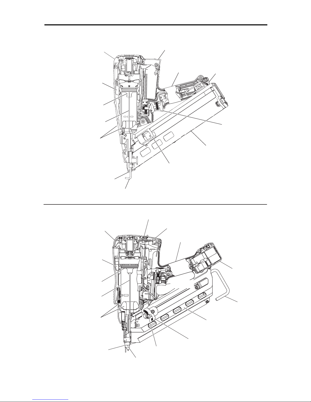
TOOL ILLUSTRATION
-2-
Handle
Top cover
Driver
blade
Chamber
Piston
Magazine
Firing head
(outlet)
Contact Arm
Pusher
Battery
Trigger
Actuator
Exhaust
Outlet
Area
FinishTools:
Chamber
Top cover
Driver
blade
Piston
Magazine
Firing head (outlet)
Handle
Latch
Cell cover
Trigger
Contact Arm
Hook
Pusher knob
Pusher
Battery
FramingTools:
Exhaust
Outlet
Area
-3-
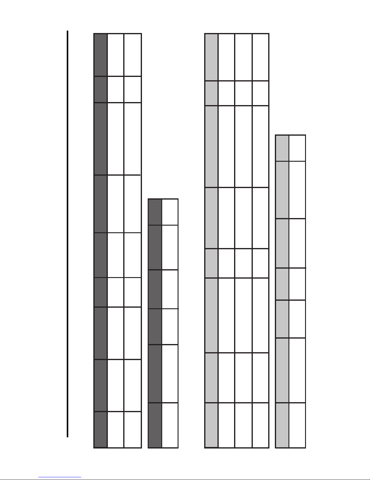
TOOL & CHARGER SPECIFICATIONS
FRAMING FUEL
SKU: 9B12061R
28° Wire Weld
SKU: SXXD-FH
66
Nails
2” - 3-1/2”
50
-
88mm
.113” - .131”
MAGAZINE
CAPACITY
FASTENER
LENGTH
BOSTITCH
FUEL CELL
FASTENERS
FASTENER
DIAMETER
Framing Tools:
TOOL MODEL
Finish Tools:
TOOLSIZE
L
x
W
x
H
WEIGHT BATTERY
33° Paper-Tape
SKU: PT-SXXD
55
Nails
2” - 3-1/2”
50
-
88mm
.113” - .131”
GF33PT
13”
x
4.25”
x
15.25”
330.2 x 107.9 x 387.3mm
7.7lbs
3.493 kg
Ni-Cd 7.2V
GF28WW
13”
x
4.25”
x
15.25”
330.2 x 107.9 x 387.3mm
7.7lbs
3.493 kg
Ni-Cd 7.2V
MAGAZINE
CAPACITY
FASTENER
LENGTH
BOSTITCH
FUEL CELL
FASTENERS
TOOL MODEL
TOOLSIZE
L
x
W
x
H
WEIGHT BATTERY
FINISH FUEL
SKU: 9B12062R
15GA “FN” Nails
SKU: FN15XX
100
Nails
1-1/4” - 2-1/2”
31
-
64mm
GFN1564K
10.75”
x
3.5”
x
10.94”
273 x 88.9 x 277.9mm
4.4lbs
1.99 kg
Li-ion 3.6V
FINISH FUEL
SKU: 9B12062R
16GA Finish Nails
SKU: SB16-XX
100
Nails
1” - 2-1/2”
25
-
64mm
GFN1664K
10.25”
x
3.5”
x
10.94”
260.3 x 88.9 x 277.9mm
4.0lbs
1.81 kg
Li-ion 3.6V
FINISH FUEL
SKU: 9B12062R
18GA Brad Nails
SKU: BT-13XXB
100
Nails
5/8” - 2”
15
-
50mm
GBT1850K
10.63”
x
3.5”
x
11.13”
269.9 x 88.9 x 282.6mm
4.0lbs
1.81 kg
Li-ion 3.6V
DC 12V
60
Min
DC 3.6V
CHARGING
TIME
CHARGING
VOLTAGE
CAR POWER
SOURCE
CHARGING
CURRENT
CHARGER MODEL
CHARGER
WEIGHT
9B12071R
0.4lbs
0.2 kg
DC 1.5A
AC120V 60Hz
Single Phase
60
Min
DC 7.2V
CHARGING
TIME
CHARGING
VOLTAGE
INPUT POWER
SOURCE
CHARGING
CURRENT
CHARGER MODEL
9B12073R
2.4lbs
1.1 kg
DC 1.6A
FRAMING FUEL
SKU: 9B12061R
CHARGER
WEIGHT
AC120V 60Hz
Single Phase
INPUT POWER
SOURCE

INTRODUCTION
B
ostitch Cordless Gas Nailers are precision-built tools, that will deliver efficient, dependable service when used
correctly and with care. As with any fine power tool, for best performance the manufacturer’s instructions must
b
e followed. Please study this manual before operating the tool and understand the safety warnings and
cautions.The instructions on installation, operation and maintenance should be read carefully, and the manuals
k
ept for reference. NOTE: Additional safety measures may be required because of your particular application
of the tool. Contact your Bostitch representative or distributor with any questions concerning the tool and its
use (US: 1-800-556-6696; Canada: 800-567-7705; or www.Bostitch.com). Stanley Fastening Systems, L.P., East
G
reenwich, Rhode Island 02818.
INDEX
Tool Illustration . . . . . . . . . . . . . . . . . . . . . . . . . . . . . . . . . . . . . . . . . . . . . . . . 2
T
ool and Charger Specifications . . . . . . . . . . . . . . . . . . . . . . . . . . . . . . . . . . . 3
Introduction / Warranty . . . . . . . . . . . . . . . . . . . . . . . . . . . . . . . . . . . . . . . . . . 4
S
afety Warnings & Instructions. . . . . . . . . . . . . . . . . . . . . . . . . . . . . . . . . . . 5-6
Battery and Charger Safety Instructions . . . . . . . . . . . . . . . . . . . . . . . . . . . 6-8
Using & Loading Battery . . . . . . . . . . . . . . . . . . . . . . . . . . . . . . . . . . . . . . . . . 8
Preparing the Fuel Cell . . . . . . . . . . . . . . . . . . . . . . . . . . . . . . . . . . . . . . . . . . 9
Installing the Fuel Cell . . . . . . . . . . . . . . . . . . . . . . . . . . . . . . . . . . . . . . . . . 10
Tool Operation Safety. . . . . . . . . . . . . . . . . . . . . . . . . . . . . . . . . . . . . . . . . . . 11
Tool Safety Test . . . . . . . . . . . . . . . . . . . . . . . . . . . . . . . . . . . . . . . . . . . . . . 11
Loading Fasteners . . . . . . . . . . . . . . . . . . . . . . . . . . . . . . . . . . . . . . . . . . . . 12
Tool Operation . . . . . . . . . . . . . . . . . . . . . . . . . . . . . . . . . . . . . . . . . . . . . . . . 13
Jam Clearing Procedure . . . . . . . . . . . . . . . . . . . . . . . . . . . . . . . . . . . . . . . . 13
Dial-A-Depth™ . . . . . . . . . . . . . . . . . . . . . . . . . . . . . . . . . . . . . . . . . . . . . . . . 14
Installing the Belt Hook . . . . . . . . . . . . . . . . . . . . . . . . . . . . . . . . . . . . . . . . . 15
Using Non-Marring Tips. . . . . . . . . . . . . . . . . . . . . . . . . . . . . . . . . . . . . . . . . 15
Maintenance and Troubleshooting Chart . . . . . . . . . . . . . . . . . . . . . . . . . . . 16
Accessories . . . . . . . . . . . . . . . . . . . . . . . . . . . . . . . . . . . . . . . . . . . . . . . . . . 17
NOTE:
Bostitch tools have been engineered to provide excellent customer satisfaction and are designed to achieve
maximum performance when used with precision Bostitch fasteners engineered to the same exacting
standards. Bostitch cannot assume responsibility for product performance if our tools are used with
fasteners or accessories not meeting the specific requirements established for genuine Bostitch nails,
staples and accessories.
LIMITED WARRANTY — U.S. and Canada Only
Stanley Fastening Systems, L.P. (“Bostitch”) warrants to the original retail purchaser that the product purchased is free
from defects in material and workmanship, and agrees to repair or replace, at Bostitch’s option, any defective Bostitch
branded cordless gas stapler or nailer for a period of two (2) years from date of purchase.Warranty is not transferable.
Proof of purchase date required.This warranty covers only damageresulting from defects in material or workmanship;
it does not cover conditions or malfunctions resulting from normal wear, neglect, abuse, accident or repairs attempted
or made by other than our national repair center or authorized warranty service centers. Driver blades, bumpers, orings, pistons and piston rings are considered normally wearing parts. For optimal performance of your Bostitch tool
always use genuine Bostitch fasteners and replacement parts.
THIS WARRANTY IS IN LIEU OF ALL OTHER WARRANTIES, EXPRESS OR IMPLIED, INCLUDING BUT NOT
LIMITEDTOTHEIMPLIED WARRANTIES OF MERCHANTABILITY OR FITNESS FOR A PARTICULARPURPOSE.
BOSTITCH SHALL NOT BE LIABLE FOR ANY INCIDENTAL OR CONSEQUENTIAL DAMAGES.
Some states and countries do not allow limitations on how long an implied warranty lasts, or the exclusion or limitation
of incidental or consequential damages, so the above limitations or exclusions may not apply to you. This warranty
gives you specificlegalrights, and youmay also have otherrights which vary fromstateto state and country to country.
To obtain warranty service in the U.S. return the product, together with proof of purchase, to the U.S. Bostitch National
or Regional Independent Authorized Warranty Service Center. In the U.S. you may call us at 1-800-556-6696 or visit
www.BOSTITCH.com for the location most convenient for you. In Canada please call us at 800-567-7705 or visit
www.BOSTITCH.com
®
™
-4-

-5-
SAFETY INSTRUCTIONS
EYE PROTECTION which conforms to ANSI specifications and provides protection against
f
lying particles both from the FRONT and SIDE should ALWAYS be worn by the operator and
others in the work area when connecting to air supply, loading, operating or servicing this
t
ool. Eye protection is required to guard against flying fasteners and debris, which could
c
ause severe eye injury.
T
he employer and/or user must ensure that proper eye protection is worn. Eye protection
equipment must conform to the requirements of the American National Standards Institute,
ANSI Z87.1 and provide both frontal and side protection. NOTE: Non-side shielded
spectacles and face shields alone do not provide adequate protection.
C
AUTION:
A
dditional Safety Protection will be required in some environments. For
example, the working area may include exposure to noise level which can lead to hearing
d
amage. The employer and user must ensure that any necessary hearing protection is
p
rovided and used by the operator and others in the work area. Some environments will
require the use of head protection equipment. When required, the employer and user must
e
nsure that head protection conforming to ANSI Z89.1 is used.
TOOL AND FUEL WARNINGS
This Nailer produces hot exhaust gases that may ignite flammable materials and produces
sparks during operation.
DO NOT TOUCH THE EXHAUST OUTLET or areas surrounding the exhaust outet during or
after operating the tool. These areas will become HOT creating a BURN HAZARD (see tool
illustration, pg 2).
The contact arm and nose will become hot after prolonged or rapid use. DO NOT TOUCH
with BARE HANDS, allow to cool or use gloves when adjusting a tool that is hot.
EXPLOSION AND FIRE HAZARD. The fuel cell contains highly flammable contents under
pressure. Even empty fuel cells still contain flammable contents, including a pressurized
container and propellant (gas). Failure to follow instructions may result in explosion or fire.
Keep the nailer, fuel cells and battery away from sunlight and from temperature exceeding
120°F (50°C). Fuel cell and/or battery may burst, releasing flammable gas. Do not pierce or
burn the container, even after use. Do not incinerate, refill, reclaim or recycle the fuel cell.
Do not spray into a fire or any incandescent material. Keep away from ignition sources – No
smoking. Keep out of the reach of children.
USE OUTSIDE OR WELL–VENTILATED AREAS.This Nailer exhausts carbon monoxide which
is a danger to your health when inhaled. This Nailer should not be used in enclosed or
poorly ventilated areas. Do not inhale exhaust.
OPERATE WITHIN PROPER TEMPERATURE RANGE. The operating environment for this
device is between 32°F (0°C) and 104°F (40°C) so ensure use within this temperature range.
The device may fail to operate below 32°F (0°C) or above 104°F (40°C).
ALWAYS STORE THE NAILER PROPERLY WITH FUEL CELL AND BATTERY REMOVED. When
not in use, the Nailer, fuel cell and battery should be stored in tool case and in a dry place.
Store indoors at temperature below 120°F (50°C).
ALWAYSTAKE FUEL CELL AND BATTERY OUT OF NAILER WHEN: 1) Doing maintenance and
inspection; 2) clearing a jam; 3) it is not in use; 4) leaving work area; 5) moving it to another
location; and 6) handing it to another person. Never attempt to clear a jam or repair the
Nailer unless you have taken fuel cell and battery out of the Nailer and removed all
remaining fasteners from the Nailer.
LOADING TOOL
When loading tool: 1.) Never place a hand or any part of body in fastener discharge area of
tool; 2.) Never point tool at anyone; 3.) Do not pull the trigger or depress the trip as
accidental actuation may occur, possibly causing injury.
MAINTAINING THE TOOL
When working on gas tools note the warnings in this manual and use extra care when
evaluating problem tools.
EMPLOYER/OWNER RESPONSIBILITIES
It is the employer/owner’s responsibility to ensure this manual is available and understood
by anyone using or maintaining these tools. The employer/owner must ensure all safety
warnings are followed and safety equipment, such as protective eye wear is properly used
by operators and all others in the work area. It is also the responsibility of the
employer/owner to keep tools in safe working order.
SAVE THESE INSTRUCTIONS AND MAKE THEM AVAILABLE TO OTHER USERS
AND OWNERS OF THIS TOOL!
-6-
TOOL SAFETY WARNINGS
Always handle the tool with care: 1.) Never engage in horseplay; 2.) Never pull the trigger
unless nose is directed toward the work; 3.) Keep others a safe distance from the tool while
tool is in operation as accidental actuation may occur, possibly causing injury.
The operator must not hold or carry tool with the trigger pulled as serious injury could
result if the trip accidentally contacted someone or something, causing the tool to cycle.
Keep hands and body away from the discharge area of the tool.
C
heck operation of the contact arm mechanism frequently. Do not use the tool if the arm
is not working correctly as accidental driving of a fastener may result. Do not interfere with
the proper operation of the contact arm mechanism.
Do not drive fasteners on top of other fasteners or with the tool at an overly steep angle as
t
his may cause deflection of fasteners which could cause injury.
Do not drive fasteners close to the edge of the work piece as the wood may split, allowing
the fastener to be deflected possibly causing injury.
T
his nailer produces SPARKS during operation. NEVER use the nailer near flammable
substances, gases or vapors including lacquer, paint, benzine, thinner, gasoline, adhesives,
mastics, glues or any other material that is -- or the vapors, fumes or by-products of which are -
- flammable, combustible or explosive. Using the nailer in any such environment could cause an
EXPLOSION resulting in personal injury or death to user and bystanders.
IMPORTANT SAFETY INSTRUCTIONS FOR USE OF THE
BATTERY AND CHARGER
You must charge the battery before using the nailer.
Before using the Bostitch battery charger 9B12073R or 9B12071R, be sure to read and
understand all instructions, warnings and cautionary statements on it, the battery and in this
manual.
USE ONLY BOSTITCH BATTERIES 9B12072R AND 9B12070R. OTHER TYPES OF BATTERIES
MAY BURST AND RESULT IN RISK OF FIRE, ELECTRICAL SHOCK OR PERSONAL INJURY!
Follow these instructions to avoid the risk of injury.
Improper use of the battery or battery charger can lead to serious injury or DEATH.
DISPOSAL OF THE EXHAUSTED BATTERY: Do not throw battery in the trash. The battery
will explode if incinerated.The battery is rechargeable and recyclable. Call 1-800-822-8837
for recycling instructions for batteries or check with your local solid waste officials for
proper disposal instructions. Depending on local law, it may be illegal to dispose of battery
in any other manner.
IMPORTANT: To ensure product SAFETY and RELIABILITY, repairs, maintenance and adjustments should be
performed by a qualified technician, who always uses identical replacement parts.
1. NEVER disassemble the battery.
2. NEVER incinerate the battery, even if it is
damaged or is completely worn out. The
battery can explode in a fire.
3. NEVER short-circuit the battery.
4. NEVER insert any objects into the battery
charger’s air vents. Electric shock or
damage to the battery charger may
result.
5. NEVER charge outdoors. Keep the battery away
from direct sunlight and use only where
there is low humidity and good
ventilation.
6. NEVER charge when the temperature is below
50°F (10°C) or above 104°F (40°C).
7. NEVER connect two battery chargers together.
8. NEVER
insertforeign objects into the holefor the
battery or the battery charger.
9. NEVER
use a booster transformer when
charging.
10. NEVER
use a gas engine generator or DC power
to charge.
11. NEVER
store the battery or battery charger in
places where thetemperature may reach
or exceed 104°F (40°C).
12. ALWAYS operate charger on standard household
electrical power (120 volts). Using the
charger on any other voltage may
overheat and damage the charger.
13. ALWAYS wait at least 15 minutes between charges
to avoid overheating the charger.
14. ALWAYS disconnect the power cord from its
receptacle when the charger isnot in use.
BATTERY CHARGER MAINTENANCE
Disconnect charger from AC outlet before cleaning. Dirt and grease may be removed from
the exterior of the charger by using a cloth or a soft non-metallic brush. Do not use water
or any cleaning solutions. Do not freeze or immerse charger in water or any other liquid.
-7-
1. Use the battery charger correctly.
Do not use the battery charger other than with a DC
12V in-car power source. The battery charger is solely
for use on nagative-grounded vehicles. Make sure that
the negative pole of the car battery is connected to the
car body.
2. Keep your attention focused on driving the car.
If you use the battery charger while driving, fasten the
battery charger in place so that it does not move
inadvertently and distract your attention from driving.
Do not place the battery charger or battery under the
driver’s seat, irrespective of whether it is charging or
not, as it may get under the brake pedal or the cable
may get wrapped around the driver’s feet and cause an
accident.
3. Do not manipulate the battery charger or battery while
driving as this may cause an accident.
4. Do not leave the battery charger or battery within
reach of children as this may result in an accident.
5. Be use to use the cable provided.
Using a different cable could result in a fire or accident
due to overheating.
6. Do not place the battery charger on a blanket-type car
seat cover or car mat during charging as this may
result in a fire or accident due to overheating.
7. Do no expose the battery charger to direct sunlight
during charging as this may result in a fire.
8. Do not leave the vehicle unattended during charging.
PRECAUTIONS WHEN USING THE BATTERY CHARGER
WITH A DC 12V IN-CAR POWER SOURCE
IMPORTANT SAFETY INSTRUCTIONS FOR
BATTERY CHARGER
Don’t allow any liquid to get inside charger. Electric shock may result. To facilitate the cooling of the
battery pack after use, avoid placing the charger in a warm environment such as in a metal shed, or an
uninsulated trailer.
Death or serious bodily injury could result from improper or unsafe use of battery chargers. To avoid these
risks, follow these basic safety instructions:
READ ALL INSTRUCTIONS
1. This manual contains important safety and
o
perating instructions for Bostitch battery chargers
9B12071R or 9B12073R.
2. Before using battery charger, read all instructions
and cautionary markings on (1) battery charger,
(2) battery, and (3) product using battery.
3.
To reduce risk of injury, charge only Bostitch
rechargeable batteries 9B12070R or 9B12072R.
Other
types
of batteries may burst causing
personal
injury and damage.
4. Do not expose battery charger to rain or snow.
5. Use of an attachment not recommended or sold
by Bostitch may result in a risk of fire, electical
shock, or personal injury.
6. To reduce riskof damage to electric plug and cord,
only pull by plug when disconnecting battery charger.
7. Make sure cord is located so that it will not be
stepped on, tripped over, or otherwise subjected
to damage or stress.
8. An extension cord should not be used unless
absolutely necessary. Use of improper extension
cord could result in arisk of fire and electric shock.
If extension cord must be used make sure:
a. That blades of extension cord are thesame number,
size, and shape asthose of plug on battery charger;
b. That extension cord is properly wired and in good
electrical condition; and
c. That wire size is large enough forAC ampere rating
of battery charger as specified in Table 1.
* If the input rating of a battery charger is given in
watts rather than in amperes, the corresponding
ampere rating is to be determined by dividing the
wattage rating by the voltage rating–for example:
1,250 watts
125 volts
=
10 amperes
9.
Do notoperate battery charger with a damaged cord
or plug, Replace them immediately.
Do not operate battery charger if it has received a
sharp blow, been dropped, or otherwise damaged
in any way; take it to a qualified serviceman.
D
o not disassemble battery charger; take it to a
qualified serviceman when service or repair is
required. Incorrect reassembly may result in a risk
of electric shock, death or fire.
10. To reduce risk of electric shock, unplug charger
from rece ptacle before attempting any
maintenance or cleaning. Removingthe battery will
not reduce this risk.
11.
This battery charger might be attached to
Bostitch
battery operated tools as a standard accessory. In
this case, please confirm Instruction Manual of the
Bostitch
battery operated tools before using the
battery charger.
Table 1
R
ECOMMENDED MINIMUM AWG SIZE FOR
EXTENSION CORDS FOR BATTERY CHARGERS
AC Input Rating Amperes* AWG Size of Cord
Equal to or but less Length of Cord, Feet (Meter)
greater than than 25 (7.5) 50 (15) 100 (30) 150 (45)
0 2 18 18 18 16
2 3 18 18 16 14
3 4 18 18 16 14
12.
Unplug charger when not in use. Remove battery
packs from unplugged chargers.
13.
IMPORTANT: This product is not user serviceable.
There are no user serviceable parts inside the
charger. Servicing at the closest Authorized
Service Center is required to avoid damage to
static sensitive internal components.
-8-
TOOL BATTERY
NEVER charge the batteries at a voltage higher than indicated on the nameplate. Charging at
a
higher voltage creates fire hazard.
Do not use charger if electrical cord is damaged.
Do not place battery charger under driver’s seat (Fig. 2). When charging battery in vehicle,
s
ecure charger using strap supplied. (Fig. 3)
Do not leave battery charger or battery in car.
The battery used in this device may present a risk of fire or chemical burn if mistreated. Do
not recharge, disassemble, heat above 104°F (40°C), or incinerate.
Replace the battery ONLY with the same type of Bostitch battery designed for your tool, use
of another battery may present a risk of fire or explosion.
NEVER charge a battery or leave the battery in direct sun light, it may burst causing injury or
a fire.
NEVER disassemble the battery.
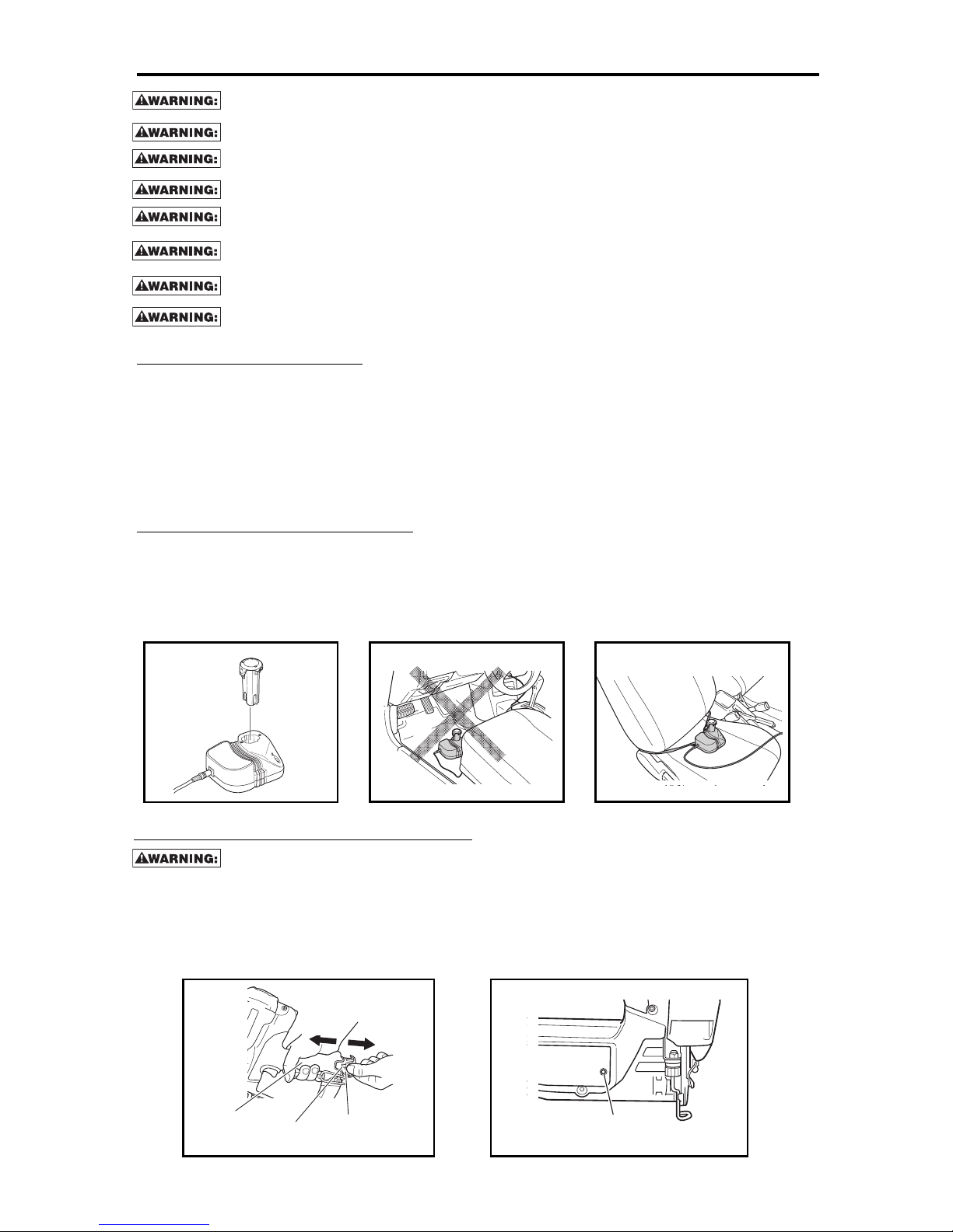
Using the Battery Charger
1. Insert power cord end into charger (for model 9B12071R charger).
2. Insert plug into electrical source.
3. Insert battery into charger (Fig. 1). Indicator light will come on.
4. Indicator light will turn off when battery is fully charged. If light does not go out after 4 hours, unplug
charger and contact Bostitch, as service may be necessary.
5. Remove battery from charger (Fig. 1).
6. Unplug charger when not in use.
NOTE: acceptable temperature range for charging batteries: 32°-104°F (0°-40°C).
Optimizing Battery Performance
1. Recharge batteries before they become completely exhausted. Overdrawing battery power will shorten life.
2. Allow batteries to cool after use before charging. Battery performance will deteriorate if a hot battery is
charged immediately after use.
3. New batteries (or batteries not used for an extended period) may need to be charged 2-3 times before
peak performance is reached.
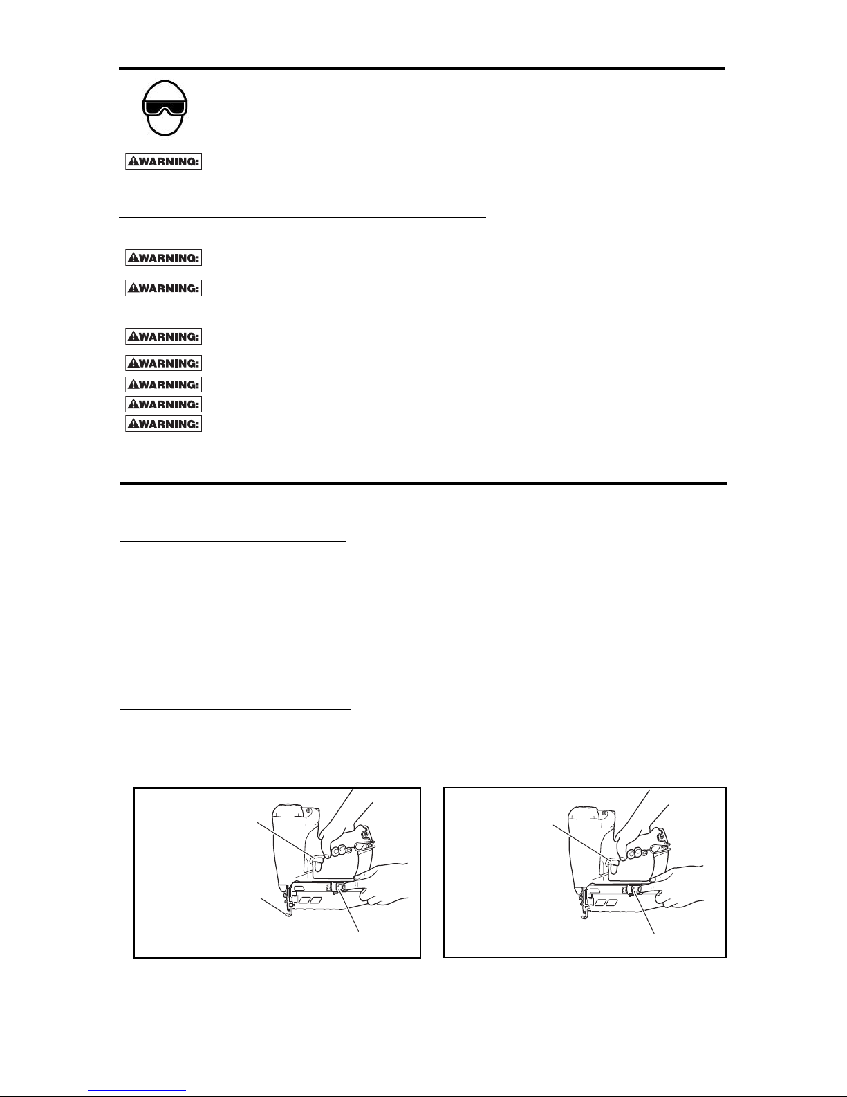
LOADING BATTERY INTO THE TOOL
1. Once battery is charged, insert battery into back of tool handle. (Fig. 4)
2. Flashing GREEN light indicates “Ready to drive fasteners”. (Fig. 5)
3. Flashing RED light indicates “Battery is empty - Recharge battery”
4. If no light comes on when battery is inserted, either battery is depleted or tool needs service.
5. To remove battery from tool, press battery release button and pull battery out of tool.
Handle
Battery
release button
Battery
Pull out
Insert
Battery indicator
light
12 3
45
Never use the tool unless the indicator light is GREEN.
-9-
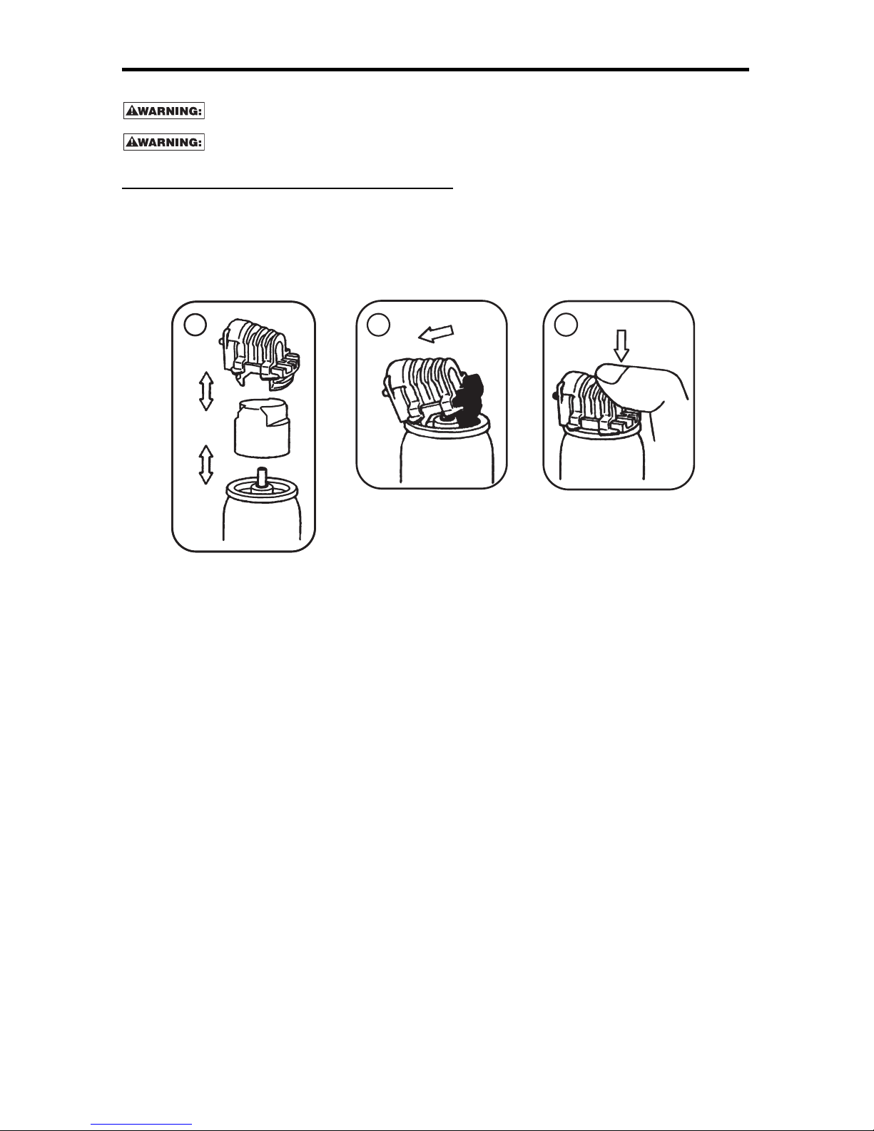
PREPARING THE FUEL CELL
READ SECTION TITLED “INSTALLING FUEL CELL” SAFETY INSTRUCTIONS ON PAGE 10.
If the gas leaks from the metering valve or the gas cartridge after attaching the metering
v
alve, replace with new metering valve.
Do not attempt to reuse the metering valve. Replace with new metering valve.
To attach the metering valve to a fuel cell:
1. Separate the metering valve and the cap from the gas cartridge.
2. Press forward (stem side) and downward on the front side of the metering valve.
3
. Press downward on the rear of the metering valve until it seals
1
2
3
-10-
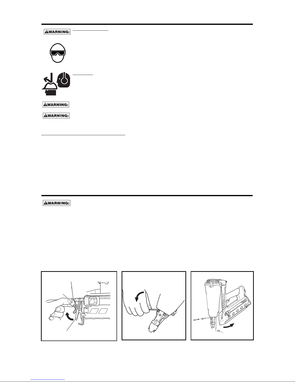
INSTALLING FUEL CELLS
F
UEL CELL CONTENTS EXTREMELY FLAMMABLE. Do not incinerate even when empty.
F
UEL CELL CONTENTS UNDER PRESSURE: Keep away from temperatures over 120˚F (50˚C).
K
eep out of sun. Store at room temperature (68°-80°F / 20°-27°C).
K
EEP OUT OFTHE REACH OF CHILDREN.
M
AY FORM FLAMMABLE/EXPLOSIVE VAPOR-AIR MIXTURE: Do not use near flames or
spray on heated surfaces. Keep away from ignition sources. Use only outside or in well
ventilated rooms. Keep container in well ventilated place.
No Smoking when handling fuel cells.
IRRITANT - KEEP AWAY FROM SKIN AND EYES. NOT FOR HUMAN CONSUMPTION.
VAPOR HARMFUL - DO NOT INHALE GAS
D
o not puncture or attempt to open the gas cartridge, it is non-refillable.
1. Install metering valve on fuel cell (see directions on Preparing the Fuel Cell located on page 9 and printed
directly on fuel cell).
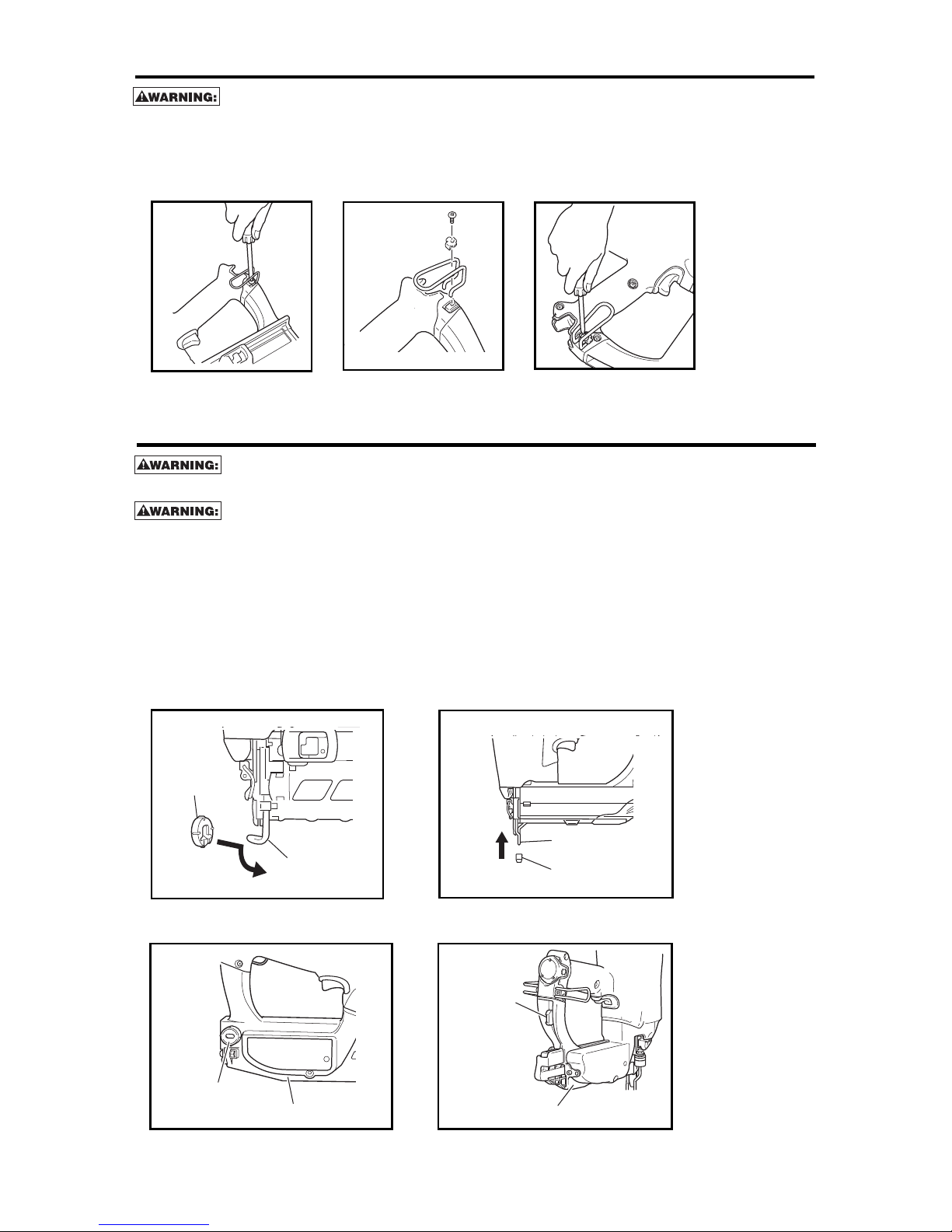
2. Unlatch the fuel cell cover (actuator) at top of tool. (Fig. 1A for Finish Tools, Fig. 1B for Framing Tools)
3. Insert fuel cell into the nailer (Fig. 2). Be sure to use proper fuel cell for your model, see chart on page 7.
4. Insert stem of fuel cell into adapter (Fig. 3 & 4).
5. If adapter becomes loose, reinsert into hole in tool body (Fig. 5).
6. Close fuel cell cover (actuator). (Fig. 6A for Finish Tools, Fig. 6B for Framing Tools)
Fuel cell
Adapter
Stem
Fuel cell
Stem
Fuel cell
Adapter
Adapter
Insert into the hole
1. Swing back
2. Push down
2. Pull out
1. Push up
1A
Latch
Cell cover
1B
3
5 6A
4
2
Cell cover
6B
-11-
TOOL OPERATION SAFETY
EYE PROTECTION which conforms to ANSI specifications and provides protection against
flying particles both from the FRONT and SIDE should ALWAYS be worn by the operator and
others in the work area when connecting to air supply, loading, operating or servicing this
tool. Eye protection is required to guard against flying fasteners and debris, which could
cause severe eye injury.
The employer and/or user must ensure that proper eye protection is worn. Eye protection
equipment must conform to the requirements of the American National Standards Institute,
A
NSI Z87.1 and provide both frontal and side protection. NOTE: Non-side shielded spectacles
and face shields alone do not provide adequate protection.
BEFORE HANDLING OR OPERATING THIS TOOL:
READ AND UNDERSTAND ALL THE WARNINGS CONTAINED IN THIS MANUAL.
Always keep your finger off the trigger, unless contact arm is against the work surface and
y
ou intend to drive a fastener.
This tool has a fan which will turn on whenever the contact arm is depressed. The fan will
continue to run for 10 seconds after the fastener is driven.
COLD WEATHER CARE:
Do not store the nailer, fuel cell or battery in a cold weather environment. Keep the nailer,
fuel cell and battery stored at room temperature (68°-80°F / 20°-27°C).
If the nailer, fuel cell or battery are below 32°F (0°C) nailer may not drive completely.
No not use the nailer in rain or where excessive moisture is present.
Do not expose to an open flame or sparks.
This nailer is not recommended for use in altitudes above 5,000 feet (1,500 meters).
Depress contact arm
Pusher
Do not pull trigger
TOOL SAFETY TEST
Once battery and fuel cell is installed in tool, complete the following 3 tests to ensure tool safety features are
operating properly. Complete tests whenever fuel cell or battery is replaced, or at least once per day of use.
TEST1 (without nails loaded):
1. Press contact arm against work surface while pulling back pusher. DO NOT PULL TRIGGER (Fig. 1).
Tool should not cycle. If tool cycles contact Bostitch, as service is necessary. DO NOT USE TOOL.
TEST 2 (without nails loaded):
1. Lift tool so contact arm is not touching work surface. (Fig. 2)
2. Pull back pusher.
3. Pointing nailer down, away from face and body, pull trigger and hold for 5 seconds. Tool should not
cycle. If tool cycles contact Bostitch, as service is necessary. DO NOT USE TOOL.
TEST 3 (without nails loaded):
1. Press contact arm against work surface while pulling back pusher.
2. Pull trigger.
3. Tool should cycle. If no abnormal operation is observed tool is ready to load nails.
Pusher
Pull trigger
1
2
-12-
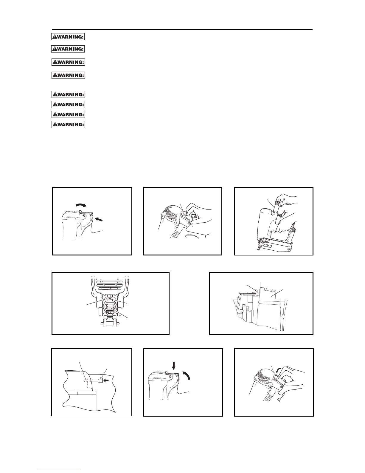
LOADING FASTENERS INTO GBT1850K
1. Depress magazine release button and pull back magazine.
2. Open magazine fully and turn tool sideways with discharge area pointed away from yourself and others.
3. Load brads in channel, point side down, touching bottom.
4. Push magazine forward until latch is engaged.
Magazine Release
Button
Magazine
Pull out
Press
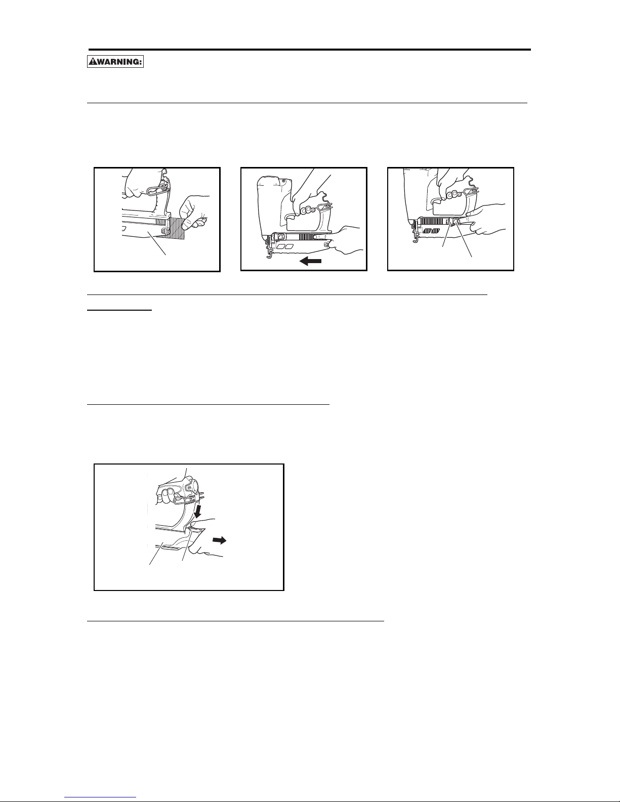
LOADING FASTENERS
N
ever touch trigger or depress contact arm when loading nails. Keep nailer pointing
downward
LOADING FASTENERS INTO GF28WW, GF33PT, GFN1564K & GFN1664K
1. Insert stick of nails into back of magazine.
2. Slide nails forward to front of magazine.
3
. Press button on pusher and slide pusher backward, behind nails.
4. Release button to engage pusher behind nails.
Magazine
Pusher
Button
UNLOADING FASTENERS FROM GF28WW, GF33PT, GFN1564K &
GFN1664K
1. Pull the pusher backwards.
2. Slide unlocked pusher forward, past nails.
3. Remove stick of nails by sliding out the back of the magazine.
UNLOADING FASTENERS FROM THE GBT1850K
1. Depress magazine release button and pull back magazine.
2. Open magazine fully and remove brads from channel.
3. Push magazine forward until latch is engaged.
-13-
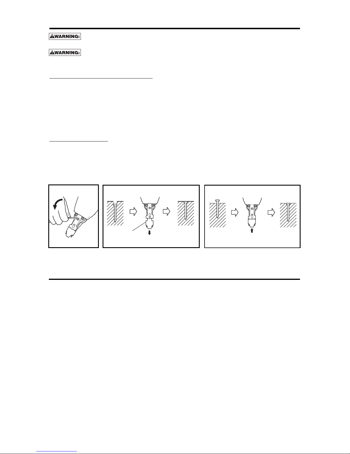
JAM CLEARING PROCEDURE
Disconnect fuel cell and battery before making adjustments or before attempting any part
assembly or disassembly.
On occasion nails can jam in the nose of a cordless tool. This can be caused by striking a metal plate in the
wall, drywall screw, or some other hard object. If this occurs follow these steps.
1. Remove the fuel cell, battery and fasteners from the tool.
2. Open the area of jam. (Fig. 1A for Finish Tools, Fig. 1B & 1C for Framing Tools)
3. Remove the jammed fastener. In certain circumstances, pliers or small screwdriver may be required to
remove the fastener.
4. Close tool.
Guide Plate
Lock lever
3
1A Finish Tools
1B Framing Tools
Convex side
1C Framing Tools
TOOL OPERATION
EYE PROTECTION which conforms to ANSI specifications and provides protection against
flying particles both from the FRONT and SIDE should ALWAYS be worn by the operator and
others in the work area when connecting to air supply, loading, operating or servicing this
tool. Eye protection is required to guard against flying fasteners and debris, which could
c
ause severe eye injury.
The employer and/or user must ensure that proper eye protection is worn. Eye protection
equipment must conform to the requirements of the American National Standards Institute,
A
NSI Z87.1 and provide both frontal and side protection. NOTE: Non-side shielded
spectacles and face shields alone do not provide adequate protection.
C
AUTION:
A
dditional Safety Protection will be required in some environments. For example,
the working area may include exposure to noise level which can lead to hearing damage.
The employer and user must ensure that any necessary hearing protection is provided and
u
sed by the operator and others in the work area. Some environments will require the use
of head protection equipment. When required, the employer and user must ensure that head
p
rotection conforming to ANSI Z89.1 is used.
A
lways keep your finger off the trigger, unless contact arm is against the work surface and
you intend to drive a fastener.
This tool has a fan which will turn on whenever the contact arm is depressed. The fan will
continue to run for 10 seconds after the fastener is driven.
SEQUENTIAL TRIP OPERATION:
This tool is equipped with a sequential trigger (GRAY). The contact trip operates in conjunction with the trigger
to drive a fastener. To operate a sequential trip tool:
1. Place tool on the work surface WITHOUT PULLING THE TRIGGER.
2. Completely compress the contact trip.
3. Pull the trigger to drive a fastener.
If the contact trip is allowed to leave the work surface, the sequence described above must be repeated to drive
another fastener.
-14-
DIAL-A-DEPTH™ FASTENER CONTROL ADJUSTMENT
Always disconnect fuel and battery before making adjustments or before attempting any
part assembly or disassembly.
The contact arm and nose will become hot after prolonged or rapid use. DO NOT TOUCH
with BARE HANDS, allow to cool or use gloves when adjusting a tool that is hot.
For GFN1564K, GFN1664K and GBT1850K
The DIAL-A-DEPTH™ Fastener control adjustment feature provides close control of the fastener drive depth:
f
rom flush with the work surface to shallow or deep countersink.
1
. Remove the fuel cell and battery from tool.
2. If nails are driving too deep, turn the adjustment knob to the shallow side.
3. If fasteners are not driven deep enough, turn to the deep side.
4. Adjustments are in half-turn increments.
5. Reconnect fuel cell and battery to test.
For GF28WW & GF33PT
1. Remove the fuel cell and battery from tool.
2. Loosen bolt on nose with provided hex wrench.
3. If nails are driving too deep, adjust the contact arm down.
4. If fasteners are not driven deep enough, adjust contact arm up.
5. Reconnect fuel cell and battery to test.
IN ADDITION TO THE OTHER WARNINGS CONTAINED IN THIS
MANUAL OBSERVE THE FOLLOWING FOR SAFE OPERATION
• Use the BOSTITCH cordless tool only for the purpose for which it was designed.
• Never use this tool in a manner that could cause a fastener to be directed toward the user
or others in the work area.
• Do not use the tool as a hammer.
• Always carry the tool by the handle.
• Do not alter or modify this tool from the original design or function without approval from
BOSTITCH, INC.
• Always be aware that misuse and improper handling of this tool can cause injury to
yourself and others.
• Never clamp or tape the trigger or contact arm in an actuated position.
• Never leave a tool unattended with the battery or fuel cell installed.
• Do not operate this tool if it does not contain a legible WARNING LABEL.
• Do not continue to use a tool that leaks fuel or does not function properly. Notify your nearest
Bostitch representative if your tool continues to experience functional problems.
Contact Arm
1
2
3
-15-
INSTALLING THE BELT HOOK
A
lways disconnect fuel and battery before making adjustments or before attempting any
p
art assembly or disassembly.
Hook can be used on either side of the tool. To remove, replace or switch belt hook side, see Fig. 1 & 3.
1
. Remove the fuel cell and battery from the tool.
2. Hook is held in by a screw and a hook plate. (Fig. 2)
1
3
2
USING THE NON-MARRING FINISHTIPS
Always disconnect fuel and battery before making adjustments or before attempting any
part assembly or disassembly.
The contact arm and nose will become hot after prolonged or rapid use. DO NOT TOUCH
with BARE HANDS, allow to cool or use gloves when adjusting a tool that is hot.
The no-mar tips are used to prevent scratches to the work surface. Use the following steps to install the nomar tip to the contact arm:
1. Remove the fuel cell and battery from the tool.
2. Remove no-mar tip from storage compartment located on the reverse side of the magazine. (Fig. 6 &7)
3. Install no-mar tip on contact arm, note markings to indicate the exit location of the nail to help with proper
positioning. (Fig. 4 & 5)
4. When not in use, no-mar tip can be returned to storage location.
Contact Arm
No-Mar Tip
No-Mar Tip
Magazine
Magazine
No-Mar
Tip
No-Mar Tip
Contact Arm
2
4
7
6
5

-16-
Maintenance chart
ACTION WHY HOW
Clean magazine and pusher Prevent a jam. Blow clean daily.
mechanism.
Keep contact arm working properly. Promote operator safety and Blow clean daily.
efficient Nailer operation.
Operator troubleshooting
P
ROBLEM
Nailer operates, but no nail is driven.
Skipping nails.
Intermittent feed.
Nails jam.
Driven nail is bent.
The operation of the contact arm not
smooth.
Fan is working, light indicator shows
GREEN yet it doesn’t drive a nail or
operation unstable.
Fan does not operate when push lever
is pressed.
Unable to charge battery.
C
HECK METHOD CORRECTION
C
heck for a jam. Clear a jam.
Check function of pusher. Clean and lubricate.
Ribbon spring weakened or damaged? Replace ribbon spring.
C
heck for proper nails. Use only recommended nails.
Check if the driver blade piston is down Push the driver blade with a slottedor not. head screwdriver, and put back the
piston to the highest position.
Check for proper nails. Use only recommended nails.
Check function of pusher. Clean and lubricate.
Ribbon spring weakened or damaged? Replace ribbon spring.
Pusher worn or damaged? Replace pusher.
Check for returning of piston. Pull the trigger all the way.
Too low temperature, warm up
fuel cell under 120°F (50°C).
Check for moving of piston smoothly. Contact Bostitch for replacement.
Replace piston ring.
Replace piston.
Replace cylinder piston ring.
Check for proper nails. Use only recommended nails.
Driver blade worn? Contact Bostitch for replacement.
Pusher worn or damaged? Replace pusher.
Contact arm bent? Contact Bostitch for replacement.
Check contact arm’s moving track, debris?
Contact Bostitch for replacement.
Check for returning of piston. Push the contact arm all the way.
Too low temperature, warm up
fuel cell under 120°F (50°C).
Check fuel cell, insufficient? Exchange it with a new fuel cell.
Check spark plug wire, worn out? Contact Bostitch for replacement.
Check spark plug, grease or debris? Contact Bostitch for replacement.
Check filter, clogged? Clean as instructed on the
maintenance sheet.
Magazine empty. Load more nails in the magazine.
Note the color of the light indicator. If red: charge the battery.
If green: Contact Bostitch for
replacement.
Check the electrical cord.
 Loading...