

Page 1
GF28WW, GF33PT, GCN40T
GAS TOOL SAFETY & OPERATING INSTRUCTIONS (ORIGINAL INSTRUCTIONS)
OUTIL A GAZ, MODE D'EMPLOI & CONSIGNES DE SECURITE (TRADUCTION DE L’ORIGINAL)
SICHERHEITS- UND BEDIENUNGSANLEITUNG FÜR GASWERKZEUGE (ÜBERSETZUNG DES ORIGINALS)
VEILIGHEIDSINSTRUCTIES & HANDLEIDING GASGEREEDSCHAP (VERTALING VAN ORIGINEEL)
SIKKERHED- & BRUGSVEJLEDNING FOR GAS VÆRKTØJ (OVERSÆTTELSE AF ORIGINAL)
KAASUTYÖKALUN TURVALLISUUS- JA KÄYTTÖOHJEET (KÄÄNNÖS ALKUPERÄISESTÄ)
ΟΔΗΓΙΕΣ ΑΣΦΑΛΕΙΑΣ & ΧΡΗΣΗΣ ΕΡΓΑΛΕΙΟΥ ΑΕΡΙΟΥ (ΜΕΤΑΦΡΑΣΗ ΑΠΟ ΤΟ ΠΡΩΤΟΤΥΠΟ)
ISTRUZIONI DI SICUREZZA E D’USO DEGLI UTENSILI A GAS (TRADUZIONE DELL’ORIGINALE)
SIKKERHETSINSTRUKSJONER OG BRUKSANVISNING FOR GASSVERKTØY (OVERSETTELSE FRA ORIGINAL)
SEGURANÇA DA FERRAMENTA A GÁS E INSTRUÇÕES DE OPERAÇÃO (TRADUÇÃO DO ORIGINAL)
INSTRUCCIONES DE SEGURIDAD Y EMPLEO PARA HERRAMIENTAS A GAS (TRADUCCIÓN DEL ORIGINAL)
SÄKERHETS- OCH BRUKSANVISNING FÖR GASDRIVNA VERKTYG (ÖVERSÄTTNING AV ORIGINAL)
INSTRUKCJA OBSŁUGI I BEZPIECZEŃSTWA NARZĘDZIA GAZOWEGO (TŁUMACZENIE Z WERSJI ORYGINALNEJ)
BEZPEČNOSTNÍ A PROVOZNÍ POKYNY PRO PLYNOVÝ NÁSTROJ (PŘEKLAD ORIGINÁLU)
BEZPEČNOSTNÉ POKYNY A NÁVOD NA POUŽITIE PLYNOVÉHO NÁRADIA (PREKLAD ORIGINÁLU)
GÁZPATRONOS SZERSZÁM – BIZTONSÁGI ÉS ÜZEMELTETÉSI UTASÍTÁSOK (EREDETI SZÖVEG FORDÍTÁSA)
INSTRUCŢIUNI DE OPERARE ŞI SIGURANŢĂ PENTRU SCULE ELECTRICE (TRADUCEREA INSTRUCŢIUNILOR ORIGINALE)
GB
FR
DE
NL
DK
FI
GR
IT
NO
PT
ES
SE
PL
CZ
SK
HU
www.bostitch.eu
RO
Page 2

GF28WW
A 347 B 353 C 110 D 3.4 E 99 F 108
G 3.5 H S / WW I (a) 2.8x3.3mm I(b) 50-90mm J 7.5mm K 66
L 0-40ºC M 9B12073R-E/U N AC 230V 50Hz O 60 P 7.2V Q 2.6A
R 1.1 S 0.3 T 9B12072R-EU (1.4Ah) Ni-Cd 7.2v U 80ml
GF33PT
A 347 B 353 C 110 D 3.4 E 99 F 108
G 3.5 H PT I (a) 2.8-3.3mm I(b) 50-90mm J 6.8-7.7mm K 55
L 0-40ºC M 9B12073R-E/U N AC 230V 50Hz O 60 P 7.2V Q 2.6A
R 1.1 S 0.3 T 9B12072R-EU (1.4Ah) Ni-Cd 7.2v U 80ml
GCN40T
A 420 B 353 C 110 D 3.4 E 99 F 108
G 3.5 H CN I (a) 2.6mm I(b) 15-40mm J 6.3mm K 40
L 0-40ºC M 9B12073R-E/U N AC 230V 50Hz O 60 P 7.2V Q 2.6A
R 1.1 S 0.3 T 9B12072R-EU (1.4Ah) Ni-Cd 7.2v U 80ml
J
I(b)
I(a)
GF33PT
J
I(b)
I(a)
GCN40T
J
I(b)
I(a)
GF28WW
TOOL TECHNICAL DATA
DONNÉES TECNIQUES
TECHNISCHE GERÄTEDATEN
TECHNISCHE SPECIFICATIE
TEKNISKE DATA
TEKNISET TIEDOT
Τεχνικ στοιχεα
DATI TECNICI
GB
FR
DE
NL
DK
FI
GR
IT
NO
PT
ES
SE
PL
CZ
SK
HU
TEKNISKE DATA
ESPECIFICAÇÕES TÉCNICAS
ESPECIFICACIONES TÉCNICAS
TEKNISK DATA
DANE TECHNICZNE NARZ¢DZI
TECHNICKÁ DATA NÁSTROJE
TECHNICKÉ PARAMETRE
A SZERSZÁM MÙSZAKI ADATAI
Page 3

English
Top cover
Housing
Chamber
Piston
Driver blade
Push lever
Firing head (Outlet)
Nail feeder (B)
Feeder Knob
Magazine
Hook
Battery
Trigger
Handle
Cell Cover
Latch
Charger
Pilot lamp
Fuel cell
Metering valve
Stem
Cap
Latch (Battery)
Indicator light
Adapter
Hexagonal bar wrench
Convex side
Nail Stopper
Nose Cap
Magazine Catch
Français
Couvercle supérieur
Carcasse
Chambre
Piston
Plaque d'enfoncement
Bras de contact
Tête de clouage (Embout)
Distributeur de clous (B)
Bouton du distributeur
Magasin
Crochet
Batterie
Gâchette
Poignée
Couvercle de la cartouche
Dispositif de fermeture
Chargeur
Voyant lumineux
Cartouche de combustible
Valve de niveau
Souche
Capot
Dispositif de fermeture (Batterie)
Voyant lumineux
Adaptateur
Clef hexagonale
Côté convexe
Butée à clous
Capot du nez
Dispositif de fermeture du magasin
Deutsch
Obere Abdeckung
Gehäuse
Kammer
Kolben
Treiber
Kontaktarm
Schießkopf (Auslass)
Nagelzuführung (B)
Riegel der Zuführung
Magazin
Aufhängung
Batterie
Auslöser
Gri
Abdeckung der Brennstozelle
Riegel
Ladegerät
Anzeigeleuchte
Brennstozelle
Dosierventil
Schaft
Kappe
Riegel (Batterie)
Anzeigeleuchte
Adapter
Sechskantschlüssel
Gewölbte Seite
Nagelstopper
Nasenkappe
Magazinverriegelung
Nederlands
Deksel bovenkant
Behuizing
Kamer
Piston
Aandrijfschijf
Contactarm
Kop (uitlaat)
Nagelaanvoer (B)
Knop van de aanvoer
Magazijn
Haak
Accu
Trekker
Handvat
Celdeksel
Hendel
Lader
Lampje van de indicator
Brandstofcel
Doseerklep
Steel
Kap
Hendel (accu)
Lampje van de indicator
Adapter
Hexagonale inbussleutel
Convexzijde
Nagelstopper
Neuskap
Magazijnhaak
1
2
3
4
5
6
7
8
9
10
11
12
13
14
15
16
17
18
19
20
21
22
23
24
25
26
27
28
29
30
Dansk
Topdæksel
Kabinet
Kammer
Stempel
Drivblad
Kontakt arm
Ayringshoved (Udgang)
Søm føder (B)
Fødergreb
Magasin
Krog
Batteri
Aftrækker
Håndtag
Celle dæksel
Holdemekanisme
Oplader
Indikatorlys
Brændselscelle
Doseringsventil
Spindel
Dæksel
Holdemekanisme (Batteri)
Indikatorlys
Adapter
Sekskantet skruenøgle
Konveks side
Søm stopper
Næse dæksel
Magasin lås
Suomi
Päällyskansi
Kotelointi
Kammio
Mäntä
Iskuriterä
Kontaktivarsi
Laukaisupää (ulostulo)
Naulansyöttäjä (B)
Syöttönuppi
Lipas
Koukku
Akku
Liipaisin
Kahva
Kennon kansi
Salpa
Laturi
Merkkivalo
Polttoainekenno
Annosteluventtiili
Tyvi
Korkki
Salpa (Akku)
Merkkivalo
Sovitin
Kuusiokoloavain
Kupera sivu
Naulan pysäytin
Kärkikorkki
Lippaan salpa
Ελληνικά
Πάνω κάλυµµα
Θήκη
Κλίβανοσ
Έµβολο
Κύρια λείδα
Ράουλο διανοµέα
Σηµείο υροδότησησ (διανοµέασ)
Τροφοδότησ καρφιών (Β)
Διακότησ τροφοδότη
Πλαίσιο (θηκών)
Γάντζοσ
Ματαρία
Σκανδάλη
Χειρολαβή
Κάλυµµα κυψέλησ
Μάνδαλοσ
Φορτιστήσ
Φωτεινόσ δείκτησ
Κυψέλη καυσίµου
Δοσιµετρική βαλβίδα
Κάλυκασ
Καάκι
Μάνδαλοσ (Ματαρία)
Φωτεινόσ δείκτησ
Προσαρµοστήσ
Εξαγωνικό κλειδί σύσφιξησ
Κυρτή λευρά
Αναστολέασ καρφιών
Θόλοσ οµφαλού έλικα
Άγκιστρο ασφάλισησ λαισίου (θηκών)
Italiano
Coperchio superiore
Rivestimento
Camera
Pistone
Martelletto
Braccio di contatto
Testina di sparo (foro di uscita)
Alimentatore dei chiodi (B)
Manopola dell’alimentatore
Caricatore
Gancio
Batteria
Grilletto
Impugnatura
Coperchio della cella
Chiusura a scatto
Caricabatteria
Spia luminosa
Pila a combustibile
Valvola di dosaggio
Beccuccio
Cappuccio
Chiusura a scatto (batteria)
Spia luminosa
Adattatore
Chiave esagonale
Lato convesso
Arresto chiodi
Cappuccio per la punta
Fermaglio del caricatore
1
2
3
4
5
6
7
8
9
10
11
12
13
14
15
16
17
18
19
20
21
22
23
24
25
26
27
28
29
30
Page 4

Norsk
Toppdeksel
Hus
Kammer
Stempel
Driverblad
Kontaktarm
Spikerutløp
Spikermater (B)
Materknast
Magasin
Krok
Batteri
Avtrekker
Håndtak
Beholderdeksel
Lås
Lader
Indikatorlampe
Gassbeholder
Måleventil
Spindel
Hette
Lås (batteri)
Indikatorlampe
Adapter
Sekskantnøkkel
Konveks side
Spikerstopper
Panelfot
Magasinlås
Português
Cobertura superior
Cárter
Câmara
Pistão
Lâmina condutora
Braço de contacto
Cabeça de disparo (Saída)
Alimentador de Pregos (B)
Botão do Alimentador
Depósito
Gancho
Bateria
Gatilho
Manípulo
Cobertura da Célula
Trinco
Carregador
Indicador luminoso
Célula de combustível
Válvula doseadora
Haste
Tampa
Trinco (Bateria)
Indicador luminoso
Adaptador
Chave hexagonal
Lado Convexo
Tampa do Prego
Ogiva de nariz
Tranqueta do Depósito
Español
Tapa superior
Armazón
Cámara
Pistón
Cuchilla del impulsor
Brazo de contacto
Cabezal disparador (Salida)
Alimentador de clavos (B)
Pomo alimentador
Depósito
Gancho
Batería
Gatillo
Empuñadura
Tapa de la célula
Pestillo
Cargador
Luz indicadora
Célula de combustible
Válvula reguladora
Vástago
Tapón
Pestillo (Batería)
Luz indicadora
Adaptador
Llave hexagonal
Lado convexo
Tope de clavos
Tapón de la punta
Pestillo del depósito
Svenska
Kåpa
Hölje
Kammare
Kolv
Islagningsblad
Kontaktarm
Avfyrningsmunstycke
Spikmatare (B)
Matarknopp
Magasin
Krok
Batteri
Avtryckare
Handtag
Cellock
Spärr
Laddare
Indikatorlampa
Bränslecell
Doseringsventil
Stift
Lock
Spärr (Batteri)
Indikatorlampa
Adapter
Sexkantsskiftnyckel
Konvex sida
Spikstoppare
Panelfot
Magasinhake
1
2
3
4
5
6
7
8
9
10
11
12
13
14
15
16
17
18
19
20
21
22
23
24
25
26
27
28
29
30
Polski
Pokrywa górna
Obudowa
Komora
Tłok
Końcówka wbijająca
Ruchomy styk przerywacza
Głowica zapłonu (wylot)
Podajnik gwoździ (B)
Pokrętło podajnika.
Magazynek
Hak
Akumulator
Spust
Uchwyt
Pokrywa ogniwa paliwowego
Zapadka
Ładowarka
Lampka kontrolna ładowania
Ogniwo paliwowe
Zapadka dozująca
Trzpień
Zatyczka
Zapadka (Akumulator)
Wskaźnik poziomu naładowania akumulatora
Adaptor
Klucz sześciokątny
Wypukła powierzchnia boczna
Stoper gwoździ
Nakładka na nos
Zatrzask magazynku
Čeština
Horní kryt
Plášť
Komora
Píst
Poháněcí čepel
Spínací rameno
Odpalovací hlava (výstup)
Podavač hřebíků (B)
Knoflík podavače
Zásobník
Skoba
Baterie
Kohoutek
Rukojeť
Kryt článku
Západka
Nabíječka
Kontrolka
Palivový článek
Regulátor směsi
Dřík
Víko
Západka (baterie)
Kontrolka
Adaptér
Šestihranný klíč
Vydutá strana
Zarážka hřebíků
Přední kryt
Záchytka zásobníku
Slovenčina
Vrchný kryt
Kryt
Komora
Piest
Zarážacia čepeľ
Kontaktné rameno
Nastreľovacia hlavica (Výstup)
Podávač klincov (A)
Kolík podávača
Zásobník
Háčik
Batéria
Spúšť
Rukoväť
Kryt bunky
Západka
Nabíjač
Kontrolka
Palivová bunka
Merací ventil
Tŕň
Zátka
Západka (batéria)
Kontrolka
Adaptér
Šesťhranný kľúč
Vypuklá strana
Zarážka klincov
Kryt ústia
Západka zásobníka
Magyar
Hajtóműház felső burkolata
Hajtóműház
Kamra
Dugattyú
Meghajtópenge
Illesztőszár
Belövőfej (kimenet)
Szögadagoló (B)
Adagológomb
Tár
Kampó
Akkumulátor
Ravasz
Markolat
Üzemanyagcella burkolata
Biztosítókar
Töltő
Jelzőlámpa
Üzemanyagcella
Adagolószelep
Tüske
Sapka
Biztosítókar (akkumulátor)
Jelzőlámpa
Adapter
Hatszögű imbuszkulcs
Konvex oldal
Szögfékező
Belövőfejsapka
Tárkampó
1
2
3
4
5
6
7
8
9
10
11
12
13
14
15
16
17
18
19
20
21
22
23
24
25
26
27
28
29
30
Page 5

Română:
Capac superior
Carcasă
Cameră
Piston
Lamă de antrenare
Impinge maneta
Cap de acţionare (Ieşire)
Dispozitiv de alimentare cuie (B)
Buton dispozitiv de alimentare
Magazie
Cârlig
Baterie
Trăgaci
Mâner
Capac pilă
Zăvor
Încărcător
Lampă pilot
Pilă de combustie
Robinet de dozare
Tijă
Capac
Buton de eliberare baterie
Indicator baterie
Adaptor
Cheie tubulară fixă
Latură convexă
Dispozitiv de oprit cuie
Capac vârf
Clemă de prindere a magaziei
1
2
3
4
5
6
7
8
9
10
11
12
13
14
15
16
17
18
19
20
21
22
23
24
25
26
27
28
29
30
Page 6

SAFETY AND OPERATION MANUAL
THIS POWER TOOL IS POWERED BY AN
INTERNAL COMBUSTION DEVICE AND
SHOULD ONLY BE USED WITH THE
DISPENSERS OF COMBUSTIBLE GAS WHICH ARE
LISTED IN THESE HANDLING INSTRUCTIONS.
BEFORE OPERATING THIS TOOL, ALL OPERATORS
SHOULD STUDY THIS MANUAL AND THE TOOL
TECHNICAL DATA TO UNDERSTAND AND FOLLOW THE
SAFETY WARNINGS AND INSTRUCTIONS. KEEP THESE
INSTRUCTIONS WITH THE TOOL FOR FUTURE
REFERENCE.
IF YOU HAVE ANY QUESTIONS, CONTACT YOUR
BOSTITCH REPRESENTATIVE OR DISTRIBUTOR.
Bostitch tools have been designed to provide excellent
customer satisfaction and are designed to achieve
maximum performance when used with precision
Bostitch fasteners, engineered to the same exacting
standards. They will deliver ecient, dependable
service when used correctly and with care. As with any
fine power tool, the manufacturer’s instructions must be
followed for best results.
Note: Additional safety measures may be required
because of your particular application of the tool.
Contact your Bostitch representative or distributor with
any questions concerning the tool and its use.
Note: Bostitch cannot assume responsibility for product
performance if any of our tools are used with fasteners
or accessories not meeting the specific requirements
established for genuine Bostitch nails, staples,
batteries, fuel cells, chargers and accessories.
LIMITED WARRANTY
Bostitch Inc. warrants to the original retail purchaser
that this product is free from defects in material and
workmanship, and agrees to repair or replace, at
Bostitch’s option, any defective product within 90 days
from the date of purchase. This warranty is not
transferable. It only covers damage resulting from
defects in material or workmanship, and it does not
cover conditions or malfunctions resulting from normal
wear, neglect, abuse or accident.
THIS WARRANTY IS IN LIEU OF ALL OTHER EXPRESS
WARRANTIES. ANY WARRANTY OF MERCHANTABILITY
OR FITNESS FOR A PARTICULAR PURPOSE IS LIMITED
TO THE DURATION OF THIS WARRANTY. BOSTITCH
SHALL NOT BE LIABLE FOR ANY INCIDENTAL OR
CONSEQUENTIAL DAMAGES.
Some countries do not allow limitations on how long an
implied warranty lasts, or the exclusion or limitation of
incidental or consequential damages, so the above
limitations or exclusions may not apply to you. This
warranty gives you specific legal rights, and you may
also have other rights which vary from state to state or
from country to country. To obtain warranty service, you
must return the product at your expense, together with
proof of purchase, to a Bostitch regional warranty repair
center.
ACCESSORIES
These tools are supplied with the following accessories:
1) Battery charger x 1
2) Case x 1
3)
Hexagonal bar wrench for M5 screws
x 1
4) Tool lubricating oil x 1
5) Battery x 2
Optional accessories are also available and sold
seperately:
1) Fuel cells Code ref: FC80ML / FC80ML-HP
2) Stick Nailer Lubricant 250cc Code ref: SB-20CL
GENERAL SAFETY INSTRUCTIONS
Only those fasteners, batteries, fuel cells and chargers
that are specified in these operating instructions should
be used with the tool. The tool and the specified
fasteners are to be considered as one single system for
safety purposes.
Repairs shall only be carried out by the authorised
agents of Bostitch or by other experts, giving due regard
to the safety, operating and maintenance instructions in
this manual and tool technical data.
Note: Experts are those who, as a result of professional
training or experience, have acquired sucient
expertise in the field of fastener driving tools as to be
able to assess the safe condition of fastener driving
tools.
IN ADDITION TO THE OTHER WARNINGS IN THIS
MANUAL OBSERVE THE FOLLOWING FOR SAFE
OPERATION:
Do not dispose of electric tools together with household
waste material!
GB
Page 7

In observance of European Directives
2002/96/EC & 2006//66/EC on waste
electrical and electronic
equipment/batteries and their national
implementations, electric tools/batteries that have
reached the end of their life must be collected
separately and returned to an approved recycling
facility.
● Respect your Bostitch tool as a tool. It is not a toy.
No Horseplay.
● Use the Stanley Bostitch gas framing nailer and gas
concrete nailer only for the purpose for which it was
designed, such as: framing, stud walls, sub flooring
and nailing wood to concrete (GNC40T only). The
GF28WW/GF33PT tools should not be used for
anything other than wood to wood applications.
● Do not drive a nail on another nail.
● Do not drive a nail on metal parts.
● Never use the tool in a manner that could cause a
fastener to be directed towards the user or others in
the work area.
● Do not use the tool as a hammer.
● Always carry the tool by the handle. Never carry the
tool with the trigger pulled.
● Do not alter or modify this tool from the original
design or function without the written approval of
Stanley Bostitch.
● Always be aware that misuse and improper
handling of this tool can cause injury to yourself and
others.
● Never clamp or tape the trigger or safety trip in an
actuated position.
● Never leave a tool unattended with a fuel cell or
battery in place.
● Do not operate this tool if it does not contain a
legible WARNING LABEL.
● Do not continue to use a tool that does not function
properly. Notify your nearest Stanley Bostitch
representative if your tool continues to experience
functional problems.
● During operation, hold the tool in such a way that
no injuries can be caused to the head or to the body
should the tool recoil increase due to variations in
the gas supply or hard areas within the work piece.
● Do not work close to corners or at the edge of the
work piece. The fastener could slip out of the work
piece, possibly causing injury.
● When transporting the tool, remove the fuel cell and
battery.
● Check that the safety trip (if present) and the trigger
both function correctly before use.
● Do not dismantle or block any part of the tool,
particularly the safety trip.
● Never perform "emergency repairs" without the
proper equipment.
● Avoid weakening the tool by punching or engraving.
● This power tool is powered by an internal
combustion device. This power tool should only be
used with dispensers of combustible gas which are
listed in these handling instructions.
● Never let the tool be used by children or people who
do not know enough to be able to handle it correctly.
● Keep the right parts in the right places. Do not
remove any of the covers or screws. Keep them in
place as they have their functions. Moreover, never
make modifications to the tool or use it after making
any modifications.
● Check the tool before use. Before using the tool,
always check that no parts are broken, that all
screws are completely tight, and that no parts are
missing or rusty.
● Excessive work could cause accidents. Do not
make tools and accessories work beyond their
abilities. Excessive work not only damages the
power tool but also is dangerous in itself.
● Stop operation immediately if you notice
abnormalities or if the power tool does not work
properly; have the power tool inspected and
serviced.
● Take good care of the tool to ensure its long life.
Always take good care of the power tool and keep
it clean.
● Inspection at regular intervals is essential for safety.
Inspect the power tool at regular intervals so that
the tool can be operated safety and eciently at all
times.
● Avoid dangerous environments. Do not expose the
power tools or charger to rain and do not use the
power tool and charger in damp or wet conditions.
Keep the work area well lit. Never use power tools
and charger near flammable or explosive materials.
Do not use the tool and charger in the presence of
flammable liquids or gases.
● Store the tool and charger in an idle state. When not
in use, the tool and charger should be stored in a
dry, high or locked-up place – out of the reach of
children and the infirm. Store the tool and charger in
●
Page 8
a place where the temperature is less than 40°C.
Do not abuse the cord. Never carry the charger by the
cord or yank it to disconnect it from
the mains. Keep the cord away from
heat, oil and sharp edges.
● When the charger is not in use, or
when being maintained and
inspected, disconnect the power
cord of the charger from the
mains.
● To avoid danger, always use only the specified
charger.
● To avoid personal injury, only use the accessories
or attachments recommended in these handling
instructions or in the Stanley Bostitch catalogue.
● Check and confirm that the supply cord and housing
are not damaged before using the charger. If the
supply cord of this charger or housing is damaged,
the charger must be returned to the Stanley
Bostitch authorised service center for the cord or
housing to be replaced. Only the authorised service
center should do these repairs. Stanley Bostitch will
not be responsible for any damages or injuries
caused by unauthorised persons attempting to
repair the tool, or mishandling of the tool.
● To ensure the designed operational integrity of the
power tool and charger, do not remove installed
covers or screws.
● Always use the charger at the voltage specified on
the nameplate.
● Always charge the battery before use.
● Never use a battery other than that specified. Do not
connect a non-tool specific dry cell, or a
rechargeable battery other than that specified or a
car battery to the power tool.
● Do not use a transformer containing a booster.
● Do not charge the battery from an engine, electric
generator or DC power supply.
ADDITIONAL SAFETY EQUIPMENT
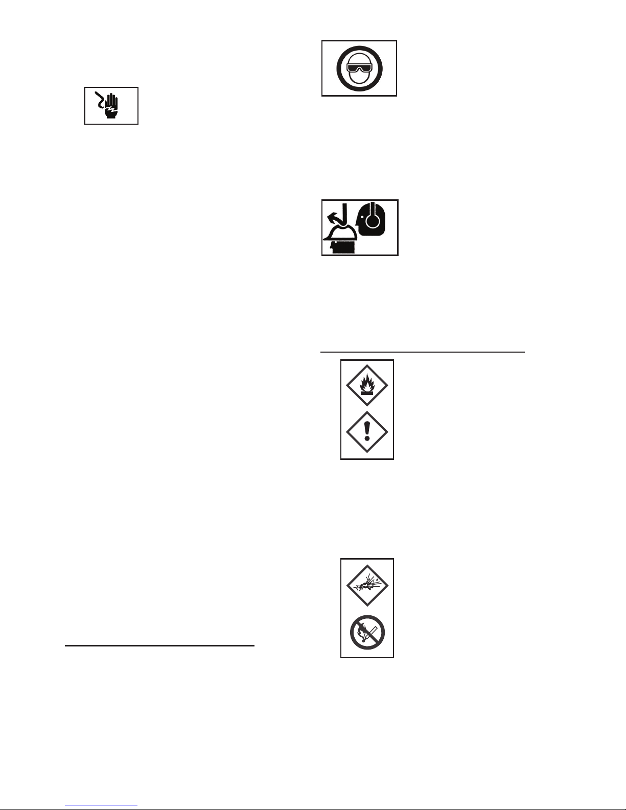
EYE PROTECTION which provides protection against
flying particles both from the FRONT and SIDE should
always be worn by the tool operator and others in the
work area when loading, operating or servicing this tool.
Eye protection is required to guard against flying
fasteners and debris, which could cause severe eye
injury. The employer and/or user must ensure that proper
eye protection is worn.
Eye protection in accordance with
89/686/EEC, and with equal or
greater grade than defined in EN166
should be used. However all aspects
of the operators work, environment
and other type/s of machinery being used should also be
considered when selecting any personal protection
equipment.
Note: Non-side shielded spectacles and face shields
alone do not provide adequate protection.
CAUTION: ADDITIONAL SAFETY PROTECTION may be
required in some environments. For
example, the working area may
include exposure to noise levels that
can lead to hearing damage. The
employer and user should ensure
that any necessary hearing protection is provided and
used by the operator and others in the work area. Some
environments will require the use of head protection
equipment. When required, the employer and user must
ensure that head protection is used.
SAFETY PRECAUTIONS – GAS TOOLS
Be careful of ignition
and explosions.
This tool must not be used in a
combustible environment or in the
presence of flammable liquids or
gases. This tool produces hot exhaust
gases that may ignite flammable
materials and produces sparks. Since
sparks may fly during nailing, it is dangerous to use
this tool near lacquer, paint, benzine, thinner,
gasoline, gas, adhesives and similar inflammable
substances, as they may ignite or explode. Under no
circumstances should this tool be used in the
vicinity of such inflammable material.
Explosion and fire hazard.
The fuel cell is an aerosol dispenser
with flammable contents. It is a
pressured container and the
propellant will remain in the fuel cell.
Failure to follow instructions may
result in explosion or fire. Keep the
power tool, fuel cells and battery
away from sunshine and from temperatures
exceeding 50°C (120°F). The fuel cell and/or battery
may burst, releasing flammable gas. Do not pierce
or burn the container, even after use. Do not
incinerate, refill, reclaim or recycle the fuel cell. Do
not spray on to a naked flame or any incandescent
material.
●
●
●
Page 9
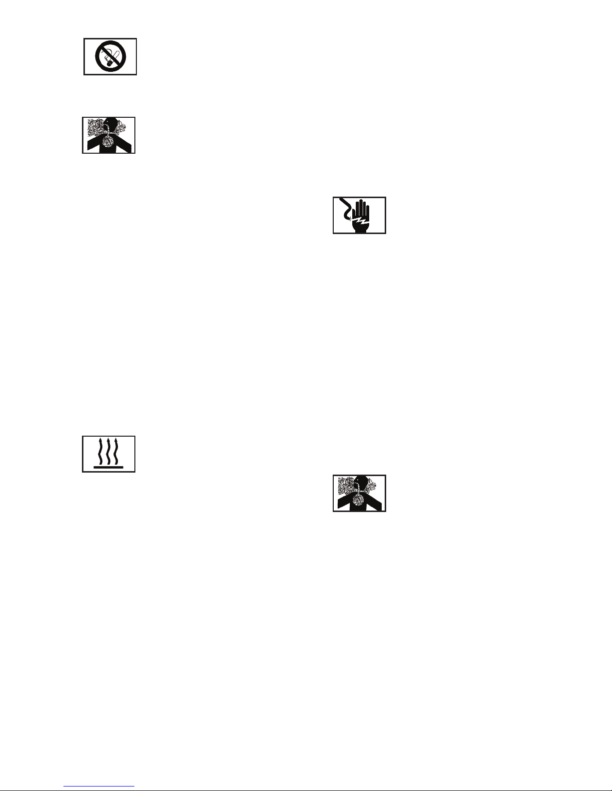
Keep away from ignition sources –
no smoking. Keep out of reach of
children.
● Make sure you read and follow the instructions in
‘Additional Safety Equipment’ detailed above.
Only use outside or in well ventilated
areas.
This tool exhausts carbon monoxide
which are a danger to health when inhaled. This tool
must not be used in enclosed or poorly ventilated
areas. Do not inhale.
● Before using the power tool, check the contact arm.
The contact arm and chamber work in conjunction
for this device to operate. Before using the power
tool, make sure that the contact arm operates
properly. Without nails, fuel cell and battery loaded
into the power tool, check the following- pull the
magazine feeder latch back to disengage the nail
lockout and, with the device facing upward, press
down the contact arm then confirm that the it
securely returns to its original position. If the
contact arm operates abnormally, do not use the
power tool until it has been inspected and repaired.
The contact arm operation becomes especially
heavy in low temperatures and drive operations may
not function. When pulling back the feeder knob, the
contact arm must move smoothly. Furthermore, the
contact arm must never be modified or removed.
Do not touch around the exhaust
outlet.
This tool produces hot exhaust
gases that may ignite flammable materials.
The contact arm and nose will become hot when
in use and get hotter after prolonged or rapid use.
Do not touch with bare hands.
● Disconnect the battery and fuel cell and take out
any nails left in the magazine after use. Disconnect
the battery and fuel cell from the tool before doing
tool maintenance, cleaning a jammed fastener,
leaving the work area, moving the tool to another
location, or after use. It is very dangerous if a nail is
fired by mistake.
● The operating environment for this device is
between 0°C (32°F) and 40°C (104°F) so ensure that
use is within this temperature range. The device
may fail to operate below 0°C (32°F) or above 40°C
(104°F).
● Always charge the battery at an ambient
temperature of 0–40°C.
● A temperature of less than 0°C will result in over
charging, which is dangerous. The battery cannot
be charged at a temperature greater than 40°C. The
most suitable temperature for charging is that of 20–
25°C.
● Do not use the charger continuously. When one
charge is complete, leave the charger for about 15
minutes before beginning the next charge.
● Do not allow foreign matter to enter the hole where
the rechargeable battery fits.
● Never disassemble the rechargeable battery or
charger.
Never short-circuit the rechargeable
battery.
Short-circuiting the battery will
cause a great electric current and the battery will
overheat. This will result in the burning of, or
damage to the battery.
● Do not dispose of the battery in fire. If the battery is
burnt, it may explode.
● Using an exhausted battery will damage the
charger.
● As soon as the post-charging battery life becomes
too short for practical use, recycle according to
your local legislation.
● Do not insert objects into the air ventilation slots of
the charger. Inserting metal or flammable objects
into the charger’s air ventilation slots will result in
an electrical shock hazard or damage to the
charger.
Do not inhale its contents.
In case of inhalation, the person
aected should be taken into the
open air and brought into a comfortable position.
● Expanding gases cause low temperatures. Fluid
gases might cause injuries when coming into
contact with skin or eyes. In case of contact with
skin, wash the contact surface carefully with warm
water and soap and apply a skin cream when dry. In
case of contact with eyes, rinse the open eyes
under running water. Contact a doctor if necessary.
● Store fuel cells in a well ventilated area.
Do not store above 50°C (120°F) (for example in
direct sunlight or in a vehicle). Do not expose to an
open flame and sparks. Do not puncture or open the
fuel cell. Do not refill, reclaim or recycle the fuel cell.
Dispose of according to local regulations for aerosol
products. Do not dispose of fuel cell with other
scrap for recycling. Keep out of reach of children.
●
●
●
●
Page 10

TRANSPORTATION
● Shipment via mail is not allowed.
● Transportation of small quantities for own use in a
private car is allowed without shipping papers and
emergency card.
● Observe temperature limit of 50°C (120°F).
STORAGE
● Do not store in passages, entry halls, near doors and
exits or in attics.
● Ensure the tool, gas cell and battery are all stored in
accordance with local Fire Safety Regulations
● Observe local regulations about storage, handling
and transportation of aerosol products and
according to TRG300(D). International regulations
are established according to ADR/RID; IATA-DGR;
IMDG-Code
● Fuel Cell transportation & storage. According to
GGVS-ADR, no special licence is required for the
transportation of fuel cells.
Road/Rail: see GGVS-ADR/RID CI.2/ITEM 10B2
Seafreight: see IMDG CI.9/P.9022/EmS No. 2-13
Air/IATA-DGR: see CI.2/Risk Gr.3/Packinstr. 203 /
max weight per shipment 75kg / cargo 150 kg
Note: Goods must be accompanied by transport
emergency card for road UN No. 1950 (Emergency
CI.2 GGVS/ADR, Rn.. No. 2201, Item IB02)
Transportation of small quantities for own use in a
private car is allowed without shipping papers and
emergency card.
● Sales booths should not be close to exits.
● A fire extinguisher of 6 kg, class A, B, or C must be
available.
● Packages should be stacked up in a safe manner,
so that they don’t fall to the ground.
● Store rooms must not take more than 20 m2 of room
surface.
● Do not store together with pyrotechnical goods.
● The quantity stored in sales rooms should not
exceed daily sales.
● Tools with an open flame or high temperature must
not be operated near fuel cells.
● Fuel cells must not be displayed in shop windows.
CHARGING THE BATTERY
Before using the tool, charge the battery as follows:
1. Insert the battery into the charger:
Insert the battery firmly into the rear of the magazine,
making sure that it is inserted the correct way around.
Do not force the battery - check the rotation (Fig. 2).
CAUTION
The 9B12073R-U charger purose designed for these
batteries and should not be used to charge other types.
It is possible that other batteries other than those
specified will fit into the charger and some of them may
light up the charging light.
However, this may cause permanent damage to both the
charger and the battery.
2. Plug the power cord into the mains supply. Connecting
the power cord will turn on the charger (the charging
indicator light will then show).
CAUTION
If the charging indicator light does not show, pull out the
power cord and check the battery is mounted correctly
in the charger.
About 60 minutes is required to fully charge the battery
at a temperature of about 20°C. The charging light will
go o to indicate that the battery is fully charged.
The battery charging time becomes longer when the
temperature is low or if the voltage of the power source
is too low.
If the charging indicator light does not go o even after
more than 120 minutes have elapsed, stop the charging
and contact your BOSTITCH AUTHORIZED SERVICE
CENTER.
CAUTION
If the battery is heated due to direct sunlight, etc., just
after operation, the charging indicator may not light up.
If this occurs, cool the battery first, then start charging
again.
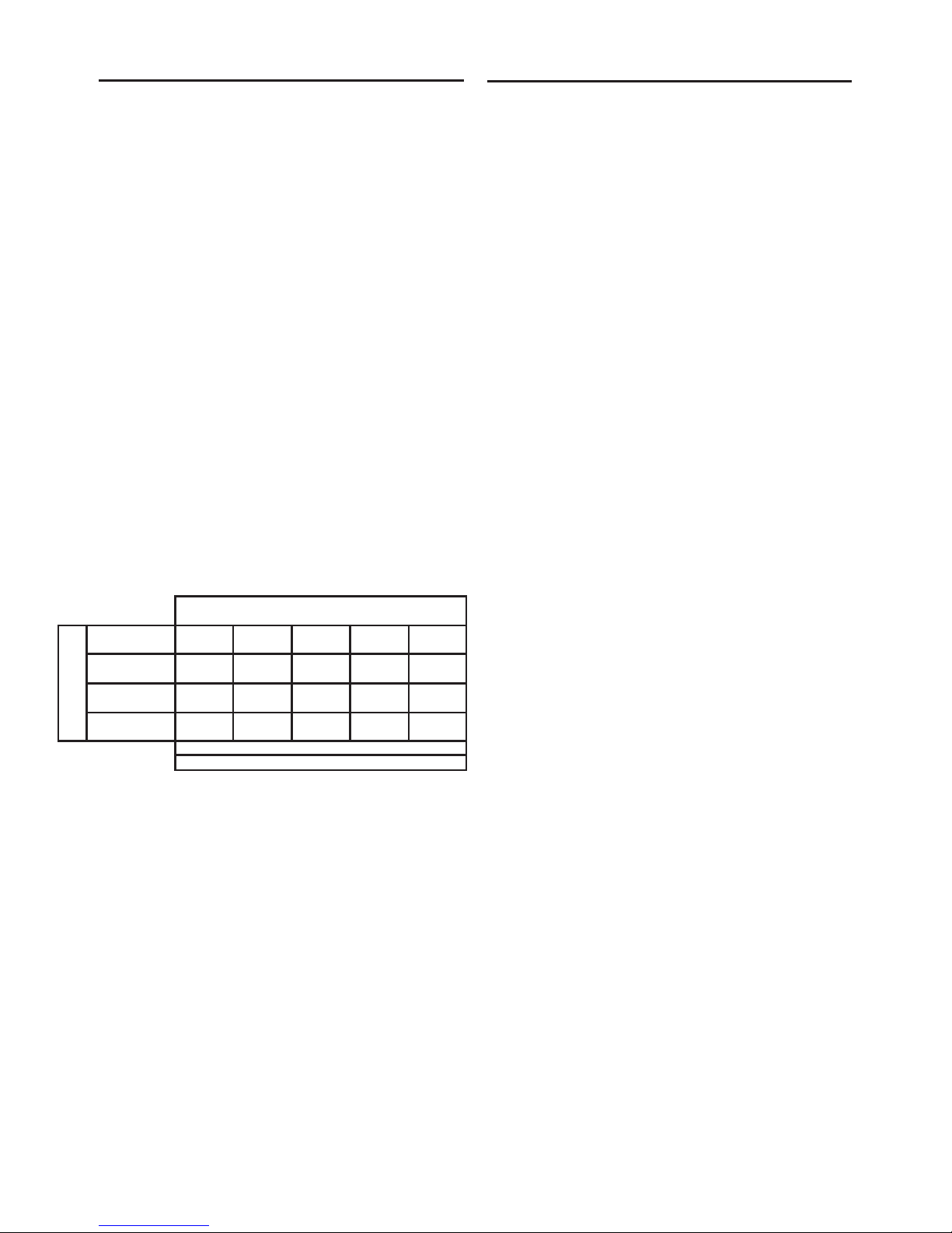
Recharging time: Table 1 shows the recharging time
required according to the type of battery.
Table 1: Recharging time (approx. mins) at 20°C
Battery Battery Capacity (Ah)
voltage (V) 1.4 Ah
7.2V 9B12072R-EU 60 mins.
Page 11

NOTE: The recharging time may vary according to the
ambient temperature.
3. Disconnect the charger power cord.
4. Hold the charger firmly and pull out the battery
NOTE: After charging, pull out batteries from the charger
first, and store properly.. Do not store the batteries in the
charger .
POWER SAVING MODE
If the tool has not been used for about an hour with the
battery still installed, the Power Saving Mode turns on
to minimize unnecessary consumption of battery power.
Power Saving Mode is also activated when the battery
power is extremely low or there’s a fault with the
machine, so please pay attention to the battery indicator
light after reactivating the tool. This is done by removing
the battery and reinstalling it).
2. Insert fuel cell into the tool
i. Pulling the latch and open the cell cover (Fig. 6).
ii. Insert the fuel cell into the tool (Fig. 7).
iii.Insert the stem of fuel cell into the hole of adaptor (Fig.
8).
iv. Close the cell cover.
3. Load nails (see part 5 below)
PREPARING TO USE THE TOOL
Make sure you have read and understood all the
warnings listed in this manual before proceeding to use
the tool
● When fitting fuel or batteries to the tool, the fastener
discharge area of the tool should be pointed away
from the operator and others in the working area.
Place the discharge area of the tool over a test
piece of material of sucient thickness to fully
accommodate the dimensions of the fastener to be
driven. With hands clear of the trigger and trip
mechanism and with limbs and body clear of the
discharge area, the fuel cell and battery may now
be connected.
● Do not pull the trigger or depress the safety trip
while connecting the fuel cell and battery. The tool
could cycle, possibly causing injury.
SAFETY INSTRUCTIONS FOR
LOADING THE TOOL
When loading the tool:
1. Never place a hand or any part of the body in fastener
discharge area of the tool;
2. Never point the tool at self or anyone else.
3. Do not pull the trigger or depress the safety trip as
accidental actuation may occur, possibly causing injury.
Note: See the technical specifications in the front of this
manual for specific loading instructions and dimensions
of recommended fasteners.
SAFETY INSTRUCTIONS FOR TOOL
OPERATION
Always handle the tool with care:
● Never engage in horseplay;
● Never pull the trigger unless the nose is directed
towards the work.
● Keep others at a safe distance from the tool while
the tool is in operation, as accidental actuation may
occur, possibly causing injury.
● The operator must not hold the trigger pulled on
safety trip tools except during fastening operation,
as serious injury could result if the trip accidentally
contacts someone or something, causing the tool to
cycle.
● Keep hands and body away from the discharge area
of the tool. A safety trip tool may bounce from the
recoil of driving a fastener and an unwanted second
fastener may be driven possibly causing injury.
● Check operation of the safety trip mechanism
frequently. Do not use the tool if the contact arm is
not working correctly, as accidental driving of a
fastener may result. Do not interfere with the proper
operation of the safety trip mechanism.
● Do not drive fasteners on top of other fasteners as
this may cause deflection of the fastener, which
could cause injury.
● Do not drive fasteners close to the edge of the work
piece as the wood may split allowing the fastener
to be deflected, possibly causing injury.
Page 12

SAFETY INSTRUCTIONS FOR TOOL
MAINTENANCE
When working on gas tools, pay attention to the
warnings in this manual and on the tool itself and use
extra care when evaluating problem tools.
To prevent accidental actuation and possible injury,
always disconnect the battery and fuel cell:
1. Before making adjustments.
2. When servicing the tool.
3. When clearing a jam.
4. When tool is not in use.
5. When moving to a dierent work area, as accidental
actuation may occur, possibly causing injury.
Check that the tool is functioning correctly by applying
the nose to a piece of scrap wood and pulling the trigger
once or twice.
TOOL OPERATION
PREPARATION PRIOR TO OPERATION
Do not store the tool, fuel cell and battery in a cold
weather environment. Keep the tool, fuel cell and battery
in a warm area until beginning the work.
● If the tool, fuel cell and battery are already cold,
bring them in to a warm area and allow them to
warm up before use.
● Observe the temperature limit of 50°C (120°F).
● Do not expose to an open flame and sparks.
● This tool may not drive completely when;
- at low temperature, the fuel cell loses the required
propellant force,
-high temperature can aect the performance of the
tool .
● Do not use the tool in the rain or where excessive
moisture is present.
● This tool is not recommended for use at altitudes
above 1500m (5000ft), or in temperatures below 0°C
(30°F).
1. FUEL CELL
To attach the metering valve to a fuel cell:
1. Separate the metering valve and the cap from the gas
cartridge (Fig. 3a).
2. Press forwards (stem side) and then downwards on
the front side of the metering valve (Fig. 3b).
3. Press downwards on the rear of the metering valve
until it seals (Fig. 3c).
To check the metering valve is correctly fitted:
Press the metering valve stem on fuel cell two or three
times against a stationary object and release. If gas is
not dispersed, fuel cell is empty and needs to be
replaced.
OBSERVE SAFETY REGULATIONS
CAUTION: If the gas leaks from the metering valve or the
gas cartridge after you have attached the metering
valve, replace with a new metering valve.
Do not attempt to reuse the metering valve- replace it
with each fuel cell used.
2. BATTERY
You must charge the battery before use- see previous
section ‘CHARGING THE BATTERY’.
3. SAFETY CHECK
● Unauthorised persons (including children) must be
kept away from the equipment.
● Wear eye protection.
● Check the retaining screws which fix the top cover,
etc. for tightness. Check the tool for defective or
rusty parts.
● Check whether or not the contact arm works
correctly without nails, fuel cell and battery fitted in
the tool. Also check whether or not any dirt has
adhered to the moving parts of the contact arm.
● Ensure you have read and understood all the
relevant safety instructions in this manual before
proceeding..
4. TOOL OPERATION: BEFORE USE
1. Insert battery into the handle of the tool (Fig. 4)
Note: Do not operate the contact arm or trigger while
installing the battery.
-Make sure the battery indicator light is flashing GREEN
(Fig. 5).
-If the battery indicator light is flashing RED, the battery
doesn’t have enough power and needs to be charged.
BATTERY INDICATOR LIGHT
● Flashing GREEN: Enough power remaining (The light
becomes steady during operation).
● Flashing RED: Insucient power remaining
● OFF (No light visible): The battery is flat. Charge the
battery.
Page 13

2. Insert the fuel cell into the tool
i. Pull the latch and open the fuel cell cover (Fig. 6).
ii. Insert the fuel cell into the tool (Fig. 7), making sure
that the stem of the fuel cell lines up correctly with the
hole in the adaptor (Fig. 8).
iii. Close the cover (Fig. 9).
5. LOADING THE TOOL
CAUTION: When loading nails into tool:
● Do not depress trigger
● Do not depress contact arm
● Keep your face, hands, feet and other body parts,
as well as those of other persons away from the
nose to avoid possible injury during loading.
MODEL: GF33PT-E, GF28WW-E, GCN40T-E
1. Insert nail strip into rear of magazine (Fig. 9).
2. Slide the nail strip forward in the magazine (Fig. 10).
3. Pull the nail feeder (B) back to engage the feeder knob
to the nail strip (Fig. 11).
NOTE Use nail strip of more than 10 nails.
Removing the nails:
1. Pull the feeder knob backward (Fig. 12).
2. Return the feeder knob forward quietly while pushing
the nail feeder (B).
3. Pull out nails from the back of the magazine (Fig.13).
CAUTION: To prevent unintentional operation, never
touch the trigger or place the top end of the contact arm
on a work bench on floor. Also, never face the nail outlet
toward any part of a person.
NAIL SELECTION: GCN40T-E
To ensure correct fixing when nailing wood to concrete
or thin steel to concrete, please use the fastener length
as indicated below:
Wood to concrete: choose nail for 15-20mm intrusion
depth into the concrete.
Thin steel sheet to concrete: choose nail to secure 1220mm intrusion depth into the concrete.
6. USING THE NAILER
CAUTION
● Squeeze the contact arm when drivng a nail,
otherwise the piston can not return correctly.
● Using the tool for an extended period may lead to oil
around the exhaust outlet or nose, resulting in
spattering.
● To ensure that the material to be nailed stays clean,
wipe o any oil that gets on the tool.
CYCLE RATES
These tools are designed to operate up to the following
cycle rates:
Intermittent Operation – 2 to 3 nails per second
Continuous Operation – 1000 nails per hour
Exceeding these rates could cause the tool to overheat,
resulting in loss of performance or damage to tool
components. By using the nailer at its recommended
cycle rate, you will be able to drive several thousand
nails in a typical working day.
SAFETY TRIP
These tools are supplied fitted with a sequential safety
trip and are marked with an inverted equilateral triangle
(▼). Do not attempt to use a tool marked in this way if
the safety trip is missing or appears damaged.
The sequential trip requires the operator to hold the tool
against the work with the safety trip depressed before
pulling the trigger. In order to drive additional fasteners,
the trigger must be released and the tool lifted away
from the work, before repeating.
This makes accurate fastener placement easier, for
instance on framing, toe nailing and crating applications.
The sequential trip allows exact fastener location
without the possibility of driving a second fastener on
recoil. The sequential trip tool has a positive safety
advantage because it will not accidentally drive a
fastener if the tool is contacted against the work or
anything else, while the operator is holding the trigger.
FASTENER LOCKOUT (GF33PT / GF28WW)
These tools employ a mechanism to prevent dry firing of
the tool.
When the magazine is not loaded with nails or when the
remaining number of nails becomes less than 10, the
contact arm cannot operate and the tool will not fire.
Wood Suitable Intrusion Depth
Thickness Nail Length Into Concrete
10mm 30mm 20mm approx.
15mm 35mm 20mm approx.
20mm 40mm 20mm approx.
Page 14

TOOL OPERATION CHECK
SEQUENTIAL TRIP OPERATION
A) Without touching the trigger, press the contact arm
against the work surface.
THE TOOL MUST NOT CYCLE.
B) Hold the tool o the work surface and, avoiding to
point the tool at yourself or others, pull the trigger.
THE TOOL MUST NOT CYCLE.
C) With the tool o the work surface, pull the trigger.
Press the safety trip against the work surface
THE TOOL MUST NOT CYCLE.
D) Without touching the trigger, press the safety trip
against the work surface then pull the trigger.
THE TOOL MUST CYCLE.
TOOL USE
Having checked that the tool is working properly, press
the nose against the work piece and pull the trigger.
Check whether the fastener has been driven as required
(Fig. 14).
ADJUSTING THE NAILING DEPTH
To ensure that each nail penetrates to the same depth, be
sure that the tool is always held firmly against the workpiece.
If nails are driven too deep or shallow into the workpiece,
adjust the nailing in the following order:
1. Remove the fuel cell and the battery from the tool (Fig. 15).
2. If nails are driven too deeply, move the contact arm forward
(Fig. 16). If nails are driven too shallow, move the contact arm
backward (Fig. 17).
3. Stop moving the contact arm when a suitable position is
reached for a nailing test.
4. Connect the fuel cell and the battery to the tool.
ALWAYS WEAR EYE PROTECTION.
Perform a nailing test.
5. Remove the fuel cell and the battery from the tool.
6. Make further adjustments until the drive depth is correct,
testing after each adjustment.
7. UTILITY HOOK (GF28WW / GF33PT)
These tools have a utility hook installed in the magazine
which can be folded back for easier tool use. To adjust
the hook, simply rotate to the desired position. .
8. USING THE NO-MAR TIP (GNC40T)
If you need to protect the surface of the workpiece
against scratches or markings made by the contact arm,
a No-Mar Tip can be fitted to the tool.
1. First, remove the fuel cell and the battery from the
nailer.
2. Put on the No-Mar Tip as shown in Fig. 18 depending
on your tool model.
3. The tip is marked to indicate the exit point of the nail,
making alignment easier.
To remove the tip, pull it o in the reverse order of
attachment (Fig. 19).
MAINTENANCE & TROUBLESHOOTING
Remove the fuel cell and battery from the tool and
completely empty the magazine before starting
maintenance or repairs. Read and understand the
warnings in this manual, in the Tool Technical Data and
on the tool itself and use extra care when evaluating
problem tools.
Bostitch replacement parts are recommended. Do not
use modified parts or parts that will not give
performance equal to the original equipment.
CAUTION: Be sure to remove the battery and fuel cell
during clearing jams, inspection, maintenance and
cleaning.
JAM CLEARANCE
If nails are jammed in firing head, remove it, and adjust the
nailing in the following order.
GF28WW / GF33PT
1. Remove the fuel cell and the battery from the Nailer.
2. Lock follower back in magazine and remove fasteners.
3. GF28WW / GFD33PT: Remove the bolts with wrench (Fig.
20).
3. GNC 40T: Undo the magazine catch (Fig. 21).
4. Pull magazine away from the firing head, and clear jam
(Fig. 22 & 23).
5. Connect the fuel cell and the battery to the Nailer.
INSPECTING THE MAGAZINE
1. First, remove the fuel cell and the battery from
the nailer.
2. Clean the magazine. Remove paper chips or wooden
chips which may have accumulated in the magazine.
Lubricate it with Bostitch gas finish nailer lubricant (Fig.
24).
Page 15

CHECKING MOUNTING SCREWS
At regular intervals, check every part for loose mounting
screws and tighten any loose screws found. Operating
the tool with loose screws will can be hazardous.
INSPECTING THE CONTACT ARM
Check if the contact arm can slide smoothly.
Clean the sliding area of the contact arm and use the
provided oil for lubrication from time to time.
This will enable a smooth operation and simultaneously
help to prevent the formation of rust.
PREPARATION FOR STORAGE
● When not in use for an extended period, apply a thin
coat of the lubricant to the steel parts to avoid rust.
● Do not store the nailer in a cold weather
environment. When not in use, the tool should be
stored in a warm and dry place.
● Keep out of reach of children.
● Refer to all instructions in the previous ‘Storage’
section of this manual.
SERVICE PARTS LIST
CAUTION: Repair, modification and inspection of
Bostitch Power Tools must be carried out by a Bostitch
Authorised Service Center.
The Parts List supplied with this tool will be helpful if
presented with the tool to the Bostitch Authorised
Service Center when requesting repair or other
maintenance.
In the operation and maintenance of power tools, the
safety regulations and standards prescribed in each
country must be observed.
MODIFICATIONS
Stanley Bostitch tools are constantly being improved
and modified to incorporate the latest technological
advancements.
Accordingly, some parts may be changed without prior
notice.
APPLICABLE LUBRICANTS
Use BOSTITCH Gas Nailer lubricant.
Do not use detergent oil or additives: these lubricants
will harm the O-rings and other rubber parts and will
cause the tool to malfunction.
NOISE AND VIBRATION DATA
NOISE EMISSION (See Tool Technical Data)
The characteristic noise values for the tool have been
determined in accordance with EN 12549 - “Acoustics Noise test code for fastener driving tools - Engineering
Method."
These values are tool related characteristic values and
do not represent the noise development at the point of
use. Noise development at the point of use will depend
for example on the working environment, the work piece,
the work piece support and the number of driving
operations, etc.
Depending on the conditions at the workplace and the
form of the work piece, individual noise attenuation
measures may need to be carried out, such as placing
work pieces on sound damping supports, preventing
work piece vibration by means of clamping or covering,
adjusting to the minimum air pressure required for the
job, etc.
INFORMATION ON VIBRATION (see Tool Technical
Data)
The characteristic vibration value for the tool has been
determined in accordance with ISO/WD 8662-11
"Measurement of vibration in hand held power tools Part 11 Fastener Driving Tools".
This value is a tool related characteristic and does not
represent the influence on the hand-arm system when
using the tool. An influence on the hand-arm system
when using the tool will depend for example on the
gripping force, the contact force, the working direction,
the adjustment of the compressed air supply, the work
piece, the work piece support, etc.
Page 16
MAINTENANCE INTERVALS
Maintenance intervals for the tools can vary
depending upon the environment the tool is being
operated in, the application it is being used for and
the volume of nails that are being driven. For
example, if it is being used in dirty and dusty
conditions for high volume nailing, maintenance will
be required more regularly rather than in clean
conditions with low volumes of nails.
The chart that follows has been produced as a guide
to help you establish the maintenance intervals for
the tools. If you experience an excessive build up of
debris within the tool between cleans, reduce the
maintenance intervals. If the tool does not require
cleaning within the schedule you have established,
then you may be able to extend the maintenance
intervals. If you have any questions regarding the
above please contact your local distributor for help
and advice.
Maintenance Intervals GF33PT-E / GF28WW-E / GCN40T-E:
FILTER CLEANING
The ‘fig’ references for this are supplied on the
seperate sheet ‘Filter Cleaning / Tool Cleaning &
Lubrication Guide’ for easy reference.
When working on the tools, do not lose any parts of
the disassembled tool and use only genuine Stanley
Bostitch parts to ensure proper tool operation and
safety.
1. Before cleaning, check that the tool has cooled
down completely, and then remove all nails, the fuel
cell and the battery from the tool (Fig. 25).
2. Using a 4mm hex key, remove and retain the hex
socket head bolt (Fig. 26) (M5 x 14).
3. Tilt back the top cover (Fig. 27).
4. Remove the filter from inside the top cover (Fig. 28).
5. Remove the dust and rubbish from the filter with
Bostitch cleaner [SB-TC1]. Ensure that the filter is dry
and free from contamination. Replace the filter and
filter cover (Fig. 29).
6. Set the motor lead wire and the spark plug lead
wire (Fig. 30).
A) Check that the lead wires are inside the rib.
B) Check that the lead wires are not trapped by the
cover.
C) Check the position of the lead wire setting position
7. Check that the filter isn’t damaged. If damaged,
replace the filter with a new one (part no. 192103)
making sure none of the leads are trapped (Fig. 31).
8. Replace the top cover, ensuring that none of the
leads are trapped (Fig. 32).
9. Replace the socket head bolt (Fig. 33).
10. Always carry out 5-10 test cycles of the tool on
waste material before using on a finished surface to
expel any cleaning material residue [SB-TC1] (Fig.
34).
Number of Days Between
Maintenance Operations
Very dirty & dusty
3-4 3-4 3-4 3-4 3-4
Dusty 10-14 10-14 10-14 3-4 3-4
Moderate 30-45 30-45 30-45 10-14 10-14
Clean 45-60 45-60 45-60 30-45 30-45
12468+
Weekly Nail Usage [x1000]
Operating
Environment
Page 17

CLEANING & LUBRICATION
Make sure that you have read and understood all
safety warnings and cleaning procedures before
attempting to operate or clean this tool. Failure to do
so may result in serious injury.
WARNING: Make sure that the 4 hex socket head
bolts are securely attached to the cylinder head
before operating the tool. Loose or missing bolts
may cause leakage of burning gases causing injury
to the user and damage to the tool and property.
1. Before cleaning, check that the tool has cooled
down completely, and then remove all nails, the fuel
cell and the battery from the tool (Fig. 35).
2. Using a 4mm hex key, remove and retain the hex
socket head bolt (Fig. 36) (M5 x 14).
3. Tilt back the top cover (Fig. 37).
4. Remove the filter assembly on the cylinder head
(Fig. 38).
5. Unplug the spark plug connection from the spark
plug (Fig. 39) and carefully disconnect the motor
lead (Fig. 40).
6. Using a 4mm hex key, remove and retain the 4 hex
socket head bolts in the cylinder head (Fig. 41) (M54
x 20, 4pcs).
7. Gently lift the cylinder head away from the
combustion chamber (Fig. 42).
8. Ensuring you do not damage the fan blades,
carefully remove the o-ring from the fan (Fig. 43 &
44).
9. Using a dry cloth, clean and remove all deposits
from the o-ring. Inspect the O-ring for damage and
if necessary, replace it (part no. 192114) (Fig. 45).
10. Clean the cylinder head using brake cleaner,
paying particular attention to the spark plug. (Fig. 46)
11. A small brush may be useful to help release
some debris. You may need to repeat this 2 or 3
times until clean (Fig. 47).
12. Replace the o-ring on the cylinder head (Fig. 48).
13. Lubricate the o-ring using Bostitch gas nailer
lubricant (part no. SB-20CL) (Fig. 49).
14. Spray brake cleaner into the cylinder to loosen
any residue (Fig. 50).
15. Using a blunt instrument (e.g. a screwdriver
handle), push down the piston (Fig. 51).
16. Holding the tool upside down, spray brake
cleaner into the combustion chamber and the
chamber head, ensuring any residue falls back out
of the tool. You may need to do this 2 or 3 times using
a small rush to loosen some of the more stubborn
residue (Fig. 52).
17. Using a screwdriver or similar implement, push
the driver blade back into the tool (Fig. 53).
18. Pull back the nail feeder to disengage the tool
lockout and press down the contact arm on a hard
surface. Using the Bostitch lubricant (part no. SB20CL), oil around the outside groove in the
combustion chamber, where the o-ring is located
(Fig. 54).
19. Ensuring the O-ring is evenly seated on the
cylinder head, carefully locate the cylinder head
back on top of the tool, taking care not to damage
the fan blade (Fig. 55).
20. Depressing the body, assemble the cylinder head
and confirm the o-ring is not trapped. Set the 4
socket head bolts (Fig. 56).
21. Put the 4 socket head bolts back to their original
positions using a 4mm hex key(put one of the 4
socket head bolts through the wiring plate). Tighten
the head bolts while securing the wire to the wiring
plate (Fig. 57 & 58).
22. Check the o-ring is correctly seated by pulling
back the nail feeder and depressing the contact arm
(Fig. 59).
23. Reconnect the motor lead wire and then the
spark plug lead wire (Fig. 60 & 61).
24. Set the motor lead wire and the spark plug lead
wire (Fig. 62).
Page 18

A) Check that the lead wires are inside the rib.
B) Check that the lead wires are not trapped by the
cover.
C) Check the position of the lead wire setting
position
25. Replace the filter assembly, ensuring that none
of the leads are trapped (Fig. 63).
26. Replace the top cover, ensuring that none of the
leads are trapped (Fig. 64).
27. Replace the socket head bolt (Fig. 65).
28. Confirm that the tip of all 4 of the socket head bolt
is sticking out of the housing (Fig. 66).
29. Always carry out 5-10 test cycles of the tool on
waste material before using on a finished surface to
expel any cleaning material residue (Fig. 67).
ACTION WHY HOW
Clean magazine and feeder mechanism. Prevent a jam. Blow clean daily.
Keep contact arm working properly. Promote operator safety and Blow clean daily.
ecient Nailer operation.
Maintenance chart
Page 19

A Length mm. K Magazine capacity
B Height mm. L Working Ambient Temprature
C Width mm. M Charger Ref
D Weight Kg. N Input Power Source
E Noise LPA 1s d O Charging Time in Minutes at 20ºc (70f)
F Noise LWA 1 s d P Charging Voltage
G Vibration m/s2 Q Charging Current
H Fastener Name R Weight Kg.
I(a) Dimensions mm. S Battery Weight Kg.
I(b) Dimensions mm. T Battery Type
J Head/crown U Fuel Cell - Liquid Hydrocarbon:propane/butane
Operator troubleshooting
PROBLEM CHECK METHOD CORRECTION
Nailer operates, but no nail is driven. Check for a jam. Clear the jam.
Check function of the nail feeder. Clean and lubricate if required.
Ribbon spring weakened or damaged? Replace ribbon spring.
Check the correct nails are being used. Use only recommended nails.
Check if the driver blade piston is Remove the battery, fuel cell & nails from the tool
not returned to the top position and, using a thin piece of metal of screwdriver
100mm long (not included), insert into the contact
arm (Fig 58) and push the bar to the top position.
Skipping nails. Check for proper nails. Use only recommended nails.
Intermittent feed. Check function of nail feeder. Clean and lubricate.
Ribbon spring weakened or damaged? Replace ribbon spring.
Nail feeder worn or damaged? Replace nail feeder.
Check for returning of piston. Pull the trigger firmly and for about 0.5 sec after combustion.
Too low temperature, warm up
fuel cell under 50°C (120°F).
Check for moving of piston smoothly. Contact Bostitch for replacement.
Replace piston ring.
Replace piston.
Replace cylinder piston ring.
Nails jam. Check for proper nails. Use only recommended nails.
Driven nail is bent. Driver blade worn? Contact Bostitch for replacement.
Nail feeder worn or damaged? Replace nail feeder.
The operation of the contact arm Contact arm bent? Contact Bostitch for replacement.
not smooth. Check contact arm’s moving track for Contact Bostitch for replacement.
debris.
Fan is working, light indicator Check for returning of piston. Push the contact arm all the way.
shows GREEN yet it doesn’t drive Too low temperature, warm up
a nail or operation unstable. fuel cell under 50°C (120°F).
Check fuel cell, insucient? Exchange it with a new fuel cell.
Check spark plug wire, worn out? Contact Bostitch for replacement.
Check spark plug, grease or debris? Contact Bostitch for replacement.
Check filter, clogged? Clean in accordance with the
maintenance chart.
Fan does not operate when push Magazine empty. Load more nails in the magazine.
lever is pressed. Note the color of the light indicator. If red: charge the battery.
If green: Contact Bostitch for replacement.
Unable to charge battery. Check the electrical cord.
Technical Data Table Key (See page 2)
Page 20

MANUEL D'UTILISATION ET DE SECURITE
CET OUTIL ELECTRIQUE FONCTIONNE GRACE A
UN DISPOSITIF DE COMBUSTION INTERNE ET
NE DOIT ETRE UTILISE QU'AVEC LES
CARTOUCHES DE COMBUSTIBLE A GAZ FIGURANT DANS LA
LISTE SITUEE DANS CES CONSIGNES DE MANIPULATION.
AVANT D'UTILISER CET OUTIL, TOUS LES UTILISATEURS
DOIVENT ETUDIER CE MANUEL ET LES DONNEES TECHNIQUES
DE L'APPAREIL AFIN DE COMPRENDRE ET DE SUIVRE LES
CONSIGNES DE SECURITE ET LES MISES EN GARDE. VEUILLEZ
CONSERVER CES CONSIGNES AVEC L'OUTIL AFIN DE POUVOIR
VOUS Y REPORTER A L'AVENIR.
SI VOUS AVEZ DES QUESTIONS, VEUILLEZ CONTACTER VOTRE
REPRESENTANT OU DISTRIBUTEUR BOSTITCH.
Les outils Bostitch ont été conçus afin de satisfaire le client par
leur excellence et de permettre une performance maximum
lorsqu'ils sont utilisés avec les attaches de précision Bostitch
fabriquées selon les mêmes standards d'exactitude. Lorsqu'ils
sont utilisés correctement et avec soin, ils fourniront des
prestations ecaces et fiables. Comme avec tout outil électrique,
les consignes du fabricant doivent être suivies si l'on veut obtenir
le meilleur résultat.
NB : Des mesures de sécurité supplémentaires pourraient être
nécessaires dans le cas d'une utilisation particulière de l'outil. Si
vous avez des questions concernant l'outil ou son utilisation,
veuillez contacter votre représentant ou distributeur Bostitch.
NB : Bostitch n'engage pas sa responsabilité quant à la
performance du produit au cas où un quelconque de nos appareils
était utilisé avec des attaches ou des accessoires ne satisfont pas
aux exigences spécifiques établies par les clous, agrafes,
batteries, cartouches de combustible, chargeurs et accessoires
Bostitch.
GARANTIE LIMITEE
Bostitch Inc. garantit à l'acheteur d'origine que ce produit ne
comporte pas de défauts de matériau ou de fabrication, et accepte
de réparer ou de remplacer tout produit défectueux, à sa
discrétion, dans les 90 jours suivant la date d'achat. Cette garantie
n'est pas transférable. Elle ne couvre que les dommages
découlant de défauts matériels ou de fabrication et elle ne couvre
pas les dommages ou le mauvais fonctionnement causés par
l'usure normale de l'outil, la négligence, l'utilisation abusive ou les
accidents.
CETTE GARANTIE REMPLACE TOUTES LES AUTRES
GARANTIES EXPRESSES. TOUTE GARANTIE DE
COMMERCIALISATION OU D'APTITUDE A UNE UTILISATION
PARTICULIERE SE LIMITE A LA DUREE DE LA PRESENTE
GARANTIE. BOSTITCH NE SAURAIT ETRE TENU RESPONSABLE
D'AUCUN DOMMAGE ACCESSOIRE OU INDIRECT.
Certains pays ne permettent pas de limitations quant à la durée
implicite d'une garantie, ou quant à l'exclusion ou la limitation des
dommages accessoires ou indirects. Il est par conséquent
possible que les limitations ou exclusions ci-dessus ne
s'appliquent pas à vous. Cette garantie vous accorde des droits
spécifiques et vous pouvez également bénéficier de droits
supplémentaires, variables de pays à pays et d'état à état. Pour
bénéficier d'une réparation sous garantie, vous devez retourner le
produit à vos frais, accompagné d'une preuve d'achat, au centre
régional de réparations sous garantie de Bostitch.
ACCESSOIRES
Ces outils sont fournis avec les accessoires suivants :
1) chargeur x 1
2) mallette de transport x 1
3) clé hexagonale pour vis M5 x 1
4) mallette de transport x 1
5) batterie x 2
Certains accessoires optionnels sont également vendus
séparément :
1) Cartouches de combustible Code ref:
FC80ML /
FC80ML-HP
2) Bâton de lubrifiant cloueur, 250cc Code ref: SB-20CL
CONSIGNES DE SECURITE GENERALES
Seules les attaches, batteries, cartouches de combustible et
chargeurs qui figurent dans ce mode d'emploi devraient être
utilisés avec l'outil. Pour des raisons de sécurité, l'outil et les
attaches spécifiées doivent être considérés comme constituants
d'un système unique.
Les réparations ne devront être eectuées que par des agents
Bostitch agréés ou autres experts, prenant soin d’appliquer toutes
les mesures de sécurité nécessaires et en respectant les conseils
d’utilisation et les consignes de maintenance présents dans ce
manuel et dans les Données techniques s’appliquant à l’appareil.
NB : Les experts sont les personnes qui, suite à une formation
professionnelle ou à leur expérience, ont acquis une expertise
susante dans le domaine des outils de fixation afin d'être à
même d'évaluer si leur état permet une utilisation en toute sécurité.
EN PLUS DES AUTRES MISES EN GARDE FIGURANT DANS CE
MANUEL, VEUILLEZ RESPECTER LES CONSIGNES DE SECURITE
SUIVANTES :
FR
Page 21

Ne pas jeter les outils électriques usagés avec les ordures
ménagères !
Conformément à la Directive européenne
2002/96/EC & 2006/66/EC relative aux déchets
d'équipements électriques et électroniques/
batteries, et à son implémentation aux termes
dudroit national, les outils électriques/batteries en fin de vie
doivent faire l'objet d'une collecte séparée et doivent être
retournés à un centre de recyclage approprié.
● Respectez votre outil Bostitch en tant qu'outil. Ce n'est pas
un jouet. Ne chahutez pas avec.
● N'utilisez les outils Bostitch que pour les applications pour
lesquelles ils ont été conçus, à savoir : l'encadrement, les
cloisons, les sous-couches de sol et le clouage du bois au
béton (GNC40T uniquement). Les outils GF28WW/GF33PT
ne doivent être utilisés que pour des applications de
fixation de bois à bois.
● Ne pas enfoncer un clou sur un autre clou.
● Ne pas enfoncer un clou sur une surface en métal.
● Ne jamais utiliser l'outil d'une manière susceptible de
diriger l'attache vers l'utilisateur ou vers d'autres
personnes se trouvant dans la zone de travail.
● Ne pas utiliser cet outil comme un marteau.
● Toujours transporter l'outil en utilisant sa poignée. Ne
jamais transporter l'outil en appuyant sur la gâchette.
● Ne pas changer ou modifier cet outil par rapport à sa
conception d'origine ou sa fonction sans l'accord
préalable écrit de Stanley Bostitch.
● Soyez toujours conscient qu'une utilisation erronée ou une
mauvaise manipulation de cet outil pourrait vous causer
des blessures ou en causer aux autres.
● Ne jamais bloquer ou scotcher la gâchette de sécurité en
position de déclenchement.
● Ne jamais laisser traîner un outil muni d'une cartouche de
combustible ou d'une batterie chargée.
● Ne pas utiliser cet outil s'il ne contient pas une ETIQUETTE
D'AVERTISSEMENT lisible.
● Ne pas continuer à utiliser un outil qui ne fonctionne pas
correctement. Veuillez informer votre représentant Stanley
Bostitch le plus proche si votre outil continue à ne pas
fonctionner correctement.
● Pendant l'utilisation, tenez l'outil de manière à éviter les
blessures à la tête ou au corps au cas où les mouvements
de recul de l'outil augmentaient du fait de variations au
niveau de l'alimentation en gaz ou de zones plus dures
situées sur la surface de travail.
● Ne pas utiliser l'appareil près des coins ou du bord des
pièces que vous travaillez. L'appareil pourrait glisser hors
de la surface de travail et entraîner des blessures.
● Retirer la batterie et la cartouche de combustible avant de
transporter l'outil.
● Vérifier que le coupe-circuit de sécurité (s’il existe) et la
gâchette fonctionnent correctement avant chaque
utilisation.
● Aucune partie de l'outil ne doit être démontée ou bloquée,
en particulier le coupe-circuit de sécurité.
● Ne jamais eectuer de « réparations d'urgence » sans
utiliser un équipement approprié.
● Éviter d'aaiblir l'outil en le gravant ou en le perforant.
● Cet outil électrique fonctionne grâce à un dispositif de
combustion interne. Cet outil doit être utilisé uniquement
avec les distributeurs de gaz qui figurent dans la liste se
trouvant dans ces consignes de manipulation.
● Ne jamais laisser des enfants ou des personnes ne
sachant pas s'en servir correctement utiliser cet outil.
● Garder les diérentes pièces dans les endroits corrects.
Ne retirer aucun couvercle ou aucune vis. Gardez-les à
leur place car ils/elles ont leur utilité. De plus, ne jamais
modifier l'outil ou l'utiliser après qu'il ait été modifié.
● Vérifier l'outil avant utilisation. Avant d'utiliser l'outil,
toujours vérifier qu'aucune partie n'est cassée, que toutes
les vis sont bien serrées et qu'aucune partie ne manque ou
n'est rouillée.
● Un excès de travail pourrait entraîner des accidents. Ne
pas faire fonctionner les outils ou les accessoires au-delà
de leur capacité. Un excès de fonctionnement non
seulement diminue la puissance de l'outil mais il peut aussi
s'avérer dangereux.
● Cessez immédiatement d'utiliser l'outil si vous remarquez
des choses anormales ou si l'outil ne fonctionne pas
correctement ; faites inspecter et réparer l'outil.
● Prendre bien soin de l'outil afin d'assurer sa longévité.
Toujours prendre soin de l'outil et le garder propre.
● Il est essentiel d'inspecter l'outil à des intervalles réguliers
afin de l'utiliser en toute sécurité. Inspecter l'outil à
intervalles réguliers afin qu'il puisse toujours être utilisé en
toute sécurité et ecacement.
● Éviter les environnements dangereux. Ne pas exposer
l'outil ou le chargeur à la pluie et ne pas utiliser l'outil ou le
chargeur dans des conditions humides. Faire en sorte que
la surface de travail soit bien éclairée. Ne jamais utiliser
l'outil et le chargeur à proximité de matériaux explosifs ou
inflammables. Ne pas utiliser
●
Page 22
● l'outil et le chargeur en présence de gaz ou de liquides
inflammables.
● Ranger l'outil et le chargeur en position neutre. Lorsque
vous n'utilisez pas l'outil et le chargeur, ils doivent être
rangés dans un endroit sec, en hauteur et hors de la portée
des enfants et des personnes incapables. Ranger l'outil et
le chargeur dans un endroit n'excédant pas 40°C.
Ne pas abîmer le cordon. Ne jamais
transporter le chargeur en le tenant par le
cordon. Ne jamais tirer sur le cordon
d'alimentation pour le débrancher du
secteur. Garder le cordon à l'abri de la chaleur, de l'huile et
des objets coupants.
● Lorsque le chargeur n'est pas utilisé, ou bien pendant qu'il
fait l'objet d'une inspection ou de maintenance, il doit être
débranché du secteur.
● Afin d'éviter le danger, toujours utiliser uniquement le
chargeur spécifié.
● Afin d'éviter les blessures personnelles, n'utiliser que les
accessoires ou attachements recommandés dans ce
manuel ou dans le catalogue Stanley Bostitch.
● Vérifier et confirmer que le cordon d'alimentation et le
boîtier ne sont pas endommagés avant d'utiliser le
chargeur. Si le cordon d'alimentation de ce chargeur ou
son boîtier sont endommagés, le chargeur doit être
retourné au centre de réparations agréé Stanley Bostitch
afin que la pièce endommagée soit remplacée. Seuls les
centres de réparations agréés doivent eectuer ces
réparations. Stanley Bostitch ne sera tenu responsable
d’aucuns dommages ou blessures entraînés par des
personnes non autorisées essayant de réparer l'outil, ou
par une mauvaise manipulation de l'outil.
● Afin d'assurer l'intégrité opérationnelle du design de l'outil
et du chargeur, ne pas retirer les couvercles ou les vis
installés.
● Toujours utiliser le chargeur au voltage indiqué sur la
plaque signalétique.
● Toujours charger la batterie avant utilisation.
● Ne jamais utiliser une batterie autre que celle spécifiée. Ne
pas connecter une pile sèche, une batterie rechargeable
autre que cette spécifiée ou une batterie de voiture à l'outil.
● Ne pas utiliser un transformateur muni d'un survolteur.
● Ne pas charger la batterie à partir d'un moteur, d'un
générateur électrique ou d'une alimentation en courant
continu.
EQUIPEMENT DE SECURITE SUPPLEMENTAIRE
DES LUNETTES DE PROTECTION fournissant une protection
frontale et latérale contre les particules projetées doivent toujours
être portées par l'utilisateur de l'outil et par les autres personnes
présentes autour de la pièce de travail lors du chargement, de
l'utilisation ou de la réparation de l'outil. Les lunettes de protection
sont nécessaires afin de protéger contre les clous ou les débris
projetés qui pourraient causer de sérieuses blessures oculaires.
L'employeur et/ou l'utilisateur doit s'assurer que des lunettes
appropriées soient utilisées.
Il faut utiliser des lunettes de protection
conformes à la Directive 89/686/CEE/CEE et
orant une protection égale ou supérieure
à celle définie par la norme EN166.
Cependant tous les aspects du travail de
l'utilisateur, de son environnement et
d'autres types de machines utilisées doivent également être pris
en compte lors de la sélection de tout équipement de protection.
NB : Les lunettes n'orant pas de protection latérale et les
masques frontaux n'orent pas une protection adéquate.
ATTENTION : UN EQUIPEMENT DE
PROTECTION SUPPLEMENTAIRE
pourrait être nécessaire dans certains
environnements. Par exemple, la zone de
travail peut entraîner une exposition à des
niveaux de bruit susceptibles d'endommager l'audition.
L'employeur et l'utilisateur doivent s'assurer que les protections
auriculaires nécessaires soient fournies et utilisées par la
personne utilisant l'outil dans la zone de travail en question. Un
casque devra aussi être utilisé dans certains environnements.
L'employeur et l'utilisateur doivent s'assurer qu'un casque soit
utilisé si nécessaire
MESURES DE SECURITE – OUTILS A GAZ
Faites attention aux étincelles et aux
explosions.
Cet outil ne doit pas être utilisé dans un
environnement inflammable ou en
présence de gaz ou de liquides
inflammables. Cet outil produit des gaz
d'échappement chauds qui pourraient
enflammer les matériaux inflammables
et produire des étincelles. Parce que les étincelles pourraient
voler pendant le clouage, il est dangereux d'utiliser l'outil à
proximité de laque, de peinture, d'essence, de benzène, de
diluant, de gaz, de produits adhésifs et autres substances
inflammables similaires, car elles pourraient s'enflammer ou
exploser. Cet outil ne doit en aucun cas être utilisé à
proximité de telles substances inflammables.
●
●
Page 23
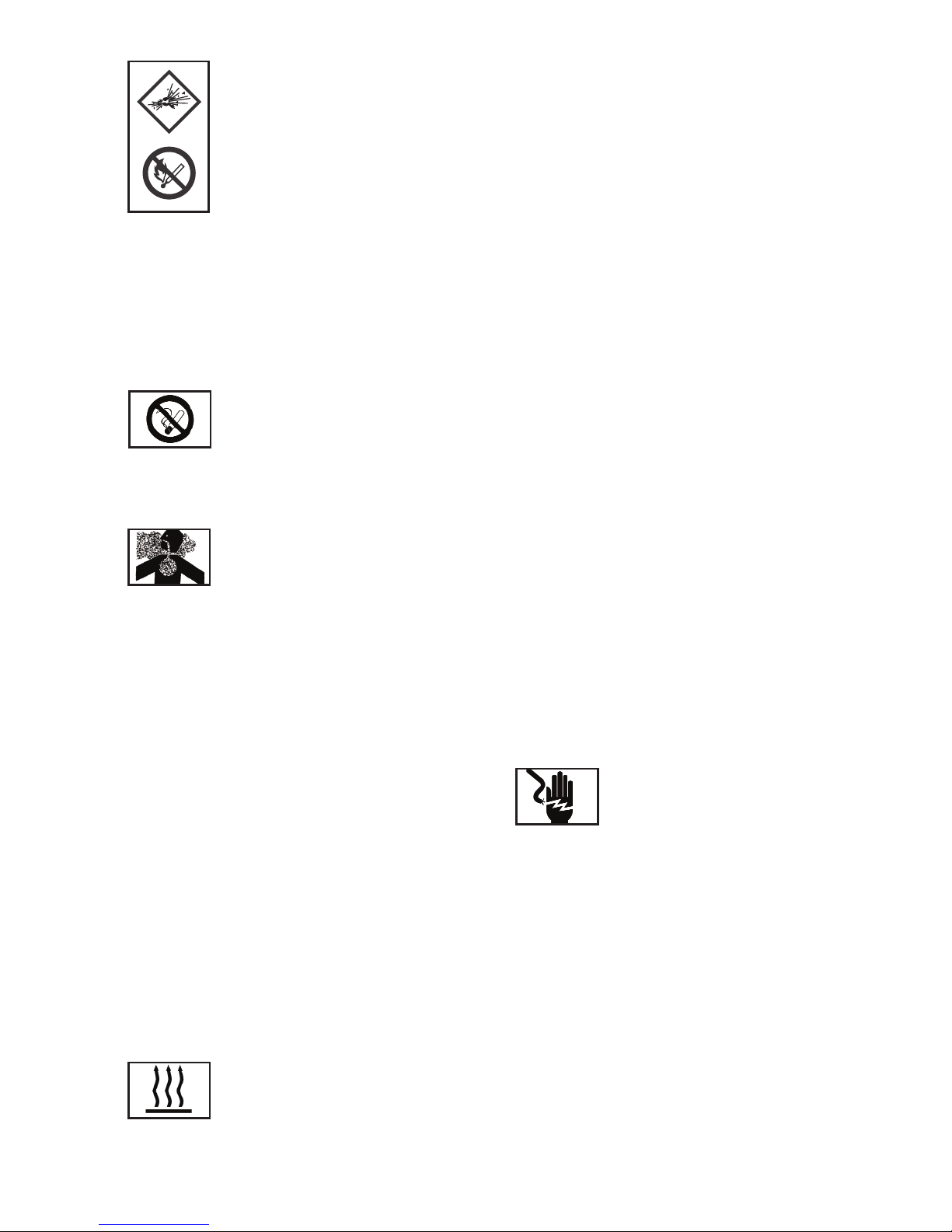
Risque d'explosion et d'incendie.
●La cartouche de combustible se présente
sous forme d'aérosol contenant des
produits inflammables. Il s'agit d'un récipient
sous pression et le gaz de propulsion restera
dans la cartouche. Tout manquement au
suivi des consignes de sécurité pourrait
entraîner une explosion ou un incendie.
Garder l'outil, les cartouches et la batterie à l'abri de la lumière
du soleil et à des températures n'excédant pas 50°C (120°F).
La cartouche de combustible/ou batterie pourrait exploser
en libérant des gaz inflammables. Ne pas perforer ou brûler
le récipient, même après utilisation. Ne pas incinérer,
recharger, récupérer ou recycler la cartouche de
combustible. Ne pas pulvériser sur une flamme ou sur aucun
autre matériau incandescent.
Tenir loin des sources d'étincelles – ne pas
fumer. Garder hors de la portée des enfants.
● Assurez-vous de lire et de suivre les consignes concernant
les « équipements de protection supplémentaires »
figurant ci-dessus.
A n'utiliser qu'à l'extérieur ou dans des
endroits bien ventilés.
Cet outil libère du monoxyde de carbone
dont l'inhalation est dangereuse pour la santé. Cet outil ne
doit pas être utilisé dans des endroits fermés ou mal ventilés.
Ne pas inhaler.
● Vérifier l'état du bras de contact avant toute utilisation. La
chambre et le bras de contact fonctionnent ensemble pour
faire fonctionner ce dispositif. Avant d'utiliser l'outil,
s'assurer que le bras de contact fonctionne correctement.
Sans clous, cartouche de combustible et batterie dans
l'outil, vérifiez ce qui suit : tirer le système de verrouillage de
l'alimentation du magasin vers l'arrière afin de désengager
le mécanisme de sécurité et, en prenant soin que l'outil soit
pointé vers le haut, appuyez sur le bras de contact et
assurez-vous qu'il retourne bien et en toute sécurité à sa
position originale. Si le bras de contact ne fonctionne pas
normalement, ne pas utiliser l'outil tant qu'il n'aura pas été
inspecté et réparé. A basse température, le bras de
contact fonctionne de façon particulièrement lourde et les
opérations d'enfoncement pourraient ne pas fonctionner.
Lorsque vous tirez le bouton du distributeur vers l'arrière, le
bras de contact doit bouger sans problème. Qui plus est, le
bras de contact ne doit jamais être modifié ou retiré de
l'appareil.
Ne pas toucher la zone située autour de
tube d'échappement.
Cet outil produit des gaz
d'échappement chauds qui pourraient enflammer les
matériaux inflammables.
● Le bras de contact et le nez deviendront chauds pendant
l'utilisation et de plus en plus chauds après une utilisation
prolongée ou rapide. Ne pas toucher à mains nues
● Retirer la batterie et la cartouche de combustible et tout
clou restant dans le magasin après utilisation.
● Retirer la batterie et la cartouche de combustible de l'outil
avant d'eectuer son entretien, avant de retirer un clou
coincé, avant de quitter la pièce de travail, avant de
transporter l'outil dans un autre endroit, ou après utilisation.
Il est très dangereux de déclencher un tir de clou par
inadvertance.
● L'environnement d'utilisation de cet appareil se situe entre
0°C (32°F) et 40°C (104°F). Il faut par conséquent s'assurer
qu'il ne soit pas utilisé en dehors de ces températures.
L'outil pourrait ne pas fonctionner par des températures en
dessous de 0°C (32°F) ou au-dessus de 40°C (104°F).
● Toujours charger la batterie à une température ambiante
située entre 0 et 40°C.
● En dessous de 0°C, la batterie pourrait être surchargée, ce
qui est dangereux. La batterie ne peut pas se recharger à
des températures supérieures à 40°C. La température
optimale de rechargement se situe entre 20 et 25°C.
● Ne pas utiliser le chargeur en continu. Lorsqu'un
rechargement est complet, laisser le chargeur pendant
environ 15 minutes avant de commencer le chargement
suivant.
● Prendre garde à ce qu'aucune substance ne se dépose
dans l'endroit ou s'insère la batterie rechargeable.
● Ne jamais démonter la batterie rechargeable ou le
chargeur.
Ne jamais court-circuiter la batterie
rechargeable.
Court-circuiter la batterie entraînerait la
libération d'un fort courant électrique et la batterie
surchauerait. La batterie pourrait en conséquence brûler
ou s'abîmer.
● Ne pas brûler la batterie usagée. Si la batterie brûle, elle
peut exploser.
● L'utilisation d'une batterie vide endommagera le chargeur.
● Dès que la batterie ne tient plus la
charge assez longtemps pour être utilisable, elle doit être
recyclée conformément à la législation en vigueur
localement.
● Ne pas insérer d'objets dans les fentes de ventilation du
chargeur. Insérer du métal ou des objets inflammables
dans les fentes de ventilation du chargeur causera un
danger d'électrocution ou endommagera le chargeur.
●
●
●
●
Page 24

Ne pas inhaler le contenu.
En cas d’inhalation, la personne aectée
doit être transportée en plein air et installée
dans une position confortable.
● L'expansion des gaz entraîne des températures basses.
Les gaz fluides pourraient être à l'origine de blessures
lorsqu'ils sont en contact avec la peau ou les yeux. En cas
de contact cutané, laver la surface en contact
soigneusement avec de l'eau tiède et du savon et
appliquer une crème une fois la zone sèche. En cas de
contact oculaire, rincer les yeux à l'eau courante.
Contacter un médecin si nécessaire.
● Stocker les cartouches de combustible dans un endroit
bien ventilé. Ne pas les stocker à des températures
excédant 50°C (120°F) (par exemple en contact direct avec
la lumière du soleil ou dans un véhicule). Ne pas exposer à
des flammes ou des étincelles. Ne pas perforer ou ouvrir la
cartouche de combustible. Ne pas recharger, récupérer
ou recycler la cartouche de combustible. Disposer de
l'aérosol conformément aux régulations locales en la
matière. Ne pas jeter la cartouche de combustible avec
d'autres déchets recyclables. Garder hors de la portée des
enfants.
TRANSPORT
● Il est interdit d'expédier des cartouches par la poste
● Le transport de petites quantités est permis pour usage
personnel dans un véhicule privé sans documents de
transport et carte d'urgence.
● Respecter la limite de température de 50°C (120°F).
STOCKAGE
● Ne pas stocker dans des endroits de passage, des halls
d'entrée ou de sortie, à proximité de portes ou dans un
grenier.
● S'assurer que l'outil, les cartouches de gaz et le chargeur
soient stockés conformément aux règles locales de
prévention de l'incendie.
● Respecter les régulations locales en matière de stockage,
de manipulation et de transport des produits en aérosols et
conformément à la norme TRG300(D). Les régulations
internationales sont établies conformément aux normes
ADR/RID; IATA-DGR; et au code IMDG
● Transport et stockage des cartouches de combustible.
Selon les normes GGVS-ADR, aucune licence particulière
n'est requise pour le transport de cartouches de
combustible. Par la route/par le train : Voir GGVS-ADR/RID
CI.2/ITEM 10B2
Par voie maritime : Voir IMDG CI.9/P.9022/EmS No. 2-13
Par voie aérienne/IATA-DGR : voir CI.2/Risk Gr.3/Packinstr.
203 /
Poids maximum par envoi : 75kg / par cargo : 150 kg NB :
Les marchandises doivent être accompagnées d'une carte
d'urgence pour le transport (numéro ONU 1950, (urgence
CI.2 GGVS/ADR, Rn.. numéro 2201, point IB02). Le transport
de petites quantités est permis pour usage personnel dans
un véhicule privé sans documents de transport et carte
d'urgence.
● Les kiosques de vente ne doivent pas se trouver à
proximité des sorties.
● Un extincteur de 6 kg, classe A, B, ou C doit être disponible.
● Les paquets doivent être empilés de manière sécuritaire
afin qu'ils ne tombent pas au sol.
● La surface des salles de stockage ne doit pas excéder 20
m2.
● Ne pas stocker avec des produits pyrotechniques.
● La quantité stockée dans les salles ne doit pas excéder
celle correspondant aux ventes quotidiennes.
● Les outils munis d'une flamme ou produisant une
température élevée ne doivent pas être utilisés à proximité
des cartouches de combustible.
● Les cartouches de combustible ne doivent pas être
placées dans les vitrines.
CHARGEMENT DE LA BATTERIE
Avant d'utiliser l'outil, charger la batterie en suivant les
consignes suivantes :
1. Insérer la batterie dans le chargeur :
Insérer la batterie fermement dans l'arrière du magasin,
en s'assurant qu'elle soit insérée dans le bon sens. Ne
pas forcer - vérifier la rotation (Fig. 2).
ATTENTION :
Les chargeurs 9B12073R-E sont conçus pour ces
batteries et ne doivent pas être utilisés pour charger
d'autres types de batteries. Il se peut que certaines
autres batteries s'insèrent dans le chargeur et
déclenchent l'allumage du voyant lumineux de
chargement en cours.
Ceci pourrait toutefois occasionner des dommages à la
fois au chargeur et à la batterie.
2. Brancher le cordon d'alimentation au secteur. Le
chargeur s'allumera automatiquement lorsque le cordon
d'alimentation sera branché au secteur (le voyant
lumineux s'allumera).
ATTENTION :
Si le voyant du chargeur ne s'allume pas, le débrancher
du secteur et vérifier que la batterie est correctement
●
Page 25
insérée dans le chargeur.
Il faut environ 60 minutes pour charger la batterie
complètement à une température d'environ 20°C. Le
voyant du chargeur s'éteindra automatiquement lorsque
la batterie sera chargée.
Le temps de chargement de la batterie peut s'allonger
par des températures plus basses ou si le voltage de
l'alimentation secteur est trop bas.
Si le voyant lumineux du chargeur ne s'éteint pas après
plus de 120 minutes, arrêter le chargement et contacter
le CENTRE DE REPARATIONS AGREE BOSTITCH.
ATTENTION :
Si la batterie est chauée, par exemple suite à une
exposition directe au soleil, juste après avoir été utilisée,
le voyant du chargeur pourrait ne pas s'allumer. Dans ce
cas, laisser la batterie se refroidir avant de la recharger.
Délai de rechargement : Le tableau 1 donne les temps
de rechargement nécessaires selon le type de batterie.
Tableau 1 : Temps de rechargement (approx. mins) à
20°C
NB : Le temps de rechargement pourra varier en
fonction de la température ambiante.
3. Débrancher le cordon d'alimentation du secteur.
4. Tenir le chargeur fermement et tirer sur la batterie.
NB : Après avoir chargé la batterie, retirez-la du
chargeur et rangez-la correctement. Ne pas ranger la
batterie dans le chargeur.
MODE ECONOMIE D'ENERGIE
Si l'appareil n'a pas été utilisé pendant environ une
heure et que la batterie est dedans, il passera
automatiquement en mode économie d'énergie afin de
minimiser la consommation d'énergie de la batterie. Le
mode économie d'énergie se met également en marche
lorsque la batterie manque sérieusement d'énergie ou
lorsque la machine est défectueuse. Veuillez par
conséquent faire attention au voyant lumineux de la
batterie lorsque vous réutilisez l'outil. Il sut pour cela
de retirer la batterie et de l'insérer de nouveau dans
l'outil).
2. Insérez la cartouche de combustible dans l'outil
i. Tirer sur le système de fermeture et ouvrir le couvercle
de la cartouche (Fig. 6).
ii. Insérer la cartouche de combustible dans l'outil (Fig. 7)
iii. Insérer le tube de la cartouche de combustible dans
l'ouverture de l'adaptateur (Fig. 8).
iv. Fermer le couvercle de la cartouche.
3. Charger les clous (voir partie 5 ci-dessous)
AVANT D'UTILISER L'OUTIL
Assurez-vous d'avoir lu et compris toutes les mises en garde
figurant dans ce manuel avant de vous mettre à utiliser l'outil
● Lorsque vous insérez une batterie ou une cartouche dans
l'outil, la zone de tir de l'outil doit être dirigée loin de
l'utilisateur ou d'autres personnes se trouvant dans la zone
de travail. Placez la zone de tir de l'outil sur une pièce test
de matériau ayant une épaisseur susante pour pouvoir y
enfoncer un clou. En prenant soin que vos mains ne
touchent pas la gâchette ou à la gâchette de sécurité et
que la zone de tir de l'outil soit dirigée loin de vous, vous
pouvez insérer la cartouche ou la batterie.
● Ne pas appuyer sur la gâchette ou sur la gâchette de
sécurité lorsque vous insérez la cartouche ou la batterie.
L'outil pourrait se mettre en marche et entraîner des
blessures.
CONSIGNES DE SECURITE POUR CHARGER L'OUTIL
Lorsque vous chargez l’outil :
1. Ne jamais diriger la zone de tir de l'outil vers les mains ou aucune
autre partie du corps ;
2. Ne jamais diriger l'outil vers soi-même ou vers autrui.
3. Ne pas appuyer sur la gâchette ou sur la gâchette de sécurité
car l'outil pourrait accidentellement se mettre en marche et causer
des blessures.
NB : Pour les consignes spécifiques de chargement et les
dimensions des attaches qu'il est conseillé d'utiliser, voir les
caractéristiques techniques de l'outil sur le devant de ce manuel.
CONSIGNES DE SECURITE POUR UTILISATION DE L'OUTIL
Toujours manipuler l'outil avec soin :
● Ne jamais chahuter avec ;
● Ne jamais appuyer sur la gâchette à moins que le nez de
l'appareil ne soit dirigé vers la pièce de travail.
● Assurez-vous que les autres soient à l'écart pendant que
vous utilisez l'outil car un déclenchement accidentel
pourrait se produire et causer des blessures.
● L'utilisateur ne doit pas garder le doigt sur la gâchette de
sécurité des outils en dehors des moments où l'outil est
eectivement utilisé car de sérieuses blessures pourraient
se produire suite à un déclenchement accidentel en cas
de contact de la gâchette avec quelqu'un ou quelque
chose.
Batterie Capacité de la batterie (Ah)
voltage (V) 1.4 Ah
7.2V 9B12072R-EU 60 mins.
Page 26

● Garder la zone de tir de l'outil loin des mains et autres
parties du corps. Un outil muni d'une gâchette de sécurité
peut rebondir suite au recul qu'entraîne l'enfoncement
d'un clou et un second clou peut accidentellement être tiré,
causant potentiellement des blessures.
● Vérifier fréquemment le bon fonctionnement de la gâchette
de sécurité. Ne pas utiliser l'outil si le bras de contact ne
fonctionne pas correctement car l'outil pourrait
accidentellement déclencher l'enfoncement de clous. Ne
pas interférer avec le bon fonctionnement du mécanisme
de sécurité de l'outil.
● Ne pas enfoncer de clous sur d'autres clous car cela
pourrait causer une déflection susceptible d'entraîner des
blessures.
● Ne pas enfoncer des clous près du bord de la pièce de
travail car le bois pourrait se fendre et permettre au clou de
passer au travers, causant un risque de blessure.
CONSIGNES DE SECURITE POUR
L'ENTRETIEN DE L'OUTIL
Lorsque vous travaillez avec des outils à gaz, faites attention aux
mises en garde figurant dans ce manuel et à l'outil lui-même.
Soyez très vigilants si vous évaluez des problèmes de
fonctionnement.
Afin de prévenir tout déclenchement accidentel et blessure
potentielle, retirez toujours la batterie ou la cartouche de
combustible ;
1. Avant de procéder à des réglages.
2. Lorsque vous entretenez l’outil :
3. Lorsque vous retirez un clou coincé.
4. Lorsque l'outil n'est pas utilisé.
5. Lorsque vous vous déplacez avec l'outil car ce dernier pourrait
se mettre en marche accidentellement et causer des blessures.
Vérifiez que l'outil fonctionne correctement en appuyant le nez sur
une chute de bois et en appuyant sur la gâchette une ou deux fois.
UTILISATION DE L'OUTIL
PREPARATION AVANT UTILISATION
Ne pas stocker l'outil, la batterie ou la cartouche de combustible
dans un endroit froid. Garder l'outil, la batterie et la cartouche de
combustible dans un endroit tempéré jusqu'à ce que vous vous en
serviez.
● Si l'outil, la batterie ou la cartouche de combustible sont
déjà froids, mettez-les dans un endroit chaud afin de les
réchauer avant de vous en servir.
● Respecter la limite de température de 50°C (120°F).
● Ne pas exposer à des flammes ou des étincelles.
● Cet outil pourrait ne pas enfoncer les clous complètement
lorsque - à basse température, la cartouche de
combustible perd de sa puissance de propulsion, - à
température élevée, la performance de l'outil peut être
aectée.
● Ne pas utiliser l'outil sous la pluie ou dans des conditions
particulièrement humides.
● Il est déconseillé d'utiliser cet outil à plus de 1500 m
d'altitude (5000 pieds) ou à des températures en dessous
de 0°C (30°F).
1. CARTOUCHE DE COMBUSTIBLE
Pour attacher la valve de niveau à une cartouche de combustible
1. Séparer la valve de niveau et le couvercle de la cartouche de gaz
(Fig. 3a).
2. Appuyer vers l'avant (côté souche) puis vers le bas sur la face
avant de la valve de niveau (Fig. 3b).
3. Appuyer vers le bas à l'arrière de la valve de niveau jusqu'à ce
qu'elle soit enclenchée étanchement (Fig. 3c).
Pour vérifier que la valve de niveau est correctement installée :
Appuyer deux ou trois fois la souche de la valve placée sur la
cartouche de combustible contre un objet immobile et relâchezla. Si le gaz n'est pas libéré, la cartouche de combustible est vide
et doit être remplacée.
OBSERVEZ LES CONSIGNES DE SECURITE
ATTENTION: Si la valve de niveau laisse échapper du gaz, ou si la
cartouche de gaz attachée à la valve de niveau fuit, remplacez
cette dernière.
N'essayez pas de réutiliser la valve de niveau - remplacez-la avec
chaque cartouche.
2. BATTERIE
Vous devez charger la batterie avant chaque utilisation - voir
section précédente "CHARGEMENT DE LA BATTERIE".
3. CONTROLE DE SECURITE
● L’équipement doit être tenu hors de la portée des
personnes non autorisées à l'utiliser (y compris les
enfants).
● Porter des lunettes.
● Vérifier que les vis qui tiennent le couvercle supérieur en
place soient bien serrées. Vérifier que l'outil ne comporte
pas de pièces défectueuses ou rouillées.
● Vérifier que le bras de contact fonctionne correctement sans
clous, cartouche de combustible et batterie dans l'outil.
Vérifier également si de la saleté est collée aux éléments
Page 27

mobiles du bras de contact.
● Assurez-vous que vous avez lu et compris toutes les
consignes de sécurité pertinentes de ce manuel avant de
vous servir de l'outil.
4. UTILISATION DE L'OUTIL : AVANT UTILISATION
1. Insérer la batterie dans la poignée de l'outil (Fig. 4)
NB : Ne pas faire fonctionner le bras de contact ou la gâchette
lorsque vous insérez la batterie.
-Assurez-vous que la lumière du voyant soit VERTE et qu'elle
clignote (Fig. 5).
-Si le voyant de la batterie clignote en ROUGE, la batterie n'a pas
assez de puissance et doit être rechargée.
VOYANT INDICATEUR DE LA BATTERIE
● Voyant clignotant VERT : La batterie possède encore assez
de puissance (le voyant cesse de clignoter pendant que
l'outil est utilisé).
● Voyant clignotant ROUGE : La batterie n'est pas
susamment chargée
● OFF (Pas de voyant allumé) : La batterie est à plat. Chargez
la batterie.
2. Insérer la cartouche de combustible dans l'outil
i. Tirer sur le verrou et ouvrir le couvercle de la
cartouche de combustible (Fig. 6).
ii. Insérer la cartouche de combustible dans l'outil (Fig.
7), en s'assurant que la souche de la cartouche soit
correctement alignée avec l'ouverture de l'adaptateur
(Fig. 8).
iii. Fermer le couvercle (Fig. 9).
5. CHARGEMENT DE L’OUTIL
ATTENTION : Lorsque vous chargez les clous dans
l’outil:●Ne pas appuyer sur la gâchette
●Ne pas appuyer sur le bras de contact
● Tenir le nez de l'appareil à l'écart de votre visage ou
de tout autre partie du corps et d'autrui afin d'éviter
d'éventuelles blessures lors du chargement de
l'outil.
1. Insérer une bande de clous dans l'arrière du magasin
(Fig. 9).
2. Faites glisser la bande de clou vers l'avant dans le
magasin (Fig. 10).
3. Tirer le distributeur de clous vers l'arrière (B) afin
d'enclencher le bouton du distributeur dans la bande de
clous (Fig. 11).
NB : Utiliser des bandes de plus de 10 clous.
Retirer les clous :
1. Tirer le bouton du distributeur vers l'arrière (Fig. 12).
2. Repousser le bouton du distributeur vers l'avant
doucement poussant le distributeur (B).
3. Retirer les clous par l'arrière du magasin (Fig. 13).
ATTENTION: Afin de prévenir tout déclenchement involontaire, ne
jamais toucher la gâchette ou placer la partie supérieure du bras
de contact sur un établi ou par terre. Ne jamais diriger la zone de
tir de l'appareil vers quiconque.
CHOIX DES CLOUS : GCN40T-E
AFIN D'ASSURER UNE FIXATION OPTIMALE SI VOUS
CLOUEZ DU BOIS À DU BÉTON OU UNE FINE FEUILLE
DE MÉTAL À DU BÉTON, VEUILLEZ UTILISER DES
ATTACHES DONT LES LONGUEURS CORRESPONDENT
AUX INDICATIONS CI-DESSOUS :
BOIS SUR BÉTON : CHOISISSEZ DES CLOUS DONT LA
PROFONDEUR D'ENFONCEMENT DANS LE BÉTON EST
DE 15-20MM
FINE FEUILLE DE MÉTAL SUR BÉTON : CHOISISSEZ DES
CLOUS DONT LA PROFONDEUR D'ENFONCEMENT
DANS LE BÉTON EST DE 12-20MM
6. UTILISATION DU CLOUEUR
ATTENTION :
● Pincer le bras de contact lorsque vous enfoncez un clou,
sinon le piston de reprendra pas correctement sa position
initiale.
● Vous remarquerez la présence d'huile autour du nez ou de
la sortie d'échappement si vous utilisez l'outil pendant des
périodes prolongées ; cela pourrait entraîner un eet de
mouchetage.
● Pour vous assurez que le matériau que vous clouez ne soit
pas marqué, essuyez tout excès d'huile qui apparaît sur
l'outil.
Épaisseur Longueur Profondeur
du bois de clou d'enfoncement
Appropriée dans du béton
10mm 30mm Environ 20mm
15mm 35mm Environ 20mm
20mm 40mm Environ 20mm
Page 28

CADENCE DE FONCTIONNEMENT
Ces outils sont conçus pour fonctionner selon les cadences de
fonctionnement suivantes :
Utilisation intermittente – 2 à 3 clous par seconde
Utilisation en continu – 1000 clous par heure
Excéder ces cadences pourrait entraîner une surchaue de l'outil,
ce qui pourrait faire baisser la performance ou abîmer les
composants de l'outil. En utilisant le cloueur selon sa cadence de
fonctionnement conseillée, vous pourrez enfoncer plusieurs
milliers de clous pendant une journée de travail normale.
GACHETTE DE SECURITE
Ces outils sont fournis munis d'une gâchette de sécurité
séquentielle et sont marqués d'un triangle équilatéral la pointe en
bas (▼●). N'essayez pas d'utiliser un outil portant ce signe si la
gâchette de sécurité est manquante ou semble être abîmée.
Le tir séquentiel nécessite que l'utilisateur tienne l'outil contre la
pièce à travailler en appuyant sur la gâchette de sécurité avant
d'appuyer sur la gâchette. Afin d'enfoncer des clous
supplémentaires, la gâchette doit être relâchée et l'outil soulevé de
la surface à travailler, avant de répéter l'action.
Cela permet de placer précisément et plus facilement les clous,
par exemple sur des encadrements ou des caisses ou pour
permettre un clouage en biais. Le tir séquentiel permet de
positionner les clous de façon très précise en évitant le
déclenchement accidentel de l'outil et le tir d'un second clou au
moment du recul de l'appareil. L'outil muni d'une gâchette de
sécurité séquentielle possède un avantage de sécurité parce qu'il
ne déclenchera pas accidentellement l'enfoncement d'un clou si
l'outil est en contact avec la surface de travail ou quoi que cela soit
d'autre, pendant que l'utilisateur appuie sur la gâchette.
VERROUILLAGE DE L'APPAREIL (GF33PT / GF28WW)
Ces outils utilisent un mécanisme permettant de prévenir le
déclenchement à vide de l'appareil.
Lorsque le magasin n'est pas chargé de clous ou lorsque le
nombre de clous présent dans le magasin est inférieur à 20, le bras
de contact ne peut pas fonctionner et l'outil ne se déclenchera
pas.
UTILISATION DE L'OUTIL :
UTILISATION EN TIR SÉQUENTIEL
A) Sans toucher la gâchette, appuyer le bras de contact contre la
surface de travail.
L'OUTIL NE DOIT PAS SE DECLENCHER.
B) Tenir l'outil au-dessus de la surface de travail et, en évitant de
pointer l'appareil vers soi ou vers autrui, appuyer sur la gâchette.
L'OUTIL NE DOIT PAS SE DECLENCHER.
C) En gardant l'outil au-dessus de la surface de travail, appuyer
sur la gâchette. Appuyer la gâchette de sécurité contre la surface
de travail
L'OUTIL NE DOIT PAS SE DECLENCHER.
A) Sans toucher la gâchette, appuyer la gâchette de sécurité
contre la surface de travail et appuyer sur la gâchette.
L'OUTIL DOIT SE DECLENCHER.
UTILISATION DE L'OUTIL
Après avoir vérifié que l'outil est en bon état de marche,
appuyer le nez contre la surface de travail et appuyer sur
la gâchette. Vérifiez que l'appareil ait bien enfoncé les
clous comme voulu (Fig. 14).
AJUSTER LA PROFONDEUR
D'ENFONCEMENT DES CLOUS
Afin de vous assurer que chaque clou soit enfoncé à la
même profondeur, faites en sorte que l'appareil soit
toujours fermement appuyé contre la surface de travail.
Si les clous sont enfoncés trop ou pas assez
profondément, vous pouvez ajuster la profondeur
d'enfoncement comme suit :
1. Retirer la cartouche de combustible et la batterie de
l'outil (Fig. 15).
2. Si les clous sont enfoncés trop profondément, changez
la position du bras de contact vers l'avant (Fig. 16). Si les
clous ne sont pas enfoncés assez profondément, changez
la position du bras de contact vers l'arrière (Fig. 17).
3. Arrêtez de bouger le bras de contact dès que vous
atteignez la position requise pour faire un test
d'enfoncement.
4. Remettre la cartouche de combustible et la batterie dans
l'outil.
PORTEZ TOUJOURS DES LUNETTES DE PROTECTION
Eectuer un test de clouage.
5. Retirer la cartouche de combustible et la batterie de
l'outil.
6. Continuer à régler l'appareil jusqu'à ce que la
profondeur d'enfoncement soit correcte, en procédant à
un test après chaque réglage.
7. CROCHET D'ACCROCHAGE (GF28WW / GF33PT)
Ces outils sont munis d'un crochet d'accrochage installé
sur le magasin et qui peut se replier pour ne pas entraver
l'utilisation de l'appareil. Pour ajuster le crochet, il sut
de le tourner dans la position voulue.
8. UTILISER L'EMBOUT ANTI-MARQUES (GNC40T)
Si vous avez besoin de protéger la surface de travail contre les
rayures ou marques faites par le bras de contact, vous pouvez
utiliser l'embout anti-marques fourni avec l'outil.
Page 29

1. Retirer d'abord la cartouche de combustible et la batterie de
l'outil.
2. Placer l'embout anti-marques comme indiqué sur les Fig. 18 en
fonction du modèle de votre outil.
3. L'embout est marqué afin d'indiquer le point de sortie du clou tiré,
rendant l'alignement encore plus facile.
Pour retirer l'embout, tirer dessus en suivant les étapes
d'installation à l'envers. Lorsque vous ne l'utilisez pas, attachez-le
à la zone de rangement située à l'arrière du magasin ou rangez-le
dans la mallette (Fig. 19).
ENTRETIEN & RECHERCHE DE PANNE
Retirer la cartouche de combustible et la batterie de l'outil et vider
complètement le magasin avant de commencer les opérations
d'entretien ou de réparation. Assurez-vous de lire et de
comprendre les mises en garde figurant dans ce manuel, dans
les données techniques de l'outil et sur l'outil lui-même et soyez
très vigilants lorsque vous évaluez le mauvais fonctionnement des
outils.
Les pièces détachées Bostitch sont à conseiller. Ne pas utiliser
de pièces modifiées ou de pièces qui ne fournissent pas une
performance égale à la performance de l'équipement d'origine.
ATTENTION : Assurez-vous de bien retirer la batterie et la
cartouche de combustible avant de retirer des clous coincés,
d'inspecter l'outil, de procéder à son entretien ou à son nettoyage.
RETIRER LES CLOUS COINCES
Si les clous sont coincés dans la tête de clouage, vous
pouvez ajuster l'appareil comme suit : GF28WW / GF33PT
1. Retirer la cartouche de combustible et la batterie de
l'outil.
2. Verrouiller de nouveau la butée dans le magasin et
retirer les attaches.
3. GF28WW / GFD33PT: Retirer les boulons à l'aide d'une
clef. (Fig. 20)
3. GNC 40T: Ouvrir le magasin. (Fig. 21)
4. Tirer le magasin à l'écart de la tête de clouage et
retirer les clous coincés. (Fig. 22 & 23)
5. Remettre la cartouche de combustible et la batterie
dans l'outil.
INSPECTION DU MAGASIN
1. Retirer d'abord la cartouche de combustible et la batterie de
l'outil.
2. Nettoyer le magasin. Retirer les morceaux de papier ou copeaux
de bois qui pourraient s'être accumulés dans le magasin. Lubrifier
le magasin avec le lubrifiant pour cloueur de finition à gaz Bostitch
(Fig. 24).
VERIFICATION DES VIS DE MONTAGE
Vérifier fréquemment que les vis de montage de chaque élément
du cloueur soient bien serrées et resserrer celles qui ne le sont
pas. Il peut s'avérer dangereux d'utiliser l'outil si certaines vis ne
sont pas bien serrées.
INSPECTION DU BRAS DE CONTACT
Vérifier que le bras de contact glisse facilement. Nettoyer la zone
de glissement du bras de contact et utiliser l'huile fournie pour le
lubrifier de temps en temps. Ceci permettra une utilisation sans
encombre et aidera à prévenir la formation de rouille.
PREPARATION DE L'OUTIL POUR LE RANGER
● Lorsque l'outil n'est pas utilisé pendant longtemps,
appliquer une fine couche de lubrifiant sur les parties en
acier afin de prévenir l'apparition de rouille.
● Ne pas ranger le cloueur dans un environnement froid.
Lorsque vous n'utilisez pas le cloueur, l'outil doit être rangé
dans un endroit sec et tempéré.
● Garder hors de la portée des enfants.
● Veuillez vous référer à toutes les consignes fournies dans
la section précédente de ce manuel concernant le
Rangement de l'outil.
LISTE DES PIECES DETACHEES DE REPARATION
ATTENTION : L'inspection, la réparation et l'entretien des outils
électriques Stanley Bostitch ne doivent être eectués que par un
Centre agréé.
Il sera utile de présenter la liste des pièces détachées fournie avec
cet outil au Centre agréé Bostitch lorsqu'une réparation est
nécessaire ou lors de l'entretien de l'outil.
Lors de l'utilisation ou de l'entretien d'outils électriques, les
régulations et standards de chaque pays doivent être respectés
en matière de sécurité.
MODIFICATIONS
Les outils Stanley Bostitch font constamment l'objet
d'améliorations et de modifications afin d'y intégrer les dernières
avancées technologiques. Ainsi, certaines pièces peuvent être
changées sans préavis.
LUBRIFIANTS CONSEILLES
Utilisez les lubrifiants pour cloueur à gaz BOSTITCH.
Ne pas utiliser d'huile détergente ni d'additifs : ces lubrifiants
abîmeront les joints toriques et autres parties en caoutchouc et
entraîneront un fonctionnement erroné de l'appareil.
DONNEES CONCERNANT LE BRUIT ET LES VIBRATIONS
EMISSION DE BRUIT (Voir les données techniques de l'outil)
Les valeurs de bruit caractéristiques de l'outil ont été évaluées
Page 30

selon la norme EN 12549 - “Acoustique - Code d'essai
d'acoustique des cloueurs à gaz - Méthode d'ingénierie."
Ces valeurs sont des caractéristiques relatives aux outils et ne
correspondent pas au développement du bruit au point
d'utilisation. Le développement du bruit au point d'utilisation peut
par exemple dépendre de l'environnement de travail, de la pièce
à travailler, du support de la pièce en question et du nombre d'outils
utilisés, etc.
En fonction des conditions de travail sur le chantier et de la forme
de la pièce de travail, des mesures d'atténuation de bruit peuvent
s'avérer nécessaires au niveau individuel ; par exemple en plaçant
la pièce de travail sur un support atténuant le bruit, en calant les
pièces de travail afin d'empêcher les vibrations ou en les couvrant,
en ajustant la pression d'air minimum requise pour la tâche, etc.
INFORMATION CONCERNANT LES VIBRATIONS (Voir les
données techniques de l'outil)
Les valeurs caractéristiques de vibrations de l'outil ont été
déterminées selon la norme ISO/WD 8662-11 "Mesure des
vibrations chez les utilisateurs d'outils électriques portables - Partie
11 Outils de fixation".
Cette valeur correspond à la caractéristique relative de l'outil et
non pas à l'impact sur le système main-bras au moment de
l'utilisation. L'impact sur le système main-bras lors de l'utilisation
de l'outil dépendra par exemple de la force d'emprise, de la force
de contact, de la direction de travail, des réglages de l'alimentation
en air comprimé, de la pièce de travail par elle-même, de son
support etc.
INTERVALLES D'ENTRETIEN
Les intervalles d'entretien de l'outil dépendent de l'environnement
dans lequel il est utilisé, des applications pour lesquelles il est utilisé
et du volume de clous qu'il enfonce. Par exemple, si l'outil est utilisé
dans des conditions sales et poussiéreuses pour enfoncer de
grosses quantités de clous, l'entretien s'imposera plus
régulièrement que s'il est utilisé dans des conditions propres pour
des petites quantités de clous.
Le diagramme qui suit a été produit comme guide pour vous aider
à établir la fréquence d'entretien de vos outils. Si vous faites face
à une accumulation excessive de débris dans l'outil, entre les
nettoyages, augmentez la fréquence d'entretien de l'appareil. Si
l'outil n'a pas besoin d'être nettoyé dans les délais que vous avez
déterminés, la fréquence d'entretien peut alors être diminuée. Si
vous avez des questions concernant les conseils ci-dessus,
veuillez contacter votre distributeur local. Il sera à même de vous
aider et de vous conseiller.
Intervalles entre les entretiens
GF33PT-E / GF28WW-E / GCN40T-E
:
NETTOYAGE DU FILTRE
Pour qu'il soit plus facile de s'y référer, les références aux figures
citées correspondent aux instructions fournies dans la fiche
séparée (Nettoyage du filtre/Nettoyage de l'outil & Guide de
lubrification.
Lorsque vous nettoyez l'outil, faites attention à ne pas perdre
d'éléments une fois l'outil démonté et n'utilisez que des pièces
Stanley Bostitch afin de vous assurez d'un fonctionnement de
l'appareil correct et en toute sécurité.
1. Avant tout nettoyage, assurez-vous que l'outil ait refroidi
complètement et retirez tous les clous restant dans le magasin
ainsi la cartouche de combustible et la batterie. (Fig. 25)
2. En utilisant des clefs hex de 4mm, retirer et retenir le boulon
barillet à tête hex. (Fig. 26) (M5 x 14)
3. Repousser le couvercle supérieur vers l'arrière (Fig. 27)
4. Retirer le filtre de l'intérieur du couvercle supérieur (Fig. 28).
5. Retirer la poussière et les débris du filtre avec le nettoyant
Bostitch [SB-TC1]. S'assurer que le filtre soit sec et non
contaminé. Remettre le filtre et le couvercle du filtre en place (Fig.
29).
6. Reconnecter le fil conducteur de la bougie d'allumage et le fil
conducteur du moteur. (Fig. 30)
A) Vérifier que les fils conducteurs soient dans la rainure.
B) Vérifier que les fils conducteurs ne soient pas coincés par le
couvercle.
C) Vérifier la position de réglage du fil d'alimentation
7. S'assurer que le filtre ne soit pas endommagé. S'il est
endommagé, remplacer le filtre avec un filtre neuf (Pièce no.
192103) en s'assurant qu'aucun des fils d'alimentation ne soient
coincés (Fig. 31)
8. Remettre le couvercle supérieur en s'assurant de ne coincer
aucun fil (Fig. 32).
9. Remettre le boulon barillet (Fig. 33)
Nombre de jours entre
les entretiens
Très sale & poussiéreux 3 - 4 3 - 4 3 - 4 3 - 4 3 - 4
Poussiéreux 10-14 10-14 10-14 3-4 3-4
Modérément sale 30-45 30-45 30-45 10-14 10-14
Propre 45-60 45-60 45-60 30-45 30-45
12468+
Nombre de clous tirés par semaine [x1000]
Environnement
d'utilisation
Page 31

10. Toujours faire fonctionner l'outil 5 à 10 fois sur des chutes avant
de continuer la tâche sur la surface de travail afin de débarrasser
l'outil de tout résidu de produit de nettoyage [SB-TC1] (Fig. 34)
NETTOYAGE & LUBRIFICATION
Assurez-vous d'avoir bien lu et compris toutes les mises en garde
de sécurité et les procédures de nettoyage avant d'utiliser ou de
nettoyer cet outil. Tout manquement à lire et comprendre ces
mises en garde et procédures pourrait entraîner des blessures
graves.
Mise en garde : S'assurer que les 4 boulons à tête hex 4 soient
bien vissés à la tête du cylindre avant d'utiliser l'outil. Les boulons
manquants ou mal serrés pourraient être à l'origine de fuite de gaz
brûlant susceptible de blesser l'utilisateur et d'endommager l'outil
et l'endroit où il est utilisé.
1. Avant tout nettoyage, s'assurer que l'outil ait refroidi
complètement et retirer tous les clous restant dans le magasin
ainsi la cartouche de combustible et la batterie. (Fig. 35)
2. En utilisant des clefs hex de 4mm, retirez et retenir le boulon
barillet à tête hex. (Fig. 36) (M5 x 14)
3. Repoussez le couvercle supérieur vers l'arrière (Fig. 37)
4. Retirer le filtre de la tête du cylindre (Fig.. 38).
5. Débrancher la connexion de la bougie d'allumage de la bougie
(Fig. 39) et débrancher doucement le fil d'alimentation du moteur
(Fig. 40)
6. En utilisant des clefs hex de 4mm, retirer et retenir les 4
boulons barillets à tête hex. de la tête du cylindre. (Fig. 41) (M54
x 20, 4pcs)
7. Soulever doucement la tête du cylindre de la chambre de
combustion. (Fig. 42).
8. En s'assurant de ne pas endommager les pales du ventilateur,
retirer le joint torique du ventilateur. (Fig. 43)
9. En utilisant un chion sec, nettoyer et retirer toutes les saletés
situées au niveau du joint torique. Inspecter le joint torique pour
déterminer son état et le remplacer si nécessaire (pièce no.
192114). (Fig. 45)
10. Nettoyer la tête du cylindre en utilisant un produit nettoyant
pour freins et en faisant particulièrement attention à la bougie
d'allumage. (Fig. 46)
11. Une petite brosse pourrait s'avérer utile pour débarrasser
l'appareil de petits débris. Il faudra peut-être répéter l'opération
2 à 3 fois pour que l'appareil soit propre. (Fig. 47)
12. Remplacer le joint torique de la tête du cylindre. (Fig. 48)
13. Lubrifier le joint torique avec le Lubrifiant pour cloueur à gaz
Bostitch [Pièce No. SB-20CL]. (Fig. 49)
14. Pulvériser du produit nettoyant à freins dans le cylindre afin de
décrocher tout résidu (Fig. 50).
15. Avec un instrument allongé, (par ex. la poignée d'un tournevis),
pousser le piston vers le bas. (Fig. 51)
16. En tenant l'outil la tête en bas, pulvériser du produit nettoyant
à freins dans la chambre de combustion et dans la tête de la
chambre en s'assurant que tous les résidus tombent de l'appareil.
Il vous faudra peut-être répéter l'opération 2 à 3 fois en utilisant
éventuellement une petite brosse pour détacher certains résidus
diciles à faire sortir. (Fig. 52)
17. Avec un tournevis, ou un instrument similaire, repousser la
plaque d'enfoncement à l'intérieur de l'outil. (Fig. 53)
18. Tirer le distributeur de clous vers l'arrière afin de
désenclencher le mécanisme de verrouillage de l'appareil et
appuyez le bras de contact contre une surface dure. En utilisant
le Lubrifiant pour cloueur à gaz Bostitch (Pièce No. SB-20CL),
graisser autour de l'extérieur de la rainure dans la chambre de
combustion, là où se trouve le joint torique. (Fig. 54)
19. En s'assurant que le joint torique soit correctement placé sur
la tête du cylindre, remettre doucement la tête du cylindre au
sommet de l'outil, en prenant soin de ne pas endommager les
pales du ventilateur. (Fig. 55)
20. En relâchant le corps de l'appareil, remettre la tête du cylindre
en place et vérifier que le joint torique ne soit pas pincé. Remettez
les 4 boulons barillets. (Fig. 56)
21. Remettre les 4 boulons barillets dans leurs positions d'origine
en utilisant une clef hex de 4mm (mettre un des 4 boulons barillet
au travers la plaque des fils). Serrer les boulons barillet tout en
fixant bien le fil à la plaque des fils (Fig. 57 & 58)
22. Vérifier que le joint torique soit à la bonne place en tirant le
distributeur de clous vers l'arrière et en appuyant sur le bras de
contact. (Fig. 59)
23. Reconnecter le fil conducteur du moteur et de la bougie
d’allumage. (Fig.60 & 61)
24. Régler de nouveau le fil conducteur de la bougie d'allumage
et le fil conducteur du moteur. (Fig. 62)
A) Vérifier que les fils conducteurs soient dans la rainure.
B) Vérifier que les fils conducteurs ne soient pas coincés par le
couvercle.
C) Vérifier la position de réglage du fil d'alimentation
25. Remettre le filtre en s'assurant de ne coincer aucun fil. (Fig. 63)
26. Remettre le couvercle supérieur en s'assurant de ne coincer
aucun fil. (Fig. 64)
27. Remettre le boulon barillet. (Fig. 65)
28. Vérifier que le dessus des 4 boulons barillets ressortent bien
du corps de l'outil. (Fig. 66)
29. Toujours faire fonctionner l'outil 5 à 10 fois sur des chutes avant
de continuer la tâche sur la surface de travail afin de débarrasser
l'outil de tout résidu de produit de nettoyage. (Fig. 67)
Page 32

PROBLEME METHODE DE CONTROLE CORRECTION
Le cloueur fonctionne mais n'enfonce Vérifier qu'il n'y ait pas de clou coincé. Retirer le clou coincé..
pas de clous. Vérifier que le distributeur de clous fonctionne correctement. Nettoyer et lubrifiez si nécessaire.
Le ressort à ruban est-il moins ecace ou endommagé ? Remplacer le ressort à ruban.
Vérifier que vous utilisez les clous appropriés N'utiliser que les clous recommandés.
Il saute des clous. Vérifier que le piston de la plaque d'enfoncement Retirez la batterie, la cartouche de combustible et les clous de
L'alimentation en clous est intermittente. a bien repris sa position l'outil et, en utilisant une pièce de métal fine ou un tournevis,
de 100mm de long (non fourni), insérez le dans le bras de contact
(Fig. 58) et repoussez la barre vers la position la plus haute.
Vérifier que seuls les clous appropriés soient utilisés. N'utilisez que les clous recommandés.
Vérifier que le distributeur de clous fonctionne correctement Nettoyer et lubrifier.
Le ressort à ruban est-il moins ecace ou endommagé ? Remplacez le ressort à ruban.
Le distributeur de clous est-il usé ou abîmé ? Remplacer le distributeur de clous
Vérifier que les pistons retournent bien en position. Appuyer fermement sur la gâchette pendant environ 0,5 secondes
après combustion.
Vérifier que les pistons fonctionnent correctement. Si la température est trop basse, réchauer la cartouche de
combustible à moins de 50°C (120°F).
Clous coincés. Vérifiez que seuls les clous appropriés soient utilisés. N'utilisez que les clous recommandés.
Le clou enfoncé est tordu. La plaque d'enfoncement est-elle abîmée ? Contacter Bostitch pour la faire remplacer.
Le distributeur de clous est-il usé ou abîmé ? Remplacez le distributeur de clous
Le bras de contact ne fonctionne Le bras de contact est-il voilé ? Contactez Bostitch pour la faire remplacer.
Vérifier qu'il n'y a pas de débris sur la zone de mouvement du Contactez Bostitch pour la faire remplacer.
bras de contact.
Le ventilateur fonctionne, le voyant vert Vérifiez que les pistons retournent bien en position. Appuyer complètement sur le bras de contact.
s'allume mais le cloueur n'enfonce pas La température est trop basse ; réchauer la cartouche
les clous ou ne fonctionne pas de façon stable. en-dessous de 50°C (120°F)
Vérifiez la cartouche de combustible. Reste-t-il assez La remplacer avec une nouvelle cartouche.
de combustible ?
Vérifier le fil d'alimentation de la bougie d'allumage. Est-il abîmé ? Contactez Bostitch pour le faire remplacer.
Vérifier la bougie d'allumage. Est-elle encrassée ? Contacter Bostitch pour la faire remplacer.
Vérifier le filtre. Est-il encrassé ? Le nettoyer conformément au Tableau d'entretien
Le ventilateur de se met pas en route lorsque Le magasin est vide. Ajouter des clous dans le magasin.
le levier poussoir est appuyé. Remarquer la couleur du voyant. S'il est rouge, recharger la batterie.
S'il est vert : Contacter Bostitch pour la faire remplacer.
La batterie ne se recharge pas. Vérifier l'état du cordon d'alimentation.
ACTION POURQUOI COMMENT
Nettoyage du magasin et le du dispositif de distribution. Prévention les clous coincés. Aspiration quotidienne de la poussière.
Faire en sorte que le bras de contact Promouvoir la sécurité de l'utilisateur et Aspiration quotidienne de la poussière.
fonctionne correctement le bon fonctionnement du cloueur.
Tableau d'entretien
Recherche de pannes par l'utilisateur
Page 33

A Longueur en mm. K Capacité du magasin
B Hauteur en mm. L Température ambiante de travail
C Largeur en mm. M Réf. Chargeur
D Poids en Kg. N Entrée bloc d'alimentation
E Bruit LPA 1s d O Temps de chargement en minutes à 20ºc (70f)
F Bruit LWA 1 s d P Voltage de chargement
G Vibrations m/s2 Q Courant de chargement
H Nom de l'outil de fixation R Poids en Kg.
I(a) Dimensions mm. S Batterie (Kg)
I(a) Dimensions mm. T Type de batterie
J Tête/couronne U
Cartouche de combustible - Hydrocarbure liquide : propane/butane
Références du tableau de données techniques (Voir page 2)
Page 34

SICHERHEITS- UND BEDIENUNGSANLEITUNG
DIESES ELEKTROWERKZEUG WIRD DURCH
EINE INTERNE VERBRENNUNGSEINRICHTUNG
ANGETRIEBEN UND SOLLTE AUSSCHLIESSLICH
ZUSAMMEN MIT IN DIESER BEDIENUNGSANLEITUNG
EMPFOHLENEN VERTEILERN FÜR BRENNBARE GASE
BETRIEBEN WERDEN.
DER BEDIENER DIESES WERKZEUGS SOLLTE SICH EINGEHEND
MIT DIESER BEDIENUNGSANLEITUNG UND DEM
WERKZEUGTECHNISCHEN DATENHANDBUCH VERTRAUT
MACHEN UND STETS DIE SICHERHEITSHINWEISE UND
ANLEITUNGEN BEACHTEN. BEWAHREN SIE DIESE ANLEITUNG
ZUSAMMEN MIT DEM WERKZEUG ZUM SPÄTEREN
NACHSCHLAGEN AUF.
WENDEN SIE SICH BEI FRAGEN AN IHRE VERTRETUNG ODER
IHREN HÄNDLER FÜR BOSTITCH GERÄTE.
Bei der Entwicklung von Bostitch Werkzeugen wird größter Wert
auf eine ausgezeichnete Kundenzufriedenheit sowie auf eine
optimale Leistung im Einsatz mit Bostitch PräzisionsBefestigungselementen gelegt, welche nach denselben
Standards hergestellt werden. Beim sachgemäßen und
sorgsamen Umgang mit diesen Geräten wird eine eziente und
zuverlässige Leistung gewährleistet. Um die besten Ergebnisse
zu erzielen, sollten, wie für jedes hochwertige Elektrowerkzeug,
die Anleitungen des Herstellers beachtet werden.
Hinweis: Je nach Art der Anwendung des Werkzeugs sind
möglicherweise zusätzliche Sicherheitsmaßnahmen erforderlich.
Wenden Sie sich bei Fragen zum Werkzeug oder zur Bedienung
an Ihre Vertretung oder Ihren Händler für Bostitch Geräte.
Hinweis: Bostitch übernimmt keine Haftung für die Funktion eines
Werkzeugs, wenn ein Gerät zusammen mit
Befestigungselementen oder Zubehörteilen eingesetzt wird, die
die besonderen Anforderungen für an Original-Nägel,
Heftklammern, Batterien, Brennstozellen, Ladegeräte und
Zubehörteile von Bostitch erfüllen.
EINGESCHRÄNKTE GARANTIE
Bostitch GmbH gewährleistet dem Käufer von Originalgeräten
eine Garantie von 90 Tagen ab Kaufdatum auf Material und
Verarbeitung der Produkte und übernimmt nach Ermessen von
Bostitch die Reparatur oder den Austausch von defekten
Produkten. Diese Garantie ist nicht übertragbar. Diese Garantie
umfasst ausschließlich Material- und Verarbeitungsmängel.
Schäden oder Fehlfunktionen auf Grund von normalem
Verschleiß, unsachgemäßer oder missbräuchlicher Verwendung
oder von Unfällen sind von der Garantie ausgeschlossen.
DIESE GARANTIE IST AUSSCHLIESSLICH UND ERSETZT ALLE
ANDEREN AUSDRÜCKLICHEN GEWÄHRLEISTUNGSANSPRÜCHE.
EINE GARANTIE DER MARKTGÄNGIGKEIT UND DER EIGNUNG
FÜR EINEN BESTIMMTEN ZWECK BESCHRÄNKT SICH AUF
DIE DAUER DIESER GARANTIE. BOSTITCH ÜBERNIMMT KEINE
HAFTUNG FÜR ZUFÄLLIGE ODER FOLGESCHÄDEN.
In einigen Ländern ist die Einschränkung der gesetzlichen
Gewährleistungsfrist, der Ausschluss oder die Einschränkung von
zufälligen oder Folgeschäden untersagt, so dass die genannten
Einschränkungen in Ihrem Land unter Umständen nicht zutreen.
In dieser Garantie werden Ihnen bestimmte Rechte eingeräumt.
Je nach Staat oder Land werden Ihnen weitere Rechte gewährt.
Zur Inanspruchnahme der Garantie müssen Sie das Produkt
zusammen mit dem Kaufbeleg auf eigene Kosten an eine örtliche
Bostitch Garantiewerkstatt einsenden.
ZUBEHÖR
Folgendes Zubehör ist im Lieferumfang dieser Werkzeuge
enthalten:
1) Ladegerät x 1
2) Tragekoer x 1
3) Sechskantschlüssel für M5-Schrauben x 1
4) Öler x 1
5) Batterie x 2
Weiteres Zubehör separat erhältlich:
1) Brennstozellen Art.-Nr.:
FC80ML / FC80ML-HP
2) 250 ml Schmieröl für Haftennägel Art.-Nr.: SB-20CL
ALLGEMEINE SICHERHEITSHINWEISE
Mit diesem Werkzeug sollten ausschließlich in dieser
Bedienungsanleitung empfohlene Befestigungselemente,
Batterien, Brennstozellen und Ladegeräte verwendet werden.
Das Werkzeug und die empfohlenen Befestigungselemente
werden aus Sicherheitsgründen als ein gemeinsames
Werkzeugsystem angesehen.
Reparaturen sollten aus Sicherheitsgründen ausschließlich von
zugelassenen Bostitch Vertretungen oder von Fachpersonal
sowie gemäß den Bedienungs- und Wartungshinweisen in dieser
Anleitung und im werkzeugtechnischen Datenhandbuch
durchgeführt werden.
Hinweis: Facharbeiter sind Personen mit entsprechend
qualifizierter Ausbildung bzw. ausreichender Erfahrung im Bereich
Eintriebgeräte für Befestigungselemente, die über Kenntnisse zur
sicheren Bedienung von Eintriebgeräten für
Befestigungselemente verfügen.
DE
Page 35

BEACHTEN SIE ERGÄNZEND ZU DEN SICHERHEITSHINWEISEN
IN DIESER ANLEITUNG DIE FOLGENDEN HINWEISE ZUR
SICHEREN BEDIENUNG:
Elektrische Werkzeuge niemals zusammen mit dem Hausmüll
entsorgen!
Unter Einhaltung der Europäischen Richtlinie
2002/96/EC & 2006/66/EC über Elektro- und
Elektronik-Altgeräte/batterien und der
Anwendung unter Einhaltung staatlicher
Gesetze müssen elektrische/ batterien Werkzeuge nach
Ende der Lebensdauer an ein umweltfreundliches
Recyclingunternehmen zurückgeführt werden.
● Behandeln Sie Ihr Bostitch Gerät wie ein professionelles
Werkzeug. Das Gerät ist kein Spielzeug. Niemals mit dem
Gerät Unfug treiben.
● Das Bostitch Werkzeug sollte ausschließlich zum
angegebenen Zweck verwendet werden, z. B.: für
Rahmungen, Ständerwände, zum Unterbodenbau oder zur
Nagelung von Holz an Beton (nur GNC40T). Die
Werkzeugmodelle GF28WW/GF33PT sind ausschließlich zur
Verbindung von Holzmaterial vorgesehen.
● Einen Nagel niemals über einem anderen Nagel eintreiben.
● Einen Nagel niemals in Metall eintreiben.
● Das Werkzeug niemals in einer Weise einsetzen, dass ein
Befestigungselement in Richtung des Bedieners oder
anderer Personen in der Umgebung gelangen könnte.
● Das Werkzeug nicht als Hammer missbrauchen.
● Das Werkzeug stets am Gri transportieren. Das Werkzeug
niemals mit gezogenem Auslöser tragen.
● Der Originalzustand und die Funktion des Werkzeugs darf
nicht ohne schriftliche Genehmigung von Stanley Bostitch
verändert werden.
● Bei Missbrauch oder unsachgemäßem Einsatz dieses
Werkzeugs besteht Verletzungsgefahr für Sie und andere
Personen.
● Auslöser und Sicherheitsauslösung niemals in der
ausgelösten Position festklemmen oder mit Klebeband
arretieren.
● Das Werkzeug niemals mit eingesetzter Brennstozelle oder
Batterie unbeaufsichtigt lassen.
● Das Werkzeug nicht ohne lesbar angebrachtes
SICHERHEITSETIKETT verwenden.
● Ein fehlerhaft arbeitendes Werkzeug nicht weiter
verwenden. Wenden Sie sich bei wiederholten
Funktionsstörungen an die nächste Stanley Bostitch
Vertretung.
● Halten Sie das Werkzeug während der Arbeit so, dass
Verletzungen des Kopfes oder am Körper ausgeschlossen
werden können, falls sich der Rückstoß des Werkzeugs bei
variierendem Gasdruck oder bei harten Werkstücken erhöht.
● Das Werkzeug nicht zu nahe an den Ecken oder an den
Rändern eines Werkstücks verwenden. Das
Befestigungselement könnte aus dem Werkstück getrieben
werden und Verletzungen verursachen.
● Vor dem Transport des Werkzeugs Brennstozelle und
Batterie herausnehmen.
● Vor dem Einsatz die Funktion der Sicherheitsauslösung (falls
vorhanden) und des Auslösers überprüfen.
● Werkzeugteile zu keiner Zeit entfernen oder blockieren,
insbesondere die Sicherheitsauslösung.
● „Notfallreparaturen“ nicht ohne geeignete Werkzeuge
vornehmen.
● Keine Bohrungen oder Gravuren am Werkzeug vornehmen.
● Dieses Elektrowerkzeug wird durch eine interne
Verbrennungseinrichtung angetrieben. Das Elektrowerkzeug
sollte ausschließlich mit in dieser Bedienungsanleitung
empfohlenen Verteilern für brennbare Gase betrieben
werden.
● Das Werkzeug darf nicht von Kindern oder Personen bedient
werden, denen die korrekte Funktionsweise des Gerätes
nicht bekannt sind.
● Die Einzelteile des Gerätes stets unverändert lassen.
Abdeckungen oder Schrauben nicht entfernen. Lassen Sie
diese Teile unverändert und an ihrer ursprünglichen Position.
Zudem dürfen keine Änderungen am Werkzeug
vorgenommen und ein so verändertes Werkzeug nicht
verwendet werden.
● Das Werkzeug vor dem Einsatz überprüfen. Überprüfen Sie
vor dem Einsatz des Werkzeugs, dass alle Bauteile
unversehrt, sämtliche Schrauben festgezogen und keine
Teile fehlen oder korrodiert sind.
● Bei extrem beanspruchenden Arbeiten besteht Unfallgefahr.
Werkzeuge und Zubehör niemals überbeanspruchen.
Extrem beanspruchende Arbeiten besteht nicht nur die
Gefahr von Schäden am Gerät, sondern auch von
Verletzungen.
● Bei Störungen oder unregelmäßiger Funktion das
Elektrowerkzeug nicht weiter verwenden. Lassen Sie das
Werkzeug warten und reparieren.
● Achten Sie für eine lange Lebensdauer des Werkzeugs auf
die richtige Pflege. Das Elektrowerkzeug sollte stets sorgsam
behandelt und gereinigt werden.
● Zur sicheren Bedienung des Gerätes ist eine regelmäßige
Wartung unerlässlich. Prüfen Sie das Elektrowerkzeug in
●
Page 36

regelmäßigen Abständen, damit jederzeit eine sichere
Bedienung bei optimaler Leistung gewährleistet werden
kann.
● Gefährliche Arbeitsumgebungen sollten vermieden werden.
Werkzeug und Ladegerät dürfen keinem Regen ausgesetzt
und nicht in feuchten oder nassen Umgebungen eingesetzt
werden. Der Arbeitsbereich muss ausreichend Beleuchtet
sein. Werkzeug und Ladegerät nicht in der Nähe
entzündlicher oder explosiver Stoe verwenden. Werkzeug
und Ladegerät nicht in der Nähe brennbarer Flüssigkeiten
oder Gase verwenden.
● Werkzeug und Ladegerät stets im Leerlauf lagern. Werkzeug
und Ladegerät sollten bei Nichtgebrauch an einem
trockenen und höher gelegenen bzw. abgesperrten Ort und
außerhalb der Reichweite von Kindern und gebrechlichen
Menschen verwahrt werden. Werkzeug und Ladegerät
sollten bei Temperaturen unter 40°C verwahrt werden.
Das Netzkabel muss sorgsam behandelt
werden. Das Ladegerät niemals am Kabel
tragen und das Netzkabel zum Abziehen
des Netzsteckers niemals am Kabel selbst
festhalten. Das Netzkabel von
Wärmequellen, Öl und scharfen Kanten
fernhalten.
● Das Netzkabel des Ladegerätes bei Nichtgebrauch oder bei
Wartungsarbeiten von der Netzsteckdose abziehen.
● Aus Sicherheitsgründen sollte nur das empfohlene
Ladegerät verwendet werden.
● Zur Vermeidung von Verletzungsgefahren sollten nur in
dieser Bedienungsanleitung oder im Stanley Bostitch
Katalog empfohlene Zubehörteile oder Aufsätze verwendet
werden.
● Netzkabel und Gehäuse vor dem Einsatz des Ladegerätes
auf Beschädigungen prüfen. Sollte das Netzkabel des
Ladegerätes oder das Gehäuse beschädigt sein, muss das
Ladegerät zum Austausch des Netzkabels bzw. Gehäuses
an einen zugelassenen Stanley Bostitch Kundendienst
eingesendet werden. Reparaturarbeiten dieser Art dürfen
nur von einem zugelassenen Kundendienst vorgenommen
werden. Stanley Bostitch übernimmt keine Haftung für
Schäden oder Verletzungen, die auf Reparaturarbeiten am
Werkzeug oder auf eine missbräuchliche Verwendung des
Werkzeugs durch nicht zugelassene Personen
zurückzuführen sind.
● Für eine störungsfreie Funktion von Werkzeug und Ladegerät
die Abdeckungen oder Schrauben nicht entfernen.
● Das Ladegerät darf ausschließlich mit der auf dem
Typenschild angegebenen Spannung verwendet werden.
● Die Batterie muss vor Einsatz des Gerätes stets aufgeladen
werden.
● Es sollte ausschließlich der empfohlene Batterietyp
verwendet werden. Das Werkzeug darf nicht mit einer für
dieses Gerät nicht empfohlenen Trockenbatterie,
wiederaufladbaren Batterie oder über eine Autobatterie mit
Strom versorgt werden.
● Es sollten keine Aufwärtstransformatoren verwendet
werden.
● Die Batterie nicht über einen Motor, einen Stromgenerator
oder eine Gleichstromquelle aufladen.
ZUSÄTZLICHE SCHUTZAUSRÜSTUNG
Vom Bediener und anderen Personen im Arbeitsbereich sollte
beim Nachladen, Auslösen und bei der Wartung des Werkzeugs
stets ein AUGENSCHUTZ zum FRONTALEN und SEITLICHEN
Schutz gegen herumfliegende Partikel getragen werden. Ein
Augenschutz ist zum Schutz gegen herumfliegende
Befestigungselemente und Bruchstücke erforderlich, um
mögliche schwere Augenverletzungen zu vermeiden. Arbeitgeber
und/oder Bediener sind dafür verantwortlich, dass ein
ausreichender Augenschutz getragen wird.
Es wird ein Augenschutz gemäß Richtlinie
89/686/EEC/EEC einer unter EN166
angegebenen gleichen oder höheren
Klasse empfohlen. Bei der Wahl der
persönlichen Schutzausrüstung sollten
jedoch sämtliche Aspekte von Anwendungen, Arbeitsumgebung
und weiterer eingesetzter Werkzeuge in Betracht gezogen
werden.
Hinweis: Schutzbrillen ohne Seitenschutz oder ein alleiniger
Gesichtsschutz bieten keinen ausreichenden Schutz.
VORSICHT: Für bestimmte Arbeitsumgebungen ist u. U. eine
ZUSÄTZLICHE SCHUTZAUSRÜSTUNG
erforderlich. Auf Grund von Lärm besteht
beispielsweise an einigen Arbeitsplätzen
die Gefahr von Hörschäden. Arbeitgeber
und Arbeitnehmer sollten für einen
ausreichenden Hörschutz sorgen, der vom
Bediener und anderen Personen in der Nähe getragen werden
muss. An bestimmten Arbeitsplätzen kann das Tragen eines
Kopfschutzes erforderlich sein. Bei Bedarf müssen Arbeitgeber
und Arbeitnehmer für einen entsprechenden Kopfschutz sorgen.
●
Page 37

SICHERHEITSHINWEISE – GASWERKZEUGE
Gefahr von Entzündungen und Explosionen.
Dieses Werkzeug darf nicht in
feuergefährlichen Umgebungen oder in der
Nähe brennbarer Flüssigkeiten oder Gase
verwendet werden. Das Werkzeug erzeugt
heiße Abgase, durch die brennbare Stoe
entzündet werden können, und es kann
Funkenbildung auftreten. Bei Nagelarbeiten
können Funken entstehen. Daher besteht beim Einsatz des
Gerätes in der Nähe von Lacken, Farben, Benzin, Verdünner,
Kraftstoen, Gasen, Klebstoen und ähnlichen
entflammbaren Stoen die Gefahr von Entzündungen oder
Explosionen. Unter keinen Umständen sollte dieses
Werkzeug in der Nähe solcher entflammbaren Stoe
verwendet werden.
Explosions- und Brandgefahr.
Die Brennstozelle ist ein Aerosolbehälter
mit brennbarem Inhalt. Der Behälter steht
unter Druck, das Treibgas verbleibt in der
Brennstozelle. Bei Missachtung der
folgenden Anleitungen besteht Explosions-
und Brandgefahr. Elektrowerkzeug,
Brennstozellen und Batterie keiner
direkten Sonneneinstrahlung oder Temperaturen über 50°C
aussetzen. Die Brennstozelle und/oder die Batterie könnten
aufplatzen und brennbare Gase abgeben. Behälter niemals
einstechen oder verbrennen, auch nach Ablauf der
Lebensdauer. Die Brennstozelle nicht verbrennen,
nachfüllen, aufarbeiten oder wiederaufbereiten. Nicht in
oene Flammen oder auf glühende Materialien sprühen.
Von Zündquellen fernhalten – Rauchen
verboten. Außerhalb der Reichweite von
Kindern aufbewahren.
● Bitte lesen und beachten Sie sämtliche Anleitungen im
Kapitel ‘Zusätzliche Schutzausrüstung’ weiter oben.
Nur im Freien oder an gut belüfteten Orten
verwenden.
Dieses Werkzeug gibt Kohlenmonoxid ab.
Beim Einatmen besteht die Gefahr von Gesundheitsschäden.
Dieses Werkzeug nicht in geschlossenen oder unzureichend
belüfteten Räumen verwenden. Gase nicht einatmen.
● Überprüfen Sie vor Bedienung des Elektrowerkzeugs den
Kontaktarm. Beim Einsatz dieses Gerätes arbeiten
Kontaktarm und Kammer zusammen. Stellen Sie vor der
Bedienung des Elektrowerkzeugs sicher, dass sich der
Kontaktarm ungehindert bewegen lässt. Überprüfen Sie
ohne eingelegte Nägel, Brennstozelle und Batterie folgende
Punkte des Elektrowerkzeugs: ziehen Sie zum Lösen der
Nagelsicherung den Riegel der Magazinzuführung zurück,
drehen Sie das Gerät um, drücken Sie den Kontaktarm
herunter und überprüfen Sie, ob der Arm wieder vollständig
in die Ausgangsposition zurückschnellt. Falls sich der
Kontaktarm nicht frei bewegt, sollte das Elektrowerkzeug vor
der Bedienung überprüft und repariert werden. Der
Kontaktarm lässt sich insbesondere bei geringeren
Temperaturen schwer bewegen, so dass bestimmte
Bedienungsabläufe nicht korrekt funktionieren. Beim
Zurückziehen des Riegels der Zuführung muss sich der
Kontaktarm ungehindert bewegen können. Des Weiteren
darf der Kontaktarm niemals verändert oder entfernt werden.
Abluftauslass nicht berühren.
Das Werkzeug erzeugt heiße Abgase,
durch die brennbare Stoe entzündet
werden können.
Kontaktarm und Nase können während der Bedienung sehr
heiß werden. Bei länger andauernder oder schnell
aufeinanderfolgender Bedienung erhöht sich die Temperatur
weiter. Nicht mit bloßen Händen berühren.
● Nach der Arbeit die Batterie und Brennstozelle trennen und
sämtliche Nägel im Magazin herausnehmen.
Batterie und Brennstozelle vor Wartungsarbeiten, vor der
Beseitigung eines blockierten Befestigungselements, beim
Verlassen des Arbeitsplatzes, beim Transportieren des
Werkzeugs an einen anderen Ort oder nach der
Verwendung vom Werkzeug trennen. Das versehentliche
Auslösen eines Nagels birgt erhebliche Gefahren.
● Der einzuhaltende Temperaturbereich für den Betrieb dieses
Gerätes bewegt sich zwischen 0°C und 40°C. Bei der
Bedienung des Gerätes unterhalb von 0°C bzw. oberhalb von
40°C können Fehlfunktionen auftreten.
● Die Batterie sollte bei einer Umgebungstemperatur von 0°C
bis 40°C aufgeladen werden.
● Bei Temperaturen unter 0°C kann eine gefährliche
Überlastung der Batterie eintreten. Die Batterie kann nicht
bei Temperaturen über 40°C aufgeladen werden. Die
optimale Temperatur zum Aufladen beträgt 20°C bis 25°C.
● Das Ladegerät sollte nicht über einen längeren Zeitraum
betrieben werden. Das Ladegerät sollte zwischen zwei
Ladevorgängen etwa 15 Minuten lang ruhen.
● Es dürfen keine Fremdkörper in die Önung für die AkkuBatterie gelangen.
● Die wiederaufladbare Batterie und das Ladegerät niemals
auseinandernehmen.
Die wiederaufladbare Batterie niemals
kurzschließen.
Bei einem Kurzschluss der Batterie
entstehen hohe elektrische Ströme, so dass die Batterie
●
●
●
●
●
Page 38

überhitzt. In diesem Fall besteht die Gefahr von
Verbrennungen oder Beschädigungen der Batterie.
● Eine verbrauchte Batterie niemals in oenes Feuer werfen.
Die Batterie könnte sich entzünden und explodieren.
● Bei Einsatz einer verbrauchten Batterie wird das Ladegerät
beschädigt.
● Sobald die Betriebsdauer einer Batterie direkt nach dem
Aufladen für den praktischen Einsatz nicht mehr ausreicht,
sollte die Batterie gemäß staatlicher Richtlinien entsorgt
werden.
● Keine Gegenstände in die Belüftungsschlitze des
Ladegerätes einführen. Beim Einführen metallischer oder
brennbarer Gegenstände in die Belüftungsönungen des
Ladegerätes besteht die Gefahr von Stromschlägen sowie
von Schäden am Ladegerät.
Abgase nicht einatmen.
Nach dem Einatmen schädlicher Abgase
sollte sich die betreende Person
unverzüglich ins Freie begeben und in einer bequemen Lage
ausruhen.
● Bei sich ausdehnenden Gasen nimmt die Temperatur ab.
Beim Kontakt flüssiger Gase mit der Haut oder den Augen
besteht Verletzungsgefahr. Bei Hautkontakt die betreende
Stelle gründlich mit warmem Wasser und Seife reinigen und
bei trockener Haut ggf. etwas Hautcreme auftragen. Bei
Augenkontakt gründlich unter fließendem Wasser
ausspülen. Bei Bedarf einen Arzt aufsuchen.
● Brennstozellen an einem gut belüfteten Ort verwahren.
Nicht über 50°C lagern (zum Beispiel bei direkter
Sonneneinstrahlung oder in einem Fahrzeug). Keinem
oenen Feuer oder Funken aussetzen. Brennstozelle nicht
einstechen oder önen. Brennstozelle nicht nachfüllen,
aufarbeiten oder wiederaufbereiten. Verbrauchte
Brennstozellen gemäß den gesetzlichen Bestimmungen
für Aerosole entsorgen. Brennstozellen niemals zusammen
mit dem Hausmüll entsorgen. Außerhalb der Reichweite von
Kindern aufbewahren.
TRANSPORT
● Ein Transport auf dem Postwege ist unzulässig.
● Die Beförderung kleiner Mengen für die private Nutzung in
einem Privatfahrzeug ist ohne Beförderungspapiere und
Notfallschein zulässig.
● Während des Transports sollte eine Temperatur von unter
50°C eingehalten werden.
LAGERUNG
● Nicht in Durchgängen, im Hausflur, in der Nähe von Türen
und Ausgängen oder auf dem Dachboden lagern.
● Werkzeug, Brennstozelle und Batterie müssen gemäß den
örtlichen Brandschutzbestimmungen gelagert werden.
● Beachten Sie die örtlichen Richtlinien zur Aufbewahrung,
Bedienung und Transport von Aerosolen sowie die
Technische Regeln TRG300(D). Internationale Richtlinien
gemäß ADR/RID; IATA-DGR; IMDG-Code
● Transport und Lagerung der Brennstozelle.
Laut GGVS-ADR ist keine besondere Genehmigung für die
Beförderung von Brennstozellen erforderlich.
Straße/Schiene: siehe GGVS-ADR/RID CI.2/ITEM 10B2
Seefracht: siehe IMDG CI.9/P.9022/EmS Nr. 2-13
Luft/IATA-DGR: siehe CI.2/Risk Gr.3/Packinstr. 203 /
max. Gewicht pro Sendung: 75 kg/Fracht 150 kg
Hinweis: Für die Beförderung von Gütern auf der Straße ist ein
begleitender Notfallschein UN Nr. 1950 (GGVS/ADR
Gefahrenklasse 2, Randnummer 2201, Zier IB02) erforderlich. Die
Beförderung kleiner Mengen für die private Nutzung in einem
Privatfahrzeug ist ohne Beförderungspapiere und Notfallschein
zulässig.
● Verkaufsstände sollten sich nicht in der Nähe von
Ausgängen befinden.
● Es muss ein Feuerlöscher, 6 kg, Klasse A, B oder C vorhanden
sein.
● Transporteinheiten sollten sicher gestapelt werden, so dass
ein Herunterfallen ausgeschlossen werden kann.
● Für Lagerräume sollte eine maximale Standfläche von 20m²
nicht überschritten werden.
● Nicht zusammen mit Feuerwerkskörpern lagern.
● Die Lagermenge in Verkaufsräumen sollte etwa der täglichen
Absatzmenge entsprechen.
● Geräte mit oener Flamme oder hohen Temperaturen dürfen
nicht in der Nähe von Brennstozellen betrieben werden.
● Das Ausstellen von Brennstozellen in Auslagen nicht
zulässig.
AUFLADEN DER BATTERIE
Vor Inbetriebnahme des Werkzeugs muss die Batterie wie folgt
aufgeladen werden:
1. Setzen Sie die Batterie in das Ladegerät ein:
Drücken Sie die Batterie fest in den hinteren Bereich des
Magazins und beachten Sie dabei die korrekte Ausrichtung der
Batterie. Die Batterie nicht gewaltsam einsetzen - überprüfen Sie
nochmals die korrekte Ausrichtung (Abb. 2).
●
Page 39

VORSICHT
Das Ladegerät 9B12073R-E wurde speziell für diese Batterien
entwickelt und sollte nicht zum Aufladen anderer Batterietypen
verwendet werden. Andere Batterietypen lassen sich
möglicherweise ebenfalls in das Ladegerät einsetzen, so dass die
Ladeanzeige aufleuchtet.
In diesem Fall besteht jedoch die Gefahr dauerhafter Schäden am
Ladegerät sowie an der Batterie.
2. Schließen Sie das Netzkabel an die Steckdose an. Beim
Anschluss des Netzkabels wird das Ladegerät eingeschaltet (die
Ladeanzeige leuchtet auf).
VORSICHT
Sollte die Ladeanzeige nicht aufleuchten, ziehen Sie das Netzkabel
ab und überprüfen Sie den festen und korrekten Sitz der Batterie
im Ladegerät.
Ein vollständiger Ladevorgang der Batterie bei einer Temperatur
von ca. 20°C dauert etwa 60 Minuten. Sobald die Ladeanzeige
erlischt, ist die Batterie vollständig aufgeladen.
Bei geringeren Temperaturen oder bei zu geringer Spannung der
Stromquelle verlängert sich die Ladedauer der Batterie
entsprechend.
Sollte die Ladeanzeige auch nach über 120 Minuten nicht
erlöschen, beenden Sie den Ladevorgang und wenden Sie sich an
einen ZUGELASSENEN BOSTITCH KUNDENDIENST.
VORSICHT
Sollte sich die Batterie zum Beispiel bei direkter
Sonneneinstrahlung nach kurzer Betriebsdauer stark erhitzen,
leuchtet die Anzeige des Ladegerätes u. U. nicht auf. Lassen Sie
die Batterie in diesem Fall vor dem Aufladen abkühlen.
Ladezeit: Tabelle 1 zeigt die erforderlichen Ladezeiten für
unterschiedliche Batterietypen.
Tabelle 1: Ladezeit (ca. in Minuten) bei 20°C
HINWEIS: Die Ladezeiten können je nach Umgebungstemperatur
variieren.
3. Ziehen Sie das Netzkabel des Ladegerätes ab.
4. Halten Sie dazu das Ladegerät fest und ziehen Sie die Batterie
heraus.
HINWEIS: Die Batterien sollten nach dem Aufladen sofort aus
dem Ladegerät herausgenommen und ordnungsgemäß verwahrt
werden. Batterien niemals über einen längeren Zeitraum im
Ladegerät verwahren.
ENERGIESPARMODUS
Falls das Werkzeug bei eingelegter Batterie etwa eine Stunde lang
nicht bedient wird, wird der Energiesparmodus aktiviert, um einen
unnötigen Verbrauch der Batterie zu vermeiden. Der
Energiesparmodus wird bei sehr geringer Batterieladung oder bei
einer Störung des Gerätes ebenfalls aktiviert. Überprüfen Sie
daher bei erneuter Bedienung des Werkzeugs die
Batterieanzeige, indem Sie die Batterie herausnehmen und wieder
einsetzen.
2. Setzen Sie die Brennstozelle im Werkzeug ein.
i. Ziehen Sie am Riegel und önen Sie die Abdeckung der
Brennstozelle (Abb. 6).
ii. Setzen Sie die Brennstozelle in das Werkzeug ein (Abb. 7).
iii. Setzen Sie den Schaft der Brennstozelle in die Önung des
Adapters (Abb. 8).
iv. Schließen Sie die Abdeckung der Brennstozelle.
3. Legen Sie die Nägel ein (siehe Punkt 5 weiter unten).
VORBEREITUNG DES WERKZEUGS
Bitte lesen Sie vor der Bedienung des Werkzeugs sämtliche
Sicherheitshinweise in dieser Bedienungsanleitung aufmerksam
durch.
● Den Auswurfbereich für Befestigungselemente des
Werkzeugs beim Einsetzen der Brennstozelle oder Batterie
nicht auf den Bediener oder andere Personen in der
Umgebung richten. Halten Sie den Auswurfbereich des
Werkzeugs über ein Stück Restmaterial ausreichender
Stärke, so dass das eingetriebene Befestigungselement im
vollen Umfang vom Werkstück aufgenommen werden kann.
Halten Sie die Hände vom Auslöser und
Auslösemechanismus und sämtliche Körperteile vom
Auswurfbereich fern und setzen Sie Brennstozelle und
Batterie ein.
● Beim Einsetzen von Brennstozelle und Batterie den
Auslöser und die Sicherheitsauslösung nicht betätigen. Bei
einem versehentlichen Auslösen eines Schusses besteht
Verletzungsgefahr.
SICHERHEITSHINWEISE ZUM NACHLADEN DES WERKZEUGS
Nachladen des Werkzeugs:
1. Hände oder andere Körperteile niemals in den Auswurfbereich
des Werkzeugs für Befestigungselemente halten.
2. Das Werkzeug niemals auf sich selbst oder andere Personen
richten.
3. Auslöser und Sicherheitsauslösung beim Nachladen niemals
betätigen, um ein versehentliches Auslösen und mögliche
Verletzungen zu vermeiden.
Batterie Batteriekapazität (Ah)
Spannung (V) 1.4 Ah
7.2V 9B12072R-EU 60 mins.
Page 40

Hinweis: Hinweise zum Nachladen sowie empfohlene Maße für
Befestigungselemente finden Sie in den technischen Daten zu
Beginn dieser Bedienungsanleitung.
SICHERHEITSHINWEISE ZUR BEDIENUNG DES WERKZEUGS
Das Werkzeug stets sorgsam behandeln:
● Niemals mit dem Gerät Unfug treiben.
● Den Auslöser niemals betätigen, wenn die Nase nicht auf
das Werkstück gerichtet ist.
● Andere Personen müssen beim Einsatz des Werkzeugs
einen sicheren Abstand zum Werkzeug einhalten, um
Verletzungsgefahren bei einem versehentlichen Auslösen
zu vermeiden.
● Der Bediener darf den Auslöser bei Werkzeugen mit
Sicherheitsauslösung ausschließlich beim Eintreiben von
Befestigungselementen betätigen. Sollte der Auslöser
versehentlich in Kontakt mit einer Person oder einem
Gegenstand geraten und ein Schuss gelöst werden, besteht
die Gefahr schwerer Verletzungen.
● Hände und Körper stets vom Auswurfbereich des
Werkzeugs fernhalten. Ein Werkzeug mit
Sicherheitsauslösung kann sich auf Grund des Rückstoßes
beim Eintreiben eines Befestigungselementes ruckartig
bewegen, so dass sich versehentlich ein weiteres
Befestigungselement lösen und zu Verletzungen führen kann.
● Die Funktion des Mechanismus der Sicherheitsauslösung
sollte regelmäßig überprüft werden. Das Werkzeug darf bei
fehlerhaftem Kontaktarm nicht genutzt werden, da
ansonsten versehentlich ein Befestigungselement
eingetrieben werden könnte. Die störungsfreie Funktion der
Sicherheitsauslösung muss stets gewährleisten sein.
● Befestigungselemente niemals in andere
Befestigungselemente treiben. Ansonsten könnte das
Befestigungselement abgelenkt werden und Verletzungen
verursachen.
● Befestigungselemente nicht zu nahe an den Ecken oder
Rändern eines Holzstücks treiben. Durch splitterndes Holz
könnte das Befestigungselement abgelenkt werden und
Verletzungen verursachen.
SICHERHEITSHINWEISE ZUR WARTUNG DES WERKZEUGS
Beachten Sie bei Wartungsarbeiten an einem Gaswerkzeug die
Sicherheitshinweise in dieser Bedienungsanleitung sowie am
Werkzeug selbst und prüfen Sie das Werkzeug sorgfältig auf
Störungen.
Zur Vermeidung eines versehentlichen Auslösens und möglichen
Verletzungsgefahren sollten Batterie und Brennstozelle in
folgenden Fällen stets getrennt werden:
1. Vor Änderungen am Werkzeug.
2. Bei Wartungsarbeiten am Werkzeug.
3. Bei der Beseitigung von Blockaden.
4. Bei Nichtverwendung des Werkzeugs.
5. Beim Transport an einen anderen Arbeitsbereich, um
Verletzungen durch ein versehentliches Auslösen zu vermeiden.
Überprüfen Sie die störungsfreie Funktion des Werkzeugs, indem
Sie die Nase gegen ein Stück Restholz halten und ein- bis zweimal
den Auslöser betätigen.
BEDIENUNG DES WERKZEUGS
VORBEREITUNGEN
Werkzeug, Brennstozelle und Batterie nicht bei sehr kalten
Temperaturen lagern. Werkzeug, Brennstozelle und Batterie bis
zum Einsatz an einem warmen Ort aufbewahren.
● Sollten Werkzeug, Brennstozelle und Batterie bereits sehr
kalt sein, lassen Sie sie vor dem Einsatz an einem warmen Ort
aufwärmen.
● Die Umgebungstemperatur sollte 50°C nicht überschreiten.
● Das Gerät keinem oenen Feuer oder Funken aussetzen.
● In folgenden Fällen arbeitet dieses Werkzeug
möglicherweise nicht störungsfrei:
- bei niedrigen Temperaturen verringert sich die erforderliche
Leistung der Brennstozelle,
- hohe Temperaturen können die Leistung des Werkzeugs
beeinträchtigen.
● Das Werkzeug nicht bei Regen oder an Orten mit
übermäßiger Feuchtigkeit verwenden.
● Dieses Werkzeug ist für den Einsatz in Höhenlagen über 1500
m oder bei Temperaturen unterhalb von 0°C nicht geeignet.
1. BRENNSTOFFZELLE
Anbringen des Dosierventils an der Brennstozelle:
1. Nehmen Sie Dosierventil und Kappe von der Gaskartusche ab
(Abb. 3a).
2. Drücken Sie die Vorderseite des Dosierventils vor (Schaftseite)
und dann nach unten (Abb. 3b).
3. Drücken Sie die hintere Seite des Dosierventils nach unten, bis
es fest verschließt (Abb. 3c).
So überprüfen Sie das Dosierventil auf festen Sitz:
Drücken Sie den Schaft des Dosierventils an der Brennstozelle
zwei bis drei Mal gegen einen feststehenden Gegenstand. Falls
kein Gas entweicht, ist die Brennstozelle leer und muss
ausgetauscht werden.
Page 41

BEACHTEN SIE DIE SICHERHEITSVORSCHRIFTEN
VORSICHT: Falls nach dem Anbringen des Dosierventils Gas aus
dem Dosierventil oder der Gaskartusche entweicht, tauschen Sie
das Dosierventil gegen ein neues aus.
Ein Dosierventil sollte nicht mehrmals verwendet werden tauschen Sie es mit jeder neuen Brennstozelle aus.
2. BATTERIE
Die Batterie muss vor dem Einsatz aufgeladen werden - siehe
Abschnitt ‚BATTERIE LADEN‘.
3. SICHERHEITSPRÜFUNG
● Unbefugte Personen (einschließlich Kinder) sollten sich nicht
in der Nähe der Geräteteile aufhalten.
● Tragen Sie einen Augenschutz.
● Überprüfen Sie die Halteschrauben z. B. an der oberen
Abdeckung auf festen Sitz. Überprüfen Sie das Werkzeug
auf beschädigte oder korrodierte Teile.
● Überprüfen Sie ohne im Gerät eingesetzte Nägel,
Brennstozelle und Batterie, ob sich der Kontaktarm
ungehindert bewegen lässt. Achten Sie dabei auch auf
angesammelte Verunreinigungen an den sich bewegenden
Teilen des Kontaktarms.
● Bitte lesen Sie vor der Arbeit sämtliche Sicherheitshinweise
in dieser Bedienungsanleitung aufmerksam durch.
4. BEDIENUNG DES WERKZEUGS: VOR DER BEDIENUNG
1. Legen Sie die Batterie in den Gri des Werkzeugs ein (Abb. 4).
Hinweis: Kontaktarm und Auslöser beim Einlegen der Batterie
nicht betätigen.
- Stellen Sie sicher, dass die Batterieanzeige GRÜN blinkt (Abb. 5).
- Sollte die Batterieanzeige ROT blinken, ist die Batterie zu
erschöpft und muss aufgeladen werden.
BATTERIEANZEIGE
● Blinkt GRÜN: Ausreichender Ladezustand (die Anzeige
leuchtet während der Bedienung grün).
● Blinkt ROT: Zu geringer Ladezustand
● AUS (leuchtet nicht): Die Batterie ist erschöpft. Batterie
aufladen.
2. Setzen Sie die Brennstozelle im Werkzeug ein.
i. Ziehen Sie am Riegel und önen Sie die Abdeckung der
Brennstozelle (Abb. 6).
ii. Setzen Sie die Brennstozelle in das Werkzeug ein (Abb. 7) und
achten Sie darauf, dass der Schaft der Brennstozelle mit der
Önung im Adapter ausgerichtet ist (Abb. 8).
iii. Schließen Sie die Abdeckung (Abb. 9).
5. NACHLADEN DES WERKZEUGS
VORSICHT: Beachten Sie beim Nachladen von Nägeln in der
Werkzeug:
● Auslöser nicht herunterdrücken
● Kontaktarm nicht herunterdrücken
● Gesicht, Hände, Füße und andere eigene Körperteile oder
die anderer Personen von der Nase fernhalten, um die
Verletzungsgefahr beim Nachladen zu vermeiden.
1. Legen Sie einen Nagelstreifen in den hinteren Bereich des
Magazins ein (Abb. 9).
2. Schieben Sie den Nagelstreifen im Magazin vor (Abb. 10).
3. Ziehen Sie die Nagelzuführung (B) zurück und haken Sie den
Riegel der Zuführung im Nagelstreifen ein (Abb. 11).
HINWEIS Nagelstreifen müssen mindestens aus zehn Nägeln
bestehen.
Herausnehmen der Nägel:
1. Ziehen Sie den Riegel der Zuführung zurück (Abb. 12).
2. Drücken Sie auf die Nagelzuführung und lassen Sie den Riegel
der Zuführung wieder langsam vorgleiten (B).
3. Ziehen Sie die Nägel durch den hinteren Bereich des Magazins
heraus (Abb.13).
VORSICHT: Zur Vermeidung eines unbeabsichtigten Auslösens
darf der Auslöser nicht berührt werden und das obere Ende des
Kontaktarms darf nicht auf einen Arbeitstisch oder Fußboden
gelegt werden. Den Nagelauswurf niemals auf Personen richten.
NAGELAUSWAHL: GCN40T-E
Zur ordnungsgemäßen Befestigung beim Nageln von
Holz oder Dünnblech auf Beton beachten Sie bitte die
folgenden Längen der Befestigungselemente:
Dünnblech auf Beton: wählen Sie einen Nagel für eine
Eintreibtiefe von 12-20 mm in den Beton.
Holz- Geeignete Eintreibtiefe
stärke Nagellänge in den Beton
10 mm 30 mm etwa 20 mm
15 mm 35 mm etwa 20 mm
20 mm 40 mm etwa 20 mm
Page 42

6. BEDIENUNG DES NAGLERS
VORSICHT
● Drücken Sie den Kontaktarm beim Eintreiben eines Nagels
zusammen, ansonsten kann der Kolben nicht ungehindert in
die Ausgangsposition zurückkehren.
● Beim Einsatz des Werkzeugs über einen längeren Zeitraum
kann sich Öl im Bereich des Abluftauslass oder der Nase
ansammeln und bei der Arbeit verspritzen.
● Wischen Sie Öl am Werkzeug ab, um eine Verunreinigung
der Werkstücke zu vermeiden.
SCHUSSGESCHWINDIGKEITEN
Diese Werkzeuge wurden für folgende Schussgeschwindigkeiten
entwickelt:
Intervall – 2 bis 3 Nägel pro Sekunde
Kontinuierlich – 1000 Nägel pro Stunde
Bei Überschreiten dieser Geschwindigkeiten könnte zu einer
Überhitzung des Werkzeugs und somit zu einer verminderten
Leistung oder zu Schäden an Werkzeugteilen führen. Bei Einsatz
des Naglers mit der empfohlenen Schussgeschwindigkeit lassen
sich an einem normalen Arbeitstag mehrere tausend Nägel
verarbeiten.
SICHERHEITSAUSLÖSUNG
Diese Werkzeuge sind mit einer Einzel-Sicherheitsauslösung
ausgestattet und besitzen ein Symbol in Form eines umgedrehten,
gleichseitigen Dreiecks (▼). Ein Werkzeug mit diesem Symbol,
bei dem die Sicherheitsauslösung fehlt oder beschädigt zu sein
scheint, darf nicht verwendet werden.
Zur Einzelauslösung muss der Bediener das Werkzeug bei
gedrückter Sicherheitsauslösung gegen das Werkstück halten
und dann den Auslöser betätigen. Zum Eintreiben weiterer
Befestigungselemente muss zunächst der Auslöser losgelassen
und das Werkzeug vom Werkstück abgenommen werden.
Auf diese Weise wird ein präzises Ansetzen der
Befestigungselemente erreicht, zum Beispiel bei Rahmungen,
beim Eintreiben von T-Nägeln oder bei der Montage von
Verschlägen. Die Einzelauslösung ermöglicht eine exakte
Platzierung der Befestigungselemente ohne versehentliches
Eintreiben eines weiteren Befestigungselementes beim Rückstoß.
Werkzeuge mit Einzelauslösung haben einen Sicherheitsvorteil,
da Befestigungselemente bei gehaltenem Auslöser nicht
versehentlich freigegeben werden können, wenn das Werkzeug
gegen das Werkstück oder ein anderes Objekt gehalten wird.
BEFESTIGUNGSELEMENT-SICHERUNG (GF33PT/GF28WW)
Diese Werkzeuge verfügen über einen Mechanismus zur
Leerschusssicherung.
Falls sich im Magazin keine oder unter zehn Nägel befinden, kann
sich der Kontaktarm nicht bewegen und das Werkzeug nicht
ausgelöst werden.
ÜBERPRÜFUNG DER WERKZEUGFUNKTIONEN
EINZELAUSLÖSUNG
A) Nehmen Sie den Finger vom Auslöser und drücken Sie den
Kontaktarm gegen die Arbeitsfläche.
DAS WERKZEUG DARF NICHT AUSLÖSEN.
B) Nehmen Sie das Werkzeug von der Arbeitsfläche, richten Sie
es nicht auf sich selbst oder auf andere Personen und betätigen
Sie den Auslöser.
DAS WERKZEUG DARF NICHT AUSLÖSEN.
C) Nehmen Sie das Werkzeug von der Arbeitsfläche und betätigen
Sie den Auslöser. Drücken Sie die Sicherheitsauslösung auf die
Arbeitsfläche
DAS WERKZEUG DARF NICHT AUSLÖSEN.
D) Drücken Sie die Sicherheitsauslösung, ohne dabei den
Auslöser zu berühren, auf die Arbeitsfläche und betätigen Sie den
Auslöser.
DAS WERKZEUG MUSS AUSLÖSEN.
BEDIENUNG DES WERKZEUGS
Nach der Überprüfung der Werkzeugfunktion drücken Sie die
Nase gegen das Werkstück und betätigen Sie den Auslöser.
Überprüfen Sie, ob das Befestigungselement wie gewünscht
eingetrieben wurde (Abb. 14).
EINSTELLEN DES TIEFENANSCHLAGS
Um sicherzustellen, dass jeder Nagel mit der gleichen Tiefe
eingetrieben wird, sollte das Werkzeug stets fest gegen
das Werkstück gedrückt werden. Falls die Nägel zu tief
oder zu kurz in das Werkstück getrieben werden, justieren
Sie den Tiefenanschlag in der folgenden Reihenfolge.
1. Nehmen Sie zunächst die Brennstozelle und dann die
Batterie aus dem Werkzeug heraus (Abb. 15).
2. Falls die Nägel zu tief eingetrieben werden, schieben Sie
den Kontaktarm vor (Abb. 16). Falls die Nägel zu kurz
eingetrieben werden, schieben Sie den Kontaktarm zurück
(Abb. 17).
3. Sobald der gewünschte Tiefenanschlag erreicht wurde,
lassen Sie den Kontaktarm in der jeweiligen Position.
4. Setzen Sie Brennstozelle und Batterie wieder in das
Werkzeug ein.
TRAGEN SIE STETS EINEN AUGENSCHUTZ.
Führen Sie einen Nageltest durch.
5. Nehmen Sie Brennstozelle und Batterie aus dem
Page 43

Werkzeug heraus.
6. Wiederholen Sie diesen Vorgang, bis der gewünschte
Tiefenanschlag erreicht wurde.
7. GERÄTEAUFHÄNGUNG (GF28WW/GF33PT)
Diese Werkzeuge sind mit einer am Magazin montierten
Geräteaufhängung ausgestattet, die zur leichteren
Bedienung des Werkzeugs zurückgeklappt werden kann.
Die Aufhängung kann einfach in die gewünschte Position
gedreht werden.
8. VERWENDUNG DER KUNSTSTOFFNASE (GNC40T)
Zum Schutz der Oberflächen des Werkstücks vor Kratzern
oder Abdrücken des Kontaktarms kann eine
Kunststonase auf das Werkzeug gesetzt werden.
1. Nehmen Sie zunächst die Brennstozelle und dann die
Batterie aus dem Nagler.
2. Setzen Sie die Kunststonase auf das Werkzeug auf, je
nach Modell wie in den Abbildungen 24 und 25 gezeigt
(Abb. 18).
3. Zur einfachen Positionierung besitzt die Nase eine
Markierung zur Anzeige des Nagelauswurfs.
Gehen Sie zum Abnehmen der Kunststonase in
umgekehrter Reihenfolge vor. (Abb. 24).
WARTUNG UND STORUNGSBEHEBUNG
Vor Wartungsarbeiten oder Reparaturen müssen Brennstozelle
und Batterie aus dem Werkzeug genommen und das Magazin
vollständig entleert werden. Beachten Sie die Sicherheitshinweise
in dieser Bedienungsanleitung, im werkzeugtechnischen
Datenhandbuch sowie am Werkzeug selbst und prüfen Sie das
Werkzeug sorgfältig auf Störungen.
Es werden ausschließlich Ersatzteile von Bostitch empfohlen. Es
sollten keine veränderten Teile oder Teile mit geringeren
Leistungsmerkmalen als die Originalteile verwendet werden.
VORSICHT: Vor der Beseitigung von Blockaden, vor
Wartungsarbeiten, vor der Pflege und Reinigung müssen Batterie
und Brennstozelle aus dem Werkzeug genommen werden.
BESEITIGUNG VON BLOCKADEN
Falls Nägel im Schießkopf blockiert sind, entfernen Sie die Nägel
und justieren Sie den Tiefenanschlag in der folgenden Reihenfolge.
GF28WW/GF33PT
1. Nehmen Sie Brennstozelle und Batterie aus dem Nagler
heraus.
2. Setzen Sie den Stößel wieder in das Magazin und entfernen Sie
die Befestigungselemente.
3. GF28WW/GFD33PT: Lösen Sie die Schrauben mit einem
Schraubenschlüssel (Abb. 20).
3. GNC 40T: Lösen Sie die Magazinverriegelung (Abb. 21).
4. Ziehen Sie das Magazin vom Schießkopf ab und beseitigen Sie
die Blockade (Abb. 22 & 23).
5. Setzen Sie Brennstozelle und Batterie wieder in den Nagler
ein.
ÜBERPRÜFUNG DES MAGAZINS
1. Nehmen Sie zunächst die Brennstozelle und dann die Batterie
aus dem Nagler.
2. Reinigen Sie das Magazin. Entfernen Sie Papier- oder
Holzstücke, die sich möglicherweise im Magazin angesammelt
haben. Schmieren Sie das Gerät mit einem Schmieröl für Bostitch
Gasdruck-Stauchkopf-Nagler.
ÜBERPRÜFUNG DER MONTAGESCHRAUBEN
Sämtliche Bauteile sollten in regelmäßigen Abständen auf lose
Montageschrauben überprüft und diese bei Bedarf festgezogen
werden. Die Bedienung des Werkzeugs mit losen Schrauben ist
mit Gefahren verbunden.
ÜBERPRÜFUNG DES KONTAKTARMS
Überprüfen Sie den Kontaktarm auf freie Beweglichkeit. Reinigen
Sie den Bewegungsbereich des Kontaktarms und tragen Sie
gelegentlich ein wenig vom mitgelieferten Öl auf. Auf diese Weise
wird eine ungehinderte Bewegung gewährleistet und gleichzeitig
einer Korrosion vorgebeugt.
VORBEREITUNGEN ZUR LAGERUNG
● Falls das Werkzeug über einen längeren Zeitraum nicht
genutzt wird, tragen Sie eine dünne Schicht Schmieröl auf die
Stahlteile auf, um Korrosion vorzubeugen.
● Den Nagler nicht bei sehr kalten Temperaturen lagern. Bei
Nichtgebrauch sollte das Werkzeug an einem warmen und
trockenen Ort verwahrt werden.
● Werkzeug außerhalb der Reichweite von Kindern
aufbewahren.
● Lesen Sie sämtliche Hinweise im vorausgehenden Abschnitt
‚Lagerung‘ in dieser Bedienungsanleitung.
ERSATZTEILLISTE
VORSICHT: Reparaturen, Veränderungen und Wartungsarbeiten
an Bostitch Elektrowerkzeugen dürfen ausschließlich von einem
zugelassenen Bostitch Kundendienst vorgenommen werden.
Legen Sie die diesem Werkzeug beiliegende Ersatzteilliste bei
Reparatur- oder Wartungsarbeiten dem zugelassenen Bostitch
Kundendienst vor.
Bei der Bedienung und Wartung von Elektrowerkzeugen müssen
die im jeweiligen Land gültigen Sicherheitsvorschriften und
Normen eingehalten werden.
Page 44

VERÄNDERUNGEN
Stanley Bostitch Werkzeuge werden stetig um die neuesten
technologischen Erweiterungen verbessert und verändert. Daher
werden bestimmte Geräteteile u. U. ohne vorherige Ankündigung
geändert.
EMPFOHLENE SCHMIERMITTEL
Es sollte ein Schmieröl für BOSTITCH Gasdruck-Nagler verwendet
werden.
Kein HD-Öl und keine Additive verwenden: Durch solche
Schmiermittel werden die O-Ringe und andere Gummiteile
beschädigt, was zu Fehlfunktionen des Werkzeugs führt.
GERÄUSCHKENNWERTE UND VIBRATIONEN
GERÄUSCHKENNWERTE (Siehe werkzeugtechnisches
Datenhandbuch)
Die charakteristischen Geräuschkennwerte des Werkzeugs
wurden gemäß EN 12549 - „Akustik – Geräuschmessverfahren
für Eintriebgeräte – Verfahren der Genauigkeitsklasse 2“ ermittelt.
Bei den ermittelten Werten handelt es sich um charakteristische
Merkmale des jeweiligen Werkzeugs. Sie repräsentieren nicht die
Geräuschentwicklung zum Zeitpunkt der Nutzung. Die
Geräuschentwicklung am Zeitpunkt der Nutzung ist zum Beispiel
abhängig von der Umgebung am Arbeitsplatz, dem Werkstück,
der Unterlage für das Werkstück oder der Anzahl der Schüsse.
Je nach den Voraussetzungen am Arbeitsplatz und der Art des
Werkstücks muss u. U. eine individuelle Geräuschdämpfung
ermittelt werden, beispielsweise durch Auflegen des Werkstücks
auf eine schalldämmende Unterlage, durch Verringerung von
Vibrationen des Werkstücks mit Hilfe von Klemmen oder
Abdeckungen oder durch Änderung des Mindest-Luftdrucks für
die jeweilige Arbeit.
HINWEISE ZU VIBRATIONEN (siehe werkzeugtechnisches
Datenhandbuch)
Die charakteristischen Vibrationskennwerte des Werkzeugs
wurden gemäß ISO/WD 8662-11 - „Handgehaltene
motorbetriebene Maschinen - Messung mechanischer
Schwingungen am Handgri - Teil 11: Eintreibgeräte“ ermittelt.
Bei den ermittelten Werten handelt es sich um charakteristische
Merkmale des jeweiligen Werkzeugs, bei denen der Einfluss auf
das Hand-Arm-System bei der Bedienung des Werkzeugs nicht
berücksichtigt wird. Der Einfluss auf das Hand-Arm-System bei
der Bedienung des Werkzeugs ist zum Beispiel abhängig von der
Greifkraft, der Andruckkraft, der Arbeitsrichtung, der Einstellung
der Druckluftzufuhr, der Art des Werkstücks oder der Unterlage
des Werkstücks.
HÄUFIGKEIT DER WARTUNG
Die Häufigkeit der Wartung der Werkzeuge ist in hohem Maße
abhängig von den Umgebungsbedingungen, in denen das
Werkzeug eingesetzt wird, der Anwendung, für die dieses
Werkzeug eingesetzt wird sowie von der Anzahl der
eingetriebenen Nägel. Wird das Gerät zum Beispiel an einem sehr
verschmutzten und staubigen Arbeitsplatz für umfangreiche
Nagelarbeiten eingesetzt, ist eine häufigere Wartung erforderlich
als in sauberen Umgebungen mit weniger Nagelarbeiten.
Die folgende Tabelle soll als Richtlinie zur Ermittlung der Häufigkeit
der Wartung für Werkzeuge dienen. Bei starker Ansammlung von
Rückständen im Werkzeug zwischen den einzelnen Reinigungen
sollten Wartungsarbeiten häufiger durchgeführt werden. Falls das
Werkzeug nicht so häufig wie angegeben gereinigt werden
müssen, kann die Anzahl der Wartungen reduziert werden. Bei
Fragen und für Hinweise zu diesem Thema wenden Sie sich bitte
an Ihren örtlichen Händler.
Häufigkeit der Wartung für die Modelle
GF33PT-E / GF28WW-E / GCN40T-E
REINIGUNG DER FILTER
Die ‚Abbildungen‘ zur Filterreinigung finden Sie im separaten
Merkblatt ‘Hinweise zur Filterreinigung/Werkzeugreinigung und
Schmierung’.
Achten Sie beim Auseinandernehmen der Werkzeuge darauf,
dass keine Einzelteile verloren gehen. Es sollten ausschließlich
Originalteile von Stanley Bostitch verwendet werden, um eine
störungsfreie und sichere Funktion des Werkzeugs zu
gewährleisten.
1. Lassen Sie das Werkzeug vor der Reinigung vollständig
abkühlen. Nehmen Sie dann sämtliche Nägel, die Brennstozelle
sowie die Batterie aus dem Gerät (Abb. 25).
2. Lösen Sie die Innensechskantschraube mit einem 4 mm-
Sechskantschlüssel und bewahren Sie die Schraube auf (Abb.
26) (M5 x 14).
3. Klappen Sie die obere Abdeckung nach hinten auf (Abb. 27).
4. Nehmen Sie den Filter an der Innenseite der oberen Abdeckung
heraus (Abb. 28).
5. Beseitigen Sie Staub und Verunreinigungen am Filter mit einem
Bostitch Reiniger [SB-TC1]. Der Filter muss vollständig
getrocknet und frei von Verunreinigungen sein. Setzen Sie Filter
und Filterabdeckung wieder ein (Abb. 29).
6. Verlegen Sie die Stromkabel für den Motor und die Zündkerze
(Abb. 30).
Anzahl der Tage zwischen
Wartungsarbeiten
Sehr verschmutzt 3 -4 3- 4 3- 4 3 -4 3 -4
und staubig
Staubig 10-14 10-14 10-14 3-4 3-4
Mäßig verschmutzt 30-45 30-45 30-45 10-14 10-14
Sauber 45-60 45-60 45-60 30-45 30-45
12468+
Wöchentlicher Nagelverbrauch [x1000]
Arbeitsumgebung
Page 45

A) Achten Sie darauf, dass die Stromkabel innerhalb der Rippe
verlaufen.
B) Achten Sie darauf, dass die Stromkabel nicht von der
Abdeckung eingeklemmt werden.
C) Überprüfen Sie den Verlauf der Stromkabel.
7. Überprüfen Sie den Filter auf Unversehrtheit. Tauschen Sie einen
schadhaften Filter gegen einen neuen aus [Teile-Nr. 192103] und
achten Sie darauf, dass keine Kabel eingeklemmt werden (Abb.
31).
8. Bringen Sie die obere Abdeckung wieder an und achten Sie
darauf, dass keine Kabel eingeklemmt werden (Abb. 32).
9. Ziehen Sie die Innensechskantschraube wieder fest (Abb. 33).
10. Führen Sie vor den Einsatz des Werkzeugs am tatsächlichen
Werkstück stets fünf bis zehn Testschüsse auf Restmaterial durch,
um etwaige Reinigungmittelrückstände zu beseitigen [SB-TC1]
(Abb. 34).
REINIGUNG UND SCHMIERUNG
Bitte lesen Sie vor der Bedienung oder Reinigung dieses
Werkzeugs sämtliche Hinweise zur Sicherheit und zur Reinigung.
Ansonsten besteht die Gefahr schwerer Verletzungen.
ACHTUNG: Überprüfen Sie vor der Bedienung des Werkzeugs,
dass die vier Innensechskantschrauben am Zylinderkopf fest
angezogen sind. Bei lockeren oder fehlenden Schrauben können
brennbare Gase austreten und Verletzungen oder Schäden am
Werkzeug und Sachschäden verursachen.
1. Lassen Sie das Werkzeug vor der Reinigung vollständig
abkühlen. Nehmen Sie dann sämtliche Nägel, die Brennstozelle
sowie die Batterie aus dem Gerät (Abb. 35).
2. Lösen Sie die Innensechskantschraube mit einem 4 mmSechskantschlüssel und bewahren Sie die Schraube auf (Abb.
36) (M5 x 14).
3. Klappen Sie die obere Abdeckung nach hinten auf (Abb. 37).
4. Nehmen Sie die Filteranordnung vom Zylinderkopf ab (Abb. 38).
5. Ziehen Sie den Zündkerzenstecker von der Zündkerze ab (Abb.
39) und trennen Sie vorsichtig das Motorkabel (Abb. 40).
6. Lösen Sie die vier Innensechskantschrauben am
Zylinderkopf mit einem 4 mm-Sechskantschlüssel und bewahren
Sie die Schrauben auf (Abb. 41) (M54 x 20, 4 Stk.).
7. Heben Sie den Zylinderkopf vorsichtig von der Brennkammer ab
(Abb. 42).
8. Nehmen Sie den O-Ring vom Lüfter ab. Vermeiden Sie dabei
Beschädigungen an den Lüfterflügeln (Abb. 43 und 44).
9. Entfernen Sie sämtliche Rückstände am O-Ring mit einem
trockenen Tuch. Überprüfen Sie den O-Ring auf Schäden und
tauschen Sie ihn bei Bedarf aus [Teile-Nr. 192114] (Abb. 45).
10. Reinigen Sie den Zylinderkopf und insbesondere die Zündkerze
mit Bremsenreiniger (Abb. 46).
11. Verunreinigungen können leicht mit einer kleinen Bürste
beseitigt werden. Zur vollständigen Reinigung muss dieser
Vorgang mitunter zwei- bis dreimal wiederholt werden (Abb. 47).
12. Setzen Sie den O-Ring wieder auf den Zylinderkopf (Abb. 48).
13. Tragen Sie etwas Bostitch Schmieröl für Gasdruck-Nagler auf
den O-Ring auf [Teile-Nr. SB-20CL] (Abb. 49).
14. Sprühen Sie etwas Bremsenreiniger auf den Zylinder, um
etwaige Rückstände zu lösen (Abb. 50).
15. Drücken Sie den Kolben mit einem stupfen Gegenstand (etwa
mit dem Gri eines Schraubenziehers) herunter (Abb. 51).
16. Drehen Sie das Werkzeug um und sprühen Sie etwas
Bremsenreiniger in Verbrennungskammer und
Brennkammerkopf, so dass sämtliche Rückstände aus dem
Werkzeug herausfallen. Wiederholen Sie diesen Vorgang bei
Bedarf zwei- bis dreimal. Hartnäckige Verunreinigungen können
mit einer kleinen Bürste beseitigt werden (Abb. 52).
17. Drücken Sie den Treiber mit einem Schraubenzieher oder
einem ähnlichen Gegenstand zurück in das Werkzeug (Abb. 53).
18. Ziehen Sie die Nagelzuführung zurück, um die Werkzeugsperre
zu lösen, und drücken Sie den Kontaktarm auf einem harten
Untergrund herunter. Tragen Sie Bostitch Schmieröl für GasdruckNagler [Teile-Nr. SB-20CL] um die äußere Nut in der Brennkammer
auf, an der Stelle, wo sich der untere O-Ring befindet (Abb. 54).
19. Überprüfen Sie den korrekten Sitz des O-Ringes auf dem
Zylinderkopf und setzen Sie den Zylinderkopf wieder vorsichtig
auf das Werkzeug. Vermeiden Sie dabei Beschädigungen an den
Lüfterflügeln (Abb. 55).
20. Drücken Sie das Gerätegehäuse herunter, setzen Sie den
Zylinderkopf ein und achten Sie darauf, dass der O-Ring nicht
eingeklemmt wird. Setzen Sie die vier Innensechskantschrauben
ein (Abb. 56).
21. Ziehen Sie die vier Innensechskantschrauben mit einem 4 mm-
Sechskantschlüssel an den ursprünglichen Positionen fest (setzen
Sie eine der vier Innensechskantschrauben in die
Verdrahtungsplatte ein). Fixieren Sie das Kabel beim Festziehen
der Schrauben an der Verdrahtungsplatte (Abb. 57 und 58).
22. Überprüfen Sie den korrekten Sitz des O-Rings, indem Sie die
Nagelzuführung zurückziehen und den Kontaktarm
herunterdrücken (Abb. 59).
23. Schließen Sie nun das Motorkabel und danach das Kabel der
Zündkerze wieder an (Abb. 60 und 61).
24. Verlegen Sie die Stromkabel für den Motor und die Zündkerze
(Abb. 62).
A) Achten Sie darauf, dass die Stromkabel innerhalb der Rippe
verlaufen.
Page 46

B) Achten Sie darauf, dass die Stromkabel nicht von der
Abdeckung eingeklemmt werden.
C) Überprüfen Sie den Verlauf der Stromkabel.
25. Bringen Sie die Filteranordnung wieder an und achten Sie
darauf, dass keine Kabel eingeklemmt werden (Abb. 63).
26. Bringen Sie die obere Abdeckung wieder an und achten Sie
darauf, dass keine Kabel eingeklemmt werden (Abb. 64).
27. Ziehen Sie die Innensechskantschraube wieder fest (Abb. 65).
28. Die Spitze aller vier Innensechskantschrauben muss aus dem
Gehäuse herausragen (Abb. 66).
29. Führen Sie vor den Einsatz des Werkzeugs am tatsächlichen
Werkstück stets fünf bis zehn Testschüsse auf Restmaterial durch,
um etwaige Reinigungmittelrückstände zu beseitigen (Abb. 67).
VORGANG ZWECK ANLEITUNG
Magazin und Zuführmechanismus reinigen. Vermeidung von Blockaden. Täglich mit Druckluft reinigen.
.
Freie Beweglichkeit des Kontaktarms Sicherheit des Bedieners und eziente Täglich mit Druckluft reinigen.
sicherstellen Nagelarbeiten.
Tabelle Wartungsarbeiten
STÖRUNG
Nagler arbeitet, es wird jedoch kein
Nagel eingetrieben.
Nägel werden übersprungen.
Unregelmäßige Zuführung.
Nägel blockieren.
Eingetriebene Nägel sind verbogen.
Der Kontaktarm lässt sich nicht
ungehindert bewegen.
Lüfter arbeitet, Anzeige leuchtet
GRÜN, es wird jedoch kein Nagel
eingetrieben bzw. das Gerät arbeitet
unregelmäßig.
Lüfter arbeitet beim Drücken der
Auslösesicherung nicht.
Batterie kann nicht aufgeladen
werden.
ÜBERPRÜFEN
Gerät auf Blockaden überprüfen.
Funktion der Nagelzuführung überprüfen.
Drehungsfeder abgenutzt oder beschädigt?
Überprüfen, ob die korrekten Nägel verwendet werden.
Überprüfen, ob sich der Treiberkolben in der obersten
Position befindet
Prüfen, ob korrekte Nägel verwendet werden.
Funktion der Nagelzuführung überprüfen.
Drehungsfeder abgenutzt oder beschädigt?
Nagelzuführung abgenutzt oder beschädigt?
Kolbenrückführung überprüfen.
Überprüfen, ob sich der Kolben frei bewegen lässt.
Prüfen, ob korrekte Nägel verwendet werden.
Treiber abgenutzt?
Nagelzuführung abgenutzt oder beschädigt?
Kontaktarm verbogen?
Bewegungsbereich des Kontaktarms auf Rückstände
überprüfen.
Kolbenrückführung überprüfen.
Brennstozelle überprüfen, verbraucht?
Kabel der Zündkerze überprüfen, abgenutzt?
Zündkerze überprüfen, Schmiere oder Rückstände?
Filter überprüfen, verstopft?
Magazin leer.
Farbe der Anzeige beachten.
BEHEBUNG
Blockade beseitigen.
Bei Bedarf reinigen und schmieren.
Drehungsfeder austauschen.
Nur empfohlene Nägel verwenden.
Batterie, Brennstozelle und Nägel aus dem Werkzeug
herausnehmen, einen 100 mm langen,
dünnen Schraubenzieher (nicht im
Lieferumfang enthalten) in den Kontaktarm einführen
(Abb. 58) und die Stange in die oberste Position
schieben.
Nur empfohlene Nägel verwenden.
Reinigen und schmieren.
Drehungsfeder austauschen.
Nagelzuführung austauschen.
Auslöser etwa eine halbe Sekunde nach der
Verbrennung fest betätigen.
Temperatur zu gering, Brennstozelle
auf maximal 50°C erwärmen.
Nur empfohlene Nägel verwenden.
Wenden Sie sich für Ersatzteile an Bostitch.
Nagelzuführung austauschen.
Wenden Sie sich für Ersatzteile an Bostitch.
Wenden Sie sich für Ersatzteile an Bostitch.
Kontaktarm vollständig herunterdrücken.
Temperatur zu gering, Brennstozelle
auf maximal 50°C erwärmen.
Neue Brennstozelle einsetzen.
Wenden Sie sich für Ersatzteile an Bostitch.
Wenden Sie sich für Ersatzteile an Bostitch.
Gemäß Wartungstabelle
reinigen.
Weitere Nägel in das Magazin einlegen.
Rot: Batterie aufladen.
Grün: Wenden Sie sich für Ersatzteile an Bostitch.
Elektrische Leitung überprüfen.
Störungsbehebung bei der Bedienung
Page 47

Legende für Tabelle Technische Daten (Siehe Seite 2)
A Länge (mm). K Magazinkapazität
B Höhe (mm). L Temperatur am Arbeitsplatz
C Breite (mm). M Ladegerät
D Gewicht (kg). N Eingangsstromquelle
E Geräuschkennwerte LPA, 1s, d O Ladedauer in Minuten bei 20°C
F Geräuschkennwerte LWA, 1s, d P Ladespannung
G Vibrationen (m/s2) Q Ladestrom
H Bezeichnung Befestigungselement R Gewicht (kg).
I(a) Abmessungen (mm). S Batterie (kg).
I(b) Abmessungen (mm). T Batterietyp
J Kopf/Rücken U Brennstoffzelle - Flüssiger Kohlenwasserstoff: Propan/Butan
Page 48

VEILIGHEIDS EN BEDIENINGSINSTRUCTIES
DIT ELEKTRISCH GEREEDSCHAP WORDT
AANGEDREVEN DOOR EEN INTERN
VERBRANDINGSMECHANISME EN MAG
ALLEEN WORDEN GEBRUIKT MET DE VERDELERS VAN
BRANDBAAR GAS DIE WORDEN VERMELD IN DEZE
HANDLEIDING.
IEDEREEN DIE DIT GEREEDSCHAP BEDIENT, MOET VOOR
GEBRUIK DEZE HANDLEIDING EN DE TECHNISCHE
GEGEVENS VAN HET GEREEDSCHAP BESTUDEREN OM DE
VEILIGHEIDSWAARSCHUWINGEN EN INSTRUCTIES TE
BEGRIJPEN EN OP TE VOLGEN. HOU DEZE INSTRUCTIES
BIJ HET GEREEDSCHAP OM ZE IN DE TOEKOMST TE
KUNNEN RAADPLEGEN.
NEEM VOOR VRAGEN CONTACT OP MET UW BOSTITCHVERTEGENWOORDIGER OF VERDELER.
Gereedschap van Bostitch is ontworpen voor uitermate
tevreden klanten, en is ontworpen om maximale prestaties te
leveren in combinatie met uiterst nauwkeurige
bevestigingsmiddelen, gebouwd volgens dezelfde
veeleisende normen. Het gereedschap levert een eciënte,
betrouwbare dienst als u het juist en behoedzaam gebruikt.
Zoals bij elk elektrisch gereedschap moet u de instructies
van de fabrikant opvolgen voor de beste resultaten.
Let op: Voor uw specifieke toepassing van het gereedschap
kunnen er extra veiligheidsmaatregelen vereist zijn. Neem
contact op met uw Bostitch-vertegenwoordiger of verdeler
voor vragen over (het gebruik van) het gereedschap.
Let op: Bostitch neemt geen verantwoordelijkheid op zich
voor het product als u het gebruikt met bevestigingsmiddelen
of accessoires die niet voldoen aan de specifieke vereisten
die zijn gesteld aan echte nagels, nietjes, accu's,
brandstofcellen, laders en accessoires van Bostitch.
BEPERKTE GARANTIE
Bostitch Inc. garandeert dat zijn producten en bijbehorende
reserveonderdelen vrij zijn van tekortkomingen wat betreft
het ontwerp, de materialen of de afwerking. Wanneer een
product een defect blijkt te vertonen, zal Stanley Bostitch het
betreende product naar eigen keuze herstellen of
vervangen binnen 90 dagen na aankoop. Dit geldt niet voor
producten die niet naar behoren zijn gebruikt in
overeenstemming met de bijbehorende instructies of met
andere door Stanley Bostitch gegeven specificaties, of die
zijn veranderd of aangepast door anderen dan Stanley
Bostitch of beschadigd door de gebruiker. Noch verleent
Stanley enige garantie op defecten die het gevolg zijn van
normale slijtage.
DEZE GARANTIE GELDT IN PLAATS VAN ALLE ANDERE
SPECIALE GARANTIES. ELKE VERKOOPGARANTIE OF
GARANTIE VOOR GESCHIKTHEID VOOR EEN BEPAALD
DOEL IS BEPERKT TOT DE DUUR VAN DEZE GARANTIE.
BOSTITCH IS NIET AANSPRAKELIJK VOOR INCIDENTELE
OF GEVOLGSCHADE.
Het is in sommige landen niet toegestaan om beperkingen te
stellen aan de duur van een inbegrepen garantie of aan
incidentele of gevolgschade. De bovenstaande beperkingen
of uitsluitingen zijn derhalve wellicht niet op uw situatie van
toepassing. Deze garantie geeft u specifieke wettelijke
rechten, en wellicht hebt u ook andere rechten. Dit varieert
van staat tot staat en van land tot land. Producten waarvan
de eindgebruiker gedurende de garantieperiode vaststelt dat
ze een defect vertonen, kunnen samen met een
aankoopbewijs voor rekening van de gebruiker worden
opgestuurd naar ons regionale reparatiecentrum.
ACCESSORIES
Dit gereedschap wordt geleverd met de volgende accessoires:
1) Lader x 1
2) Koer x 1
3) Hexagonale inbussleutel voor M5 schroeven x 1
4) Smeerpot x 1
5) Batterij x 2
Optionele accessoires zijn ook beschikbaar, ze worden apart
verkocht;
1) Brandstofcellen ref.code:
FC80ML / FC80ML-HP
2) Smeermiddel afwerknagelapparaat 250cc ref.code: SB-20CL
ALGEMENE VEILIGHEIDSINSTRUCTIES
Gebruik met het gereedschap alleen bevestigingsmiddelen,
accu’s, brandstofcellen en laadapparaten die in deze
handleiding worden genoemd. Omwille van
veiligheidsredenen moet u het gereedschap en de
aangegeven bevestigingsmiddelen als één systeem
beschouwen.
Reparaties mogen alleen worden uitgevoerd door bevoegde
vertegenwoordigers van Bostitch of andere deskundigen, die
de veiligheids- bedienings en onderhoudsinstructies in deze
handleiding en de technische gegevens van het
gereedschap in acht nemen.
Let op: Deskundigen zijn personen die na professionele
training of ervaring voldoende bekwaamheid hebben
verworven op het gebied van gereedschap dat
bevestigingsmiddelen schiet om in staat te zijn te beoordelen
of gereedschap dat bevestigingsmiddelen schiet zich in een
veilige toestand bevindt.
NL
Page 49

HOUD HET VOLGENDE IN ACHT NAAST DE ANDERE
WAARSCHUWINGEN IN DEZE HANDLEIDING:
Verwijder elektrisch gereedschap niet samen met het
huishoudelijk afval!
Volgens de Europese Richtlijn 2002/96/EC
& 2006/66/EC betreende elektrisch afval
en elektronische/ batterijen uitrustingen
en de uitvoering in overeenstemming met
de nationale wet, moet elektrisch/ batterijen
gereedschap dat het einde van zijn levensduur heeft
bereikt afzonderlijk worden verzameld, en worden
gebracht naar een milieuvriendelijk
recyclingverzamelpunt.
● Respecteer uw Bostitch-gereedschap als gereedschap.
Het is geen speelgoed. Scherts niet met het
gereedschap.
● Gebruik het Bostitch-gereedschap alleen voor het
doel waarvoor het is ontworpen, zoals: frames,
scheidingswanden, ondervloeren en het spijkeren
van hout op beton (alleen GNC40T). Gebruik het
gereedschap GF28WW/GF33PT niet voor andere
toepassingen dan hout op hout.
● Schiet een nagel niet op een andere nagel.
● Schiet een nagel niet op metalen onderdelen.
● Gebruik het gereedschap nooit zo dat een
bevestigingsmiddel direct naar de gebruiker of anderen
in de werkplaats wordt gericht.
● Gebruik het gereedschap niet als hamer.
● Draag het gereedschap altijd aan het handvat. Draag
het gereedschap nooit met overgehaalde trekker.
● Wijzig het originele ontwerp of de originele functie van
dit gereedschap niet zonder geschreven toestemming
van Stanley Bostitch.
● Denk er altijd aan dat misbruik of onjuist gebruik van dit
gereedschap tot letsel van uzelf of anderen kan leiden.
● Klem of plak de trekker of veiligheidstrekker niet vast als
ze zijn geactiveerd.
● Laat gereedschap nooit onbeheerd achter met een
geplaatste brandstofcel of accu.
● Werk niet met dit gereedschap als het geen leesbaar
WAARSCHUWINGSETIKET heeft.
● Blijf geen gereedschap gebruiken dat niet goed werkt.
Neem contact op met uw dichtstbijzijnde Stanley
Bostitch-vertegenwoordiger als uw gereedschap
functionele problemen blijft hebben.
● Houd tijdens gebruik het gereedschap zo vast dat er
geen letsel kan optreden aan het hoofd of lichaam
mocht de terugslag van het gereedschap vergroten
vanwege variaties in de gasvoorziening of harde
gebieden binnen het werkstuk.
● Werk niet dichtbij hoeken of aan de rand van het
werkstuk. Het bevestigingsmiddel zou uit het werkstuk
kunnen glijden en zo letsel kunnen veroorzaken.
● Verwijder de brandstofcel en accu bij transport.
● Controleer voor gebruik of de veiligheidstrekker (indien
aanwezig) en de trekker allebei goed functioneren.
● Ontmantel of blokkeer geen onderdeel van het
gereedschap, in het bijzonder de veiligheidstrekker.
● Voor nooit “noodreparaties” uit zonder de juiste
apparatuur.
● Verzwak het gereedschap niet door slagen of gravures.
● Dit elektrisch gereedschap wordt aangedreven door
een intern verbrandingsmechanisme. Gebruik dit
elektrisch gereedschap alleen met verdelers van
brandbaar gas die in deze gebruiksaanwijzing staan.
● Laat kinderen of anderen die niet genoeg over het
gereedschap weten om er juist mee om te gaan, het niet
gebruiken.
● Houd de juiste onderdelen op de juiste plaats. Verwijder
geen deksel of schroef. Houd ze op hun plaats omdat ze
hun eigen functie hebben. Breng bovendien nooit
wijzigingen aan het gereedschap aan en gebruik het niet
nadat er wijzigingen aan zijn gemaakt.
● Controleer het gereedschap voor gebruik. Controleer
voor gebruik van het gereedschap altijd of er geen
onderdelen gebroken zijn, dat de schroeven helemaal
aangedraaid zijn en dat er geen onderdelen ontbreken
of verroest zijn.
● Buitensporig werk kan ongelukken veroorzaken. Laat
gereedschap en accessoires nooit meer doen dan ze
kunnen. Buitensporig werk beschadigt niet alleen het
elektrisch gereedschap maar is op zichzelf al gevaarlijk.
● Staak het werk onmiddellijk als u afwijkingen bespeurt
of als het elektrisch gereedschap niet juist werkt, laat
het gereedschap controleren en een onderhoudsbeurt
geven.
● Zorg goed voor het gereedschap om een lange
levensduur te garanderen. Zorg altijd goed voor het
elektrisch gereedschap en houd het schoon.
● Regelmatige controle is van essentieel belang voor de
veiligheid. Controleer het elektrisch gereedschap
regelmatig zodat u het gereedschap te allen tijde veilig
en eciënt kan bedienen.
● Vermijd gevaarlijke omgevingen. Stel het elektrisch
gereedschap of de lader niet bloot aan regen en gebruik
●
Page 50

het elektrisch gereedschap en de lader niet in vochtige
of natte omstandigheden. Houd het werkgebied goed
verlicht. Gebruik het elektrisch gereedschap en de lader
nooit in de buurt van brandbaar of explosief materiaal.
Gebruik het gereedschap en de lader niet in de buurt
van brandbare vloeistoen of gassen.
● Bewaar het gereedschap en de lader in non-actieve
toestand. Als u ze niet gebruikt, moeten het
gereedschap en de lader in een droge, hoge, of
afgesloten plaats worden bewaard – buiten bereik van
kinderen en zwakkeren. Bewaar het gereedschap en
de lader in een plaats waar de temperatuur lager is dan
40°C.
Gebruik het snoer niet verkeerd. Draag de
lader nooit aan het snoer of trek er nooit
aan om het te ontkoppelen van het
elektriciteitsnet. Houd het snoer uit de
buurt van hitte, olie en scherpe randen.
● Als de lader niet wordt gebruikt of wordt gecontroleerd
en een onderhoudsbeurt krijgt, moet u het
elektriciteitsnoer en de lader ontkoppelen van het
elektriciteitsnet.
● Gebruik, om gevaar te vermijden, altijd alleen de
vermelde lader.
● Gebruik, om persoonlijk letsel te vermijden, alleen de
accessoires of hulpstukken die in deze
gebruiksaanwijzing of in de catalogus van Stanley
Bostitch worden aanbevolen.
● Controleer of het elektriciteitssnoer en de behuizing niet
zijn beschadigd voordat u de lader gebruikt. Als het
voedingssnoer van deze lader of de behuizing
beschadigd zijn, moet u de lader voor vervanging van
het snoer of de behuizing retourneren naar het
bevoegde servicecentrum van Stanley Bostitch. Alleen
het bevoegde servicecentrum mag deze reparaties
uitvoeren. Stanley Bostitch is niet verantwoordelijk voor
enige schade of letsel veroorzaakt door onbevoegde
personen die proberen het gereedschap te repareren, of
door verkeerd gebruik van het gereedschap.
● Verplaats geen geplaatste deksels of schroeven om de
ontworpen operationele integriteit van het elektrisch
gereedschap en de lader te garanderen.
● Gebruik de lader altijd met het voltage dat op het
naamplaatje wordt vermeld.
● Laad de accu altijd op voor gebruik.
● Gebruik geen andere accu dan de accu die vermeld
wordt. Verbind geen niet-gereedschapspecifieke droge
cel, of een oplaadbare accu die niet wordt vermeld of
een auto-accu aan het elektrisch gereedschap.
● Gebruik geen transformator die een booster bevat.
● Laad de accu niet van een motor, elektrische generator
of DC elektrische voeding.
EXTRA VEILIGHEIDSUITRUSTING
OOGBESCHERMING biedt bescherming tegen vliegende
deeltjes aan zowel de VOORKANT en ZIJKANT. Iedereen die
dit gereedschap laadt, bedient of onderhoudt en anderen in
de werkplaats moet altijd oogbescherming dragen.
Oogbescherming is vereist tegen vliegende
bevestigingsmiddelen en puin, die/dat ernstig oogletsel
kunnen/kan veroorzaken. De werknemer en/of gebruiker
moet garanderen dat de juiste oogbescherming wordt
gedragen.
Gebruik oogbescherming volgens
89/686/EEC/EEC, en met dezelfde of een
hogere kwaliteit als de kwaliteit die
wordt vermeld in EN166. Neem echter
alle aspecten wat betreft het werk, de
omgeving en andere soort(en) machine(s) die wordt/worden
gebruikt in acht als u persoonlijke veiligheidsuitrusting kiest.
Let op: Brillen die aan de zijkant niet zijn beveiligd en
gelaatschermen alleen bieden niet voldoende bescherming.
WAARSCHUWING: In sommige
omgevingen kan EXTRA
VEILIGHEIDSUITRUSTING vereist zijn.
In de werkomgeving kan men
bijvoorbeeld bloot worden gesteld aan
geluidsniveaus die kunnen leiden tot gehoorschade. De
werknemer en de gebruiker moeten garanderen dat alle
gehoorbescherming wordt verschaft en gebruikt door de
bediener en anderen in de werkomgeving. In sommige
omgevingen moet hoofdbescherming worden gedragen. De
werknemer en/of gebruiker moet garanderen dat de juiste
hoofdbescherming wordt gebruikt, indien vereist.
VEILIGHEIDSMAATREGELEN GEREEDSCHAP OP GAS
Let op ontstekingen en explosies.
Gebruik het gereedschap en de lader
niet in een ontvlambare omgeving of in
de buurt van brandbare vloeistoen of
gassen. Dit gereedschap produceert
hete uitlaatgassen die brandbare
materialen in brand kunnen steken en
produceert vonken. Aangezien vonken
tijdens het vastspijkeren kunnen rondvliegen, is het
gevaarlijk om dit gereedschap te gebruiken in de buurt
van lak, verf, benzine, verdunner, gasoline, gas,
kleefstoen en dergelijke ontvlambare substanties,
aangezien ze in brand kunnen vliegen of exploderen.
Gebruik dit gereedschap nooit in de buurt van dergelijk
ontvlambaar materiaal.
●
●
Page 51

Explosie en vuurhaard.
De brandstofcel is een spuitbusverdeler
met brandbare inhoud. Het is een houder
onder druk en het drijfgas zal in de
brandstofcel blijven. Het nalaten van de
instructies kan resulteren in explosie of
brand. Houd het elektrisch gereedschap,
brandstofcellen en de accu uit de buurt
van zonlicht en van temperaturen hoger dan 50°C
(120°F). De brandstofcel en/of accu kan barsten,
waardoor brandbaar gas ontsnapt. Doorboor of
verbrand de verpakking niet, ook niet na gebruik.
Verbrand, hervul en herwin de brandstofcel niet. Spuit
niet naar een open vlam of naar fonkelend materiaal.
Uit de buurt van ontstekingsbronnen
houden – niet roken. Buiten bereik van
kinderen bewaren.
● Zorg ervoor dat u de instructies in de hierboven
beschreven ‘Extra Veiligheidsuitrusting' leest en opvolgt
Alleen buiten of in goed geventileerde
ruimtes gebruiken.
Dit gereedschap laat koolstofmonoxide
uit, dat bij inademing gevaarlijk is voor de gezondheid.
Gebruik dit gereedschap niet in een afgesloten of slecht
geventileerde ruimte. Niet inademen.
● Controleer de contactarm voordat u het elektrisch
gereedschap gebruikt. De contactarm en de
patroonkamer werken samen zodat dit toestel kan
functioneren. Controleer voor gebruik van het
gereedschap of de contactarm goed functioneert.
Controleer het volgende, zonder dat het elektrisch
gereedschap is geladen met nagels, brandstofcel en
accu: trek de hendel van de magazijnaanvoer naar
achteren om de beveiliging van de nagels los te maken
en duw de contactarm naar beneden terwijl het toestel
naar boven is gericht. Controleer dan of hij veilig
terugkeert naar zijn oorspronkelijke positie. Als de
contactarm abnormaal werkt, mag u het elektrisch
gereedschap niet gebruiken totdat het is nagekeken en
gerepareerd. De werking van de contactarm wordt
extra zwaar bij lage temperaturen en schietfuncties
kunnen niet werken. Als u de knop van de aanvoer naar
achteren duwt, moet de contactarm soepel bewegen.
Bovendien mag u de contactarm nooit wijzigen of
verplaatsen.
Raak het gebied rond de uitlaat niet aan.
Dit gereedschap produceert hete
uitlaatgassen die brandbare materialen
in brand kunnen steken. De contactarm en de neus
worden tijdens gebruik heet en worden nog heter na
lang en snel gebruik. Niet met blote handen aanraken.
● Ontkoppel de accu en brandstofcel en haal
overgebleven nagels uit het magazijn na gebruik.
Ontkoppel de accu en brandstofcel van het
gereedschap voordat u onderhoud aan het
gereedschap uitvoert, een vastgelopen
bevestigingsmiddel eruit haalt, de werkplaats verlaat,
het gereedschap naar een andere locatie brengt, of na
gebruik. Het is heel gevaarlijk als een nagel per ongeluk
wordt afgeschoten.
● De werkomgeving voor dit toestel ligt tussen 0°C (32°F)
en 40°C (104°F). Zorg er dus voor dat het wordt gebruikt
binnen dit temperatuurbereik. Het toestel kan weigeren
te functioneren onder 0°C (32°F) of boven 40°C (104°F).
● Laad de accu altijd op bij een omgevingstemperatuur
van 0–40°C.
● Een temperatuur onder 0°C zal leiden tot overlading, wat
gevaarlijk is. De accu kan niet worden geladen bij een
temperatuur die hoger is dan 40°C. De meest geschikte
temperatuur om de accu te laden is 20–25°C.
● Gebruik de lader niet constant. Als een laadprocedure is
voltooid, moet u de lader zo’n 15 minuten met rust laten
voordat u begint met de volgende laadprocedure.
● Laat geen vreemde bestanddelen in de holte komen
waar de oplaadbare accu past.
● Demonteer de herlaadbare accu of de lader nooit.
Sluit de herlaadbare batterij nooit kort.
Kortsluiting van de accu zal leiden tot
een grote elektrische stroom, en de
accu zal oververhit raken. Dit zal leiden tot het verhitten
van, of schade aan de accu.
● Gooi de accu niet in het vuur. Als de accu wordt
verbrand, kan hij ontploen.
● Het gebruik van een lege accu zal de lader beschadigen.
● Zodra de levensduur van de accu na opladen te kort
wordt voor praktisch gebruik, moet u hem volgens de
plaatselijke wetgeving voor recyclage wegbrengen.
● Plaats geen objecten in de ventilatiespleten van de
lader. Als u metaal of brandbare objecten in de
ventilatiespleten van de lader stopt, leidt dit tot elektrisch
schokgevaar of schade aan de lader.
Adem de gassen niet in.
In het geval van inademing moet de
betrokken persoon naar de open lucht
worden gebracht en in een comfortabele positie worden
geholpen.
●
●
●
●
●
Page 52

● Vrijlating van gassen veroorzaakt lage temperaturen.
Vloeibare gassen kunnen letsel veroorzaken als ze in
contact komen met de huid of ogen. Bij contact met de
huid moet u het contactvlak zorgvuldig wassen met
warm water en zeep en een huidcrème erop smeren als
de huid droog is. Spoel bij contact met de ogen uw open
ogen onder lopend water. Neem contact op met een arts
indien nodig.
● Sla brandstofcellen in een goed geventileerde ruimte
op. Sla ze niet op boven 50°C (120°F) (bijvoorbeeld in
direct zonlicht of in een voertuig). Stel brandstofcellen
niet bloot aan open vuur en vonken. Doorboor of open
brandstofcel niet. Hervul, herwin of recycle de
brandstofcel niet. Doe de brandstofcellen weg volgens
de plaatselijke richtlijnen voor spuitbusproducten. Doe
een brandstofcel niet weg met ander recyclebaar afval.
Buiten bereik van kinderen bewaren.
TRANSPORT
● Verzending via de post is niet toegestaan.
● Transport van kleine hoeveelheden voor eigengebruik
in een privéauto is toegestaan zonder verzendpapieren
en gevarenkaart.
● Houd de temperatuurgrens van 50°C (120°F) in acht.
OPSLAG
● Niet opslaan in gangen, ingangshallen, dichtbij deuren
en uitgangen of op vlieringen.
● Zorg ervoor dat het gereedschap, de brandstofcel en de
accu allemaal zijn opgeslagen volgens de plaatselijke
voorschriften voor brandveiligheid
● Neem de plaatselijke richtlijnen in acht wat betreft
opslag, omgang met en transport van
spuitbusproducten en volgens TRG300(D). Internationale
richtlijnen zijn vastgesteld volgens ADR/RID; IATA-DGR;
IMDGCode
● Transport & opslag van brandstofcellen.
Volgens GGVS-ADR is er geen speciale licentie vereist voor
het transport van brandstofcellen.
Weg/Rail: zie GGVS-ADR/RID CI.2/ITEM 10B2
Zeevracht: zie IMDG CI.9/P.9022/EmS nr. 2-13
Luchtruim/IATA-DGR: zie CI.2/risicogroep3/Pakinstr. 203 /
max. gewicht per vracht 75 kg / lading 150 kg
Let op: Goederen moeten worden vergezeld door
transportgevarenkaart voor weg UN nr. 1950 (gevaren CI.2
GGVS/ADR, wegnr.. nr. 2201, Item IB02) Transport van kleine
hoeveelheden voor eigen gebruik in een privéauto is
toegestaan zonder verzendpapieren en gevarenkaart.
● Verkoopkramen mogen zich niet dichtbij uitgangen
bevinden.
● Er moet een blandblusapparaat van 6 kg, klasse A, B, of
C beschikbaar zijn.
● Stapel pakketen moeten veilig op, zodat ze niet op de
grond vallen.
● Opslagruimtes mogen niet meer dan 20 m2
kameroppervlak in beslag nemen.
● Niet opslaan met pyrotechnische goederen.
● De hoeveelheid die is opgeslagen in verkooplokalen
mag de dagelijkse verkoop niet overschrijden.
● Bedien gereedschap met een open vlam of hoge
temperatuur niet dichtbij brandstofcellen.
● Stel brandstofcellen niet tentoon in etalages.
LADEN VAN DE ACCU
Voor gebruik van het gereedschap moet u de accu als
volgt laden:
1. Plaats de accu in de lader.
Plaats de accu stevig in de achterkant van het magazijn,
en zorg ervoor dat hij in de juiste richting geplaatst is.
Forceer de accu niet – controleer de rotatie (fig. 2).
WAARSCHUWING
De 9B12073R-E-lader is ontworpen voor dit soort accu’s
en mag niet worden gebruikt om andere soorten te
laden. Het is mogelijk dan andere accu’s dan de accu’s
die worden vermeld, passen in de lader en sommige
daarvan kunnen het lampje van de lader doen branden.
Dit kan echter blijvende schade tot gevolg hebben aan
zowel de lader als de accu.
2. Steek het elektriciteitssnoer in het elektrisch net. De
aansluiting van het elektriciteitssnoer zal de lader
aanzetten (het lampje van de indicator zal gaan
branden).
WAARSCHUWING
Als het lampje van de indicator niet gaat branden, moet
u het elektriciteitssnoer eruit trekken en controleren of
de accu juist in de lader is geplaatst.
Het volledig laten van de accu bij een temperatuur van
ongeveer 20°C duurt ongeveer 60 minuten. Het lampje
van de lader gaat uit om te tonen dat de accu helemaal
is opgeladen.
De laadtijd voor de accu wordt langer als de
temperatuur laag is of het voltage van de krachtbron te
laag is.
Page 53

Als het lampje van de lader zelfs nadat er meer dan 120
minuten zijn verstreken niet uitgaat, moet u stoppen met
laden en contact opnemen met uw BEVOEGDE
BOSTITCH SERVICECENTRUM.
WAARSCHUWING: Als de accu net na werking verhit is
(bijvoorbeeld door direct zonlicht), gaat het lampje van de
indicator van de lader misschien niet aan. Als dit het geval
is, moet u de accu eerst laten afkoelen en dan pas het
oplaadproces beginnen.
Oplaadtijd: Tabel 1 toont de vereiste oplaadtijd volgens
het soort accu.
Tabel 1: Oplaadtijd (minuten bij benadering) bij 20°C
Let op: De oplaadtijd kan variëren afhankelijk van de
omgevingstemperatuur.
3. Ontkoppel het elektriciteitssnoer van de lader.
4. Houd de oplader stevig vast en trek de accu eruit
Let op: Haal na het laden de accu’s eerst uit de lader, en
sla ze op een juiste manier op. Laat de accu’s niet in de
lader.
ENERGIEBESPARENDE MODUS
Als u het gereedschap ongeveer een uur niet hebt
gebruikt terwijl de accu er nog steeds in zit, gaat de
energiebesparende modus aan om onnodige
energieconsumptie van de accu te minimaliseren.
Energiebesparende modus gaat ook aan als de energie
van de accu extreem laag is, of als er een fout is met de
machine. Let dus op het lampje van de accu-indicator
nadat u het gereedschap weer aan hebt gezet. Dit doet
u door de accu te verwijderen en opnieuw te plaatsen.
2. Plaats de brandstofcel in het gereedschap
i. Trek aan de hendel en open de celklep (fig. 6).
ii. Plaats de brandstofcel in het gereedschap (fig. 7).
iii. Plaats de steelkant van de brandstofcel in de holte
van de adapter (Fig. 8).
iv. Sluit de celklep.
3. Laad de nagels (zie deel 5 hieronder)
HET GEBRUIK VAN HET
GEREEDSCHAP VOORBEREIDEN
Zorg ervoor dat u alle waarschuwingen in deze handleiding
hebt gelezen en begrepen voordat u het gereedschap gaat
gebruiken
● Als u brandstof of accu’s in het gereedschap doet, moet
het uitgangsgedeelte van de bevestigingsmiddelen van
het gereedschap gericht naar de bediener en anderen
in de werkomgeving. Plaats het uitgangsgedeelte van
het gereedschap boven een testmateriaal dat
voldoende dik is om de afmetingen van het geschoten
bevestigingsmiddel volledig te bevatten. Met uw handen
niet op de trekker en het trekkermechanisme, en met
ledematen en lichaam uit de buurt van het
uitgangsgedeelte, mag u nu de brandstof en de accu
verbinden.
● Haal de trekker niet over en druk de veiligheidstrekker
niet in terwijl u de brandstofcel en de accu verbindt. Het
gereedschap kan schieten een letsel veroorzaken.
VEILIGHEIDSINSTRUCTIES VOOR HET
LADEN VAN HET GEREEDSCHAP
Als u het gereedschap laadt:
1. Doe nooit uw hand of enig ander lichaamsdeel in het
uitgangsgedeelte van de bevestigingsmiddelen van het
gereedschap;
2. Richt het gereedschap nooit naar uzelf of naar iemand
anders.
3. Haal de trekker niet over en druk de veiligheidstrekker niet
in aangezien u ze daardoor per ongeluk kunt activeren, wat
kan leiden tot letsel.
Let op: Raadpleeg de technische specificaties aan het begin
van deze handleiding voor specifieke laadinstructies en
afmetingen van aanbevolen bevestigingsmiddelen.
VEILIGHEIDSINSTRUCTIES VOOR
DE BEDIENING VAN HET GEREEDSCHAP
Behandel het gereedschap steeds met zorg:
● Ga nooit schertsen met het gereedschap;
● Haal de hendel nooit over als de neus niet is gericht naar
het werk.
● Houd anderen op een veilige afstand van het
gereedschap als het in werking is, aangezien het
gereedschap per ongeluk kan worden geactiveerd, wat
kan leiden tot letsel.
● De bediener mag de trekker niet ingedrukt houden bij
gereedschap met veiligheidstrekkers, behalve als hij
ermee aan het werk is, aangezien er ernstig letsel kan
Accu Accucapaciteit (Ah)
voltage (V) 1.4 Ah
7.2V 9B12072R-EU 60 mins.
Page 54

optreden als de trekker per ongeluk in contact komt met
iemand of iets, waardoor het gereedschap gaat draaien.
● Hou handen en lichaam uit de buurt van het
uitgangsgedeelte van het gereedschap. Gereedschap
met veiligheidstrekker kan terugkaatsen door de
terugslag van het schieten van een bevestigingsmiddel,
en een ongewild tweede bevestigingsmiddel kan
worden afgeschoten en mogelijk letsel veroorzaken.
● Controleer regelmatig de werking van het mechanisme
van de veiligheidshendel. Gebruik het gereedschap niet
als de contactarm niet goed werkt, aangezien er per
ongeluk een bevestigingsmiddel kan worden
afgeschoten. Belemmer de werking van het
mechanisme van de veiligheidshendel niet.
● Schiet geen bevestigingsmiddelen op de bovenkant van
andere bevestigingsmiddelen, dit kan namelijk leiden tot
afbuiging van het bevestigingsmiddel, wat een letsel kan
veroorzaken.
● Schiet geen bevestigingsmiddelen dichtbij de rand van
het werkstuk aangezien het hout kan splijten waardoor
het bevestigingsmiddel kan afbuigen, en kan leiden tot
letsel.
VEILIGHEIDSINSTRUCTIES VOOR
HET ONDERHOUD VAN HET GEREEDSCHAP
Als u met gereedschap op gas werkt, moet u de
waarschuwing in deze handleiding en het gereedschap zelf
in acht nemen, en extra voorzichtig zijn als u gereedschap
met problemen beoordeelt.
Om ongewilde activering en een letsel te vermijden, moet u
de accu en de brandstofcel altijd ontkoppelen:
1. Voordat u het gereedschap afstelt;
2. Bij onderhoud van het gereedschap;
3. Als u een opstopping verhelpt;
4. Als het gereedschap niet in gebruik is;
5. Als u naar een andere werkplek gaat, aangezien u ze
daardoor per ongeluk kunt activeren, wat kan leiden tot letsel.
Controleer of het gereedschap juist werkt door de neus op
een stuk afvalhout te plaatsen en de trekker een of twee keer
over te halen.
WERKING VAN HET GEREEDSCHAP
VOORBEREIDING VOOR WERKING
Sla het gereedschap, de brandstofcel en de accu niet op in
een koude omgeving. Sla het gereedschap, de brandstofcel
en de accu in een warme omgeving op totdat u begint met
het werk.
● Als het gereedschap, de brandstofcel en de accu al
koud zijn, brengt u ze naar een warme plaats en laat u ze
opwarmen voordat u ze gebruikt.
● Houd de temperatuurgrens van 50°C (120°F) in acht.
● Stel brandstofcellen niet bloot aan open vuur en vonken.
● Dit gereedschap schiet misschien niet volledig als;
- de brandstofcel bij een lage temperatuur de vereiste
drijfkracht verliest;
- hoge temperatuur kan de prestatie van het gereedschap
beïnvloeden.
● Gebruik het gereedschap niet in de regen of bij
buitensporig veel vocht.
● We raden aan het gereedschap niet te gebruiken op
hoogtes boven 1500 m (5000 ft), of bij temperaturen
onder 0°C (30°F).
1. BRANDSTOFCEL
Voor de verbinding van de doseerklep aan een brandstofcel:
1. Haal de doseerklep en het deksel van de gascartridge (fig.
3a).
2. Duw naar voren (steelkant) en dan naar beneden aan de
voorkant van de doseerklep (fig. 3b).
3. Duw naar beneden aan de achterkant van de doseerklep
totdat hij vast blijft zitten (fig. 3c).
Ter controle of de doseerklep goed vastzit:
Duw de steelkant van de doseerklep op brandstofcel twee
of drie keer naar een stationair object en laat hem los. Als
het gas niet wordt verspreid, is de brandstofcel leeg. U moet
hem vervangen.
VOLG DE VEILIGHEIDSRICHTLIJNEN OP
WAARSCHUWING: Als het gas lekt van de doseerklep of de
gascartridge nadat u de doseerklep hebt verbonden, moet u
de doseerklep vervangen.
Probeer de doseerklep niet opnieuw te gebruiken – vervang
hem bij elke gebruikte cel.
2. ACCU
Laad de batterij voor gebruik op – zie vorige gedeelte ‘ACCU
OPLADEN’.
3. VEILIGHEIDSCONTROLE
● Hou onbevoegde personen (inclusief kinderen) uit de
buurt van de apparatuur.
● Draag oogbescherming.
● Controleer of de bevestigingsschroeven die de
bovenklep etc. vastmaken, goed vastzitten. Controleer
Page 55

of er defecte of verroeste onderdelen aan het
gereedschap zitten.
● Controleer of de contactarm juist werkt zonder dat er
nagels, een brandstofcel en een accu in zitten.
Controleer of er ook vuil is blijven plakken aan de
bewegende onderdelen van de contactarm.
● Zorg ervoor dat u alle waarschuwingen in deze
handleiding hebt gelezen en begrepen voordat u het
gereedschap gaat gebruiken
4. WERKING VAN HET GEREEDSCHAP: VOOR GEBRUIK
1. Plaats de batterij in het handvat van het gereedschap
(fig. 4).
Let op: Bedien de contactarm of de trekker niet terwijl u de
batterij installeert.
-Controleer of het lampje van de accu-indicator GROEN
brandt (fig. 5).
- Als het lampje van de accu-indicator ROOD brandt, heeft
de accu niet voldoende energie. U moet hem opladen.
LAMPJE VAN DE ACCU-INDICATOR
● Brandt GROEN: Genoeg energie over (het licht blijft
branden tijdens werking).
● Brandt ROOD: Onvoldoende energie over
● UIT (er brandt geen lampje): De accu is plat. Laden van
de accu.
2. Plaats de brandstofcel in het gereedschap
i. Trek aan de hendel en open het deksel van de
brandstofcel (fig. 6).
ii. Plaats de brandstofcel in het gereedschap (fig. 7), zorg
ervoor dat de steelkant van de brandstofcel juist is
geplaatst ten opzichte van de holte in de adapter (fig. 8).
iii. Sluit het deksel (fig. 9).
5. HET GEREEDSCHAP LADEN
WAARSCHUWING: Als u nagels in het gereedschap
laadt:
● Druk de trekker niet in
● Druk de contactarm niet in
● Hou uw gezicht, handen, voeten en andere
lichaamsdelen van uzelf en anderen uit de beurt van
de neus van het gereedschap om mogelijk letsel
tijdens het laden te vermijden.
1. Plaats een nagelstrip in de achterkant van het
magazijn (fig. 9).
2. Schuif de nagelstrip naar voren in het magazijn (fig.
10).
3. Duw de nagelaanvoer (B) terug om de knop van de
aanvoer aan de nagelstrip te koppelen (fig. 11)
Let op Gebruik nagelstrips van meer dan 10 nagels.
Verwijderen van de nagels:
1. Trek de knop van de nagelaanvoer naar achteren (fig.
12).
2. Breng de knop van de aanvoer zachtjes terug naar
voren terwijl u de nagelaanvoer induwt (B).
3. Trek nagels uit de achterkant van het magazijn (fig. 13).
WAARSCHUWING: Om ongewilde werking te voorkomen,
mag u de trekker nooit aanraken en het uiteinde van de
contactarm nooit op een werktafel op de vloer zetten. Richt
de nageluitgang ook nooit naar enig deel van een persoon.
KEUZE VAN DE NAGELS: GCN40T-E
Om ervoor te zorgen dat de nagels goed vastzitten als u
hout op beton vastspijkert, moet u kiezen voor een
bevestigingsmiddel met een lengte die hieronder wordt
aangegeven:
Hout op beton: kies een nagel voor een indringingsdiepte
van 15-20 mm in het beton.
Dun staal op beton: kies een nagel voor een
indringingsdiepte van 12-20 mm in het beton.
6. GEBRUIK VAN HET NAGELAPPARAAT
WAARSCHUWING
● Duw de contactarm goed in als u een nagel schiet,
anders kan de zuiger niet goed terugkomen.
● Als u het gereedschap een uitgestrekte periode
gebruikt, kan dat leiden tot olie rond de uitlaat of de neus,
wat leidt tot spatten.
● Om ervoor te zorgen dat het materiaal waar de nagels in
moeten, schoon blijft, moet u olie op het gereedschap
afvegen.
AANTAL CYCLI
Dit gereedschap is geleverd voor de bediening van de
volgende maximaal aantal cycli:
Dikte van het Geschikte lengte Indringingsdiepte
hout van de nagel in beton
10 mm 30 mm ong. 20 mm
15 mm 35 mm ong. 20 mm
20 mm 40 mm ong. 20 mm
Page 56

Cyclische werking – 2 tot 3 nagels per seconde
Voortdurende werking – 1000 nagels per uur
Overschrijden van deze tempo’s kan leiden tot oververhitting
van het gereedschap, wat leidt tot prestatievermindering of
schade van de onderdelen van het gereedschap. Als u het
nagelapparaat gebruikt met de aanbevolen cyclustempo’s,
zult u op een normale werkdag duizenden nagels kunnen
schieten.
VEILIGHEIDSTREKKER
Dit gereedschap is uitgerust met een sequentiële
veiligheidstrekker en is gemerkt met een omgekeerde
gelijkzijdige driehoek (▼). Probeer het niet om gereedschap
dat op deze manier is gemerkt te gebruiken als de
veiligheidstrekker ontbreekt of beschadigd blijkt te zijn.
De bediener moet gereedschap met een sequentiële trip
tegen het werk houden waarbij hij de veiligheidstrekker
ingedrukt houdt voordat hij de trekker overhaalt. Om extra
beveiligingsmiddelen te schieten, moet u de trekker loslaten
en het gereedschap wegtillen van het werk, voordat u de
procedure herhaalt.
Hierdoor kan het bevestigingsmiddel gemakkelijker
nauwkeurig worden geplaatst, bijvoorbeeld bij raamwerk, bij
schuin ingeslagen spijkers en kisttoepassingen. De
sequentiële trekker maakt een exacte plaatsing van het
bevestigingsmiddel mogelijk zonder de mogelijkheid een
tweede bevestigingsmiddel bij terugslag te schieten. Het
gereedschap met sequentiële trekker heeft een positief
veiligheidsvoordeel want het zal niet per ongeluk een
bevestigingsmiddel afschieten als het gereedschap in
contact staat met het werk of iets anders, terwijl de bediener
de trekker vasthoudt.
BLOKKERING BEVESTIGINGSMIDDEL
(GF33PT / GF28WW)
Dit gereedschap gebruikt een mechanisme dat ervoor zorgt
dat het gereedschap niet ‘droog schiet’.
Als het magazijn niet is geladen met nagels, of als het
resterende aantal nagels minder dan 10 wordt, kan de
contactarm niet werken en het gereedschap zal niet
schieten.
CONTROLE VAN DE WERKING
VAN HET GEREEDSCHAP
WERKING VAN DE SEQUENTIËLE TREKKER
A) Druk de contacttrekker tegen het werkoppervlak, met uw
vinger niet op de trekker.
HET GEREEDSCHAP MAG NIET SCHIETEN.
B) Haal het gereedschap van het werkoppervlak, en haal de
trekker over, waarbij u erop let dat u de het gereedschap niet
richt naar uzelf of anderen.
HET GEREEDSCHAP MAG NIET SCHIETEN.
C) Haal de trekker over, terwijl het gereedschap zich niet op
het werkoppervlak bevindt. Duw de veiligheidstrekker tegen
het werkoppervlak
HET GEREEDSCHAP MAG NIET SCHIETEN.
D) Duw de veiligheidstrekker tegen het werkoppervlak
zonder de trekker aan te raken. Haal dan de trekker over.
HET GEREEDSCHAP MOET SCHIETEN.
GEBRUIK VAN HET GEREEDSCHAP:
Als u na controle hebt gemerkt dat het gereedschap juist
werkt, drukt u de neus tegen het werkstuk en haalt u de
trekker over. Controleer of het bevestigingsmiddel zo is
afgeschoten als u wilt (fig. 14).
INSTELLING VAN DE DIEPTE VAN DE NAGELS
Om te garanderen dat elke nagel tot dezelfde diepte
doordringt, moet u het gereedschap altijd stevig tegen
het werkstuk houden. Als u nagels te diep of te ondiep in
het werkstuk schiet, moet u het spijkeren instellen in de
volgende volgorde:
1. Verwijder de brandstofcel en de accu uit het
gereedschap (fig. 15).
2. Als de nagels te diep erin worden geschoten, brengt
u de contactarm naar voren (fig. 16). Als de nagels te
ondiep erin worden geschoten, brengt u de contactarm
naar achteren (fig. 17).
3. Stop met het bewegen van de contactarm als een
geschikte positie is bereikt voor een spijkertest.
4. Verbind de brandstofcel en de accu met het
gereedschap.
DRAAG ALTIJD OOGBESCHERMING.
Voer een spijkertest uit.
5. Verwijder de brandstofcel en de accu uit het
gereedschap.
6. Maak verdere aanpassingen totdat de diepte juist is,
en test dit na elke aanpassing.
7. OPHANGHAAK (GF28WW / GF33PT)
Dit gereedschap heeft een ophanghaak geïnstalleerd in
het magazijn. U kunt deze haak terugvouwen om het
gereedschap gemakkelijker te kunnen gebruiken. Om de
haak in te stellen, draait u hem gewoon naar de
gewenste positie.
Page 57

8. GEBRUIK VAN DE NO-MAR TIP (GNC40T)
Als u het oppervlak van het werkstuk moet beschermen
tegen krassen of strepen veroorzaakt door de contactarm,
kunt u een no-mar tip op het gereedschap plaatsen.
1. Verwijder eerst de brandstofcel en de accu uit het
nagelapparaat.
2. Plaats de no-mar tip zoals getoond in fig. 18, afhankelijk
van uw model gereedschap.
3. De no-mar tip is gemarkeerd om het uitgangspunt van de
nagel aan te geven, waardoor uitlijning gemakkelijker wordt.
Om de no-mar tip te verwijderen, trekt u hem eraf, in de volgorde
omgekeerd aan die van de bevestiging (fig. 19).
ONDERHOUD & PROBLEEMOPLOSSING
Verwijder de brandstofcel en de accu uit het gereedschap
en maak het magazijn volledig leeg voordat u onderhoud of
reparaties uitvoert. Als u gereedschap met problemen
onderzoekt, moet u de waarschuwingen in deze handleiding,
in de technische gegevens, en op het gereedschap zelf in
acht nemen, en extra voorzichtig zijn als u gereedschap met
problemen beoordeelt.
Vervangstukken van Bostitch worden aanbevolen. Gebruik
geen gewijzigde onderdelen of onderdelen die geen prestatie
kunnen leveren die gelijk is aan die van de originele uitrusting.
WAARSCHUWING: Verwijder de accu en de brandstofcel
tijdens het verhelpen van opstoppingen, inspectie,
onderhoud en reiniging.
OPSTOPPINGEN VRIJMAKEN
Als nagels zijn verstopt in de afschietkop, moet u ze
verwijderen, en het spijkeren instellen in de volgende
volgorde. GF28WW / GF33PT
1. Verwijder de brandstofcel en de accu uit het
nagelapparaat.
2. Maak de volger vast achter in het magazijn en
verwijder de bevestigingsmiddelen.
3. GF28WW / GFD33PT: Verwijder de bouten met een
moersleutel (fig. 20).
3. GNC 40T: Maak de magazijnhaak los (fig. 21).
4. Trek het magazijn weg van de afschietkop, en verhelp
de opstopping (fig. 22 & 23).
5. Verbind de brandstofcel en de accu met het
nagelapparaat.
CONTROLE VAN HET MAGAZIJN
1. Verwijder eerst de brandstofcel en de accu uit het
nagelapparaat.
2. Maak het magazijn schoon. Verwijder papieren of houten
stroken die in het magazijn zijn opeengestapeld. Smeer het
met het smeermiddel Bostitch gas afwerkspijkerapparaat
(fig. 24).
CONTROLE VAN MONTAGESCHROEVEN
Controleer regelmatig elk onderdeel voor losse
montageschroeven en draai alle gevonden losse schroeven
vast. Het kan gevaarlijk zijn om het gereedschap te bedienen
als de schroeven loszitten.
CONTROLE VAN DE CONTACTARM
Controleer of de contactarm soepel kan glijden. Maak het
glijdgedeelte van de contactarm schoon en gebruik de
verschafte olie voor een regelmatige smering. Dit maakt een
soepele werking mogelijk en helpt tegelijkertijd roestvorming
te voorkomen.
VOORBEREIDING VOOR OPSLAG
● Als u het gereedschap langere tijd niet gebruikt, moet u
een dunne lag smeermiddel op de stalen onderdelen
aanbrengen om roest te vermijden.
● Sla het nagelapparaat niet op in een koude omgeving.
Indien u het niet gebruikt, moet u het gereedschap
opslaan op een warme en droge plek.
● Buiten bereik van kinderen bewaren.
● Raadpleeg alle instructies in het vorige deel ‘Opslag’ van
deze handleiding.
LIJST MET RESERVEONDERDELEN
WAARSCHUWING: Reparatie, wijziging en inspectie van
Bostitch elektrisch gereedschap moet worden uitgevoerd
door een bevoegd Bostitch servicecentrum.
De onderdelenlijst die met dit gereedschap wordt geleverd,
zal nuttig zijn als hij met het gereedschap wordt getoond aan
het Bostitch Servicecentrum bij een verzoek om reparatie of
ander onderhoud.
Bij de bediening en het onderhoud van elektrisch
gereedschap moeten de veiligheidsrichtlijnen en normen die
in dat respectieve land van kracht zijn, worden nageleefd.
WIJZIGINGEN
Gereedschap van Stanley Bostitch wordt constant verbeterd
en gewijzigd om de meest recente technologische
vooruitgang erbij te betrekken. Sommige onderdelen kunnen
bijgevolg worden veranderd zonder voorafgaande
berichtgeving.
GESCHIKTE SMEERMIDDELEN
Gebruik BOSTITCH Gas Nagelapparaat smeermiddel.
Page 58

Gebruik geen reinigingsolie of additieven: deze
smeermiddelen zullen de o-ringen en andere rubberen
onderdelen beschadigen, en zorgen ervoor dat het
gereedschap slecht werkt.
GELUID EN VIBRATIEGEGEVENS
GELUIDSEMISSIE (zie technische gegevens van het
gereedschap)
De kenmerkende geluidswaarden voor het gereedschap zijn
bepaald in overeenstemming met EN 12549 - “Akoestiek –
Geluidsmetingen voor montagegereedschap voor
bevestigingsartikelen - Praktijkmetode."
Deze waarden zijn gereedschapgerelateerde kenmerkende
waarden en vertegenwoordigen niet de geluidsontwikkeling
op het moment van gebruik. Geluidsontwikkeling op het
moment van gebruik hangt af van bijvoorbeeld de
werkomgeving, het werkstuk, de ondersteuning van het
werkstuk en het aantal keer dat er bevestigingsmateriaal
wordt geschoten.
Afhankelijk van de omstandigheden op de werkplek en de
vorm van het werkstuk, moet u een afzonderlijke
geluidsvermindering uitvoeren, door bijvoorbeeld
werkstukken op geluidsdempende ondersteunen te zetten,
te voorkomen dat het werkstuk gaat trillen door het vast te
klemmen of te bedekken, aanpassing aan de minimaal
vereiste luchtdruk, etc.
INFORMATIE OVER TRILLINGEN (zie technische gegevens
van het gereedschap)
De kenmerkende trillingswaarden voor het gereedschap zijn
bepaald in overeenstemming met ISO/WD 8662-11
Measurement of vibration in hand held power tools - Part 11
Fastener Driving Tools" (Meting van gereedschap dat met de
hand wordt vastgehouden - Onderdeel 11 Gereedschap dat
bevestigingsmiddelen schiet"
Deze waarde is een gereedschapsgerelateerd kenmerk en
vertegenwoordigt niet de invloed op het hand-armsysteem
als u het gereedschap gebruikt. Invloed op het handarmsysteem tijdens het gebruik van het gereedschap hangt
bijvoorbeeld af van de grijpkracht, de contactkracht, de
werkrichting, de instelling van de samengeperste
luchttoevoer, het werkstuk, de ondersteuning van het
werkstuk.
ONDERHOUDSINTERVALLEN
Onderhoudsintervallen voor het gereedschap kunnen
variëren afhankelijk van de omgeving waarin het
gereedschap wordt bediend, de toepassing waarvoor het
wordt gebruikt en het aantal nagels dat wordt geschoten. Als
het bijvoorbeeld wordt gebruikt in vuile en stoge
omgevingen met een hoog volume wat betreft de
bespijkering, zal het onderhoud vaker moeten plaatsvinden
dan in schone omgevingen met een laag volume.
De onderstaande grafiek is een gids om u te helpen de
onderhoudsintervallen voor het gereedschap vast te stellen.
Als u tussen de reinigingsbeurten door een enorme
puinvorming in het gereedschap aantreft, moet u de
onderhoudsintervallen verkorten. Als het niet nodig is het
gereedschap schoon te maken volgens het schema dat u
hebt gemaakt, kunt u de onderhoudsintervallen wellicht
langer laten duren. Mocht u vragen hebben over het
bovenstaande, neem dan contact op met uw plaatselijke
vertegenwoordiger voor hulp en advies.
Onderhoudsintervallen
GF33PT-E / GF28WW-E / GCN40T-E
FILTERREINIGING
De verwijzingen hiervoor staan op de afzonderlijke
pagina ‘filterreiniging / gereedschapreiniging &
smeringsgids’ voor eenvoudige verwijzing.
Als u werkt aan het gereedschap mag u geen
onderdelen van het gedemonteerde gereedschap
kwijtraken. Gebruik alleen authentieke onderdelen van
Stanley Bostitch om juiste gereedschapswerking en
veiligheid te garanderen.
1. Controleer voor reiniging of het gereedschap volledig
is afgekoeld, en verwijder dan alle nagels, de
brandstofcel en de accu uit het gereedschap (fig. 25).
2. Gebruik 4mm hexagonale sleutels, verwijder de
hexagonale bout van de inbussleutel en bewaar deze (fig
26) (M5 x 14).
3. Til de bovenklep los (fig. 27).
4. Verwijder de filter van het bovendeksel (fig. 28).
5. Verwijder het stof en vuil van de filter met de reiniger
van Stanley Bostitch [SB-TC1]. Controleer of de filter
droog is en
onvervuild Vervang de filter en het filterdeksel (fig. 29).
6. Plaats de draad van de motorleiding en dan de draad
van de leiding van de bougie (fig. 30).
A) Controleer of de leidingdraden binnen de ribbels zijn.
Aantal dagen tussen
onderhoudswerkzaamheden
Heel vuil & stog 6-7 6-7 6-7 3-4 3-4
Stog 10-14 10-14 10-14 6-7 6-7
Gemiddeld 30-45 30-45 30-45 10-14 10-14
Schoon 45-60 45-60 45-60 30-45 30-45
12468+
Wekelijks nagelgebruik [x1000]
Operating
Environment
Page 59

B) Controleer of de leidingdraden niet worden geklemd
door het deksel.
C) Controleer de instelling van de leidingdraad.
7. Controleer of de filter niet is beschadigd. Indien de
filter is beschadigd, moet u hem vervangen (onderdeel
nr. 192103), waarbij u controleert of de leidingen niet
klem zitten (fig. 31).
8. Vervang het bovendeksel, en let er daarbij op dat er
geen draad klem komt te zitten (fig. 32).
9. Vervang de bout van de inbusschroef (fig. 33).
10. Voer altijd 5-10 testcycli uit op afvalmateriaal voor
gebruik op een afgewerkt oppervlak, aangezien een
reinigingsresidu kan worden uitgestoten [SB-TC1] (fig.
34).
REINIGING & SMERING
Zorg ervoor dat u alle veiligheidswaarschuwingen in
deze handleiding en reinigingsprocedures hebt gelezen
en begrepen voordat u het gereedschap gaat gebruiken
of reinigen. Het nalaten van de instructies kan resulteren
in ernstig letsel.
WAARSCHUWING: Zorg ervoor dat de 4 bouten met een
inbussleutel zijn vastgemaakt aan het cilinderhoofd voordat
u het gereedschap bedient. Losse of ontbrekende bouten
kunnen leiden tot lekkage van brandende gassen met letsel
voor de gebruiker en schade aan het gereedschap en
eigendom tot gevolg.
1. Controleer voor reiniging of het gereedschap volledig
is afgekoeld, en verwijder dan alle nagels, de
brandstofcel en de accu uit het gereedschap (fig. 35).
2. Gebruik 4mm hexagonale sleutels, verwijder de
hexagonale bout van de inbussleutel en bewaar deze (fig
36) (M5 x 14).
3. Til de bovenklep los (fig. 37).
4. Verwijder de filterassemblage op het cilinderhoofd
(fig. 38).
5. Koppel de bougieverbinding los van de bougie (fig. 39)
en ontkoppel voorzichtig de motorleiding (fig. 40).
6. Gebruik een 4mm hexagonale sleutel om de 4
hexagonale bouten van de inbusschroef in de
cilinderkop (fig. 41) (M54 x 20, 4pcs).
7. Til de cilinderkop voorzichtig van de
verbrandingskamer (fig. 42).
8. Zorg ervoor dat u de ventilatorbladeren niet
beschadigt, verwijder de o-ring voorzichtig van de
ventilator (fig. 43 & 44).
9. Maak met een droge doek alle bezinksels uit de o-ring.
(Fig. 49) Controleer of de o-ring beschadigd is en vervang
hem indien nodig (Onderdeel nr.192114) (fig. 45).
10. Reinig de cilinderkop met “brake cleaner”, en let
daarbij extra op de bougie. (fig. 46).
11. Een kleine borstel kan handig zijn om puin te
verwijderen. Het kan nodig zijn dit 2 of 3 keer te herhalen
voordat de kop schoon is (fig. 47).
12. Verwijder de o-ring op het cilinderhoofd (fig. 48).
13. Smeer de o-ring in met Bostitch Gas nagelapparaat
smeermiddel (onderdeel nr. SB-20CL) (fig. 49).
14. Spuit “brake cleaner" in de cilinder om residu los te
maken (fig. 50).
15. Duw de zuiger naar beneden met een stomp
instrument (bijvoorbeeld de hendel van een
schroevendraaier) (fig.51).
16. Houd het gereedschap ondersteboven, spuit “brake
cleaner” in de verbrandingskamer, zodat al het residu uit
de achterkant van het gereedschap valt. Misschien moet
u dit 2 of 3 keer doen. Gebruik een kleine borstel om het
hardnekkige residu los te maken (fig. 52).
17. Gebruik een schroevendraaier of dergelijk werktuig
om de aandrijfschijf terug in het gereedschap te duwen.
(fig. 53).
18. Duw de nagelaanvoer terug om de beveiliging van
het gereedschap uit te zetten en duw de contactarm op
een hard oppervlak naar beneden. Smeer met Bostitch
Gas nagelapparaat smeermiddel (onderdeel nr. SB-20CL)
olie rond de buitengroef in de verbrandingskamer, waar
zich de o-ring bevindt (fig. 54).
19. Controleer of de o-ring exact op de cilinderkop is
geplaatst, en zet de cilinderkop voorzichtig terug op de
kop van het gereedschap, waarbij u ervoor zorgt dat u
het ventilatorblad niet beschadigt (fig. 55).
20. Druk het lichaam naar beneden, monteer de
cilinderkop en controleer of de o-ring niet vastzit. Plaats
de 4 bouten voor inbusschroeven (fig. 56).
21. Trek de 4 bouten voor inbusschroeven terug naar hun
oorspronkelijke posities met een 4mm hexagonale
sleutel. (doe een van de 4 bouten voor inbusschroeven
door de bedradingsplaat). Maak de bouten voor
inbusschroeven vast terwijl u de draad door de
bedradingsplaat stevig vastmaakt (fig 57 & 58).
22. Controleer of de o-ring goed is geplaatst door de
nagelaanvoer naar achteren te trekken en de
contactarm naar beneden te duwen (fig. 59).
23. Verbind de draad van de motorleiding en dan de
draad van de leiding van de bougie (fig. 60 & 61).
Page 60

24. Plaats de draad van de motorleiding en dan de draad
van de leiding van de bougie (fig. 62)
A) Controleer of de leidingdraden binnen de ribbels zijn.
B) Controleer of de leidingdraden niet worden geklemd
door het deksel.
C) Controleer de instelling van de leidingdraad.
25. Vervang de filterassemblage, en let er daarbij op dat
er geen draad klem komt te zitten (fig. 63)
26. Vervang het bovendeksel, en let er daarbij op dat er
geen draad klem komt te zitten (fig. 64)
27. Vervang de bout van de inbusschroef (fig. 65)
28. Controleer of de top van alle 4 de bouten van de
cilinderkopschroeven uit de behuizing steken (fig. 66)
29. Voer altijd 5-10 testcycli uit op afvalmateriaal voor
gebruik op een afgewerkt oppervlak, aangezien een
reinigingsresidu kan worden uitgestoten (fig. 67)
ACTIE WAAROM HOE
Reinig magazijn en aanvoermechanisme. Voorkomen van opstoppingen. Dagelijks droogblazen.
Zorg ervoor dat de contactarm juist Bevordering van de veiligheid van de bediener Dagelijks droogblazen.
blijft werken. en juiste werking van het nagelapparaat.
Onderhoudstabel
PROBLEEM
Het nagelapparaat werkt, maar er
wordt geen nagel afgeschoten.
Nagels worden overgeslagen.
Periodieke aanvoer.
Nagels worden overgeslagen.
De geschoten nagel is gebogen.
De contactarm werkt niet vloeiend.
Ventilator werkt niet, lampje brandt
GROEN maar er wordt geen nagel
geschoten of de werking is onstabiel.
Ventilator werkt niet als de hendel
wordt ingedrukt.
Laden van accu is onmogelijk.
CONTROLEER METHODE
Controleer of er een opstopping is.
Controleer of de nagelaanvoer juist werkt.
Torsieveer verzwakt of beschadigd?
Controleer of u de goede nagels gebruikt.
Controleer of de zuiger van de aandrijfschijf niet wordt
teruggeplaatst naar de bovenpositie.
Controleer of u de juiste nagels gebruikt.
Controleer of de nagelaanvoer juist werkt.
Torsieveer verzwakt of beschadigd?
Nagelaanvoer versleten of beschadigd?
Controleer of de piston terugkomt.
Controleer of de zuiger soepel beweegt.
Controleer of u de juiste nagels gebruikt.
Aandrijfschijf versleten?
Nagelaanvoer versleten of beschadigd?
Contactarm gebogen?
Controleer of er vuil is op het spoor van de
contactarm.
Controleer of de piston terugkomt.
Controleer brandstofcel, onvoldoende?
Controleer de draad van de bougie, versleten?
Controleer de draad van de bougie, vet of vuil?
Controleer de filter, verstopt?
Magazijn leeg.
Let op de kleur van het lampje.
CORRECTIE
Verhelp de opstopping.
Maak het apparaat schoon en smeer het indien nodig.
Vervang de torsieveer.
Gebruik alleen aanbevolen nagels.
Verwijder de accu, brandstofcellen & nagels uit het
gereedschap en plaats een dun stukje metaal van de
schroevendraaier 100mm lang (exclusief), in de
contactarm (fig. 58) en duw de staaf naar de
bovenpositie.
Gebruik alleen aanbevolen nagels.
Maak het apparaat schoon en smeer het indien nodig.
Vervang de torsieveer.
Vervang de nagelaanvoer.
Trek ongeveer 0,5 stevig aan de hendel na verbranding.
Temperatuur te laag, warm de brandstofcel op onder
50°C (120°F).
Gebruik alleen aanbevolen nagels.
Neem contact op met Bostitch voor vervanging.
Vervang de nagelaanvoer.
Neem contact op met Bostitch voor vervanging.
Neem contact op met Bostitch voor vervanging.
Duw de contactarm volledig is.
Temperatuur te laag, warm de brandstofcel op onder
50°C (120°F).
Vervang de brandstofcel.
Neem contact op met Bostitch voor vervanging.
Neem contact op met Bostitch voor vervanging.
Reinig de filter volgens de
onderhoudstabel.
Laad meer nagels in het magazijn.
Lampje brandt rood: laad de accu.
Lampje brandt groen: Neem contact op met Bostitch
voor vervanging.
Controleer het elektriciteitssnoer.
Störungsbehebung bei der Bedienung
Page 61

Technische gegevens tabel sleutel (Zie pagina 2)
A Lengte mm.
B Hoogte mm.
C Breadte mm.
D Gewicht kg.
E Geluid LPA 1s d
F Geluid LWA 1s d
G Vibratie m/s2
H Naam bevestigingsmiddel
I(a) Afmetingen mm.
I(b) Afmetingen mm.
J Kop/kroon
K Magazijn capaciteit
L Omgevingstemperatuur bij werking
M Lader ref
N Invoer voedingsbron
O Laadtijd in minuten bij 20ºc (70f)
P Loadspanning
Q Loadstroom
R Gewicht kg. (stroom)
S Gewicht kg. (Accutype)
T Accutype
U Brandstofcel – Vloeibare koolwaterstof: propaan/butaan
Page 62

SIKKERHED OG BETJENINGSVEJLEDNING
DETTE VÆRKTØJ DRIVES AF EN INTERN
FORBRÆNDINGSENHED OG BØR KUN
ANVENDES MED DE BRÆNDBARE
GASPATRONER, SOM ER NÆVNT I DENNE
BETJENINGSVEJLEDNING.
INDEN DETTE VÆRKTØJ TAGES I BRUG, SKAL ALLE
BRUGERE GENNEMLÆSE DENNE VEJLEDNING OG
VÆRKTØJETS TEKNISKE DATA FOR AT FORSTÅ OG
FØLGE SIKKERHEDSADVARSLERNE OG
INSTRUKTIONERNE. OPBEVAR DISSE VEJLEDNINGER
SAMMEN MED VÆRKTØJET TIL BRUG FOR FREMTIDIG
REFERENCE.
HVIS DE HAR NOGEN SPØRGSMÅL, BEDES DE
KONTAKTE DERES BOSTITCH REPRÆSENTANT ELLER
DISTRIBUTØR.
Værktøjer fra Bostitch er blevet udviklet til at give
fremragende kundetilfredshed og har til formål, at opnå
maksimal ydeevne, når de anvendes med Bostitch
præcisions søm og klammepistoler, der er udviklet efter
de samme strenge standarder. De vil yde eektiv,
pålidelig drift når de anvendes korrekt og med omhu.
Som med ethvert kvalitetsværktøj, skal producentens
anvisninger overholdes for at opnå de bedste resultater.
Bemærk: Yderligere sikkerhedsforanstaltninger kan
være påkrævet på grund af Deres særlige anvendelse af
dette værktøj. Kontakt Deres Bostitch repræsentant
eller distributør hvis De har nogle spørgsmål vedrørende
værktøjet og dets brug.
Bemærk: Bostitch kan ikke påtage sige ansvaret for
produktets ydeevne, hvis nogle af vores værktøjer
anvendes med lukkere eller tilbehør, der ikke
overholder de særlige fastsatte krav for ægte Bostitch
søm, hæfteklammer, batterier, brændselsceller,
opladere og tilbehør.
BEGRÆNSET GARANTI
Bostitch inc. garanterer til den oprindelige slutbruger, at
dette produkt er fri for defekter i materialer og udførelse,
og samtykker i, at reparere eller erstatte, efter Bostitchs
valg, ethvert defekt produkt inden for 90 dage fra
købsdato. Denne garanti kan ikke overdrages. Den
dækker kun skader, der skyldes defekter i materialer
eller udførelse, og det omfatter ikke forhold eller
funktionsfejl som følge af normal slitage, forsømmelse,
misbrug eller uheld.
DENNE GARANTI TRÆDER I STEDET FOR ALLE ANDRE
UDTRYKKELIGE GARANTIER. ENHVER GARANTI FOR
SALGBARHED ELLER EGNETHED TIL ET BESTEMT
FORMÅL ER BEGRÆNSET TIL VARIGHEDEN AF DENNE
GARANTI. BOSTITCH ER IKKE ANSVARLIG FOR
HÆNDELIGE SKADER ELLER FØLGESKADER.
Nogle lande tillader ikke begrænsninger på hvor længe
en indirekte garanti varer, eller udelukkelse eller
begrænsning af hændelige skader eller følgeskader, så
ovenstående begrænsninger eller udelukkelser gælder
muligvis ikke for Dem. Denne garanti giver Dem særlige
juridiske rettigheder, og De kan også have andre
rettigheder, der varierer fra stat til stat eller fra land til
land. For at få garantiservice, skal De returnere varen for
egen regning, sammen med dokumentation for købet, til
Bostitchs regionale center for garantireparationer.
TILBEHØR
Disse værktøjer leveres med følgende tilbehør:
1) 1 stk. oplader
2) 1 stk. værktøjskuert
3) 1 stk. sekskantet skruenøgle til M5 skruer
4) 1 stk. smørenippel
5) 2 stk. batterier
Ekstra tilbehør er også tilgængeligt og sælges separat:
1) Brændselscelle kode ref.:
FC80ML / FC80ML-HP
2) Dykker sømpistol smøremiddel 250cc
kode ref.: SB-20CL
GENERELLE SIKKERHEDSINSTRUKTIONER
Kun de søm og klammepistoler, batterier,
brændselsceller og opladere, der er angivet i denne
brugsvejledning bør anvendes med værktøjet. Værktøjet
og de angivne søm/klammer skal betragtes som et enkelt
system af sikkerhedshensyn.
Reparationer må kun udgøres af autoriserede Bostitch
forhandlere eller af andre eksperter, under behørigt
hensyn til sikkerhed, drift og vedligeholdelses
instruktionerne i denne brugsvejledning og værktøjets
tekniske data.
Bemærk: Eksperter er dem, der, som et resultat af faglig
uddannelse eller erfaring, har erhvervet tilstrækkelig
ekspertise indenfor området af søm og klammepistoler
og er i stand til at vurdere sikkerhedsbetingelserne for
søm og klammepistoler.
UD OVER DE ANDRE ADVARSLER I DENNE
BRUGSVEJLEDNING SÅ VÆR OPMÆRKSOM PÅ
FØLGENDE FOR SIKKER DRIFT:
DK
Page 63

Bortskaf ikke elektrisk værktøj
sammen med husholdningsaald!
Under overholdelse af EU direktiv
2002/96/EC & 2006/66/EC om aald af elektrisk og
elektronisk/ batterier udstyr og dets gennemførelse i
overensstemmelse med national lovgivning, skal
elektrisk/ batterier værktøj efter endt levetid,
indsamles særskilt og indleveres til et miljøvenligt
genvindingsanlæg.
● Respekt Deres Bostitch værktøj som et værktøj. Det
er ikke et legetøj. Pjat ikke med værktøjet.
● Brug kun Bostitch værktøjet til det formål, som det
er udviklet til, såsom: indramning, gipspladevægge,
under gulve og sømning af træ til beton (kun
GNC40T). GF28WW/GF33PT værktøjerne skal ikke
benyttes til andet end træ til træ anvendelse.
● Slå ikke et søm i et andet søm.
● Slå ikke et søm i metaldele.
● Benyt aldrig værktøjet på en måde, der kan
forårsage, at et søm/klemme bliver rettet direkte
imod brugeren eller andre i arbejdsområdet.
● Benyt ikke værktøjet som en hammer.
● Benyt altid håndtaget når værktøjet skal bæres. Bær
aldrig værktøjet med aftrækkeren aktiveret.
● Der må ikke foretages ændringer eller
modificeringer fra det oprindelige design eller
funktion på dette værktøj, uden skriftlig godkendelse
fra Stanley Bostitch.
● Vær altid opmærksom på, at misbrug og forkert
håndtering af dette værktøj kan forårsage skade på
Dem selv og andre.
● pænd aldrig eller fastgør aftrækkeren eller
sikkerhedsudløseren i en igangsat position.
● fterlad aldrig et værktøj uden opsyn med en
brændselscelle eller batteri isat.
● Benyt ikke dette værktøj, hvis værktøjet ikke har et
læseligt ADVARSELSMÆRKAT
● Fortsæt ikke med at bruge et værktøj, der ikke
fungerer korrekt. Kontakt Deres nærmeste Stanley
Bostitch repræsentant, hvis Deres værktøj
fortsætter med at have funktionsfejl.
● Under afbenyttelsen af værktøjet, skal det holdes på
en sådan måde, at der ikke kan opstå skader på
hovedet eller kroppen, hvis rekylen på værktøjet
skulle øge som følge af variationer i gasforsyningen
eller hårde flader på arbejdsemnet.
● Arbejd ikke tæt på hjørner eller på kanten af
arbejdsemnet. Sømmet/hæfteklammen kan smutte
ud af arbejdsemnet og eventuelt forårsage skade.
● Under transport af værktøjet, skal brændselscelle
og batteri fjernes.
● Kontrollér, at sikkerhedsudløseren (hvis den findes)
og aftrækkeren begge fungerer korrekt inden
afbenyttelse.
● Adskil eller blokér ikke nogen dele af værktøjet, i
særdeleshed ikke sikkerhedsudløseren.
● Udfør aldrig "nød reparationer" uden det rette udstyr.
● Undgå svækkelse af værktøjet ved at slå på eller
stikke i det.
● Dette værktøj drives af en intern
forbrændingsenhed. Dette værktøj bør kun benyttes
med de gaspatroner, der er nævnt i denne
brugsvejledning.
● Værktøjet må ikke anvendes af børn eller personer,
der ikke har nok kendskab til at håndtere det korrekt.
● Bevar de rette dele på de rette steder. Fjern ikke
nogle af dækslerne eller skruerne. Hold dem på
deres plads, da de har en funktion. Lav aldrig
modifikationer på værktøjet eller benytte det efter,
at have foretaget modifikationer.
● Kontrollér værktøjet før brug. Inden værktøjet tages
i brug, skal man altid kontrollere, at ingen dele er
defekte, at ingen skruer er løse, og at ingen dele
mangler eller er rustne.
● Overdrevet arbejde kan forårsage ulykker. Brug ikke
værktøjet og tilbehøret ud over deres kapacitet.
Overdrevet arbejde ødelægger ikke kun værktøjet,
men kan også være farligt.
● Stop arbejdet øjeblikkeligt, hvis De bemærker
abnormiteter eller hvis værktøjet ikke fungerer
korrekt; undersøg værktøjet og foretag service.
● Pas godt på værktøjet for at sikre dens lange levetid.
Pas altid godt på værktøjet og hold det rengjort.
● Kontrol med regelmæssige intervaller er afgørende
for sikkerheden. Kontrollér værktøjet med
regelmæssige intervaller, så værktøjet kan betjenes
sikkert og eektivt på alle tidspunkter.
● Undgå farlige miljøer. Udsæt ikke værktøjet eller
opladeren for regn og brug ikke værktøjet og
opladeren i fugtige eller våde forhold. Sørg for, at
arbejdsområdet er godt oplyst. Benyt aldrig
værktøjet og opladeren i nærheden af brændbare
eller eksplosive materialer. Benyt ikke værktøjet og
opladeren i nærheden af brændbare væsker eller
●
Page 64

gasarter.
● Opbevar værktøjet og opladeren i en uaktiveret
tilstand. Når værktøjet ikke benyttes, skal værktøjet
og opladeren opbevares på et tørt, højtplaceret eller
aflåst sted - utilgængeligt for børn og svagelige
personer. Opbevar værktøjet og opladeren på et
sted, hvor temperaturen er mindre end 40 °C.
Misbrug ikke ledningen. Bær aldrig
opladeren i ledningen og ryk aldrig i
ledningen for at tage den ud af
stikkontakten. Hold ledningen væk fra
varme, olie eller skarpe kanter.
● Når opladeren ikke benyttes, eller når værktøjet er
til service, tag ledningen til opladeren ud af
stikkontakten.
● For at undgå fare, skal man kun benytte den
specificerede oplader.
● For at undgå personskader, skal man kun benytte
det tilbehør eller udstyr, der anbefales i denne
brugsvejledning eller i Stanley Bostitch kataloget.
● Kontrollér og bekræft, at ledningen og kabinettet
ikke er beskadiget før De benytter opladeren. Hvis
ledningen på opladeren er beskadiget, skal
opladeren returneres til et autoriseret Stanley
Bostitch servicecenter, så ledningen eller kabinettet
kan blive udskiftet. Kun et autoriseret servicecenter
må foretage disse reparationer. Stanley Bostitch er
ikke ansvarlig for beskadigelser eller personskader
forårsaget af uautoriserede personer, som forsøger
at reparere værktøjet, eller på grund af forkert
håndtering af værktøjet.
● For at sikre den ønskede operationelle integritet for
værktøjet og opladeren, skal installerede dæksler
og skruer ikke fjernes
● Benyt altid opladeren med den spænding, der er
specificeret på typeskiltet.
● Oplad altid batteriet før brug.
● Benyt aldrig andre batterier end det, der er
specificeret. Tilslut ikke en specificeret tørcelle, der
ikke er til værktøj, et genopladeligt batteri andet end
det specificerede eller et bilbatteri til værktøjet.
● Brug ikke en sugetransformer.
● Oplad ikke batteriet fra en motor, elektrisk generator
eller en DC strømforsyning.
EKSTRA SIKKERHEDSUDSTYR
ØJENBESKYTTELSE der yder beskyttelse imod flyvende
partikler både fra FRONTEN og SIDEN skal altid bæres af
værktøjsbrugeren og andre personer i arbejdsområdet
ved ladning, betjening eller servicering af dette værktøj.
Øjenbeskyttelse er påkrævet for at beskytte imod
flyvende søm/klammer og stumper, der kan forårsage
alvorlig øjenskade. Medarbejderen og/eller brugeren
skal sikre, at ordentlig øjenbeskyttelse benyttes.
Øjenbeskyttelse i overensstemmelse
med 89/686/EEC/EEC, og med samme
eller større grad en defineret i EN166
bør benyttes. Dog bør alle aspekter
af værktøjsbrugerens arbejde, miljø
og andre maskintyper der benyttes, også komme i
betragtning ved udvælgelse af personligt
beskyttelsesudstyr.
Bemærk: Briller uden sidebeskyttelse og kun
ansigtsbeskyttelse yder ikke
tilstrækkelig beskyttelse.
ADVARSEL: EKSTRA
SIKKERHEDSBESKYTTELSE kan
være påkrævet i nogle
arbejdsmiljøer. For eksempel kan arbejdsområdet være
udsat for støjniveauer, der kan føre til høreskader.
Medarbejderen og brugeren bør sikre, at hvilken som
helst form for nødvendig hørebeskyttelse bliver stillet til
rådighed. Når det er påkrævet, skal medarbejderen og
brugeren sikre, at hovedbeskyttelse bliver benyttet.
Nogle arbejdsmiljøer kan kræve benyttelse af
hovedbeskyttelsesudstyr. Når det er påkrævet, skal
medarbejderen og brugeren sikre, at hovedbeskyttelse
bliver benyttet.
SIKKERHEDSFORANSTALTNINGER GAS VÆRKTØJ
Pas på tænding og eksplosioner.
Dette værktøj må ikke benyttes i et
brændbart miljø eller i nærheden af
brandbare væsker eller gasarter.
Dette værktøj frembringer varme
udstødningsgasser, der kan antænde
brændbare materialer og frembringe
gnister. Da gnister kan flyve omkring
under sømning/hæftning, er det farligt at benytte
dette værktøj i nærheden af lak, maling,
rensebenzin, fortynder, benzin, gas, klæbestoer og
lignende letantændelige substanser, da de kan
antænde eller eksplodere. Under ingen
omstændigheder må dette værktøj benyttes i
nærheden af sådanne letantændelige materialer.
●
●
Page 65

Eksplosion og brandfare.
Brændselscellen er en
aerosolbeholder med brændbart
indhold. Det er en trykbeholder og
drivmidlet vil blive i brændselscellen.
Overtrædelse af instruktionerne kan
medføre eksplosion eller brand.
Opbevar værktøjet, brændselsceller
og batteriet væk fra sollys og fra temperaturer, der
overstiger 50° C (120°F). Brændselscellen og/eller
batteriet kan revne og frigøre brændbart gas.
Beholderen må ikke punkteres eller brændes, selv
efter brug. Brændselscellen må ikke destrueres,
genfyldes, indvindes eller genbruges. Sprøjt ikke på
åben ild eller nogen form for glødende materialer.
Holdes væk fra antændelseskilder rygning forbudt. Opbevares
utilgængeligt for børn.
● Læs omhyggeligt og følg instruktionerne i ‘Ekstra
sikkerhedsudstyr’ vejledningen nævnt ovenfor.
Må kun benyttes udendørs eller på
steder med god udluftning.
Dette værktøj udstøder kulilte, der er
farligt for helbredet ved indånding. Dette værktøj må
ikke benyttes i aflukkede rum eller områder med
dårlig udluftning. Må ikke indåndes.
● Inden værktøjet tages i brug, kontrollér
kontaktarmen. Kontaktarmen og kammeret arbejder
forbundet for at dette udstyr kan fungere. Inden
værktøjets tages i brug, kontrollér, at kontaktarmen
fungerer ordentligt. Uden at søm/klammer,
brændselscelle og batteri er sat i værktøjet,
kontrollér følgende; træk magasinføder
holdemekanismen tilbage for at udløse
søm/klammespærringen og med udstyret vendt
opad, tryk kontaktarmen ned og derefter bekræft, at
den sikkert returnerer til dens originale position.
Hvis kontaktarmen ikke fungerer normalt, må
værktøjet ikke bruges før det er blevet kontrolleret
og repareret. Kontaktarm betjeningen bliver speciel
tung ved lave temperaturer og den kan muligvis ikke
fungere til normal drift. Ved tilbagetrækning i
fødegrebet, skal kontaktarmen køre glidende.
Desuden må kontaktarmen aldrig modificeres eller
fjernes.
Rør ikke omkring
udstødningsmundingen.
Dette værktøj frembringer varme
udstødningsgasser, der kan antænde brændbare
materialer. Kontaktarmen og næsen vil blive varme
ved brug og blive varmere efter længere eller
hurtigere tids brug. Rør ikke med bare hænder
● Udtag batteriet og brændselscellen og fjern alle
overskydende søm/klammer, der er tilbage i
magasinet efter brug. Udtag batteriet og
brændselscellen fra værktøjet inden
vedligeholdelse, fjernelse af et tilstoppet
søm/klamme, efterladelse af arbejdsområdet,
flytning af værktøjet til en anden plads eller efter
brug. Det er meget farligt, hvis et søm bliver afskudt
ved en fejltagelse.
● Betjeningstemperaturen for dette udstyr er mellem
0°C (32°F) og 40°C (104°F), så sørg for, at betjeningen
foregår indenfor denne temperaturskala. Udstyret
kan muligvis ikke fungere under 0° C (32°F) eller over
40°C (104°F).
● Oplad altid batteriet ved en omgivende temperatur
på mellem 0–40°C.
● En temperatur på mindre 0° C vil resultere i
overopladning, hvilket er farligt. Batteriet kan ikke
oplade ved en temperatur højere end 40° C. Den
bedst egnede temperatur for opladning er mellem
20–25°C.
● Brug ikke opladeren uafbrudt. Når en opladning er
færdig, vent 15 minutter før påbegyndelse af næste
opladning.
● Sørg for at der ikke kommer fremmedlegemer ned i
hullet, hvor det genopladelige batteri passer til.
● Adskil aldrig det genopladelige batteri eller
opladeren.
Kortslut aldrig det genopladelige
batteri.
Kortslutning af batteriet vil forårsage
en stor elektrisk strøm og batteriet vil overophede.
Dette vil resultere i afbrænding eller skade på
batteriet.
● Smid ikke batteriet i åben ild. Hvis batteriet brænder,
kan det eksplodere.
● Brug af et udtjent batteri kan skade opladeren.
● Lige så snart batterilevetiden bliver for kort til
praktisk brug, skal batteriet indleveres til genbrug i
overensstemmelse med lokal lovgivning.
● Stik ikke genstande ind i ventilationsslidserne på
opladeren. Indsætning af metal eller brændbare
genstande ind i ventilationsslidserne på opladeren
vil resultere i elektrisk stød eller beskadigelse af
opladeren.
●
●
●
●
Page 66

Indånd ikke indholdet.
I tilfælde af indånding, skal den
pågældende person bringes hen til et
sted med frisk luft og bringes i en komfortabel
stilling.
● Ekspanderende gasser forårsager lave
temperaturer. Flydende gasser kan forårsage
skader ved kontakt med huden eller øjnene. I
tilfælde af kontakt med huden, vask kontakt
overfladen omhyggeligt med varmt vand og sæbe
og anvend en hud creme når huden er tør. I tilfælde
af kontakt med øjnene, skyl de åbne øjne under
rindende vand. Om nødvendigt, kontakt en læge.
● Opbevar brændselsceller på et sted med god
udluftning. Opbevares ikke på steder over 50° C
(120° F) (for eksempel i direkte sollys eller i en bil).
Må ikke udsættes for åben ild og gnister.
Brændselscellen må ikke punkteres eller åbnes.
Brændselscellen må ikke genfyldes, indvindes eller
genbruges. Bortskaf brændselsceller i
overensstemmelse med lokal lovgivning for aerosol
produkter. Bortskaf ikke brændselscellen med andet
aald til genbrug. Opbevares utilgængeligt for børn.
TRANSPORT
● Forsendelse via post er forbudt.
● Transport af små mængder til eget brug i en privat
bil er tilladt uden shippingpapirer og uden farligt
gods certifikat.
● Bemærk temperaturgrænse på 50° C (120°F).
OPBEVARING
● Opbevares ikke i korridorer, entréer, nær døre og
udgange eller på pulterkamre.
● Sørg for, at værktøjet, gas celler og batteri
opbevares i overensstemmelse med lokal lovgivning
om brandsikkerhed
● Kontrollér lokal lovgivning omkring opbevaring,
håndtering og transport af aerosol produkter og i
overensstemmelse med TRG300(D). International
lovgivning er fastslået i overensstemmelse med
ADR/RID; IATA-DGR; IMDGCode
● Transport og opbevaring af brændselsceller.
I overensstemmelse med GGVS-ADR kræves ingen
speciel licens for transport af brændselsceller.
Vej/Jernbane: se GGVS-ADR/RID CI.2/ITEM 10B2
Søfragt: se IMDG CI.9/P.9022/EmS Nr. 2-13
Luft/IATA-DGR: se CI.2/Risiko Gr.3/Packinstr. 203 /
maks. vægt pr. forsendelse 75kg / cargo 150 kg
Bemærk: Gods skal være ledsaget af et farligt gods
certifikat for vejtransport FN Nr. 1950 (Emergency CI.2
GGVS/ADR, Rn. Nr. 2201, punkt IB02) Transport af små
mængder for eget brug i en privat bil er tilladt uden
shippingpapirer og farligt gods certifikat.
● Salgsområdet bør ikke være for tæt på udgange.
● En brandslukker på 6 kg, klasse A, B, eller C skal
være til rådighed.
● Æskerne bør være stablet op på en sikker måde, så
at de ikke kan falde på gulvet.
● Opbevaringsrum må ikke være større end 20 m2.
● Må ikke opbevares sammen med fyrværkeri.
● Det udstillede antal stk. i salgslokalet bør ikke
overstige det daglige salg.
● Værktøj med åben ild eller høje temperaturer må
ikke benyttes i nærheden af brændselsceller.
● Brændselsceller må ikke udstilles i butiksvinduer.
OPLADNING AF BATTERIET
Inden brug af værktøjet, oplad batteriet som følgende:
1. Isæt batteriet i opladeren:
Isæt batteriet sikkert ind i enden af magasinet og sørg
for, at det er isat den rigtige vej. Brug ikke vold kontrollér retningen (Figur 2).
ADVARSEL
9B12073R-E opladeren er kun udviklet til disse batterier
og skal ikke benyttes til at oplade andre typer batterier.
Det er muligt, at andre typer batterier end dem, der er
anvist, kan passe ind i opladeren og nogle af dem vil
måske aktivere opladerlyset.
Dette vil dog forårsage permanent skade på både
opladeren og batteriet.
2. Tilslut ledningen til stikkontakten. Tilslutning af
ledningen vil starte opladningen (indikatorlyset på
opladeren vil lyse).
ADVARSEL
Hvis indikatorlyset ikke lyser, træk ledningen ud og
kontrollér om batteriet er monteret korrekt i opladeren.
Det kræver cirka 60 minutter til en fuld opladning ved en
temperatur på omkring 20° C. Indikatorlyset vil slukke for
at vise, at batteriet er fuldt opladt.
Opladningstiden bliver længere, hvis temperaturen er
lavere eller hvis spændingen er for lav.
●
Page 67

Hvis indikatorlyset ikke slukker selv efter mere end 120
minutter, stop opladningen og kontakt Deres
autoriserede BOSTITCH SERVICECENTER.
ADVARSEL
Hvis batteriet er opvarmet på grund af direkte sollys eller
lign., lige efter brugen, er det ikke sikkert, at
indikatorlyset lyser. Hvis dette opstår, nedkøl først
batteriet, derefter påbegynd opladningen igen.
Opladningstid: Tabel 1 viser den fornødne opladningstid
alt efter batteritype.
Tabel 1: Opladningstid (cirka min.) ved 20° C
BEMÆRK: Opladningstiden kan variere alt efter den
omgivende temperatur.
3. Tag ledningen til opladeren ud af stikkontakten.
4. Hold godt tast i opladeren og træk batteriet ud
BEMÆRK: Efter opladning, træk først batterierne ud af
opladeren, og opbevar dem korrekt. Opbevar ikke
batterierne i opladeren.
STRØMBESPARENDE TILSTAND
Hvis værktøjet ikke har været brugt i omkring 1 time med
batteriet isat, vil værktøjet gå i en strømbesparende
tilstand for at minimere unødvendig strømforbrug. Den
strømbesparende tilstand aktiveres også når
batterispændingen er ekstrem lav eller hvor der er en fejl
på maskinen. Vær opmærksom på batteri indikatorlyset
efter genaktivering af værktøjet. Dette gøres ved at
fjerne batteriet og geninstallere det).
2. Isæt brændselscellen i værktøjet
i. Træk i holdemekanismen og åben celle dækslet (Figur
6).
ii. Isæt brændselscellen i værktøjet (Figur 7).
iii.Isæt spindlen for brændselscellen ind i adapter hullet
(Figur 8).
iv. Luk celle dækslet.
3. Isæt søm (se afsnit 5 nedenfor)
FORBEREDELSE TIL AT BRUGE VÆRKTØJET
Sørg for, at De har læst og forstået alle advarsler nævnt
i denne brugsvejledning inden De begynder, at bruge
værktøjet
● Ved montering af brændselscelle eller batteri i
værktøjet, skal søm/klamme afskydningsområdet
pege væk fra brugeren og andre personer i
arbejdsområdet. Placér næsen på værktøjet på
noget testmateriale med tilstrækkelig tykkelse, så
man kan udføre indstillingerne til de søm/klammer,
der skal anvendes. Med hænderne væk fra
aftrækkeren og udløsermekanismen og med
kroppen væk fra næsen, kan brændselscellen og
batteriet nu blive tilsluttet.
● Tryk ikke på aftrækkeren eller pres
sikkerhedsudløseren når brændselscellen og
batteriet tilsluttes. Værktøjet kan gå i cyklus og
forårsage skade.
SIKKERHEDSINSTRUKTIONER
FOR LADNING AF VÆRKTØJET
Ved ladning af værktøjet:
1. Placér aldrig en hånd eller andre kropsdele på næsen
på værktøjet;
2. Peg aldrig værktøjet imod Dem selv eller andre
personer.
3. Tryk ikke på aftrækkeren eller tryk
sikkerhedsudløseren ned, da utilsigtet ayring kan opstå
og forårsage personskade.
Bemærk: Se de tekniske specifikationer i starten af
denne brugsvejledning for specifik ladningsinstruktion
og størrelser på anbefalede søm/klammer.
SIKKERHEDSINSTRUKTIONER
FOR VÆRKTØJSBETJENING
Håndtér altid værktøjet med omhu:
● Leg aldrig med værktøjet;
● Tryk aldrig på aftrækkeren med mindre næsen er
direkte mod arbejdsemnet.
● Hold andre på sikkerhedsafstand fra værktøjet
imens værktøjet betjenes, da utilsigtet afskydning
kan opstå og forårsage personskade.
● Brugeren må ikke trykke på aftrækkeren på værktøj
med sikkerhedsudløser, undtagen når mundstykket
er rettet imod arbejdsemnet, da alvorlig
personskade kan opstå, hvis sikkerhedsudløseren
utilsigtet kommer i kontakt med personer eller
genstande, hvorved værktøjet går i cyklus.
● Hold hænder og krop væk fra næsen på værktøjet.
Værktøj med sikkerhedsudløser kan hoppe fra
rekylen ved afskydning af et søm/klamme og endnu
et søm/klamme kan uønsket blive afskudt og
forårsage personskade.
Batteri Batteri kapacitet (Ah)
Spænding(V) 1.4 Ah
7.2V 9B12072R-EU 60 mins.
Page 68

● Kontrollér betjeningen af sikkerhedsudløser
mekanismen regelmæssigt. Brug ikke værktøjet,
hvis kontaktarmen ikke fungerer korrekt, da
utilsigtet afskydning af søm/klamme kan ske. Pil ikke
med den korrekte funktion for sikkerhedsudløser
mekanismen.
● Afskyd ikke søm/klammer ovenpå andre
søm/klammer, da dette kan forårsage afbøjning af
sømmet/klammen og dermed personskader.
● Skyd ikke søm/klammer tæt på kanten af
arbejdsemnet, da træ kan splitte og
sømmet/klammen kan blive afbøjet og forårsage
personskade.
SIKKERHEDSINSTRUKTIONER
FOR VEDLIGEHOLDELSE AF VÆRKTØJET
Når man arbejder med gas værktøjet, vær opmærksom
på advarslerne i denne brugsvejledning og på selve
værktøjet og vær ekstra forsigtig, når De skal løse
problemstillinger omkring værktøjet.
For at forhindre utilsigtede afskydninger og mulig
personskade, skal batteriet og brændselscellen altid
afmonteres:
1. Før De foretager justeringer.
2. Når værktøjet skal serviceres.
3. Når søm/klammer er fastklemt.
4. Når værktøjet ikke er i brug.
5. Når man skal flytte til et andet arbejdsområde, da
utilsigtet afskydning kan opstå og forårsage
personskade.
Kontrollér, at værktøjet fungerer korrekt, ved at sætte
næsen til et stykke aaldstræ og tryk på aftrækkeren 1
eller 2 gange.
BETJENING AF VÆRKTØJET
FORBEREDELSE INDEN BETJENING
Opbevar ikke værktøjet, brændselscellen og batteriet på
et koldt sted. Opbevar værktøjet, brændselscellen og
batteriet på et lunt sted indtil påbegyndelsen af arbejdet.
● Hvis værktøjet, brændselscellen og batteriet
allerede er kolde, tag dem ind til et varmt område og
sørg for at de bliver opvarme før ibrugtagning.
● Bemærk temperaturgrænsen på 50° C (120°F).
● Må ikke udsættes for åben ild og gnister.
● Dette værktøj kan ikke fungere fuldstændigt ved; -
en lav temperatur, brændselscellen mister det
fornødne drivmiddeltryk, høje temperaturer kan
påvirke værktøjets arbejdsevne.
● Brug ikke værktøjet i regnvejr eller hvor der findes
alt for meget fugt.
● Det anbefales ikke at benytte dette værktøj i højder
over 1500m (5000ft), eller ved temperaturer under 0°
C (30° F).
1. BRÆNDSELSCELLE
For at tilslutte doseringsventilen til en brændselscelle:
1. Aftag doseringsventilen og hætten fra gaspatronen
(Figur 3a).
2. Tryk fremad (spindel siden) og derefter nedad på
forsiden af doseringsventilen (Figur 3b).
3. Tryk nedad på bagsiden af doseringsventilen indtil den
er lukket (Figur 3c).
For at kontrollere, at doseringsventilen er korrekt
tilpasset:
Pres doseringsventil spindlen på brændselscellen 2 eller
3 gange imod en fastgjort genstand og slip. Hvis der ikke
udspredes gas, er brændselscellen tom og skal
udskiftes.
BEMÆRK SIKKERHEDSREGLERNE
ADVARSEL: Hvis der lækkes gas fra doseringsventilen
eller gaspatronen efter De har monteret
doseringsventilen, skal doseringsventilen udskiftes.
Prøv ikke at genbruge doseringsventilen - udskift den
hver gang brændselscellen udskiftes.
2. BATTERI
De skal oplade batteriet før ibrugtagning - se tidligere
afsnit ‘OPLADNING AF BATTERIET’.
3. SIKKERHEDSKONTROL
● Uautoriserede personer (inklusive børn) skal holdes
væk fra udstyret.
● Øjenbeskyttelse skal benyttes.
● Kontrollér om skruerne, der fastholder topdækslet
mv. er fastspændte. Kontrollér værktøjet for defekter
eller rustne dele.
● Kontrollér om kontaktarmen virker korrekt uden
søm, brændselscelle og batteri er monteret på
værktøjet. Kontrollér ligeledes om der findes snavs
i de bevægende dele på kontaktarmen.
● Sørg for, at De har læst og forstået alle relevante
sikkerhedsinstruktioner i denne brugsvejledning før
De fortsætter.
Page 69

4. BETJENING AF VÆRKTØJET: INDEN IBRUGTAGNING
1. Isæt batteriet i håndtaget på værktøjet (Figur 4)
Bemærk: Rør ikke ved kontaktarmen eller aftrækkeren
under montering af batteriet.
- Sørg for, at batteri indikatorlyset blinker GRØNT
(Figur 5).
- Hvis batteri indikatorlyset blinker RØDT, er der ikke
nok strøm på batteriet og det skal oplades.
BATTERI INDIKATORLYS
● Blinker GRØNT: Tilstrækkeligt med strøm (Lyset
stopper med at blinke ved afbenyttelse af værktøjet).
● Blinker RØDT: Utilstrækkeligt med strøm
● OFF (Ingen synligt lys): Batteriet er fladt. Oplad
batteriet.
2. Isæt brændselscellen i værktøjet
i. Træk i holdemekanismen og åben celle dækslet (Figur
6).
ii. Isæt brændselscellen i værktøjet (Figur 7), og sørg for,
at spindlen for brændselscellen passer korrekt med
hullet i adapteren (Figur 8).
iii. Luk dækslet (Figur 9).
5. LADNING AF VÆRKTØJET
ADVARSEL: Under ladning af søm i værktøjet:
● Tryk ikke på aftrækkeren
● Tryk ikke på kontaktarmen
● Hold ansigt, hænder, fødder og andre kropsdele
såvel som andre personer væk fra næsen for at
undgå personskader under ladningen.
1. Isæt sømbånd ind i bunden af magasinet (Figur 9).
2. Skub sømbåndet fremad i magasinet (Figur 10).
3. Træk sømføderen (B) tilbage for at koble fødergrebet
til sømbåndet (Figur 11).
BEMÆRK: Brug sømbånd med mere end 10 søm.
Udtagning af søm:
1. Træk fødergrebet tilbage (Figur 12).
2. Returnér forsigtigt fødergrebet fremad, imens De
skubber sømføderen (B).
3. Træk ud søm fra bagsiden af magasinet (Figur 13).
ADVARSEL: For at undgå utilsigtet betjening, rør ikke
aftrækkeren eller placér topdelen af kontaktarmen på en
høvlebænk eller på gulvet. Vend aldrig næsen imod dem
selv eller andre personer.
VALG AF SØM: GCN40T-E
For at sikre en korrekt fastgørelse ved svømning af træ
til cement eller en tynd stålplade til cement, sørg for at
benytte den søm/klamme længde, der er beskrevet i
tabellen nedenfor:
Træ til cement: vælg søm med 15 – 20 mm
inddrivningsdybde ind i cementen.
Tynde stålplader til cement: vælg søm med 12 – 20 mm
inddrivningsdybde ind i cementen.
6. BETJENING AF SØMPISTOLEN
ADVARSEL:
● Pres kontaktarmen ved inddrivning af et søm, ellers
kan stemplet ikke komme tilbage korrekt.
● Brugen af værktøjet i en længere tidsperiode kan
føre til olie omkring udstødningsmundingen eller
næsen, hvilket resulterer i stænkning.
● For at sikre, at materialet, der skal sømmes forbliver
rent, aftør al olie, der kommer på værktøjet.
CYKLUS HASTIGHEDER
Disse værktøjer er fremstillet til at fungere op til følgende
cyklus hastigheder:
Trinvis betjening – 2 til 3 søm pr. sekund
Vedvarende betjening – 1000 søm pr. time
Overskridelse af disse hastigheder kan forårsage
overophedning af værktøjet, hvilket resulterer i tab af
ydeevne eller skade på værktøjskomponenterne. Ved at
bruge sømpistolen på den anbefalede cyklus hastighed,
har De mulighed for inddrivning af adskillige tusinde søm
på en typisk arbejdsdag.
Trætykkelse Søm længde Inddrivningsdybde
i cement
10 mm 30 mm Cirka 20 mm
15 mm 35 mm Circa 20 mm
20 mm 40 mm Circa 20 mm
Page 70

SIKKERHEDSUDLØSER
Disse værktøjer leveres udstyret med en sekventiel
sikkerhedsudløser og er markeret med en omvendt
ligesidet trekant (▼). Brug ikke et værktøj, der er
markeret på denne måde, hvis sikkerhedsudløseren
mangler eller virker defekt.
Den sekventielle udløser kræver, at brugeren holder
værktøjet imod arbejdsemnet med sikkerhedsudløseren
presset ned før aftrækkeren trykkes. For at slå yderligere
søm/klammer i, skal aftrækkeren slippes og værktøjet
løftes væk fra arbejdsemnet før gentagelse.
Dette gør nøjagtig søm/klamme placering nemmere, for
eksempel til indramning, kanter og fremstilling af
tremmekasser. Den sekventielle udløser tillader nøjagtig
søm/klamme placering uden muligheden for inddrivning
af søm/klammer på grund af rekyl. Det sekventielle
udløser værktøj har en positiv sikkerhedsfordel, fordi det
ikke utilsigtet vil slå et søm/klamme i, hvis værktøjet igen
har kontakt med arbejdsemnet eller noget andet, imens
brugeren har fingeren på aftrækkeren.
SØM/KLAMME AFSPÆRRING (GF33PT / GF28WW)
Disse værktøjer anvender en mekanisme, der forhindrer
tom afskydning af værktøjet.
Når magasinet er tomt for søm eller når det resterende
antal søm er mindre end 10, kan kontaktarmen ikke
fungere og værktøjet vil ikke kunne ayres.
KONTROL AF VÆRKTØJSBETJENINGEN
SEKVENTIEL UDLØSERBETJENING
A) Uden at røre aftrækkeren, tryk kontaktarmen imod
arbejdsoverfladen.
VÆRKTØJET MÅ IKKE ARBEJDE I CYKLUS.
B) Tag værktøjet væk fra arbejdsoverfladen og, uden at
pege værktøjet imod Dem selv eller andre, tryk på
aftrækkeren.
VÆRKTØJET MÅ IKKE ARBEJDE I CYKLUS.
C) Med værktøjet væk fra arbejdsoverfladen, tryk på
aftrækkeren. Pres sikkerhedsudløseren imod
arbejdsoverfladen
VÆRKTØJET MÅ IKKE ARBEJDE I CYKLUS.
D) Uden at røre ved aftrækkeren, pres
sikkerhedsudløseren imod arbejdsoverfladen og derefter
tryk på aftrækkeren.
VÆRKTØJET SKAL ARBEJDE I CYKLUS.
BRUG AF VÆRKTØJET
Efter kontrol om værktøjet fungerer korrekt, pres næsen
imod arbejdsemnet og tryk på aftrækkeren. Kontrollér
om sømmet/klammen er slået i som ønsket (Figur 14).
JUSTERING AF INDDRIVNINGSDYBDEN
For at sikre, at hvert søm trænger ind til samme dybde,
sørg for, at værktøjet altid holdes med fast greb imod
arbejdsemnet. Hvis sømmene slåes for dybt eller svagt
ind i arbejdsemnet, indstil værktøjet i den følgende
rækkefølge:
1. Fjern brændselscellen og batteriet fra værktøjet.
2. Hvis sømmene slåes for dybt i, flyt kontaktarmen
fremad (Figur 16). Hvis sømmene slåes for svagt i, flyt
kontaktarmen bagud (Figur 17).
3. Stop med at flytte kontaktarmen, når en passende
position er opnået og foretag en test.
4. Isæt brændselscellen og batteriet i værktøjet.
BENYT ALTID ØJENBESKYTTELSE
Foretag en søm test.
5. Fjernt brændselscellen og batteriet fra værktøjet.
6. Foretag yderligere justeringer indtil
inddrivningsdybden er korrekt, test efter hver justering.
7. HJÆLPE KROG (GF28WW / GF33PT)
Disse værktøjer har en hjælpe krog monteret i
magasinet, der kan foldes tilbage for nemmere
benyttelse af værktøjet. For at indstille krogen, skal den
blot drejes til den ønskede position. .
8. BRUG AF AFTAGELIG GUMMIFOD (GNC40T)
Hvis De har brug for at beskytte overfladen på
arbejdsemnet imod ridser eller mærker lavet af
kontaktarmen, kan en aftagelig gummifod monteres på
værktøjet.
1. Aftag først brændselscellen og batteriet fra
sømpistolen.
2. Påsæt den aftagelige gummifod som vist i figur 18
afhængig af Deres værktøjsmodel.
3. Spidsen er markeret for at vise udgangspunktet for
sømmet og gør justeringen nemmere.
For at afmontere spidsen, træk den af i modsatte
rækkefølge af påsætningen (Figur 19).
Page 71

VEDLIGEHOLDELSE & PROBLEMLØSNING
Aftag brændselscellen og batteriet fra værktøjet og tøm
helt magasinet før påbegyndelse af vedligeholdelse eller
reparation. Læs og forstå advarslerne i denne
brugsvejledning, i værktøjets tekniske data og på selve
værktøjet og vær ekstra forsigtig ved evaluering af
problemer med værktøjet.
Det anbefales, at benytte originale Bostitch reservedele.
Brug ikke modificerede dele eller dele, der ikke vil give
samme ydelse som det originale udstyr.
ADVARSEL: Sørg for, at aftage batteriet og
brændselscellen under søm/klamme stop, undersøgelse,
vedligeholdelse og rengøring.
AFHJÆLPNING AF FASTKLEMTE SØM
Hvis sømmene fastklemmes i ayringshovedet, fjern
dem, og indstil ayringen i følgende rækkefølge.
GF28WW / GF33PT
1. Fjern brændselscellen og batteriet fra værktøjet.
2. Lås skabelonføler tilbage i magasinet og fjern
sømmene.
3. GF28WW / GFD33PT: Aftag boltene med skruenøglen.
(Figur 20)
3. GNC 40T: Åbn magasin låsen. (Figur 21)
4. Træk magasinet væk fra ayringshovedet, og fjern de
fastklemte søm. (Figur 22 & 23)
5. Isæt brændselscellen og batteriet i værktøjet.
UNDERSØGELSE AF MAGASINET
1. Aftag først brændselscellen og batteriet fra
sømpistolen.
2. Rengør magasinet. Fjern papirclips eller træflis, der
kan have samlet sig i magasinet. Smør magasinet med
Bostitch sømpistol smøremiddel (Figur 24).
UNDERSØGELSE AF MONTERINGSSKRUERNE
Med regelmæssige intervaller, kontrollér hver del for
løse monteringsskruer og fastspænd skruerne om
nødvendigt. Betjening af værktøjer med løse skruer kan
være farligt.
UNDERSØGELSE AF KONTAKT ARMEN
Undersøg, hvis kontaktarmen kan glide uden problemer.
Rengør glidefladen på kontaktarmen og brug den
behørige olie til smøring fra tid til anden. Dette vil sikre
en smidig betjening og samtidig hjælpe imod
rustdannelse.
FORBEREDELSE FOR OPBEVARING
● Når værktøjet ikke skal bruges i en længere
tidsperiode, påfør en tynd hinde af smøremiddel på
ståldelene for at undgå rustdannelse.
● Opbevar ikke sømpistolen i kolde omgivelser. Når
værktøjet ikke bruges, bør værktøjet opbevares på
et lunt og tørt sted.
● Opbevares utilgængeligt for børn.
● Der henvises til alle instruktionerne i det tidligere
‘Opbevarings` afsnit i denne brugsvejledning.
RESERVEDELSLISTE
ADVARSEL: Reparation, modifikation og undersøgelse af
værktøj fra Bostitch må kun udføres af et autoriseret
Bostitch servicecenter.
Reservedelslisten leveret med dette værktøj, kan være
behjælpelig, hvis den fremvises sammen med værktøjet
til et autoriseret Bostitch servicecenter ved forespørgsel
om reparation eller anden vedligeholdelse.
Ved betjening og vedligeholdelse af værktøjet, skal
sikkerhedsreglerne og standarderne beskrevet i hvert
land overholdes.
MODIFIKATIONER
Værktøjer fra Stanley Bostitch bliver kontinuerligt
forbedret og modificeret for at indarbejde de sidste nye
tekniske fremskridt. Derfor kan nogle dele blive ændret
uden forudgående varsel.
ANVEND DE RIGTIGE SMØREMIDLER
Brug BOSTITCH gas sømpistol smøremiddel.
Brug ikke olierengøringsmiddel eller tilsætningsmidler:
disse smøremidler vil skade O-ringene og andre
gummidele og vil medføre funktionsfejl på værktøjet.
STØJ OG VIBRATIONSDATA
STØJ EMISSION /Se værktøjets tekniske data)
De karakteristiske støjværdier for værktøjet er blevet
fastlagt i overensstemmelse med EN12549 - "Akustik støj testkoder for søm/klamme pistoler - Teknisk metode."
Disse værdier er værktøjs relaterede karakteristiske
værdier og repræsenterer ikke støj udviklingen på
brugsstedet. Støj udviklingen på brugsstedet vil for
eksempel være afhængig af arbejdsmiljøet,
arbejdsemnet, understøttelsen af arbejdsemnet og
Page 72

antallet af søm, der skal slåes i mv.
Afhængig af forholdene på arbejdspladsen og formen af
arbejdsemnet, skal der muligvis udføres individuel
støjdæmpning såsom at placere arbejdsemnet på et
støjdæmpende underlag, stoppe viberationer af
arbejdsemnet ved hjælp af fastspænding eller foring,
indstilling af lufttrykket til det minimum, der kræves for
udførelse af arbejdet mv.
INFORMATION OMKRING VIBRATION (se værktøjets
tekniske data)
Den karakteristiske vibrationsværdi for værktøjet er
fastlagt i overensstemmelse med ISO/WD 8662-11
"Måling af vibration i håndholdte el-værktøjer - Del 11
søm/klamme pistoler".
Denne værdi er en værktøjs relateret karakteristik og
repræsenterer ikke den indflydelse på hånd-arm
stillingen, når værktøjet bruges. En påvirkning på håndarm stillingen når man benytter værktøjet, vil for
eksempel afhænge af hvor hårdt man har greb i
værktøjet, kontakt kraften, arbejdsretningen,
indstillingen af trykluftforsyningen, arbejdsemnet,
arbejdsemne underlaget mv.
VEDLIGEHOLDELSES INTERVALLER
Vedligeholdelses intervaller for værktøjer kan variere
afhængigt af arbejdsmiljøet for værktøjet, hvilke
arbejdsopgaver værktøjet bruges til og omfanget af søm,
der bruges. Hvis værktøjet for eksempel bruges under
beskidte og støvede forhold med stort omfang af søm, vil
det kræve, at værktøjet vedligeholdes oftere end i et rent
arbejdsmiljø med et lille antal søm.
Diagrammet herunder, er blevet lavet som en guide for at
hjælpe Dem med, at fastlægge
vedligeholdelsesintervallerne for værktøjet. Hvis De
oplever en usædvanlig stor opbygning af skidt indeni
værktøjet mellem rensningerne, så reducér tiden mellem
vedligeholdelsesintervallerne. Hvis værktøjet ikke
kræver rengøring inden for den tidsplan De har fastlagt,
kan De være i stand til at forlænge
vedligeholdelsesintervallerne. Hvis De har spørgsmål
vedrørende ovennævnte, kontakt venligst Deres lokale
distributør for råd og hjælp.
Vedligeholdelses intervaller
GF33PT-E / GF28WW-E / GCN40T-E
FILTER RENSNING
‘Figur’ referencerne for dette leveres i en separat
vejledning kaldet ‘Filter rensning / værktøjs rengøring &
smøring’.
Når der arbejdes på værktøjet, tab ikke dele af det
adskilte værktøj og brug kun originale Stanley Bostitch
dele for at sikre korrekt drift og sikkerhed af værktøjet.
1. Før rengøring, kontrollér at værktøjet er kølet helt af,
og derefter fjern alle søm, brændselscellen og batteriet
fra værktøjet. (Figur 25)
2. Ved hjælp af en 4 mm sekskantnøgle, fjern og gem
sekskantede topbolte. (Figur 26) (M5 x 14)
3. Vip topdækslet tilbage (Figur 27)
4. Fjern filteret fra indeni top dækslet (Figur 28)
5. Fjern støv og skidt fra filteret med Bostitch
rengøringsmiddel [SB-TC1]. Sørg for, at filteret er tørt og
fri for skidt. Isæt filteret og filter dækslet (Figur 29)
6. Sæt på motorledningen og tændkablet (Figur 30)
A) Sørg for, at motorledningen er indeni ribben.
B) Kontrollér, at motorledningerne ikke er fastklemt i
dækslet.
C) Kontrollér om motorledningen er forbundet korrekt.
7. Kontrollér, at filteret ikke er beskadiget. Hvis det er
beskadiget, udskift filteret med et nyt. (Reservedelsnr.
192103) og sørg for, at ingen af ledningerne er fastklemte.
(Figur 31)
8. Påsæt topdækslet, og sørg for, at ingen af ledningerne
er fastklemte (Figur 32)
9. Isæt topboltene (Figur 33)
10. Foretag altid 5-10 test cyklus af værktøjet på noget
aaldsmateriale inden værktøjet tages i brug igen, da
der kan være rester fra rengøringsmidlet i afskydningen
[SB-TC1] (Figur 34)
RENGØRING & SMØRING
Sørg for, at De har læst og forstået alle
sikkerhedsadvarsler og rengøringsprocedurer inden De
tager værktøjet i brug eller rengør det. Undladelse af at
gøre det, kan resultere i alvorlige personskader.
ADVARSEL: Sørg for, at de 4 sekskantede topbolte er
fastspændte til topstykket inden værktøjet tages i brug.
Løse eller tabte bolte kan forårsage udslip af brændende
gasser og medføre personskader på brugeren og
beskadigelse af værktøjet og ejendele.
Antal dage mellem
Vedligeholdelsesaktiviteter
Meget beskidt & støvet
3-4 3-4 3-4 3-4 3-4
Støvet 10-14 10-14 10-14 3-4 3-4
Moderat 30-45 30-45 30-45 10-14 10-14
Rent 45-60 45-60 45-60 30-45 30-45
12468+
Ugentligt forbrug af søm [x1000]
Driftsmiljø
Page 73

1. Før rengøring, kontrollér at værktøjet er kølet helt af,
og derefter fjern alle søm, brændselscellen og batteriet
fra værktøjet. (Figur 35)
2. Ved hjælp af en 4 mm sekskantnøgle, fjern og gem de
sekskantede topbolte. (Figur 36) (M5 x 14)
3. Vip topdækslet tilbage (Figur 37)
4. Fjern samlingen af snavs fra filteret på topstykket
(Figur 38)
5. Udtag tændkablet fra tændrøret (Figur 39) og afmontér
forsigtigt motorledningen (Figur 40)
6. Ved hjælp af en 4 mm sekskantsnøgle, fjern og gem de
4 sekskantede topbolte i topstykket (Figur 41) (M54 x 20,
4 stk.)
7. Løft forsigtigt topstykket væk fra
forbrændingskammeret (Figur 42)
8. Sørg for, at De ikke beskadiger ventilatorbladene og
fjern forsigtigt stempelringen fra ventilatoren. (Figur 43
& 44)
9. Ved hjælp af en tør klud, rengør og fjern al skidt fra Oringen. Kontrollér O-ringen for beskadigelser og om
nødvendigt, udskift den (Reservedelsnr. 192114) (Figur
45).
10. Rengør topstykket ved hjælp af bremse rensemiddel
og vær ekstra omhyggelig med tændrøret. (Figur 46)
11. En lille børste kan være behjælpelig med at løsne
snavset. Det kan være nødvendigt, at gentage dette 2
eller 3 gange indtil det er rengjort (Figur 47)
12. Påsæt O-ringen på topstykket (Figur 48)
13. Smør O-ringen med Bostitch gas sømpistol
smøremiddel (Reservedelsnr. SB-20CL) (Figur 49)
14. Sprøjt bremse rensemiddel ind i topstykket for at løse
rester. (Figur 50)
15. Ved hjælp af et stumpt instrument (f.eks. et håndtag
på en skruetrækker), skub stemplet ned (Figur 51)
16. Ved at holde værktøjet omvendt, sprøjt bremse
rensemiddel ind i forbrændingskammeret og sørg for, at
alle rester kommer ud af værktøjet. Det kan være
nødvendigt, at udføre denne handling 2 eller 3 gange ved
hjælp af en lille børste for at løsne mere af det
genstridige snavs (Figur 52)
17. Ved hjælp af en skruetrækker eller lignende redskab,
skub drivbladet tilbage ind i værktøjet. (Figur 53)
18. Træk sømføderen tilbage for at udløse værktøjets
låsemekanisme og pres kontaktarmen ned på en hård
overflade. Ved hjælp af Bostitch smøremiddel
(Reservedelsnr. SB-20CL), smør omkring den udvendige
riel i forbrændingskammeret, hvor den nedre
stempelring er placeret. (Figur 54)
19. Sørg for, at O-ringen er nøjagtig placeret på
topstykket, og omhyggelig montér topstykket tilbage på
toppen af værktøjet. Pas på ikke at beskadige
ventilatorbladet (Figur 55).
20. Tryk ned hele værktøjshuset, montér topstykket og
sørg for, at O-ringen ikke er fastklemt. Isæt de 4 topbolte.
(Figur 56)
21. Sæt de 4 topbolte tilbage på deres oprindelige plads
ved hjælp af en 4 mm sekskantsnøgle (sæt en af de 4
topbolte igennem ledningspladen). Spænd topboltene og
fastgør ledningen til ledningspladen (Figur 57 & 58)
22. Kontrollér, at O-ringen er korrekt placeret ved at hive
sømføderen tilbage og tryk kontaktarmen ned. (Figur 59)
23. Fastgør motorledningen og derefter tændkablet (Figur
60 & 61)
24. Sæt på motorledningen og tændkablet (Figur 62)
A) Sørg for, at motorledningen er indeni ribben.
B) Kontrollér, at motorledningerne ikke er fastklemt i
dækslet.
C) Kontrollér om motorledningen er forbundet korrekt.
25. Påsæt filtersamlingen, og sørg for, at ingen af
ledningerne er fastklemt (Figur 63)
26. Påsæt top dækslet, og sørg for, at ingen af
ledningerne er fastklemt (Figur 64)
27. Isæt topboltene (Figur 65)
28. Kontrollér, at toppen på alle 4 topbolte stikker ud af
kabinettet (Figur 66)
29. Foretag altid 5-10 test cyklus af værktøjet på noget
aaldsmateriale inden værktøjet tages i brug igen, da
der kan være rester fra rengøringsmidlet i afskydningen
(Figur 67)
Page 74

PROBLEM
Sømpistolen er i drift, men ingen søm
bliver slået i.
Springer over søm.
Uregelmæssig fødning.
Søm stop.
Islået søm er bøjet.
Bevægelsen af kontaktarmen foregår
ikke smidigt.
Ventilator virker, lysindikator lyser
GRØNT, men værktøjet slåer
stadigvæk ikke søm i, eller driften er
ustabil.
Ventilator fungerer ikke når
udløserarmen er trykket ned.
Ikke i stand til at oplade batteriet.
KONTROLLÉR METODE
Kontrollér for søm stop.
Kontrollér sømføderens funktion.
Båndfjeder svækket eller beskadiget ?
Kontrollér om de rigtige søm bruges.
Kontrollér om drivblad stemplet ikke returnér til top
positionen.
Kontrollér om det er de rigtige søm.
Kontrollér sømføderens funktion.
Båndfjeder svækket eller beskadiget ?
Sømføder slidt eller beskadiget ?
Kontrollér om stemplet returnerer.
Kontrollér om stemplet kører smidigt.
Kontrollér om det er de rigtige søm.
Drivblad slidt ?
Sømføder slidt eller beskadiget ?
Kontaktarm bøjet ?
Kontrollér kontaktarmens bevægende løbebane for
skidt.
Kontrollér om stemplet returnerer.
Kontrollér brændselscellen, utilstrækkelig strøm ?
Kontrollér tændkabel, slidtage ?
Kontrollér tændkabel, fedtet eller snavset ?
Kontrollér filter, tilstoppet ?
Magasin tomt.
Bemærk farven på lysindikatoren.
AFHJÆLPNING
Fjern fastklemte søm.
Rengør og smør, hvis det er nødvendigt.
Udskift båndfjeder.
Brug kun de anbefalede søm.
Fjern batteriet, brændselscellen & søm fra værktøjet
og, ved hjælp af en tynd skruetrækker
100 mm lang (ikke medfølgende), isæt ind i kontakt
armen (Figur 58) og skub stangen til top positionen.
Brug kun de anbefalede søm.
Rengør og smør.
Udskift båndfjeder.
Udskift sømføder.
Tryk med fast greb på aftrækkeren og hold den inde i
0.5 sekunder efter forbrænding.
For lav temperatur, opvarm brændselscellen under
50°C (120°F).
Brug kun de anbefalede søm.
Kontakt Bostich for udskiftning.
Udskift sømføder.
Kontakt Bostich for udskiftning.
Kontakt Bostich for udskiftning.
Skub kontaktarmen hele vejen.
For lav temperatur, opvarm brændselscellen under
50°C (120°F).
Udskift den med en ny brændselscelle.
Kontakt Bostich for udskiftning.
Kontakt Bostich for udskiftning.
Rens i overensstemmelse med
vdligeholdelses diagramet.
Isæt flere søm i magasinet.
Hvis rød: oplad batteriet.
Hvis grøn: Kontakt Bostich for udskiftning.
Kontrollér ledningen.
Fejlsøgning
HANDLING HVORFOR HVORDAN
Sørg for, at kontaktarmen fungerer korrekt Arbejd for betjeningssikkerhed og eekt drift. Pust rent dagligt.
Vedligeholdelsesdiagram
Teknisk data tabel (Se side 2)
A Længde mm.
B Højde mm.
C Bredde mm.
D Vægt kg.
E Støj LPA 1s d
F Støj LWA 1 s d
G Vibration m/s2
H Søm/klamme navn
I(a) Dimensioner mm
I(b) Dimensioner mm
J Top/krone
K Magasin kapacitet
L Omgivende arbejdstemperatur
M Oplader ref.
N Strømforsyning
O Opladningstid i minutter ved 20ºc (70f)
P Opladningsspænding
Q Oplader strøm
R Vægt kg.
S X Batteri (kg)
T Batteri type
U Brændselscelle - flydende carbonhybrid:propan/butan
Page 75

FI
TURVALLISUUS- JA KÄYTTÖOHJE
TÄMÄ VOIMATYÖKALU TOIMII
POLTTOMOOTTORILAITTEEN AVULLA JA
SITÄ PITÄÄ KÄYTTÄÄ AINOASTAAN
NÄISSÄ KÄYTTÖOHJEISSA LUETELTUJEN
POLTTOKAASUSÄILIÖIDEN KANSSA.
ENNEN TÄMÄ TYÖKALUN KÄYTTÖÄ KAIKKIEN
KÄYTTÄJIEN TULEE LUKEA TÄMÄ KÄYTTÖOPAS JA
LAITTEEN TEKNISET TIEDOT, JOTTA HE YMMÄRTÄVÄT
NIIDEN SISÄLTÄMÄT TURVAVAROITUKSET JA OHJEET
SEKÄ NOUDATTAVAT NIITÄ. SÄILYTÄ NÄITÄ OHJEITA
TYÖKALUN MUKANA, JOTTA NE OVAT AINA
LUETTAVISSA TARPEEN MUKAAN.
MIKÄLI SINULLA ON KYSYTTÄVÄÄ, OTA YHTEYS
BOSTITCH-JÄLLEENMYYJÄÄSI TAI -MAAHANTUOJAASI.
Bostitch-työkalut on suunniteltu takaamaan erinomainen
asiakastyytyväisyys ja saavuttamaan maksimisuorituskyky
käytettäessä Bostitch-tarkkuuskiinnikkeitä, jotka on
valmistettu noudattaen yhtä tiukkoja standardeja. Ne
palvelevat käyttäjäänsä tehokkaasti ja luotettavasti, kun
niitä käytetään oikein ja huolella. Kuten minkä tahansa
käyttövoimalla varustetun työkalun kanssa, valmistajan
ohjeita on noudatettava parhaiden tulosten
saavuttamiseksi.
Huomautus: Lisäturvatoimet saattavat olla välttämättömiä
työkalun käyttötarkoituksestasi riippuen. Ota yhteys
Bostitch-jälleenmyyjääsi tai -maahantuojaasi, mikäli sinulla
on kysyttävää työkalusta ja sen käytöstä.
Huomautus: Bostitch ei voi hyväksyä vastuuta tuotteen
suorituskyvystä, jos työkaluamme käytetään sellaisten
kiinnittimien tai lisälaitteiden kanssa, jotka eivät täytä
aidoille Bostitch-nauloille, -sinkilöille, -akuille, polttoainekennoille, -latureille ja -lisälaitteille asetettuja
erityisvaatimuksia.
RAJOITETTU TAKUU
Bostitch Inc. antaa tämän tuotteen alkuperäiselle
vähittäismyyntiostajalle takuun siitä, että tuotteessa ei ole
materiaali- ja valmistusvikoja, ja suostuu korjaamaan tai
vaihtamaan, Bostitchin valinnan mukaan, viallisen tuotteen
90 päivän kuluessa ostopäivästä. Tätä takuuta ei voida
siirtää. Se kattaa ainoastaan materiaali- tai
valmistusvioista johtuvat vauriot, eikä se kata tilanteita tai
vikoja, jotka johtuvat normaalista kulumisesta,
laiminlyönnistä, väärinkäytöstä tai onnettomuudesta.
TÄMÄ TAKUU KORVAA KAIKKI MUUT ESITETYT TAKUUT.
KAIKKI MYYNTIKELPOISUUTTA TAI TIETTYÄ
TARKOITUSTA VARTEN SOPIVUUTTA KOSKEVAT TAKUUT
RAJOITTUVAT TÄMÄN TAKUUN VOIMASSAOLOAIKAAN.
BOSTITCH EI OLE VASTUUSSA MISTÄÄN OHEIS- TAI
SEURAAMUKSELLISISTA VAHINGOISTA.
Jotkin maat eivät salli ns. hiljaiselle takuun kestolle
annettuja rajoituksia, tai oheis- tai seuraamuksellisten
vahinkojen rajoituksia tai kieltoja, joten yllä mainitut
rajoitukset eivät ehkä koske sinua. Tämä takuu myöntää
sinulle tiettyjä laillisia oikeuksia, ja sinulla voi olla myös
muita oikeuksia, jotka vaihtelevat maasta riippuen.
Saadaksesi takuuhuoltoa, sinun tulee palauttaa tuote
omalla kustannuksellasi yhdessä ostotodistuksen kanssa
Bostitchin alueelliseen takuukorjauskeskukseen.
LISÄTARVIKKEET
Näiden työkalujen kanssa toimitetaan seuraavat
lisätarvikkeet:
1) Laturi x 1
2) Laukku x 1
3) Kuusiokoloavain M5-ruuveille x 1
4) Öljykannu x 1
5) Akku x 2
Valinnaisia lisätarvikkeita on saatavana ja myytävänä
erikseen:
1) Polttoainekennot tuotekoodi:
FC80ML / FC80ML-HP
2) Tankonaulaimen voiteluaine 250 cc tuotekoodi: SB-20CL
YLEISET TURVALLISUUSOHJEET
Tämän työkalun kanssa tulee käyttää ainoastaan niitä
kiinnittimiä, akkuja, polttoainekennoja ja latureita, jotka on
mainittu näissä käyttöohjeissa. Tätä työkaluja siihen
kuuluvia kiinnittimiä tulee käsitellä yhtenä järjestelmänä
turvallisuustarkoituksia varten.
Korjauksia saavat suorittaa ainoastaan Bostitchin
edustajat tai muut asiantuntijat, jotka noudattavat tämän
käyttöoppaan ja työkalun teknisten tietojen turvallisuus-,
käyttö- ja huolto-ohjeita.
Huomautus: Asiantuntijoina pidetään henkilöitä, jotka ovat
ammattikoulutuksensa tai kokemuksensa perusteella
saaneet riittävän asiantuntemuksen naulaintyökaluista
pystyäkseen arvioimaan naulainlaitteiden turvallisen
käyttökunnon.
TÄSSÄ OPPAASSA MAINITTUJEN MUIDEN
VAROITUSTEN LISÄKSI NOUDATA SEURAAVIA OHJEITA
TURVALLISEN KÄYTÖN TAKAAMISEKSI:
Älä hävitä sähkötyökaluja yhdessä talousjätteiden
kanssa!
Page 76

Sähkö- ja elektroniikkalaitteita
koskevan Euroopan direktiivin 2002/96/EC
& 2006/66/EC mukaisesti ja noudattaen
sen toimeenpanoa kansallisten lakien
määräämällä tavalla, käyttöikänsä loppuun tulleet
sähkötyökalut/akku tulee kerätä erikseen ja palauttaa
ympäristöllisesti asianmukaiseen kierrätyslaitokseen.
● Kunnioita Bostitch-työkaluasi työvälineenä. Se ei ole
leikkikalu. Käytettävä asiallisesti.
● Käytä Bostitch-työkalua ainoastaan sen
käyttötarkoitukseen, kuten: kehystys, koolaus,
alalattiat ja puun naulaaminen betoniin (vain
GNC40T). GF28WW/GF33PT-työkaluja ei tule käyttää
muuhun kuin puutyöhön.
● Älä iske naulaan toisella naulalla.
● Älä iske naulaa metalliosaan.
● Älä koskaan käytä työkalua tavalla, jonka vuoksi
kiinnitin voisi ohjautua käyttäjää tai muita työalueella
olevia henkilöitä kohti.
● Älä käytä työkalua vasarana.
● Kanna työkalua aina sen kahvasta. Älä koskaan kanna
työkalua sen liipaisimen ollessa vedettynä.
● Älä muuta tai muokkaa tätä työkalua sen
alkuperäisestä suunnittelusta tai toiminnasta ilman
Stanley Bostitchin kirjallista lupaa.
● Tiedosta aina, että tämän työkalun väärä käyttö ja
käsittely voivat aiheuttaa tapaturman sinulle tai muille.
● Älä koskaan purista tai teippaa liipaisinta tai
turvakytkintä toiminta-asentoon.
● Älä koskaan jätä työkalua valvomatta
polttoainekennon tai akun ollessa paikallaan.
● Älä käytä tätä työkalua, jos siinä ei ole selkeästi
luettavaa VAROITUSMERKINTÄÄ.
● Älä jatka työkalun käyttämistä, jos se ei toimi oikein.
Ilmoita lähimmälle Stanley Bostitch -jälleenmyyjällesi,
jos työkalussa ilmenee jatkuvia toimintaongelmia.
● Käytön aikana pitele työkalua siten, ettei päähän tai
kehoon kohdistuvaa tapaturmaa voi syntyä, mikäli
työkalun rekyyli kasvaisi johtuen kaasunsyötöstä tai
kovista kohdista työkappaleessa.
● Älä työskentele lähellä kulmia tai työkappaleen
reunassa. Kiinnitin voi lipsahtaa työkappaleesta ja
aiheuttaa tapaturman.
● Työkalun kuljetuksen aikana poista polttoainekenno ja
akku.
● Tarkista, että turvakytkin (mikäli käytössä) ja liipaisin
molemmat toimivat oikein ennen käyttöä.
● Älä pura tai estä mitään työkalun osaa, erityisesti
turvakytkintä.
● Älä koskaan suorita "hätäkorjauksia" ilman oikeita
työkaluja.
● Vältä heikentämästä työkalua lyömällä tai
kaivertamalla.
● Tämän työkalun voimanlähde on polttomoottorilaite.
Tätä voimatyökalua tulee käyttää ainoastaan näissä
käyttöohjeissa mainittujen polttokaasusäiliöiden
kanssa.
● Älä koskaan anna lasten tai kokemattomien
henkilöiden käyttää työkalua.
● Pidä oikeat osat oikeilla paikoillaan. Älä poista mitään
kansia tai ruuveja. Pidä ne paikoillaan, sillä niillä
kaikilla on tarkoituksensa. Älä myöskään koskaan tee
muutoksia työkaluun tai käytä sitä muokkausten
jäljiltä.
● Tarkista työkalu ennen sen käyttöä. Ennen työkalun
käyttöä tarkista aina, ettei osia ole hajalla, että kaikki
ruuvit ovat kireällä ja ettei mitään osia puutu tai ole
ruosteessa.
● Liiallinen työ voi aiheuttaa onnettomuuksia. Älä yritä
käyttää työkaluja tai lisätarvikkeita niiden kykyjen yli.
Ylikäyttö voi vaurioittaa työkalua ja on myös
vaarallista.
● Pysäytä käyttö välittömästi, mikäli havaitset jotain
epänormaalia tai jos työkalu ei toimi oikein; anna
työkalu tarkastettavaksi ja huollettavaksi.
● Pidä työkalusta hyvää huolta taataksesi sen pitkän
eliniän. Pidä aina hyvää huolta työkalusta ja pidä se
puhtaana.
● Säännöllisin välein suoritettava tarkastus on
välttämätöntä turvallisuuden vuoksi. Tarkasta työkalu
säännöllisin välein, jotta sen käyttö on aina turvallista
ja tehokasta.
● Vältä vaarallisia ympäristöjä. Älä altista voimatyökalua
tai laturia sateelle, äläkä käytä sitä tai laturia kosteissa
tai märissä oloissa. Pidä työalue hyvin valaistuna. Älä
koskaan käytä voimatyökaluja ja laturia lähellä
tulenarkoja tai räjähtäviä materiaaleja. Älä käytä
työkalua ja laturia syttyvien nesteiden tai kaasujen
läheisyydessä.
● Säilytä työkalua ja laturia lepotilassa. Kun laite ei ole
käytössä, työkalua ja laturia tulee säilyttää kuivassa,
riittävän korkealla tai lukitussa tilassa – poissa lasten
ulottuvilta. Säilytä työkalua ja laturia paikassa, jonka
lämpötila on alle 40°C.
●
Page 77

Älä vaurioita virtajohtoa. Älä koskaan
kanna laturia sen johdosta tai vedä
siitä irrottaaksesi sen verkkovirrasta.
Pidä virtajohto poissa lämmönlähteistä,
öljyistä ja terävistä reunoista.
● Kun laturi ei ole käytössä tai kun sitä huolletaan ja
tarkastetaan, kytke laturin virtajohto irti verkkovirrasta.
● Vältä vaaratilanteet käyttämällä ainoastaan
määritettyä laturia.
● Välttääksesi tapaturman käytä ainoastaan näissä
käyttöohjeissa tai Stanley Bostitchin luettelossa
suositeltuja lisätarvikkeita ja -osia.
● Tarkista virtajohtoa ja kotelo ja varmista, etteivät ne
ole vaurioituneet ennen laturin käyttöä. Jos tämän
laturin virtajohto tai kotelo ovat vaurioituneet, laturi
tulee palauttaa Stanley Bostitchin valtuutettuun
huoltokeskukseen, jotta virtajohto tai kotelo voidaan
vaihtaa. Ainoastaan valtuutettu huoltokeskus saa
tehdä nämä korjaukset. Stanley Bostitch ei ota
vastuuta mistään vahingoista tai tapaturmista, joita
ovat aiheuttaneet valtuuttamattomat henkilöt
yrittäessään korjata työkalua tai väärinkäyttäessään
sitä.
● Varmistaaksesi työkalun ja sen laturin oikean
käyttöturvallisuuden, älä poista niihin asennettuja
kansia tai ruuveja.
● Käytä aina nimikilpeen merkittyä laturia ja jännitettä.
● Lataa akku aina ennen käyttöä.
● Älä koskaan käytä muuta kuin määritettyä akkua. Älä
liitä työkaluun siihen sopimatonta kuivaparistoa tai
muuta kuin määritettyä ladattavaa akkuja tai
autonakkua.
● Älä käytä muuntajaa, joka sisältää vahvistimen.
● Älä lataa akkua moottorista, sähkögeneraattorista tai
tasavirtalähteestä.
LISÄTURVAVARUSTEET
SILMÄSUOJAINTA, joka suojaa lentäviltä kappaleilta sekä
EDESTÄ että SIVUILTA, tulee käyttää työkalun käyttäjän ja
muiden työalueella olevien toimesta tätä työkalua
ladattaessa, käytettäessä tai huollettaessa.
Silmäsuojaimen käyttö on välttämätöntä suojaamaan
lentäviltä kiinnittimiltä ja roskilta, jota voivat aiheuttaa
vakavan silmävamman. Työnantajan ja/tai käyttäjän tulee
varmistaa, että oikeita silmäsuojaimia käytetään.
Käytössä tulee olla 89/686/EEC/EEC
mukaiset silmäsuojaimet ja
standardissa EN166 määritetyn
asteen mukaiset tai korkeammat
suojaimet. Henkilösuojainten
valinnassa on kuitenkin huomioitava käyttäjän työ,
ympäristö ja muut käytettävät laitteet.
Huomautus: Sivulta suojaamattomat silmälasit ja
kasvosuojat eivät pelkästään anna riittävää suojaa.
VAROITUS: LISÄSUOJAINTEN käyttö
voi olla tarpeen tietyissä
ympäristöissä. Työalue voi esimerkiksi
altistaa melutasolle, joka saattaa
johtaa kuulovaurioon. Työnantajan ja
käyttäjän tulisi varmistaa, että kaikki tarvittavat
kuulosuojaimet on jaettu ja otettu käyttöön käyttäjän ja
muiden työalueella olevien henkilöiden toimesta. Jotkin
ympäristöt edellyttävät suojakypärän käyttöä. Työnantajan
ja käyttäjän tulee varmistaa asianmukainen suojakypärien
käyttö.
TURVAVAROTOIMET – KAASUTYÖKALUT
Varo aiheuttamasta syttymistä ja
räjähdystä.
Tätä työkalua ei saa käyttää
palonaroissa ympäristöissä tai
syttyvien nesteiden tai kaasujen
läheisyydessä. Tämä työkalu tuottaa
kuumia pakokaasuja, jotka saattavat
sytyttää tulenarkoja materiaaleja ja
tuottaa kipinöitä. Koska kipinöitä voi lentää
naulauksen aikana, on vaarallista käyttää tätä
työkalua lakkojen, maalien, bensiinin, tinnerin,
polttoaineen, kaasun, liimojen ja muiden vastaavien
aineiden läheisyydessä, koska ne voivat syttyä tai
räjähtää. Tätä työkalua ei missään tapauksessa saa
käyttää tällaisten tulenarkojen materiaalien
läheisyydessä.
Räjähdys- ja palovaara.
Polttoainekenno on aerosolisäiliö,
jonka sisältö on tulenarkaa. Se on
paineistettu säiliö ja sen ponneaine jää
polttoainekennoon. Ohjeiden
noudattamatta jättäminen voi johtaa
räjähdykseen tai tulipaloon. Pidä
työkalu, polttoainekennot ja akku
poissa auringonvalosta ja yli 50°C (120°F) lämpötilasta.
Polttoainekenno ja/tai akku voivat revetä, vapauttaen
syttyviä kaasuja. Älä tee reikää tai polta säiliötä edes
käytön jälkeen. Älä hävitä polttamalla, täytä uudelleen
tai kierrätä polttoainekennoa. Älä suihkuta avoliekkiin
tai hehkuvaan materiaaliin.
●
●
●
Page 78

Pidä poissa tulenlähteistä – tupakointi
kielletty. Pidä poissa lasten ulottuvilta.
● Varmista, että luet yllä esitetyt ’Lisäturvavarusteet’ ja
noudatat niiden ohjeita.
Käytä ainoastaan ulkona tai hyvin
tuuletetuissa tiloissa.
Tämä työkalu tuottaa hiilimonoksidipakokaasua, joka on terveydelle vaarallista
sisäänhengitettynä. Tätä työkalua ei saa käyttää
suljetuissa tai huonosti tuuletetuissa tiloissa. Älä
hengitä kaasuja.
● Ennen voimatyökalun käyttöä tarkista sen
kontaktivarsi. Kontaktivarsi ja kammio toimivat
yhdessä, jotta tämä laite toimisi. Ennen työkalun
käyttöä, varmista että kontaktivarsi toimii oikein.
Lataamatta nauloja, polttoainekennoa ja akkua
työkaluun tarkista seuraava – vedä lippaan
syöttösalpa taakse vapauttaaksesi naulanlukituksen
ja, laitteen osoittaessa eteenpäin, paina kontaktivarsi
alas ja vahvista sitten, että se palaa turvallisesti
alkuasentoonsa. Jos kontaktivarsi toimii
epänormaalisti, älä käytä työkalua, ennen kuin se on
tarkastettu ja korjattu. Kontaktivarren käyttö on
erityisen raskasta alhaisissa lämpötiloissa ja
naulaaminen ei ehkä toimi. Vedettäessä syöttönuppia
taaksepäin kontaktivarren tulee toimia sujuvasti.
Kontaktivartta ei myöskään saa koskaan muokata tai
poistaa.
Älä kosketa pakoaukon ympäristöä.
Tämä työkalu tuottaa kuumia
pakokaasuja, jotka saattavat sytyttää
tulenarkoja materiaaleja.
Kontaktivarsi ja -pää kuumenevat käytössä, erityisesti
pitkäaikaisen tai nopean käytön aikana. Älä kosketa
paljain käsin.
● Irrota akku ja polttoainekenno, ja poista jäljellä olevat
naulat lippaasta käytön jälkeen. Irrota akku ja
polttoainekenno työkalusta ennen huoltotoimia,
jumiutuneen kiinnittimen poistoa, poistuessasi
työalueelta, siirtäessäsi työkalun toiseen
työkohteeseen tai käytön jälkeen. Naulan
laukaiseminen vahingossa on erittäin vaarallista.
● Tämän laitteen käyttöympäristö on 0–40°C (32–104°F),
joten varmista että sitä käytetään tämän lämpötilavälin
sisällä. Laite voi lakata toimimasta alle 0°C (32°F) tai
yli 40°C (104°F) lämpötilassa.
● Lataa akku aina ympäristössä, jonka lämpötila on 0–
40°C.
● Alle 0°C lämpötila voi johtaa ylilataukseen, mikä on
vaarallista. Akkua ei saa ladata yli 40°C lämpötilassa.
Sopivin latauslämpötila on 20–25°C.
● Älä käytä laturia jatkuvasti. Kun lataus on valmis, jätä
laturi rauhaan noin 15 minuutiksi, ennen kuin aloitat
seuraavan latauksen.
● Älä salli vieraiden aineiden päästä aukkoon, johon
ladattava akku asetetaan.
● Älä koskaan pura ladattavaa akkua tai sen laturia.
Älä koskaan aiheuta oikosulkua
ladattavassa akussa.
Akun saattaminen oikosulkuun
aiheuttaa suuren virtamäärän ja akku ylikuumenee.
Tämä johtaa akun palamiseen tai vaurioitumiseen.
● Älä hävitä akkua polttamalla. Jos akku poltetaan, se
voi räjähtää.
● Loppuun käytetyn akun käyttö vaurioittaa laturia.
● Kun ladatun akun kesto on riittämätön käytännön
työhön, kierrätä se paikallisen lainsäädännön
edellyttämällä tavalla.
● Älä aseta esineitä laturin tuuletusaukkoihin. Metallitai syttyvien esineiden asettaminen laturin
tuuletusaukkoihin johtaa sähköiskun vaaraan tai
laturin vaurioitumiseen.
Älä sisäänhengitä sen sisältöä.
Mikäli kaasuja joutuu henkeen, henkilö
tulee viedä ulkoilmaan ja asettaa
mukavaan asentoon.
● Laajentuvat kaasut aiheuttavat alhaisia lämpötiloja.
Nestemäiset kaasut voivat aiheuttaa vamman,
joutuessaan kontaktiin ihon tai silmien kanssa.
Ihokontaktin tapauksessa huuhtele kontaktialue
huolellisesti lämpimällä vedellä ja saippualla, ja levitä
ihovoidetta ihon kuivuttua. Silmäkontaktissa huuhtele
avoimet silmät juoksevassa vedessä. Käänny
tarvittaessa lääkärin puoleen.
● Säilytä polttoainekennot hyvin tuuletetussa tilassa.
Älä säilytä yli 50°C (120°F) (esimerkiksi suorassa
auringonvalossa tai ajoneuvossa). Älä altista
avotulelle tai kipinöille. Älä puhkaise tai avaa
polttoainesäiliötä. Älä täytä uudelleen tai kierrätä
polttoainekennoa. Hävitä aerosoleja koskevien
paikallismääräysten mukaan. Älä hävitä
polttoainekennoja muiden roskien kanssa
kierrätettäväksi. Pidä poissa lasten ulottuvilta.
●
●
●
●
Page 79

KULJETUS
● Postikuljetus ei ole sallittua.
● Pienten määrien kuljetus omaan käyttöön yksityisellä
autolla on sallittua ilman rahtipapereita ja
turvaohjekorttia.
● Noudata 50°C (120°F) lämpötilarajoitusta.
SÄILYTYS
● Älä säilytä käytävissä, eteisissä, lähellä ovia ja
uloskäyntejä tai ullakoilla.
● Varmista, että työkalua, kaasukennoa ja akkua
säilytetään paikallisten paloturvallisuusmääräysten
mukaisesti.
● Noudata aerosolituotteiden varastointia, käsittelyä ja
kuljetusta koskevia paikallismääräyksiä ja määräystä
TRG300(D). Kansainväliset määräykset on asetettu
ADR/RID:n, IATA-DGR:n ja IMDGCoden mukaisesti.
● Polttoainekennon kuljetus ja säilytys. GGVS-SDR:n
mukaan erikoislupaa ei vaadita polttoainekennojen
kuljetukseen.
Maantie/rautatie: Katso GGVS-ADR/RID CI.2/ITEM 10B2
Merirahti: katso IMDG CI.9/P.9022/EmS Nrot 2–13
Ilma/IATA-DGR: katso CI.2/Risk Gr.3/Packinstr. 203 /
maksimipaino per lähetys 75 kg / lasti 150 kg
Huomautus: Tavaroiden mukana tulee toimittaa
turvaohjekortti tiekuljetusta varten UN Nro 1950
(Emergency CI.2 GGVS/ADR, Rn.. No. 2201, Item IB02)
Pienten määrien kuljetus omaan käyttöön yksityisellä
autolla on sallittua ilman rahtipapereita ja
turvaohjekorttia.
● Myyntihyllyjen ei tule olla lähellä uloskäyntejä.
● 6 kg vaahtosammutin, luokka A, B tai C, tulee olla
käsillä.
● Pakkaukset tulee pinota turvallisesti, niin etteivät ne
kaadu maahan.
● Varastohuoneet eivät saa viedä yli 20 m2 lattiapintaalaa.
● Älä varastoi yhdessä pyroteknisten tuotteiden kanssa.
● Myyntitiloissa säilytettyjen määrien ei tulisi ylittää
päivittäistä myyntimäärää.
● Avoliekkiä tai korkeita lämpötiloja käyttäviä työkaluja
ei tule käyttää lähellä polttoainekennoja.
● Polttoainekennoja ei saa pitää näyteikkunoissa.
AKUN LATAAMINEN
Ennen työkalun käyttöä lataa akku seuraavasti:
1. Aseta akku laturiin:
Aseta akku lujasti lippaan takaosaan, varmistaen että se
on oikein päin. Älä käytä voimaa akkuun - tarkista sen
kiertosuunta (Kuva 2).
VAROITUS
9B12073R-E-laturi on suunniteltu erityisesti näitä akkuja
varten, eikä sitä pidä käyttää muun tyyppisten akkujen
lataamiseen. On mahdollista, että muut kuin määritetyt
akut sopivat laturiin ja jotkin niistä voivat jopa sytyttää
latausvalon.
Tämä voi kuitenkin vahingoittaa pysyvästi sekä laturia
että akkua.
2. Kytke virtajohto verkkovirtaan. Virtajohdon kytkeminen
kytkee laturin päälle (latauksen merkkivalo tulee
näkyviin).
VAROITUS
Jos latauksen merkkivalo ei syty, vedä virtajohto irti ja
tarkista, että akku on oikein kiinni laturissa.
Akun lataaminen täyteen kestää noin 60 minuuttia 20°C
lämpötilassa. Latausvalo sammuu merkkinä siitä, että
akku on ladattu täyteen.
Akun latausaika pitenee, kun lämpötila on alhainen tai
jos virtalähteen jännite on liian matala.
Jos latauksen merkkivalo ei sammu, vaikka aikaa on
kulunut yli 120 minuuttia, keskeytä lataus ja ota yhteyttä
BOSTITCHIN VALTUUTTAMAAN HUOLTOKESKUKSEEN.
VAROITUS
Jos akku kuumenee esim. suorassa auringonvalossa
juuri käytön jälkeen, latauksen merkkivalo ei ehkä syty.
Jos näin käy, anna akun ensin jäähtyä ja aloita lataus
sitten uudelleen.
Latausaika: Taulukko 1 esittää vaadittavan latausajan
akkutyypin mukaisesti.
Taulukko 1: Latausaika (noin min.) 20°C lämpötilassa
HUOMAUTUS: Latausaika voi vaihdella ympäristön
lämpötilasta riippuen.
3. Irrota laturin virtajohto.
4. Pitele laturista kiinni lujasti ja vedä akku irti.
Akku Akun kapasiteetti (Ah)
Jännite (V) 1.4 Ah
7.2V 9B12072R-EU 60 mins.
Page 80

HUOMAUTUS: Lataamisen jälkeen vedä akut irti laturista
ja säilytä niitä oikein. Älä säilytä akkuja laturissa.
VIRRANSÄÄSTÖTILA
Jos työkalua ei ole käytetty noin tuntiin akun ollessa yhä
kiinni, virransäästötila kytkeytyy päälle minimoimaan
tarpeettoman akkuvirran kulutusta. Virransäästötila
aktivoituu myös, kun akkuvirta on erittäin alhainen tai
kun koneessa on vika, joten kiinnitä huomiota akun
merkkivaloon, kun olet aktivoinut työkalun uudelleen.
Tämä tehdään poistamalla akku ja asentamalla se
uudelleen takaisin).
2. Aseta polttoainekenno työkaluun
i. Vedä salvasta ja avaa kennon kansi (Kuva 6).
ii. Aseta polttoainekenno työkaluun (Kuva 7).
iii. Aseta polttoainekennon tyvi sovittimen reikään (Kuva
8).
iv. Sulje kennon kansi.
3. Lataa naulat (katso osa 5 alla)
TYÖKALUN KÄYTÖN VALMISTELU
Varmista, että olet lukenut ja ymmärtänyt kaikki tässä
oppaassa luetellut varoitukset, ennen kuin käytät työkalua
● Kytkiessäsi polttoainetta tai akkuja työkaluun, työkalun
naulainpään tulisi osoittaa poispäin käyttäjästä ja
muista työalueella olevista henkilöistä. Aseta työkalun
naulainpää kiinnittimelle riittävän paksun koepalan
päälle. Käsien ollessa poissa liipaisimelta ja
laukaisumekanismilta ja raajojen ja kehon ollessa
poissa laukaisualueelta, polttoainekenno ja akku
voidaan nyt kiinnittää paikoilleen.
● Älä vedä liipaisimesta tai paina turvakytkintä
kytkiessäsi polttoainekennoa ja akkua. Työkalu
saattaisi toimia, aiheuttaen mahdollisen
loukkaantumisen.
TYÖKALUN LATAAMISEN TURVAOHJEET
Kun työkalua ladataan:
1. Älä koskaan aseta kättä tai muuta kehon osaa työkalun
naulainpään alueelle;
2. Älä koskaan osoita työkalua itseäsi tai muita kohti.
3. Älä vedä liipaisimesta tai paina turvakytkintä, sillä tämä
voi aiheuttaa tahattoman toiminnan ja aiheuttaa
tapaturman.
Huomautus: Katso tämä oppaan etuosan teknisistä
tiedoista suositeltujen kiinnittimien latausohjeet ja mitat.
TYÖKALUN KÄYTÖN TURVAOHJEET
Käsittele työkalua aina varoen:
● Älä koskaan leiki laitteella;
● Älä koskaan vedä liipaisimesta, ellei laite ole osoitettu
työkohteeseen.
● Pidä muut turvallisen etäisyyden päässä työkalusta,
kun sitä käytetään, sillä mahdollinen tahaton
aktivoituminen voi aiheuttaa tapaturman.
● Käyttäjä ei saa pitää liipaisinta pohjassa
turvakytkimellä varustetuissa työkaluissa muutoin kun
naulatessa, sillä turvakytkimen kiinni tarttumisen
aiheuttama aktivoituminen voi aiheuttaa vakavan
tapaturman.
● Pidä kädet ja keho poissa työkalun naulauspäästä.
Turvakytkimellä varustettu työkalu voi kimmota
naulauksen aiheuttaman rekyylin voimasta ja toinen
tahattomasti laukaistu naula voi aiheuttaa tapaturman.
● Tarkista turvakytkinmekanismin toiminta
säännöllisesti. Älä käytä työkalua, jos kontaktivarsi ei
toimi oikein, sillä tämä voi aiheuttaa tahattoman
kiinnittimen laukaisun. Älä puutu
turvakytkinmekanismin oikeaan toimintaan.
● Älä naulaa kiinnittimiä toisten kiinnittimien päälle, sillä
tämä voi aiheuttaa kiinnittimen kimpoamisen ja
tapaturman.
● Älä naulaa kiinnittimiä liian lähelle työkappaleen
reunaa, sillä puu voi haljeta ja aiheuttaa kiinnittimen
kimpoamisen ja mahdollisen tapaturman.
TYÖKALUN KUNNOSSAPIDON TURVAOHJEET
Kaasutoimisilla työkaluilla työskenneltäessä huomioi
tämän oppaan varoitukset sekä työkalun
varoitusmerkinnät, ja arvioi ongelmallisia työkaluja
erityisen varovasti.
Estääksesi tahattoman aktivoitumisen ja mahdollisen
tapaturman kytke aina akku ja polttoainekenno irti:
1. Ennen kuin teet säätöjä.
2. Huoltaessasi työkalua.
3. Poistaessasi tukosta.
4. Kun työkalu ei ole käytössä.
5. Siirtyessäsi toiselle työkohteelle, koska tämä voi
aiheuttaa tahattoman aktivoitumisen ja mahdollisen
tapaturman.
Tarkasta, että työkalu toimii oikein painamalla naulainpää
palaan jätepuuta ja painaen liipaisinta kerran tai kaksi.
Page 81

TYÖKALUN KÄYTTÖ
VALMISTELU ENNEN KÄYTTÖÄ
Älä säilytä työkalua, polttoainekennoa ja akkua kylmässä
ympäristössä. Pidä työkalu, polttoainekenno ja akku
lämpimässä työn alkuun asti.
● Jos työkalu, polttoainekenno ja akku ovat jo valmiiksi
kylmiä, tuo ne lämpimään ja anna niiden lämmetä
ennen käyttöä.
● Noudata 50°C (120°F) lämpötilarajoitusta.
● Älä altista avotulelle tai kipinöille.
● Tämä työkalu ei ehkä naulaa täysin, kun; - alhaisessa
lämpötilassa polttoainekenno menettää
ponneainevoimansa, -korkea lämpötila voi vaikuttaa
työkalun suorituskykyyn.
● Älä käytä työkalua sateessa tai liiallisen kosteissa
oloissa.
● Tämän työkalun käyttöä ei suositella yli 1500 m (5000
jalan) korkeudessa merenpinnasta tai alle 0°C (30°F)
lämpötilassa.
1. POLTTOAINEKENNO
Liitä annosteluventtiili polttoainekennoon:
1. Erota annosteluventtiili ja korkki kaasupanoksesta (Kuva
3a).
2. Paina eteenpäin (tyvipuoli) ja sitten alaspäin
annosteluventtiilin etupuolelta (Kuva 3b).
3. Paina alaspäin annosteluventtiili takaa, kunnes se
asettuu tiiviisti (Kuva 3c).
Tarkista, onko annosteluventtiili oikein paikallaan:
Paina annosteluventtiilin tyveä polttoainekennossa pari
kolme kertaa liikkumatonta esinettä vasten ja päästä irti.
Jos kaasua ei vapaudu, polttoainekenno on tyhjä ja pitää
vaihtaa.
NOUDATA TURVAMÄÄRÄYKSIÄ
VAROITUS: Jos kaasua vuotaa annosteluventtiilistä tai
kaasupatruunasta kiinnitettyäsi annosteluventtiilin, vaihda
se uuteen annosteluventtiiliin.
Älä yritä käyttää annosteluventtiiliä uudelleen – vaihda se
kunkin käytetyn polttoainekennon kanssa.
2. AKKU
Sinun pitää ladata akku ennen käyttöä – katso edellinen
kappale ‘AKUN LATAAMINEN’.
3. TURVATARKASTUS
● Asiattomat henkilöt (lapset mukaan luettuina) on
pidettävä poissa laitteelta.
● Käytä silmäsuojaimia.
● Tarkista päällyskannen kiinnitysruuvien jne. kireys.
Tarkista työkalu viallisten tai ruosteisten osien varalta.
● Tarkista, toimiiko kontaktivarsi oikein sovittamatta
nauloja, polttoainekennoa ja akkua työkaluun. Tarkista
myös, onko kontaktivarren liikkuviin osiin tarttunut
likaa.
● Varmista, että olet lukenut kaikki tämän oppaan
asiaankuuluvat turvaohjeet ja ymmärtänyt ne ennen
käytön jatkamista.
4. TYÖKALUN TOIMINTA: ENNEN KÄYTTÖÄ
1. Aseta akku työkalun kahvaosaan (Kuva 4)
Huomautus: Älä käytä kontaktivartta tai liipaisinta
asentaessasi akkua.
-Varmista, että akun merkkivalo välkkyy VIHREÄNÄ (Kuva
5).
-Jos akun merkkivalo välkkyy PUNAISENA, akussa ei ole
riittävästi virtaa ja se pitää ladata.
AKUN MERKKIVALO
● Välkkyvä VIHREÄ: Virtaa on riittävästi (Valo muuttuu
vakaaksi käytön aikana).
● Välkkyvä PUNAINEN: Virtaa ei ole riittävästi
● POIS PÄÄLTÄ (Ei mitään valoja): Akku on täysin tyhjä.
Lataa se.
2. Aseta polttoainekenno työkaluun
i. Vedä salvasta ja avaa polttoainekennon kansi (Kuva 6).
ii. Aseta polttoainekenno työkaluun (Kuva 7), varmistaen,
että polttoainekennon tyvi vastaa oikein sovittimen
reikää (Kuva 8).
iii. Sulje kansi (Kuva 9).
5. TYÖKALUN LATAAMINEN
VAROITUS: Ladatessasi nauloja työkaluun:
● Älä paina liipaisinta
● Älä paina kontaktivartta
● Pidä naulainpäätä poissa kasvojesi, käsiesi, jalkojesi
ja muiden kehonosiesi suunnasta samoin kuin
poispäin muista henkilöistä välttääksesi mahdollisen
tapaturman lataamisen aikana.
Page 82

1. Aseta naulakampa lippaan takaosaan (Kuva 9).
2. Liu'uta naulakampaa eteenpäin lippaassa (Kuva 10).
3. Vedä naulansyöttäjä (B) taakse virittääksesi
syöttönupin naulakampaan (kuva 11).
HUOMAA Käytä yli 10 naulan kampoja.
Naulojen poisto:
1. Vedä syöttönuppia taakse (Kuva 12).
2. Palauta syöttönuppi eteenpäin hitaasti työntäen
samalla naulansyöttäjää (B).
3. Vedä naulat ulos lippaan takaosasta (Kuva 13).
VAROITUS: Estääksesi tahattoman toiminnan älä koskaan
kosketa liipaisinta ja aseta kontaktivarren päätä
työpöydälle tai lattialle. Älä koskaan myöskään osoita
naulainpäätä ketään kohti.
NAULAN VALINTA: GCN40T-E
Varmistaaksesi, että käytössä on oikea kiinniketyyppi
naulattaessa puuta tai ohutta terästä betoniin, käytä
seuraavan taulukon osoittamia kiinnikepituuksia:
Puun naulaus betoniin: valitse naula, jonka
naulaussyvyys betoniin on 15–20 mm.
Ohuen teräksen naulaus betoniin: valitse kiinnitettävä
naula, jonka naulaussyvyys betoniin on 12–20 mm.
6. NAULAIMEN KÄYTTÖ
VAROITUS
● Purista kontaktivartta lyödessäsi naulan, muutoin
mäntä ei pysty palautumaan oikein.
● Työkalun käyttö pitkäjaksoisesti voi johtaa öljyn
vuotamiseen poistoaukosta tai kärjestä, aiheuttaen
roiskumista.
● Varmistaaksesi, että naulattava materiaali pysyy
puhtaana, pyyhi työkaluun pääsevä öljy pois.
KIERROSNOPEUDET
Nämä työkalut on suunniteltu toimimaan seuraavilla
kierrosnopeuksilla:
Ajoittainen käyttö – 2–3 naulaa sekunnissa
Jatkuva käyttö – 1000 naulaa tunnissa
Näiden määrien ylittäminen voi aiheuttaa työkalun
ylikuumenemista, johtaen suorituskyvyn menetykseen tai
työkalun osien vaurioihin. Käyttämällä naulainta sen
suositellulla kierrosluvulla pystyt naulaamaan useita
tuhansia nauloja tyypillisen työpäivän aikana.
TURVAKYTKIN
Nämä työkalut toimitetaan sovitettuna jaksottaisella
turvakytkimellä ja ne on merkitty kärjellään seisovalla
tasasivuisella kolmiolla (▼). Älä yritä käyttää näin
merkittyä työkalua, jos sen turvakytkin puuttuu tai
vaikuttaa vaurioituneelta.
Jaksottainen kytkin edellyttää käyttäjän painavan työkalua
työkappaleeseen turvakytkimen ollessa alaspainettuna
ennen liipaisimen painamista. Lisäkiinnikkeiden
naulaamiseksi liipaisimesta tulee päästää ja työkalu nostaa
irti työkappaleesta ennen toistoa.
Tämä tekee tarkasta kiinnittimen sijoittamisesta
helpompaa, esimerkiksi kehystettäessä, vinonaulauksessa
ja käsityösovelluksissa. Jaksottainen laukaisu sallii
täsmällisen kiinnittimen sijoituksen ilman rekyylin
aiheuttaman toisen kiinnittimen naulautumista.
Jaksottaista laukaisua käyttävällä työkalulla on positiivinen
turvaetu, koska se ei vahingossa aja naulaa, jos työkalu
osuu työhön tai johonkin muuhun esineeseen käyttäjä
pitäessä liipaisinta.
KIINNITTIMEN LUKITUS (GF33PT / GF28WW))
Nämä työkalut käyttävät mekanismia estämään työkalun
kuivalaukaisun.
Kun lippaaseen ei ole ladattu nauloja tai kun naulojen
määrä on alle 10 kpl, kontaktivarsi ei pysty toimimaan eikä
työkalu laukaise.
TYÖKALUN TOIMINTATARKASTUS
JAKSOTTAISEN LAUKAISUN TOIMINTA
A) Koskettamatta liipaisinta, paina kontaktivarsi työnpintaa
vasten.
TYÖKALU EI SAA LAUKAISTA.
B) Pidä työkalu irti työpinnasta ja välttäen osoittamasta
itseesi tai muihin, paina liipaisinta.
TYÖKALU EI SAA LAUKAISTA.
C) Työkalun ollessa irti työpinnasta, paina liipaisinta. Paina
turvakytkin työpintaa vasten.
TYÖKALU EI SAA LAUKAISTA.
Puun Sopiva Naulaussyvyys
paksuus naulapituus betoniin
10 mm 30 mm noin 20 mm
15 mm 35 mm noin 20 mm
20 mm 40 mm noin 20 mm
Page 83

D) Koskettamatta liipaisinta paina turvakytkin työpintaa
vasten ja paina sitten liipaisinta.
TYÖKALUN PITÄÄ LAUKAISTA.
TYÖKALUN KÄYTTÖ
Tarkastettuasi, että työkalu toimii oikein, paina sen nokka
työkappaletta vasten ja paina liipaisinta.. Tarkista, onko
kiinnitin naulattu kuten pitää (Kuva 14).
NAULAUSSYVYYDEN SÄÄTÖ
Varmistaaksesi, että jokainen naulaa iskeytyy samaan
syvyyteen, pidä aina työkalua tukevasti työkappaletta vasten.
Jos naulat iskeytyvät liian syvälle tai liian ylös työkappaleessa,
säädä naulausta seuraavassa järjestyksessä:
1. Poista polttoainekenno ja akku työkalusta (Kuva 15).
2. Jos naulat iskeytyvät liian syvälle, siirrä kontaktivartta
eteenpäin (Kuva 16). Jos naulat iskeytyvät liian ylsö,
siirrä kontaktivartta taaksepäin (Kuva 17).
3. Lopeta kontaktivarren liikuttaminen, kun sopiva sijainti
on saavutettu naulaustestiä varten.
4. Kytke polttoainekenno ja akku työkaluun.
KÄYTÄ AINA NÄKÖSUOJAIMIA.
Suorita naulaustesti.
5. Poista polttoainekenno ja akku työkalusta.
6. Tee lisäsäätöjä, kunnes naulaussyvyys on oikea,
testaten kunkin säädön jälkeen.
7. APUKOUKKU (GF28WW / GF33PT)
Näissä työkaluissa on asennettuna apukoukku, joka
voidaan taittaa taakse työkalun käytön helpottamiseksi.
Säätääksesi koukkua, kierrä se vain haluttuun asentoon.
8. NAARMUTTAMATTOMAN
KÄRKIOSAN KÄYTTÖ (GNC40T)
Jos sinun pitää suojata työkappaleen pinta naarmuilta tai
merkeiltä, jotka kontaktivarsi tekee, naarmuttamaton
kärkiosa voidaan sovittaa työkaluun.
1. Poista ensin polttoainekenno ja akku naulaimesta.
2. Aseta naarmuttamaton kärkiosa kuva 18 osoittamalla
tavalla työkalusi mallista riippuen.
3. Kärkiosa on merkitty osoittamaan naulan ulostulopiste,
mikä tekee kohdistamisesta helpompaa.
Poistaaksesi kärkiosan vedä se pois kiinnitysjärjestykseen
nähden käänteisesti (Kuva 19).
KUNNOSSAPITO JA VIANMÄÄRITYS
Poista polttoainekenno ja akku työkalusta ja tyhjennä lipas
kokonaan ennen huoltotoimia tai korjauksia. Lue tämän
käyttöoppaan, työkalun teknisten tietojen ja itse työkalun
varoitukset ja ymmärrä ne, ja ole erityisen varovainen
arvioidessasi ongelmallisia työkaluja.
Suosittelemme Bostitchin varaosia. Älä käytä muuteltuja
osia tai osia, jotka eivät tarjoa samaa suorituskykyä kuin
alkuperäistarvikkeet.
VAROITUS: Muista poistaa akku ja polttoainekenno, kun
avaat tukoksia, tarkastat, huollat ja puhdistat työkalua.
TUKOSTEN AVAAMINEN
Jos naulat tukkeutuvat naulainpäässä, poista se ja
säädä naulainta seuraavassa järjestyksessä. GF28WW
/ GF33PT
1. Poista polttoainekenno ja akku naulaimesta.
2. Lukitse seuraaja taakse lippaassa ja poista
kiinnittimet.
3. GF28WW / GFD33PT: Poista pultit jakoavaimen avulla
(Kuva 20).
3. GNC 40T: Avaa lippaan salpa (Kuva 21).
4. Vedä lipas pois naulainpäästä ja selvitä tukos (Kuva
22 & 23).
5. Kytke polttoainekenno ja akku naulaimeen.
LIPPAAN TARKASTUS
1. Poista ensin polttoainekenno ja akku naulaimesta.
2. Puhdista lipas. Poista paperikappaleet tai puutikut, joita
saattaa olla kertynyt lippaaseen. Voitele se Bostitchin
kaasutoimisen viimeistelynaulaimen voiteluaineella (Kuva
24).
KIINNITYSRUUVIEN TARKISTAMINEN
Tarkista säännöllisin väliajoin jokainen osa löystyneiden
kiinnitysruuvien varalta ja kiristä ne. Työkalun käyttö sen
ruuvien ollessa löysällä voi olla vaarallista.
KONTAKTIVARREN TARKASTAMINEN
Tarkista liikkuuko kontaktivarsi sujuvasti. Puhdista
kontaktivarren liukumisalue ja käytä mukana toimitettua
öljyä sen voitelemiseen ajoittain. Tämä varmistaa sujuvan
toiminnan ja auttaa samalla estämään ruosteen kertymistä.
SÄILYTYKSEN VALMISTELU
● Kun laitetta ei käytetä pitkään aikaan, levitä ohut
kerros voiteluainetta teräsosien päälle estääksesi
ruostumista.
Page 84

● Älä säilytä naulainta kylmissä oloissa. Kun laitetta ei
käytetä, se tulisi varastoida lämpimässä ja kuivassa
paikassa.
● Pidä poissa lasten ulottuvilta.
● Tutustu tämän käyttöoppaan edellisen kappaleen
’Säilytys’ kaikkiin kohtiin.
HUOLTO-OSIEN LISTA
VAROITUS: Bostitch-työkalujen korjaukset, muutokset ja
tarkastukset tulee suorittaa Bostitchin valtuuttaman
huoltokeskuksen toimesta.
Tämän työkalun mukana toimitettu osalista on hyödyllinen,
jos se esitetään työkalun mukana Bostitchin valtuuttamalle
huoltokeskukselle pyydettäessä korjauksia tai muita
huoltotöitä.
Voimatyökalujen käytössä ja kunnossapidossa tulee
noudattaa kyseisen maan turvamääräyksiä ja standardeja.
MUUTOSTYÖT
Stanley Bostitch -työkaluja parannellaan ja muokataan
jatkuvasti hyödyntämään viimeisimmät teknologiset
edistysaskeleet. Joitakin osia voidaan siten muuttaa ilman
ennakkoilmoitusta.
SUOSITELTAVAT VOITELUAINEET
Käytä BOSTITCHIN kaasutoimisen naulaimen
voiteluainetta.
Älä käytä liuottavia öljyjä tai lisäaineita: nämä voiteluaineet
vahingoittavat O-renkaita ja muita kumiosia ja aiheuttavat
toimintavian työkaluun.
MELU- JA TÄRINÄTIEDOT
MELUPÄÄSTÖT (katso työkalun tekniset tiedot)
Työkalulle ominaiset meluarvot on määritetty standardissa
EN 12549, "Akustiikka. Naulainten melunmittausmenetelmä.
Tekninen menetelmä."
Nämä arvot ovat työkaluun liittyvät ominaisarvot, eivätkä
ne edusta melun kehittymistä käyttöpisteessä. Melun
kehittyminen käyttöpisteessä riippuu esimerkiksi
työympäristöstä, työkappaleesta, työkappaleen tuesta ja
naulauskertojen määrästä jne.
Riippuen työpaikan olosuhteista ja työkappaleen
muodosta, yksittäisiä melunvaimennusmittauksia tulee
suorittaa, kuten asettamalla työkappaleita ääntä
vaimentavien tukien varaan, estämällä työkappaleen tärinä
vaimentimilla tai peitteillä, säätämällä pienin tarvittava
ilmanpaine työtä varten jne.
TÄRINÄÄ KOSKEVIA TIETOJA (katso työkalun tekniset
tiedot)
Työkalulle ominaiset tärinäarvot on määritetty standardissa
ISO/WD 8662-11, "Tärinän mittaus käsikäyttöisissä
sähkötyökaluissa - Osa 11, naulaintyökalut".
Tämä arvo on työkaluun liittyvä ominaisuus eikä edusta sen
vaikutusta käsivarsijärjestelmään käytettäessä työkalua.
Vaikutus käsivarsijärjestelmään käytettäessä työkalua
riippuu esimerkiksi tarttumisvoimasta, kontaktivoimasta,
työskentelysuunnasta, paineilman säädöistä,
työkappaleesta, työkappaleen tuesta, jne.
HUOLTOVÄLIT
Työkalujen huoltovälit voivat vaihdella riippuen työkalun
käyttöympäristöstä, käyttötarkoituksesta sekä naulattujen
naulojen määrästä. Jos työkalua käytetään esimerkiksi
likaisissa ja pölyisissä oloissa suureen määrään
naulauksia, huoltotöitä pitää suorittaa säännöllisemmin
kuin puhtaissa olosuhteissa vähäisllä naulamäärillä.
Seuraava kaavio on laadittu oppaaksi auttamaan sinua
määrittämään työkalujen huoltovälit. Mikäli havaitset
liiallista lian kerääntymistä työkalussa puhdistusten välillä,
lyhennä huoltoväliä. Jos työkalu ei kaipaa puhdistusta niin
usein kuin olet määrittänyt, voit pidentää huoltoväliä. Mikäli
sinulla on kysyttävää yllä mainitusta aiheesta, ota yhteys
paikalliseen jälleenmyyjääsi saadaksesi apua ja neuvoja.
Huoltovälit
GF33PT-E / GF28WW-E / GCN40T-E
:
SUODATTIMEN PUHDISTUS
Kuvaohjeet tätä toimintoa varten toimitettu helposti
luettavassa erillisessä lehtisessä ‘Suodattimen
puhdistus / työkalun puhdistus- ja voiteluopas’.
Työskennellessäsi työkalujen parissa älä hukkaa puretun
työkalun osia ja käytä ainoastaan aitoja Stanley Bostitch
-osia varmistaaksesi työkalun oikean toiminnan ja
turvallisuuden.
1. Ennen puhdistusta tarkista, että työkalu on jäähtynyt
täysin, ja poista sitten kaikki naulat, polttoainekenno ja
akku työkalusta. (Kuva 25)
2. Käyttäen 4 mm kuusikoloavainta poista ja pidä tallessa
kuusiokolopultti. (Kuva 26) (M5 x 14)
3. Kallista päällyskansi taakse (Kuva 27)
Päiväväli
Huoltotoimet
Hyvin likainen ja pölyinen
3-4 3-4 3-4 3-4 3-4
Pölyinen 10-14 10-14 10-14 3-4 3-4
Kohtuullinen 30-45 30-45 30-45 10-14 10-14
Puhdas 45-60 45-60 45-60 30-45 30-45
12468+
Viikoittainen naulankäyttö [x1000]
Käyttöympäristö
Page 85

4. Poista suodatin päällyskannen sisäpuolelta (Kuva 28)
5. Poista pöly ja roskat suodattimesta Bostitch -
puhdistusaineen avulla [SB-TC1]. Varmista, että suodatin
on kuiva ja puhdas liasta. Vaihda suodatin ja
suodatinkansi (Kuva 29)
6. Aseta sytytystulpan ja moottorin johdot takaisin
paikoilleen (Kuva 30)
A) Tarkista, että johdot ovat kylkiosan sisällä.
B) Tarkista, etteivät johdot ole jääneet kannen väliin.
C) Tarkista virtajohdon asetusasento.
7. Tarkista, ettei suodatin ole vaurioitunut. Jos se on
vaurioitunut, vaihda se uuteen (osanro 192103),
varmistaen, etteivät johdot jää sen väliin (Kuva 31).
8. Aseta päällyskansi takaisin paikalleen, varmistaen
etteivät johdot jää sen väliin (Kuva 32).
9. Palauta kolopääpultti paikalleen (Kuva 33).
10. Suorita aina 5-10 testisykliä puunpalaan, ennen kuin
käytät työkalua viimeisteltyyn pintaan, jotta
puhdistusaineet tulevat varmasti ulos [SB-TC1] (Kuva
34).
PUHDISTUS JA VOITELU
Varmista, että olet lukenut kaikki turvavaroitukset ja
puhdistusohjeet ja ymmärtänyt ne, ennen kuin yrität käyttää
tai puhdistaa tätä työkalua. Mikäli et tee niin, seurauksena
voi olla vakava tapaturma.
VAROITUS: Varmista, että 4 kuusiokolopulttia ovat lujasti
kiinni sylinteripäässä ennen tämän työkalun käyttöä.
Löystyneet tai puuttuvat pultit voivat aiheuttaa palavien
kaasujen vapautumisen ja aiheuttaa vamman käyttäjälle,
sekä vaurioittaa työkalua ja omaisuutta.
1. Ennen puhdistusta tarkista, että työkalu on jäähtynyt täysin,
ja poista sitten kaikki naulat, polttoainekenno ja akku
työkalusta. (Kuva 35)
2. Käyttäen 4 mm kuusikoloavainta poista ja pidä tallessa
kuusiokolopultti. (Kuva 36) (M5 x 14)
3. Kallista päällyskansi taakse (Kuva 37)
4. Poista suodatinkokonaisuus sylinteripäästä (Kuva 38).
5. Irrota sytytystulppaliitäntä sytytystulpasta (Kuva 39) ja kytke
moottorijohto varovasti irti (Kuva 40).
6. Käyttäen 4 mm kuusioavainta, poista ja säilytä 4
kuusiokolopulttia sylinterinpäästä (kuva 41 (M54 x 20, 4 kpl).
7. Nosta sylinteripää varovasti pois polttokammiosta (Kuva
42).
8. Varoen vahingoittamasta tuulettimen teriä, poista varovasti
o-rengas tuulettimesta. (Kuvat 43 ja 44)
9. Käyttäen kuivaa kangasta puhdista o-renkaasta kaikki
likakertymät. Tarkasta O-rengas vaurioiden varalta ja vaihda
se tarpeen vaatiessa (osanro 192114) (kuva 45).
10. Puhdista sylinterinpää käyttäen jarrujen puhdistusainetta,
kiinnittäen erityistä huomiota sytytystulppaan. (Kuva 46)
11. Pieni harja tai sivellin voi olla kätevä lian irrottamiseen.
Sinun pitää ehkä toistaa tämä 2 tai 3 kertaa, kunnes puhdas
(Kuva 47).
12. Palauta o-rengas sylinteripäähän (Kuva 48).
13. Voitele o-rengas käyttäen Bostitchin kaasutoimisen
naulaimen voiteluainetta (osanro SB-20CL) (Kuva 49).
14. Suihkuta jarrujen puhdistusainetta kammioon
irrottaaksesi likakertymät (Kuva 50).
15. Käyttäen tylppää esinettä (esim. ruuviavaimen kahva),
työnnä mäntä alas (Kuva 51).
16. Pidellen työkalua ylösalaisin, suihkuta jarrujen
puhdistusainetta palokammioon ja kammion päähän,
varmistaen että kaikki likakertymät putoavat pois työkalusta.
Sinun pitää ehkä toistaa tämä toiminto 2 tai 3 kertaa, käyttäen
pientä harjaa tai pensseliä irrottamaan kaikkein itsepäisin lika
(Kuva 52).
17. Käyttäen ruuviavainta tai vastaavaa esinettä, paina
naulainterä takaisin työkaluun. (Kuva 53)
18. Vedä naulojensyöttäjä taakse irrottaaksesi työkalun
lukituksen ja paina kontaktivarsi alas kovalla pinnalla.
Käyttäen Bostitchin voiteluainetta (osanro SB-20CL), öljyä
polttokammiossa ulkouran ympäristö, jossa alempi o-rengas
sijaitsee.(Kuva 54)
19. Varmistaen, että O-rengas istuu tasan sylinterinpäässä,
sijoita sylinteripää varovasti takaisin työkalun yläosaan,
varoen vaurioittamasta tuulettimen terää (Kuva 55).
20. Painaen rungon alas, kokoa sylinterinpää ja vahvista, ettei
o-rengas ole jumissa. Aseta 4 kuusiokolopulttia takaisin
paikoilleen. (Kuva 56)
21. Aseta 4 kolopulttia niiden alkuperäiseen paikkaan
käyttäen 4 mm kuusiokoloavainta (laita yksi 4 pultista läpi
johtolevyn). Kiristä pultit kiinnittäen samalla kaapelin
johtolevyyn (Kuvat 57 ja 58).
22. Tarkista, että o-rengas istuu oikein paikallaan, vetämällä
naulansyöttäjä taakse ja painamalla kontaktivartta. (Kuva 59)
23. Aseta sytytystulpan ja moottorin johdot takaisin
paikoilleen (Kuva 60 ja 61).
24. Aseta sytytystulpan ja moottorin johdot takaisin
paikoilleen (Kuva 62)
A) Tarkista, että johdot ovat kylkiosan sisällä.
Page 86

B) Tarkista, etteivät johdot ole jääneet kannen väliin.
C) Tarkista virtajohdon asetusasento.
25. Aseta suodatinkokonaisuus takaisin paikalleen,
varmistaen etteivät johdot jää sen väliin (Kuva 63).
26. Aseta päällyskansi takaisin paikalleen, varmistaen etteivät
johdot jää sen väliin (Kuva 64).
27. Palauta kolopääpultti paikalleen (Kuva 65).
28. Varmista, että kaikkien 4 kolopulttien kärjet pistävät ulos
rungosta (Kuva 66).
29. Suorita aina 5-10 testisykliä puunpalaan, ennen kuin käytät
työkalua viimeisteltyyn pintaan, jotta puhdistusaineet tulevat
varmasti ulos (Kuva 67).
TOIMINTA MIKSI KUINKA
Puhdista lipas ja syöttömekanismi. Estä tukos. Puhalla puhtaaksi päivittäin.
Pidä kontaktivarsi toiminnassa Edistä käyttöturvallisuutta ja tehokasta Puhalla puhtaaksi päivittäin.
naulaimen käyttöä.
Huoltokaavio
ONGELMA
Naulain toimiin mutta naula ei
iskeydy puuhun.
Jättää nauloja väliin.
Satunnainen syöttö.
Naulat jumiutuvat.
Lyöty naula on vääntynyt.
Kontaktivarren toiminta ei ole
pehmeää.
Tuuletin toimii, merkkivalo on
VIHREÄ, mutta ei lyö naulaa tai
toiminta epävakaata.
Tuuletin ei toimi, kun työntövipua
painetaan.
Akun lataaminen ei onnistu.
TARKISTUSTAPA
Tarkista tukos.
Tarkista naulansyöttäjän toiminta.
Nauhajousi heikentynyt tai vaurioitunut?
Tarkista, että käytössä ovat oikeat naulat.
Tarkista, eikö naulainterän mäntä ole palautunut
yläasentoon
Tarkista, ovatko naulat oikeita.
Tarkista naulansyöttäjän toiminta.
Nauhajousi heikentynyt tai vaurioitunut?
Naulansyöttäjä kulunut tai vaurioitunut?
Tarkista männän palautuminen.
Tarkista, liikkuuko mäntä vaivattomasti.
Tarkista, ovatko naulat oikeita.
Ajoterä kulunut?
Naulansyöttäjä kulunut tai vaurioitunut?
Kontaktivarsi kulunut?
Tarkista kontaktivarren liikkumisura roskien varalta.
Tarkista männän palautuminen.
Tarkista polttoainekenno, onko lopussa?
Tarkista sytytystulpan johto, onko kulunut?
Tarkista sytytystulppa, onko siinä rasvaa tai roskia?
Tarkista suodatin, onko se tukossa?
Lipas on tyhjä.
Huomaa merkkivalon väri.
KORJAAVA TOIMI
Avaa tukos.
Puhdista ja voitele tarpeen mukaan.
Vaihda nauhajousi.
Käytä vain suositeltuja nauloja.
Poista akku, polttoainekenno ja naulat työkalusta ja
käyttäen ohutta 100 mm pitkää
ruuviavainta (ei kuulu mukaan toimitukseen), aseta
kontaktivarsi
(kuva 58) ja työnnä tanko yläasentoon.
Käytä vain suositeltuja nauloja.
Puhdista ja voitele.
Vaihda nauhajousi.
Vaihda naulansyöttäjä.
Paina liipaisimesta lujasti ja noin 0,5 sekuntia
palamisen jälkeen.
Liian alhainen lämpötila, lämmitä
Polttoainekenno alle 50°C (120°F).
Käytä vain suositeltuja nauloja.
Ota yhteys Bostitchiin saadaksesi varaosan.
Vaihda naulansyöttäjä.
Ota yhteys Bostitchiin saadaksesi varaosan.
Ota yhteys Bostitchiin saadaksesi varaosan.
Työnnä kontaktivarsi kokonaan taakse.
Liian alhainen lämpötila, lämmitä polttoainekenno alle
50°C (120°F).
Vaihda uuteen polttoainekennoon.
Ota yhteys Bostitchiin saadaksesi varaosan.
Ota yhteys Bostitchiin saadaksesi varaosan.
Puhdista noudattaen huoltokaaviota.
Lataa lisää nauloja lippaaseen.
Jos se on punainen: Lataa akku.
Jos se on vihreä: Ota yhteys Bostitchiin saadaksesi
varaosan.
Tarkista sähköjohto.
Käyttäjän vianmääritys
Page 87

A Pituus mm.
B Korkeus mm.
C Leveys mm.
D Paino kg.
E Melu-LPA 1s d
F Melu LWA 1 s d
G Tärinä m/s2
H Kiinnittimen nimi
I(a) Mitat mm.
I(b) Mitat mm.
J Pää/kruunu
K Lippaan kapasiteetti
L Ympäristön työlämpötila
M Laturinumero
N Syöttövirtalähde
O Latausaika minuutteina 20 ºC (70f)
P Latausjännite
Q Latausvirta
R Paino kg. (Lataus)
S Akkutyyppi
T Paino kg. (Akku)
U Polttoainekenno - nestemäinen hiilivety: propaani/butaani
Teknisten tietojen taulukon selitykset (Katso sivu 2)
Page 88

ΟΔΗΓΙΕΣ ΑΣΦΑΛΕΙΑΣ ΚΑΙ ΧΡΗΣΗΣ ΕΡΓΑΛΕΙΟΥ
ΤΟ ΕΡΓΑΛΕΙΟ ΑΥΤΟ ΤΡΟΦΟΔΟΤΕΙΤΑΙ ΜΕΣΩ
ΣΥΣΚΕΥΗΣ ΕΣΩΤΕΡΙΚΗΣ ΚΑΥΣΗΣ ΚΑΙ ΘΑ ΠΡΕΠΕΙ
ΝΑ ΧΡΗΣΙΜΟΠΟΙΕΙΤΑΙ ΜΟΝΟ ΜΕ ΤΙΣ ΣΥΣΚΕΥΕΣ
ΑΕΡΟΛΥΜΑΤΩΝ ΚΑΥΣΙΜΟΥ ΑΕΡΙΟΥ ΠΟΥ
ΑΝΑΦΕΡΟΝΤΑΙ ΣΤΟ ΠΑΡΟΝ ΕΓΧΕΙΡΙΔΙΟ.
ΠΡΙΝ ΤΗ ΧΡΗΣΗ ΤΟΥ ΕΡΓΑΛΕΙΟΥ, ΟΙ ΧΕΙΡΙΣΤΕΣ ΘΑ ΠΡΕΠΕΙ ΝΑ
ΜΕΛΕΤΗΣΟΥΝ ΤΙΣ ΟΔΗΓΙΕΣ ΚΑΙ ΤΑ ΤΕΧΝΙΚΑ ΧΑΡΑΚΤΗΡΙΣΤΙΚΑ ΤΟΥ
ΕΡΓΑΛΕΙΟΥ ΟΥΤΩΣ ΩΣΤΕ ΝΑ ΚΑΤΑΝΟΗΣΟΥΝ ΚΑΙ ΝΑ ΜΠΟΡΟΥΝ ΝΑ
ΑΚΟΛΟΥΘΗΣΟΥΝ ΤΙΣ ΠΡΟΕΙΔΟΠΟΙΗΣΕΙΣ ΚΑΙ ΟΔΗΓΙΕΣ ΑΣΦΑΛΕΙΑΣ.
ΦΥΛΑΞΤΕ ΑΥΤΕΣ ΤΙΣ ΟΔΗΓΙΕΣ ΜΑΖΙ ΜΕ ΤΟ ΕΡΓΑΛΕΙΟ ΓΙΑ
ΜΕΛΛΟΝΤΙΚΗ ΑΝΑΦΟΡΑ.
ΕΑΝ ΕΧΕΤΕ ΟΠΟΙΕΣΔΗΠΟΤΕ ΑΠΟΡΙΕΣ, ΕΠΙΚΟΙΝΩΝΗΣΤΕ ΜΕ ΤΟΝ ΠΙΟ
ΚΟΝΤΙΝΟ ΑΝΤΙΠΡΟΣΩΠΟ Η ΔΙΑΝΟΜΕΑ ΤΗΣ BOSTITCH.
Τα εργαλεία τησ Bostitch έχουν σχεδιαστεί µε τέτοιο τρόο ώστε να
αρέχουν εξαιρετική ικανοοίηση του ελάτη και να ροσφέρουν
την καλύτερη δυνατή αόδοση κατά τη χρήση µε τουσ συνδετήρεσ
ακρίβειασ τησ Bostitch, οι οοίοι έχουν κατασκευαστεί µε τα ίδια
αυστηρά ρότυα. Με σωστή χρήση και την ρέουσα ροσοχή,
ροσφέρουν αοτελεσµατικέσ, αξιόιστεσ υηρεσίεσ. Όωσ όλα
τα µηχανικά εργαλεία, θα ρέει να ακολουθούνται οι οδηγίεσ του
κατασκευαστή για την είτευξη των καλύτερων δυνατών
αοτελεσµάτων.
Σηµείωση: Η χρήση του εργαλείου ιθανόν να ααιτεί ρόσθετα
µέτρα ασφαλείασ. Εικοινωνήστε µε τον ιο κοντινό
αντιρόσωο ή διανοµέα τησ Bostitch εάν έχετε οοιεσδήοτε
αορίεσ σχετικά µε το εργαλείο και τη χρήση του.
Σηµείωση: Η Βostitch δεν µορεί να αναλάβει οοιαδήοτε ευθύνη
σε σχέση µε την αόδοση του ροόντοσ σε ερίτωση ου
κάοιο αό τα εργαλεία µασ χρησιµοοιείται µε συνδετήρεσ ή
άλλα εξαρτήµατα τα οοία δεν ληρούν τισ ειδικέσ ααιτήσεισ
ου έχουν καθοριστεί όσον αφορά τα αυθεντικά ροόντα τησ
Bostitch (.χ. καρφιά, συνδετήρεσ, µαταρίεσ, κυψέλεσ καυσίµου,
φορτιστέσ και εξαρτήµατα).
ΠΕΡΙΟΡΙΣΜΕΝΗ ΕΓΓΥΗΣΗ
Η Bostitch Inc. εγγυάται στον αρχικό αγοραστή λιανικήσ ωλήσεωσ
ότι το ροόν αυτό δεν έχει οοιαδήοτε ελαττώµατα σε σχέση µε
τα υλικά και την κατασκευή του, και συµφωνεί να ειδιορθώσει ή
να αντικαταστήσει οοιοδήοτε ελαττωµατικό ροόν εντόσ 90
ηµερών αό την ηµεροµηνία αγοράσ. Η αρούσα εγγύηση δεν είναι
µεταβιβάσιµη. Καλύτει µόνο ζηµιέσ ου ροκύτουν αό
ελαττωµατικά υλικά ή κατασκευή, και δεν καλύτει συνθήκεσ ή
δυσλειτουργίεσ ου ροκύτουν ωσ αοτέλεσµα φυσιολογικήσ
φθοράσ, αραµέλησησ, κακοοίησησ, ή ατυχήµατοσ.
Η ΠΑΡΟΥΣΑ ΕΓΓΥΗΣΗ ΑΝΤΙΚΑΘΙΣΤΑ ΟΠΟΙΕΣΔΗΠΟΤΕ ΑΛΛΕΣ ΡΗΤΕΣ
ΕΓΓΥΗΣΕΙΣ.
ΟΠΟΙΑΔΗΠΟΤΕ ΕΓΓΥΗΣΗ ΕΜΠΟΡΕΥΣΙΜΟΤΗΤΑΣ Η ΚΑΤΑΛΛΗΛΟΤΗΤΑΣ
ΓΙΑ ΣΥΓΚΕΚΡΙΜΕΝΟ ΣΚΟΠΟ ΠΕΡΙΟΡΙΖΕΤΑΙ ΓΙΑ ΤΗΝ ΠΕΡΙΟΔΟ ΔΙΑΡΚΕΙΑΣ
ΤΗΣ ΠΑΡΟΥΣΑΣ ΕΓΓΥΗΣΗΣ. Η BOSTITCH ΔΕΝ ΦΕΡΕΙ ΚΑΜΙΑ ΕΥΘΥΝΗ ΓΙΑ
ΟΠΟΙΕΣΔΗΠΟΤΕ ΣΥΜΠΤΩΜΑΤΙΚΕΣ Ή ΑΠΟΘΕΤΙΚΕΣ ΖΗΜΙΕΣ.
Ορισµένεσ χώρεσ δεν ειτρέουν οοιουσδήοτε εριορισµούσ σε
σχέση µε την καθορισµένη διάρκεια κάοιασ εγγύησησ, τον
αοκλεισµό ή εριορισµό συµτωµατικών ή εακόλουθων
ζηµιών, οότε είναι ιθανόν οι αραάνω εριορισµοί και
εξαιρέσεισ να µην ισχύουν στην ερίτωσή σασ. Η αρούσα
εγγύηση σασ αρέχει συγκεκριµένα νοµικά δικαιώµατα. Μορεί
είσησ να έχετε ειρόσθετα δικαιώµατα τα οοία διαφέρουν
αό ολιτεία σε ολιτεία και αό χώρα σε χώρα. Για υηρεσίεσ
βάσει εγγύησησ, θα ρέει να ειστρέψετε το ροόν, µε δικά σασ
έξοδα και µαζί µε την αόδειξη αγοράσ, στο ιο κοντινό σασ
κέντρο εισκευών τησ Bostitch.
ΕΞΑΡΤΗΜΑΤΑ
Τα εργαλεία αυτά αρέχονται µε τα αρακάτω
εξαρτήµατα:
1) Φορτιστήσ x 1
2) Θήκη x 1
3) Εξαγωνικό κλειδί για βίδεσ τύου Μ5 x 1
4) Λιαντήρασ x 1
5) Ματαρία x 2
Υάρχουν είσησ ροαιρετικά εξαρτήµατα τα οοία
ωλούνται ξεχωριστά:
1) Κυψέλεσ καυσίµου Κωδ.:
FC80ML / FC80ML-HP
2) Λιαντικό 250cc Κωδ.: SB-20CL
ΓΕΝΙΚΕΣ ΟΔΗΓΙΕΣ ΑΣΦΑΛΕΙΑΣ
Μόνο οι συνδετήρεσ, µαταρίεσ, κυψέλεσ καυσίµου και φορτιστέσ
ου ορίζονται στισ οδηγίεσ χρήσεισ µορούν να χρησιµοοιούνται
µε το εργαλείο. Για λόγουσ ασφαλείασ, το εργαλείο και οι
συγκεκριµένοι συνδετήρεσ ρέει να θεωρούνται ωσ ένα ενιαίο
σύστηµα.
Οοιεσδήοτε εισκευέσ ρέει να γίνονται µόνο αό
εντεταλµένουσ υαλλήλουσ τησ Bostitch ή άλλουσ
εµειρογνώµονεσ, λαµβάνοντασ υόψη τα διάφορα θέµατα
ασφαλείασ, λειτουργίασ και συντήρησησ ου εριλαµβάνονται σε
αυτό το εγχειρίδιο, καθώσ είσησ και τα τεχνικά χαρακτηριστικά
του εργαλείου.
Σηµείωση: Εµειρογνώµονεσ θεωρούνται τα άτοµα τα οοία
έχουν, λόγω εαγγελµατικήσ κατάρτισησ ή ροηρεσίασ,
αοκτήσει εαρκή είρα στον τοµέα των εργαλείων οδήγησησ
συνδετήρων, ώστε να είναι σε θέση να εκτιµήσουν την ασφαλή
κατάσταση των εργαλείων αυτών.
ΠΕΡΑΝ ΤΩΝ ΠΡΟΕΙΔΟΠΟΙΗΣΕΩΝ ΠΟΥ ΠΕΡΙΛΑΜΒΑΝΟΝΤΑΙ ΣΤΟ
ΕΓΧΕΙΡΙΔΙΟ ΑΥΤΟ, ΤΗΡΗΣΤΕ ΤΙΣ ΑΚΟΛΟΥΘΕΣ ΟΔΗΓΙΕΣ ΓΙΑ ΤΗΝ
ΑΣΦΑΛΗ ΛΕΙΤΟΥΡΓΙΑ ΤΟΥ ΕΡΓΑΛΕΙΟΥ:
GR
Page 89

Μην ετάτε τα ηλεκτρικά εργαλεία µαζί µε οοιαδήοτε
οικιακά αόβλητα!
Με βάση την οδηγία
2002/96/EC & 2006/66/EC
του Ευρωακού Κοινοβουλίου σχετικά µε τα
αόβλητα ηλεκτρικού/µαταρίεσ και
ηλεκτρονικού εξολισµού και την εφαρµογή
τησσύµφωνα µε το εθνικό δίκαιο, οοιαδήοτε
ηλεκτρικά/µαταρίεσ εργαλεία έχουν φτάσει στο τέλοσ του
κύκλου ζωήσ τουσ θα ρέει να συλλέγονται ξεχωριστά και
να ειστρέφονται σε εγκαταστάσεισ ανακύκλωσησ φιλικέσ
ροσ το εριβάλλον.
●
Δείξτε την ρέουσα κατανόηση για το γεγονόσ ότι το
εργαλείο Bostitch είναι εργαλείο και όχι αιχνίδι.
●
Αυτό το εργαλείο τησ Bostitch θα ρέει να
χρησιµοοιείται αοκλειστικά και µόνο για το
σκοό για τον οοίο έχει σχεδιαστεί, για
αράδειγµα: κορνίζεσ, τοίχουσ µε δικτυωτούσ
σκελετούσ, δάεδα και το κάρφωµα ξύλου σε
σκυρόδεµα (µόνο GNC40T). Τα εργαλεία
GF28WW/GF33PT ρέει να χρησιµοοιούνται σε
ξύλινεσ ειφάνειεσ µόνο.
●
Μην καρφώνετε καρφιά άνω σε άλλα καρφιά.
●
Μην καρφώνετε καρφιά σε ειφάνειεσ αό µέταλλο.
●
Μην χρησιµοοιείτε το εργαλείο κατά τρόο ου θα
µορούσε να κατευθύνει το συνδετήρα ροσ τον χειριστή ή
άλλα άτοµα ου βρίσκονται στο χώρο εργασίασ.
●
Μην χρησιµοοιείτε το εργαλείο ωσ σφυρί.
●
Κατά τη µεταφορά, να κρατάτε άντα το εργαλείο αό τη
χειρολαβή. Μην µεταφέρετε το εργαλείο ενώ η σκανδάλη είναι
τραβηγµένη.
●
Μην τροοοιείτε τον αρχικό σχεδιασµό και λειτουργία του
εργαλείου χωρίσ την γρατή συγκατάθεση τησ Stanley
Bostitch.
●
Να έχετε υόψη σασ ότι η κατάχρηση και η κακή διαχείριση
του εργαλείου αυτού µορεί να ροκαλέσει τραυµατισµούσ
σε εσάσ τουσ ίδιουσ και στουσ γύρω σασ.
●
Μην σφίγγετε και µην τυλίγετε τη σκανδάλη ενώ βρίσκεται σε
ενεργή στάση.
●
Μην αφήνετε το εργαλείο ανείβλετο κοντά σε κυψέλη
καυσίµου ή µαταρία.
●
Μην χρησιµοοιήσετε αυτό το εργαλείο εάν δεν εριλαµβάνει
ευανάγνωστη ΕΤΙΚΕΤΑ ΠΡΟΕΙΔΟΠΟΙΗΣΗΣ.
●
Μην συνεχίσετε τη χρήση του εργαλείου εάν δεν λειτουργεί
κανονικά. Ειδοοιήστε τον λησιέστερο αντιρόσωο τησ
Stanley Bostitch εάν το εργαλείο εξακολουθεί να αρουσιάζει
λειτουργικά ροβλήµατα.
●
Κατά τη λειτουργία, κρατήστε το εργαλείο µε τρόο ου να
µην µορεί να ροκαλέσει τραυµατισµούσ στο κεφάλι ή στο
σώµα σε ερίτωση ου αυξηθεί η κατάσταση εαναφοράσ
του εργαλείου λόγω διακυµάνσεων τησ διαδικασίασ
εφοδιασµού µε καθαρό φυσικό αέριο ή λόγω ύαρξησ
σκληρών σηµείων εντόσ τησ ειφάνειασ εργασίασ.
●
Μην εργάζεστε κοντά σε γωνίεσ ή στο τέλοσ τησ ειφάνειασ
εργασίασ. Ο συνδετήρασ ιθανόν να γλιστρήσει αό την
ειφάνεια εργασίασ, ενδεχοµένωσ ροκαλώντασ
τραυµατισµούσ.
●
Κατά τη µεταφορά του εργαλείου, αφαιρέστε την κυψέλη
καυσίµου και την µαταρία.
●
Πριν τη χρήση, βεβαιωθείτε ότι η διάταξη ασφαλείασ (εάν
υάρχει) και η σκανδάλη λειτουργούν κανονικά.
●
Μην αοσυναρµολογείτε ή µλοκάρετε οοιοδήοτε µέροσ
του εργαλείου, ειδικά τη διάταξη ασφαλείασ.
●
Μην κάνετε οοιεσδήοτε «εισκευέσ έκτακτησ ανάγκησ»
χωρίσ τον κατάλληλο εξολισµό.
●
Μην αοδυναµώνετε το εργαλείο µε ράξεισ διάτµησησ ή
χάραξησ.
●
Το εργαλείο αυτό τροφοδοτείται µέσω συσκευήσ εσωτερικήσ
καύσησ και θα ρέει να χρησιµοοιείται µόνο µε τισ
συσκευέσ αερολυµάτων καυσίµου αερίου ου αναφέρονται
στο αρόν εγχειρίδιο.
●
Μην ειτρέετε τη χρήση του εργαλείου αό αιδιά ή άτοµα
ου δεν γνωρίζουν αρκετά ώστε να είναι σε θέση να το
χειριστούν σωστά.
●
Κρατήστε το κάθε εξάρτηµα στο σωστό µέροσ. Μην αφαιρείτε
τα καλύµµατα ή τισ βίδεσ. Κρατήστε τα στη θέση τουσ για να
γίνεται σωστή λειτουργία του εργαλείου. Είσησ, µην κάνετε
οοιεσδήοτε τροοοιήσεισ στο εργαλείο και µην το
χρησιµοοιείτε µετά αό τροοοιήσεισ.
●
Ελέγξτε το εργαλείο ριν τη χρήση. Πριν χρησιµοοιήσετε το
εργαλείο βεβαιωθείτε ότι δεν υάρχουν σασµένα µέρη, ότι
όλεσ οι βίδεσ είναι καλά σφιγµένεσ και ότι δεν υάρχουν
οοιαδήοτε µέρη ου λείουν ή έχουν σκουριάσει.
●
Η υερβολική εργασία θα µορούσε να ροκαλέσει
ατυχήµατα. Μην ειτρέετε στα εργαλεία και εξαρτήµατα να
εργάζονται έραν των δυνατοτήτων τουσ. Η υερβολική
εργασία ροκαλεί ζηµιέσ στο εργαλείο και µορεί να
καταστεί εικίνδυνη.
●
Εάν αρατηρήσετε οοιεσδήοτε ανωµαλίεσ ή το εργαλείο
δεν δουλεύει κανονικά, σταµατήστε αµέσωσ τη λειτουργία.
Προχωρήστε στην ειθεώρηση και συντήρηση του εργαλείου.
●
Φροντίστε το εργαλείο για να εξασφαλίσετε το µακρύ κύκλο
ζωήσ του. Να φροντίζετε άντα το εργαλείο και να το
διατηρείτε καθαρό.
●
Page 90

●
Για λόγουσ ασφαλείασ, θα ρέει να γίνεται τακτική
ειθεώρηση του εργαλείου. Ειθεωρείστε το εργαλείο κατά
τακτά διαστήµατα για την ασφαλή και αοτελεσµατική
λειτουργία του.
●
Αοφύγετε οοιαδήοτε εικίνδυνα εριβάλλοντα. Μην
εκθέτετε τα ηλεκτρικά εργαλεία στη βροχή και µην
χρησιµοοιείτε το εργαλείο και το φορτιστή του σε υγρά
εριβάλλοντα. Βεβαιωθείτε ότι ο χώροσ εργασίασ είναι καλά
φωτισµένοσ. Αοφύγετε τη χρήση του εργαλείου και του
φορτιστή κοντά σε εύφλεκτα ή εκρηκτικά υλικά. Μην
χρησιµοοιείτε το εργαλείο και το φορτιστή του στην
αρουσία εύφλεκτων υγρών ή αερίων.
●
Φυλάξτε το εργαλείο και το φορτιστή σε κατάσταση
αδράνειασ. Όταν δεν χρησιµοοιούνται, το εργαλείο και ο
φορτιστήσ θα ρέει να φυλάγονται σε ξηρό, ψηλό, ή
κλειδωµένο µέροσ – µακριά αό αιδιά και ευαθή άτοµα.
Φυλάξτε το εργαλείο και το φορτιστή σε χώρο µε
θερµοκρασία χαµηλότερη των 40°C.
Μην καταχράστε του καλωδίου. Μην
µεταφέρετε τον φορτιστή κρατώντασ τον
αό το καλώδιο, και µην τραβάτε το
καλώδιο για να το αοσυνδέσετε αό το
ηλεκτρικό δίκτυο. Κρατήστε το καλώδιο µακριά αό φωτιά,
ετρέλαιο και αιχµηρά άκρα.
●
Όταν δεν χρησιµοοιείτε το φορτιστή, καθώσ και κατά την
συντήρηση και ειθεώρησή του, αοσυνδέστε το καλώδιο
ρεύµατοσ του φορτιστή αό το ηλεκτρικό δίκτυο.
●
Για να αοφύγετε ιθανούσ κινδύνουσ, να χρησιµοοιείτε
µόνο τον συγκεκριµένο φορτιστή.
●
Προσ αοφυγή οοιασδήοτε σωµατικήσ βλάβησ, να
χρησιµοοιείτε µόνο τα εξαρτήµατα και συνηµµένα ου
συνίστανται στο αρόν εγχειρίδιο ή στον κατάλογο τησ
Stanley Bostitch.
●
Ελέγξτε και βεβαιωθείτε ότι το καλώδιο τροφοδοσίασ και η
θήκη δεν έχουν υοστεί ζηµιέσ ριν χρησιµοοιήσετε το
φορτιστή. Εάν το καλώδιο τροφοδοσίασ του φορτιστή ή η
θήκη έχουν υοστεί ζηµιέσ, ειστρέψτε τον φορτιστή στο
εξουσιοδοτηµένο κέντρο υηρεσιών τησ Stanley Bostitch για
αντικατάσταση. Οι εισκευέσ αυτέσ θα ρέει να γίνονται
αοκλειστικά αό το εξουσιοδοτηµένο κέντρο υηρεσιών. Η
Stanley Bostitch δεν φέρει καµία ευθύνη για τυχόν βλάβεσ ή
τραυµατισµούσ ου ροκαλούνται αό µη εξουσιοδοτηµένα
άτοµα στην ροσάθεια τουσ να ειδιορθώσουν το
εργαλείο, ή και λόγω λανθασµένου χειρισµού του εργαλείου.
●
Για τη λειτουργική ακεραιότητα του ηλεκτρικού εργαλείου και
του φορτιστή, µην αφαιρείτε καλύµµατα ή βίδεσ.
●
Πάντοτε να χρησιµοοιείτε το φορτιστή µε την τάση ου
καθορίζεται στην ετικέτα του ροόντοσ.
●
Να φορτίζετε άντα την µαταρία ριν τη χρήση.
●
Μην χρησιµοοιείτε άλλεσ µαταρίεσ. Μην χρησιµοοιείτε
µαταρίεσ ξηρού στοιχείου, εαναφορτιζόµενη µαταρία
εκτόσ αυτών ου αναφέρονται ή οοιαδήοτε µαταρία
αυτοκινήτου για τη λειτουργία του ηλεκτρικού εργαλείου.
●
Μην χρησιµοοιείτε µετασχηµατιστέσ ου εριέχουν
συσκευέσ ενίσχυσησ.
●
Μην φορτίζετε την µαταρία αό κινητήρα, ηλεκτρική
γεννήτρια ή τροφοδοτικό DC.
ΕΠΙΠΛΕΟΝ ΕΞΟΠΛΙΣΜΟΣ ΑΣΦΑΛΕΙΑΣ
Ο χειριστήσ του εργαλείου καθώσ και οοιαδήοτε άτοµα
βρίσκονται στο χώρο εργασίασ θα ρέει να χρησιµοοιούν
ΣΥΣΚΕΥΕΣ ΠΡΟΣΤΑΣΙΑΣ ΜΑΤΙΩΝ κατά τη φόρτωση, λειτουργία και
συντήρηση του εργαλείου αυτού. Οι συσκευέσ αυτέσ αρέχουν
ροστασία αό σωµατίδια τόσο στη µροστινή λευρά όσο και
στα λάγια. Οι συσκευέσ ροστασίασ µατιών ροστατεύουν αό
συνδετήρεσ και αορρίµµατα, τα οοία θα µορούσαν να
ροκαλέσουν σοβαρούσ τραυµατισµούσ στα µάτια. Ο εργοδότησ
ή/ και ο χειριστήσ θα ρέει να διασφαλίζει τη χρήση κατάλληλησ
συσκευήσ ροστασίασ µατιών.
Σύµφωνα µε το άρθρο 89/686/EEC/EEC,
θα ρέει να χρησιµοοιούνται συσκευέσ
ροστασίασ µατιών στον ίδιο ή
µεγαλύτερο βαθµό αό αυτόν ου
καθορίζεται µε βάση το EN166. Εντούτοισ,
όλεσ οι τυχέσ του ίδιου του έργου, καθώσ και του εριβάλλοντοσ
και άλλων µηχανηµάτων ου χρησιµοοιούνται, θα ρέει να
λαµβάνονται υόψη κατά την ειλογή οοιουδήοτε
ροσωικού εξολισµού ροστασίασ.
Σηµείωση: Τα γυαλιά ου δεν αρέχουν ροστασία στα λάγια
καθώσ και τα ροστατευτικά καλύµµατα ροσώου δεν
αρέχουν αό µόνα τουσ ικανοοιητική ροστασία.
ΠΡΟΣΟΧΗ: Κάοια εριβάλλοντα
ιθανόν να ααιτούν
ΠΡΟΣΘΕΤΑ ΜΕΤΡΑ ΑΣΦΑΛΕΙΑΣ. Για
αράδειγµα, ιθανόν στο χώρο εργασίασ
να γίνεται έκθεση σε ψηλά είεδα
θορύβου, ράγµα ου µορεί να ροκαλέσει ροβλήµατα ακοήσ.
Ο εργοδότησ και ο χρήστησ θα ρέει να διασφαλίζουν την
αροχή όλων των µέτρων ροστασίασ τησ ακοήσ τόσο για τον
ίδιο το χειριστή όσο και για άλλα άτοµα ου βρίσκονται στο χώρο
εργασίασ. Κάοια εριβάλλοντα ααιτούν τη χρήση
ροστατευτικών κεφαλήσ. Ο εργοδότησ και ο χρήστησ ρέει να
βεβαιώνονται ότι γίνεται χρήση ροστατευτικών κεφαλήσ όοτε
αυτό κρίνεται αναγκαίο.
●
Page 91

ΟΔΗΓΙΕΣ ΑΣΦΑΛΕΙΑΣ – ΕΡΓΑΛΕΙΑ ΑΕΡΙΟΥ
Να είστε ροσεκτικοί για την αοφυγή
ανάφλεξησ και εκρήξεων.
Το εργαλείο αυτό δεν ρέει να
χρησιµοοιείται σε εύφλεκτα εριβάλλοντα
ή στην αρουσία εύφλεκτων υγρών ή
αερίων. Το εργαλείο αυτό αράγει ζεστά
καυσαέρια τα οοία µορούν να
ροκαλέσουν ανάφλεξη εύφλεκτων υλικών
και να αράξουν σίθεσ. Δεδοµένου ότι οι σίθεσ ετούν
ροσ όλεσ τισ κατευθύνσεισ κατά το κάρφωµα, η χρήση του
εργαλείου αυτού κοντά σε βερνίκια, βαφέσ, βενζίνη,
αραιωτικά, αέρια, κόλλεσ και αρόµοια εύφλεκτα υλικά είναι
εικίνδυνη, καθώσ µορεί να αναφλεχθούν ή να εκραγούν. Σε
καµία ερίτωση δεν ρέει να γίνεται χρήση του εργαλείου
αυτού κοντά σε αρόµοια εύφλεκτα υλικά.
Κίνδυνοσ ρόκλησησ έκρηξησ και
υρκαγιάσ
Η κυψέλη καυσίµου είναι µια συσκευή
αερολύµατοσ µε εύφλεκτα συστατικά. Είναι
ένα δοχείο υό ίεση και το ροωθητικό θα
αραµείνει στην κυψέλη καυσίµου. Εάν δεν
ακολουθήσετε τισ οδηγίεσ υάρχει κίνδυνοσ
ρόκλησησ έκρηξησ ή υρκαγιάσ. Κρατήστε
το εργαλείο, τισ κυψέλεσ καυσίµου και την µαταρία µακριά
αό την άµεση ηλιακή ακτινοβολία και αό θερµοκρασίεσ
άνω των 50°C (120°F). Η κυψέλη καυσίµου και/ ή η µαταρία
µορεί να εκραγούν, αελευθερώνοντασ εύφλεκτο αέριο. Μην
τρυάτε ή καίτε το δοχείο, ακόµη και µετά τη χρήση. Μην
αοτεφρώνετε, ξαναγεµίζετε, ανακτάτε και ανακυκλώνετε
τισ κυψέλεσ καυσίµου. Μην ψεκάζετε ροσ την κατεύθυνση
τησ φλόγασ ή οοιουδήοτε υλικού υρακτώσεωσ.
Κρατήστε το µακριά αό ηγέσ ανάφλεξησ
– µην κανίζετε. Κρατήστε το µακριά αό
τα αιδιά.
●
Βεβαιωθείτε ότι έχετε διαβάσει και ακολουθείτε τισ οδηγίεσ
«Συµληρωµατικού Εξολισµού Ασφαλείασ» ου
αναφέρονται ιο άνω.
Να χρησιµοοιείται µόνο σε εξωτερικούσ
ή καλά αεριζόµενουσ χώρουσ.
Το εργαλείο αυτό αοβάλλει µονοξείδιο του
άνθρακα, ου αοτελεί κίνδυνο για την υγεία σε ερίτωση
εισνοήσ. Αυτό το εργαλείο δεν ρέει να χρησιµοοιείται
σε κλειστούσ ή ανεαρκώσ αεριζόµενουσ χώρουσ. Αοφύγετε
την εισνοή των αερίων.
●
Πριν τη χρήση του εργαλείου, ελέγξτε το ράουλο διανοµέα. Το
ράουλο διανοµέα και ο κλίβανοσ δουλεύουν µαζί για τη
λειτουργία τησ συσκευήσ. Πριν τη χρήση του εργαλείου,
βεβαιωθείτε ότι το ράουλο διανοµέα λειτουργεί σωστά.
Χωρίσ οι βελόνεσ, η κυψέλη καυσίµου και η µαταρία να
βρίσκονται στο εργαλείο, ελέγξτε τα αρακάτω – τραβήξτε το
τροφοδοτικό µάνδαλο του λαισίου(θηκών), και ενώ η
συσκευή βλέει ροσ τα άνω, ιέστε το ράουλο διανοµέα
ροσ τα κάτω και σιγουρευτείτε ότι ειστρέφει µε ασφάλεια
στην αρχική του θέση. Εάν το ράουλο διανοµέα δεν
λειτουργεί κανονικά, µην χρησιµοοιήσετε το εργαλείο µέχρι
να διορθωθεί. Η λειτουργία του ράουλου διανοµέα γίνεται
ιδιαίτερα δύσκολη σε χαµηλέσ θερµοκρασίεσ και οι
λειτουργίεσ οδήγησησ ιθανόν να µην λειτουργούν. Κατά την
ώθηση του κουµιού τροφοδοσίασ ροσ τα ίσω, το ράουλο
διανοµέα ρέει να κινείται οµαλά. Ειλέον, το ράουλο
διανοµέα δεν ρέει να τροοοιείται ή να αφαιρείται.
Μην αγγίζετε την εριοχή γύρω αό το
στόµιο εξάτµισησ.
Το εργαλείο αυτό αράγει ζεστά
καυσαέρια ου µορεί να ροκαλέσουν ανάφλεξη
εύφλεκτων υλικών. Το ράουλο διανοµέα και ο θόλοσ οµφαλού
έλικα ζεσταίνονται κατά τη χρήση. Ζεσταίνονται ακόµα
ερισσότερο µετά αό αρατεταµένη ή γρήγορη χρήση. Μην
αγγίζετε µε γυµνά χέρια.
●
Αοσυνδέστε την µαταρία και την κυψέλη καυσίµου και
αφαιρέστε οοιεσδήοτε βελόνεσ έχουν µείνει στο λαίσιο
θηκών µετά τη χρήση. Αοσυνδέστε την µαταρία και την
κυψέλη καυσίµου αό το εργαλείο ριν αό οοιεσδήοτε
διαδικασίεσ συντήρησησ και καθαρισµού του εργαλείου, σε
ερίτωση ου θα εγκαταλείψετε το χώρο εργασίασ, θα
µετακινήσετε το εργαλείο σε άλλη τοοθεσία, και µετά τη
χρήση. Η λανθασµένη τροφοδότηση βελόνασ µορεί να
ροβεί ολύ εικίνδυνη.
●
Το λειτουργικό εριβάλλον για τη συγκεκριµένη συσκευή είναι
µεταξύ 0° (32° F) και 40°C (104° F), οότε βεβαιωθείτε ότι η
χρήση γίνεται σε αυτέσ τισ θερµοκρασίεσ. Η συσκευή ιθανόν
να µην λειτουργεί σε θερµοκρασίεσ κάτω των 0°C (32°F) η άνω
των 40°C (104°F).
●
Να φορτίζετε την µαταρία σε θερµοκρασίεσ µεταξύ 0–40°C.
●
Οι θερµοκρασίεσ κάτω των 0°C οδηγούν σε υερφόρτωση,
ράγµα εικίνδυνο. Η µαταρία δεν ρέει να φορτίζεται
σε θερµοκρασίεσ άνω των 40°C. Η ιο κατάλληλη
θερµοκρασία για τη διαδικασία φόρτισησ είναι µεταξύ 20–
25°C.
●
Μην χρησιµοοιείτε συνέχεια το φορτιστή. Αφού τελειώσει η
διαδικασία φόρτισησ, εριµένετε για ερίου 15 λετά
ροτού ροχωρήσετε στην εόµενη διαδικασία φόρτισησ.
●
Μην αφήνετε ξένα σώµατα να εισέλθουν στη θέση τησ
εαναφορτιζόµενησ µαταρίασ.
●
Μην αοσυναρµολογείτε την εαναφορτιζόµενη µαταρία
και το φορτιστή.
●
●
●
●
Page 92

Μην βραχυκυκλώνετε την
εαναφορτιζόµενη µαταρία.
Το βραχυκύκλωµα τησ µαταρίασ ροκαλεί
µεγάλο ηλεκτρικό ρεύµα µε αοτέλεσµα η µαταρία να
υερθερµαίνεται. Αυτό θα ροκαλέσει βλάβεσ στην
µαταρία.
●
Μην ετάτε την µαταρία στη φωτιά. Εάν η µαταρία καεί,
µορεί να εκραγεί.
●
Η χρήση εξαντληµένησ µαταρίασ µορεί να ροκαλέσει
ζηµιά στο φορτιστή.
●
Όταν η διάρκεια ζωήσ τησ µαταρίασ γίνει ολύ µικρή για
ρακτική χρήση, ανακυκλώστε την σύµφωνα µε την τοική
νοµοθεσία.
●
Μην τοοθετείτε αντικείµενα στισ υοδοχέσ αερισµού του
φορτιστή. Η τοοθέτηση µεταλλικών ή εύφλεκτων
αντικειµένων στισ εγκοέσ αερισµού του φορτιστή µορεί να
ροκαλέσει ηλεκτροληξία ή βλάβη στο φορτιστή.
Μην εισνέετε τα εριεχόµενά του.
Σε ερίτωση εισνοήσ, το άτοµο θα
ρέει να µεταφέρεται στο ύαιθρο και να
τοοθετείται σε άνετη στάση.
●
Η εέκταση των αερίων ροκαλεί χαµηλέσ θερµοκρασίεσ.
Η ροή αερίων µορεί να ροκαλέσει τραυµατισµούσ, αν έρθει
σε εαφή µε το δέρµα ή τα µάτια. Σε ερίτωση εαφήσ µε
το δέρµα, λύνετε την ειφάνεια ροσεκτικά µε ζεστό νερό
και σαούνι και εφαρµόστε κρέµα. Σε ερίτωση εαφήσ µε
τα µάτια, ξελύνετε τα µάτια κάτω µε νερό. Εικοινωνήσετε
µε κάοιον γιατρό, εάν είναι ααραίτητο.
●
Οι κυψέλεσ καυσίµου να αοθηκεύονται σε αεριζόµενο
χώρο. Μην αοθηκεύετε σε θερµοκρασίεσ άνω των 50°C
(120°F) (για αράδειγµα υό άµεση ηλιακή ακτινοβολία ή
µέσα σε κάοιο όχηµα). Δεν ρέει να γίνεται έκθεση του
ροόντοσ σε φλόγεσ και σίθεσ. Μην τρυάτε ή ανοίγετε την
κυψέλη καυσίµου. Μην ξαναγεµίζετε, ανακτάτε ή
ανακυκλώνετε την κυψέλη καυσίµου. Πετάξτε οοιαδήοτε
ροόντα αεροζόλ σύµφωνα µε τουσ τοικούσ κανονισµούσ.
Μην ετάτε την κυψέλη καυσίµου µαζί µε άλλα
ανακυκλώσιµα αορρίµµατα. Να φυλάσσεται µακριά αό
αιδιά.
ΜΕΤΑΦΟΡΑ
●
Ααγορεύεται η αοστολή µέσω ταχυδροµείου.
●
Ααγορεύεται η µεταφορά µικρών οσοτήτων για
ροσωική χρήση σε ιδιωτικά οχήµατα χωρίσ τα σχετικά
έγγραφα και την κάρτα έκτακτησ ανάγκησ.
●
Δώστε ροσοχή στο όριο θερµοκρασίασ των 50°C (120°F).
ΑΠΟΘΗΚΕΥΣΗ
●
Μην αοθηκεύετε σε διαδρόµουσ, εισόδουσ, κοντά σε όρτεσ
και εξόδουσ ή σε σοφίτεσ.
●
Βεβαιωθείτε ότι το εργαλείο, το στοιχείο αερίου και η
µαταρία έχουν αοθηκευθεί µε βάση του τοικούσ
κανονισµούσ υρασφάλειασ.
●
Να τηρείτε τουσ τοικούσ κανονισµούσ αοθήκευσησ,
χειρισµού και µεταφοράσ ροόντων αεροζόλ σύµφωνα µε
τουσ διεθνείσ κανονισµούσ TRG300(D). Οι διεθνείσ κανονισµοί
καθορίζονται σύµφωνα µε το ADR/RID; IATA-DGR; IMDGCode
●
Μεταφορά και αοθήκευση κυψέλησ καυσίµου
Σύµφωνα µε το GGVS-ADR, δεν χρειάζεται ειδική άδεια για
την µεταφορά κυψελών καυσίµου.
Οδική/ Σιδηροδροµική µεταφορά: βλέε GGVS-ADR/RID CI.2/ITEM
10B2
Ατµολοκή µεταφορά: βλέε IMDG CI.9/P.9022/EmS No. 2-13
Αεροορική µεταφορά/ IATA-DGR: βλέε CI.2/Risk Gr.3/Packinstr.
203 / µέγιστο βάροσ ανά αοστολή 75kg / φορτίο 150 kg
Σηµείωση: Τα εµορεύµατα ρέει να φέρουν την κάρτα οδικήσ
µεταφοράσ εκτάκτου ανάγκησ UN No. 1950 (Emergency CI.2
GGVS/ADR, Rn.. No. 2201, Item IB02). Ααγορεύεται η µεταφορά
µικρών οσοτήτων για ροσωική χρήση σε ιδιωτικό όχηµα
χωρίσ τα σχετικά έγγραφα και την κάρτα έκτακτησ ανάγκησ.
●
Τα σηµεία ώλησησ δεν ρέει να βρίσκονται κοντά σε
εξόδουσ.
●
Πρέει να υάρχει υροσβεστήρασ βάρουσ 6 kg, κατηγορίασ
A, B, ή Γ.
●
Τα ακέτα θα ρέει να τοοθετούνται µε ασφαλή τρόο,
ούτωσ ώστε να µην υάρχει κίνδυνοσ να έσουν στο έδαφοσ.
●
Το µέγεθοσ του χώρου αοθήκευσησ δεν ρέει να
υερβαίνει τα 20 m² .
●
Μην αοθηκεύετε µαζί µε υροτεχνικά ροόντα.
●
Η οσότητα ου αοθηκεύεται σε χώρουσ ώλησησ δεν
ρέει να υερβαίνει τισ ηµερήσιεσ ωλήσεισ.
●
Οοιαδήοτε εργαλεία διαθέτουν γυµνή φλόγα ή
λειτουργούν σε ψηλή θερµοκρασία δεν ρέει να βρίσκονται
σε λειτουργία κοντά στισ κυψέλεσ καυσίµου.
●
Οι κυψέλεσ καυσίµου δεν ρέει να αρουσιάζονται στισ
βιτρίνεσ καταστηµάτων.
ΦΟΡΤΙΣΗ ΤΗΣ ΜΠΑΤΑΡΙΑΣ
Πριν τη χρήση του εργαλείου, φορτίστε τη µαταρία ωσ
ακολούθωσ:
1. Τοοθετήστε τη µαταρία στο φορτιστή:
●
●
Page 93

Τοοθετήστε τη µαταρία στο ίσω µέροσ του
λαισίου (θήκησ), αφού βεβαιωθείτε ότι βρίσκεται στη
σωστή µεριά. Μην ιέζετε τη µαταρία – ελέγξτε την
εριστροφή. (Εικ. 2)
ΠΡΟΣΟΧΗ
Ο φορτιστήσ 9B12073R-E έχει σχεδιαστεί για αυτέσ τισ
µαταρίεσ και δεν ρέει να χρησιµοοιείται για τη
φόρτιση άλλων ειδών.
Κάοιεσ αό αυτέσ τισ µαταρίεσ ίσωσ να ταιριάζουν
µε το φορτιστή, µε αοτέλεσµα να ανάβει ο φωτεινόσ
δείκτησ.
Παρόλα αυτά, αυτό µορεί να ροκαλέσει µόνιµη
βλάβη τόσο στον φορτιστή όσο και στη µαταρία.
2. Συνδέστε το καλώδιο τροφοδοσίασ στην αροχή
ρεύµατοσ. Με τη σύνδεση του καλωδίου τροφοδοσίασ, ο
φορτιστήσ θα ανάψει (ο φωτεινόσ δείκτησ φόρτισησ θα
ανάψει).
ΠΡΟΣΟΧΗ
Σε ερίτωση ου ο φωτεινόσ δείκτησ φόρτισησ δεν
ανάψει, αοσυνδέστε το καλώδιο τροφοδοσίασ και
ελέγξτε ότι η µαταρία έχει τοοθετηθεί σωστά στο
φορτιστή.
Ο χρόνοσ φόρτισησ τησ µαταρίασ ανέρχεται στα 60
λετά σε θερµοκρασία 20°C. Ο φωτεινόσ δείκτησ
φόρτισησ θα σβήσει όταν η µαταρία έχει φορτίσει
λήρωσ.
Ο χρόνοσ φόρτισησ τησ µαταρίασ µεγαλώνει σε
χαµηλέσ θερµοκρασίεσ ή σε ερίτωση ου η τάση τησ
ηγήσ ενέργειασ είναι υερβολικά χαµηλή.
Εάν ο φωτεινόσ δείκτησ δε σβήσει µετά αό άνω αό
120 λετά, σταµατήστε τη διαδικασία φόρτισησ και
εικοινωνήστε µε το ιο κοντινό ΕΞΟΥΣΙΟΔΟΤΗΜΕΝΟ
ΚΕΝΤΡΟ ΕΞΥΠΗΡΕΤΗΣΗΣ ΤΗΣ BOSTITCH.
ΠΡΟΣΟΧΗ
Εάν αµέσωσ µετά τη λειτουργία τησ, η µαταρία
θερµανθεί λόγω άµεσησ ηλιακήσ ακτινοβολίασ κτλ., ο
φωτεινόσ δείκτησ ίσωσ να µην ανάψει. Σε αυτή την
ερίτωση, αφήστε τη µαταρία να κρυώσει ριν
ξεκινήσετε και άλι τη διαδικασία φόρτισησ.
Χρόνοσ εαναφόρτισησ: Ο ίνακασ 1 δείχνει το χρόνο
εαναφόρτισησ ου χρειάζεται ανάλογα µε το είδοσ
τησ µαταρίασ.
Πίνακασ 1: Χρόνοσ εαναφόρτισησ (ερίου, σε λετά)
στουσ 20°C
ΣΗΜΕΙΩΣΗ: Ο χρόνοσ εαναφόρτισησ οικίλει ανάλογα
µε τη θερµοκρασία δωµατίου.
3. Αοσυνδέστε το καλώδιο τροφοδοσίασ του
φορτιστή.
4. Κρατήστε καλά το φορτιστή και αφαιρέστε τη
µαταρία.
ΣΗΜΕΙΩΣΗ: Μετά τη φόρτιση, αφαιρέστε ρώτα τισ
µαταρίεσ αό το φορτιστή και στη συνέχεια
ροχωρήστε στην κατάλληλη αοθήκευση. Μην
αοθηκεύετε τισ µαταρίεσ µέσα στο φορτιστή.
ΜΕΘΟΔΟΣ ΕΞΟΙΚΟΝΟΜΗΣΗΣ ΕΝΕΡΓΕΙΑΣ
Εάν το εργαλείο δεν έχει χρησιµοοιηθεί για µια ώρα
ερίου, και ενώ η µαταρία συνεχίζει να βρίσκεται
στο φορτιστή, ενεργοοιείται αυτόµατα η Μέθοδοσ
Εξοικονόµησησ Ενέργειασ για την ελαχιστοοίηση τησ
εριττήσ κατανάλωσησ ισχύοσ τησ µαταρίασ. Η
Μέθοδοσ Εξοικονόµησησ Ενέργειασ ενεργοοιείται
είσησ όταν η ισχύ τησ µαταρίασ βρίσκεται σε ολύ
χαµηλά είεδα ή όταν υάρχει οοιοδήοτε
ρόβληµα µε το µηχάνηµα, γι’ αυτό σασ αρακαλούµε
να δίνετε ροσοχή στο φωτεινό δείκτη τησ µαταρίασ
µετά την εανενεργοοίηση του εργαλείου. Αυτό µορεί
να γίνει µε την αφαίρεση και εανεγκατάσταση τησ
µαταρίασ).
2. Τοοθετήστε την κυψέλη καυσίµου µέσα στο
εργαλείο
i. Τραβώντασ το µάνταλο, ανοίξτε το κάλυµµα τησ
κυψέλησ (Εικ. 6) και
ii. Τοοθετήστε την κυψέλη καυσίµου µέσα στο
εργαλείο (Εικ. 7).
iii. Τοοθετήστε το µροστινό µέροσ τησ κυψέλησ
καυσίµου στην τρύα του ροσαρµοστή. (Εικ. 8).
iv. Κλείστε το κάλυµµα τησ κυψέλησ.
3. Φόρτωµα καρφιών (βλέε µέροσ 5 αρακάτω)
ΠΡΟΕΤΟΙΜΑΣΙΑ ΧΡΗΣΗΣ ΕΡΓΑΛΕΙΟΥ
Βεβαιωθείτε ότι έχετε διαβάσει και κατανοήσει όλεσ τισ
ροειδοοιήσεισ ου εριλαµβάνονται στο αρόν εγχειρίδιο
ροτού ροχωρήσετε στη χρήση του εργαλείου.
●
Κατά την τοοθέτηση καυσίµων ή µαταριών στο εργαλείο,
η εριοχή εκφόρτισησ του εργαλείου θα ρέει να βρίσκεται
µακριά αό τον χρήστη και άλλα άτοµα ου τυχόν να
βρίσκονται στο χώρο εργασίασ. Τοοθετήστε την εριοχή
εκφόρτισησ του εργαλείου άνω αό ένα δοκίµιο του υλικού
το οοίο να είναι αρκετά αχύ ώστε να καλύτει λήρωσ
τισ διαστάσεισ του συνδετήρα ου θα χρησιµοοιηθεί. Με τα
χέρια µακριά αό τη σκανδάλη και το µηχανισµό
ενεργοοίησησ και τα άκρα και το σώµα µακριά αό την
Ματαρία Χωρητικότητα µαταρίασ (Ah)
τάση (V)
1.4 Ah
7.2V 9B12072R-EU 60 mins.
Page 94

εριοχή εκφόρτισησ, µορείτε να συνδέσετε την κυψέλη
καυσίµου µε τη µαταρία.
●
Συνδέοντασ την κυψέλη καυσίµου µε την µαταρία ροσέξτε
να µην τραβήξετε τη σκανδάλη. Το εργαλείο µορεί να
κυλήσει, ροκαλώντασ τραυµατισµούσ.
ΟΔΗΓΙΕΣ ΑΣΦΑΛΕΙΑΣ ΓΙΑ ΤΗ
ΦΟΡΤΩΣΗ ΤΟΥ ΕΡΓΑΛΕΙΟΥ
Κατά τη φόρτωση του εργαλείου:
1. Μην τοοθετείτε το χέρι ή οοιοδήοτε άλλο µέροσ του
σώµατοσ στην εριοχή εκφόρτισησ του εργαλείου
2. Μην χρησιµοοιήσετε το εργαλείο για να σηµαδέψετε τον εαυτό
σασ ή οοιοδήοτε άλλο άτοµο.
3. Μην τραβήξετε τη σκανδάλη, για να αοφύγετε την ρόκληση
τυχόν ατυχηµάτων και εακόλουθων τραυµατισµών.
Σηµείωση: Βλέε τεχνικέσ ροδιαγραφέσ στην αρχή του
εγχειριδίου για συγκεκριµένεσ οδηγίεσ φόρτωσησ και τισ
διαστάσεισ των συνισταµένων συνδετήρων.
ΟΔΗΓΙΕΣ ΑΣΦΑΛΕΙΑΣ ΓΙΑ ΤΗ
ΛΕΙΤΟΥΡΓΙΑ ΤΟΥ ΕΡΓΑΛΕΙΟΥ
Να χειρίζεστε το εργαλείο µε ροσοχή:
●
Μην λαµβάνετε µέροσ σε αρόσεκτα αιχνίδια (horseplay).
●
Μην τραβήξετε τη σκανδάλη εκτόσ και αν η µύτη δείχνει ροσ
την ειφάνεια εργασίασ.
●
Ενώ το εργαλείο βρίσκεται σε λειτουργία, κρατήστε
οοιαδήοτε άλλα άτοµα σε αόσταση ασφαλείασ, για την
αοφυγή τυχόν ατυχηµάτων και τραυµατισµών.
●
Ο χειριστήσ δεν ρέει να τραβήξει τη σκανδάλη ροσ
οοιαδήοτε εργαλεία ασφαλείασ, αρά µόνο κατά τη
διαδικασία στερέωσησ, καθώσ µορεί να ροκληθούν
σοβαροί τραυµατισµοί σε ερίτωση ου ο µηχανισµόσ
έρθει κατά λάθοσ σε εαφή µε κάοιο άτοµο ή αντικείµενο,
κάνοντασ το εργαλείο να κυλήσει.
●
Κρατήστε τα χέρια και άλλα µέρη του σώµατόσ σασ µακριά
αό την εριοχή εκφόρτισησ του εργαλείου για να αοφύγετε
τυχόν τραυµατισµούσ.
●
Κάντε τακτικό έλεγχο τησ λειτουργίασ του µηχανισµού
ασφαλείασ. Μην χρησιµοοιήσετε το εργαλείο εάν το ράουλο
διανοµέα δεν λειτουργεί κανονικά, καθώσ µορεί να
ροκληθούν ατυχήµατα. Μην εµοδίζετε την οµαλή
λειτουργία του µηχανισµού ασφαλείασ.
●
Μην κατευθύνετε τουσ συνδετήρεσ άνω αό άλλουσ
συνδετήρεσ καθώσ αυτό µορεί να ροκαλέσει την
αραµόρφωση του συνδετήρα, η οοία θα µορούσε να
ροκαλέσει τραυµατισµούσ.
●
Μην κατευθύνετε τουσ συνδετήρεσ στισ άκρεσ του σηµείου στο
οοίο εργάζεστε γιατί έτσι µορεί να κοεί το ξύλο,
αραµορφώνοντασ το συνδετήρα και ροκαλώντασ
ιθανούσ τραυµατισµούσ.
ΟΔΗΓΙΕΣ ΑΣΦΑΛΕΙΑΣ ΓΙΑ ΤΗ
ΣΥΝΤΗΡΗΣΗ ΤΟΥ ΕΡΓΑΛΕΙΟΥ
Εάν εργάζεστε µε εργαλεία φυσικού αερίου, δώστε ροσοχή στισ
ροειδοοιήσεισ ου εριλαµβάνονται στο εγχειρίδιο αυτό αλλά
και στο ίδιο το εργαλείο και να είστε ιδιαίτερα ροσεκτικοί κατά
την αξιολόγηση ροβληµατικών εργαλείων.
Για να αοφύγετε την κατά λάθοσ ενεργοοίηση και ιθανούσ
τραυµατισµούσ, αοσυνδέστε τη µαταρία και την κυψέλη
καυσίµου:
1. Πριν ροχωρήσετε σε οοιεσδήοτε ροσαρµογέσ.
2. Κατά τη συντήρηση του εργαλείου.
3. Ενώ καθαρίζετε οοιεσδήοτε εµλοκέσ.
4. Ενώ δε χρησιµοοιείτε το εργαλείο.
5. Εάν σκοεύετε να µετακινηθείτε σε κάοιο άλλο χώρο εργασίασ,
για να αοφύγετε την κατά λάθοσ ενεργοοίηση και την ρόκληση
ιθανών τραυµατισµών.
Βεβαιωθείτε ότι το εργαλείο λειτουργεί κανονικά εφαρµόζοντασ τη
µύτη του σε ένα κοµµάτι ξύλου και τραβώντασ τη σκανδάλη µία ή
δύο φορέσ.
ΛΕΙΤΟΥΡΓΙΑ ΕΡΓΑΛΕΙΟΥ
ΠΡΟΕΤΟΙΜΑΣΙΑ ΠΡΙΝ ΤΗ ΛΕΙΤΟΥΡΓΙΑ
Μην αοθηκεύετε το εργαλείο, την κυψέλη καυσίµου και τη
µαταρία σε ψυχρά εριβάλλοντα. Βεβαιωθείτε ότι το εργαλείο, η
κυψέλη καυσίµου και η µαταρία έχουν αοθηκευτεί σε ζεστό
εριβάλλον µέχρι την έναρξη των εργασιών.
●
Εάν το εργαλείο, η κυψέλη καυσίµου και η µαταρία έχουν
ήδη κρυώσει, µεταφέρετέ τα σε ένα ιο ζεστό εριβάλλον και
αφήστε τα να ζεσταθούν ριν τη χρήση.
●
Μην υερβείτε τουσ 50°C (120°F).
●
Να µην εκτίθεται σε γυµνή φλόγα και σίθεσ.
●
Το εργαλείο αυτό ιθανόν να µην βρίσκεται σε λήρη
λειτουργία όταν:
- σε χαµηλέσ θερµοκρασίεσ, η κυψέλη καυσίµου χάσει την
ααιτούµενη ροωθητική δύναµη,
- σε ψηλέσ θερµοκρασίεσ, καθώσ αυτέσ εηρεάζουν την αόδοση
του εργαλείου.
●
Μην χρησιµοοιείτε το εργαλείο στη βροχή ή σε ιδιαίτερα
υγρά εριβάλλοντα.
Page 95

●
Δεν συνίσταται η χρήση του εργαλείου σε υψόµετρα άνω των
1500m (5000ft), και θερµοκρασίεσ κάτω των 0°C (30°F).
1. ΚΥΨΕΛΗ ΚΑΥΣΙΜΟΥ
Για να εισυνάψετε τη βαλβίδα δοσιµετρικήσ ρύθµισησ στην
κυψέλη καυσίµου:
1. Χωρίστε τη βαλβίδα δοσιµετρικήσ ρύθµισησ και το καάκι αό
το φυσίγγιο αερίου (Εικ. 3α).
2. Πιέστε ροσ τα εµρόσ (λευρά κάλυκα) και µετά ροσ τα ίσω
στην µροστινή λευρά τησ βαλβίδασ δοσιµετρικήσ ρύθµισησ (Εικ.
3β).
3. Πιέστε ροσ τα κάτω στο ίσω µέροσ τησ βαλβίδασ
δοσιµετρικήσ ρύθµισησ µέχρι να κλείσει (Εικ. 3γ).
Για να βεβαιωθείτε ότι η βαλβίδα δοσιµετρικήσ ρύθµισησ έχει
τοοθετηθεί σωστά:
Πιέστε τον κάλυκα τησ βαλβίδασ δοσιµετρικήσ ρύθµισησ στην
κυψέλη καυσίµου δύο ή τρεισ φορέσ άνω σε ένα στάσιµο
αντικείµενο και αελευθερώστε το. Εάν δεν γίνει διασκόριση του
αερίου, η κυψέλη καυσίµου είναι άδεια και ρέει να
αντικατασταθεί.
ΤΗΡΕΙΤΕ ΤΟΥΣ ΚΑΝΟΝΙΣΜΟΥΣ ΑΣΦΑΛΕΙΑΣ
ΠΡΟΣΟΧΗ: Εάν αφού έχετε εισυνάψει τη βαλβίδα δοσιµετρικήσ
ρύθµισησ, υάρχει διαρροή αερίου αό τη βαλβίδα δοσιµετρικήσ
ρύθµισησ ή το φυσίγγιο αερίου, ροχωρήστε στην αντικατάστασή
τησ µε άλλη βαλβίδα δοσιµετρικήσ ρύθµισησ.
Μην ειχειρήσετε να ξαναχρησιµοοιήσετε τη βαλβίδα
δοσιµετρικήσ ρύθµισησ – ροχωρήστε στην αντικατάστασή τησ
για την κάθε κυψέλη καυσίµου ου χρησιµοοιείτε.
2. ΜΠΑΤΑΡΙΑ
Η µαταρία ρέει να φορτίζεται ριν τη χρήση – βλέε
ροηγούµενη ενότητα µε θέµα τη «ΦΟΡΤΙΣΗ ΤΗΣ ΜΠΑΤΑΡΙΑΣ».
3. ΕΛΕΓΧΟΣ ΑΣΦΑΛΕΙΑΣ
●
Κρατήστε οοιαδήοτε µη εξουσιοδοτηµένα άτοµα
(συµεριλαµβανοµένων των αιδιών) µακριά αό τον
εξολισµό.
●
Χρησιµοοιείστε συσκευέσ ροστασίασ µατιών.
●
Βεβαιωθείτε ότι οι βίδεσ στήριξησ (του άνω καλύµµατοσ
κ.α.) είναι καλά σφιγµένεσ. Ελέγξτε το εργαλείο για τυχόν
ελαττωµατικά ή σκουριασµένα µέρη.
●
Ελέγξτε αν το ράουλο διανοµέα λειτουργεί κανονικά χωρίσ
βίδεσ, την κυψέλη καυσίµου και τη µαταρία του εργαλείου.
Ελέγξτε είσησ αν υάρχει σκόνη στα κινητά µέρη του
ράουλου διανοµέα.
●
Προτού ροχωρήσετε, βεβαιωθείτε ότι έχετε διαβάσει και
κατανοείτε λήρωσ όλεσ τισ σχετικέσ οδηγίεσ ασφαλείασ ου
εριλαµβάνονται στο εγχειρίδιο αυτό.
4. ΛΕΙΤΟΥΡΓΙΑ ΕΡΓΑΛΕΙΟΥ: ΠΡΙΝ ΤΗ ΧΡΗΣΗ
1. Τοοθετήστε τη µαταρία στο χερούλι του εργαλείου (Εικ. 4).
Σηµείωση: Μην θέσετε το ράουλο διανοµέα σε λειτουργία και µην
τραβήξετε τη σκανδάλη ενώ τοοθετείτε τη µαταρία.
- Βεβαιωθείτε ότι ο φωτεινόσ δείκτησ αναβοσβήνει σε ΠΡΑΣΙΝΟ
χρώµα (Εικ. 5)
- Εάν ο φωτεινόσ δείκτησ αναβοσβήνει σε ΚΟΚΚΙΝΟ χρώµα, θα
ρέει να φορτίσετε τη µαταρία.
ΦΩΤΕΙΝΟΣ ΔΕΙΚΤΗΣ ΜΠΑΤΑΡΙΑΣ
●
Αναβοσβήνει σε ΠΡΑΣΙΝΟ χρώµα: Ψηλή ισχύσ µαταρίασ
(το φωσ σταθεροοιείται κατά τη λειτουργία).
●
Αναβοσβήνει σε ΚΟΚΚΙΝΟ χρώµα: Χαµηλή ισχύσ µαταρίασ.
●
Ένδειξη OFF (ο φωτεινόσ δείκτησ δεν είναι ορατόσ): Η
µαταρία είναι άδεια. Φορτίστε τη µαταρία.
2. Τοοθετήστε την κυψέλη καυσίµου στο εσωτερικό
του εργαλείου.
i. Τραβήξτε το µάνταλο και ανοίξτε το κάλυµµα τησ
κυψέλησ (Εικ. 6).
ii. Τοοθετήστε την κυψέλη καυσίµου στο εσωτερικό
του εργαλείου (Εικ. 7), και βεβαιωθείτε ότι το µροστινό
µέροσ τησ κυψέλησ καυσίµου έχει ευθυγραµµιστεί µε την
τρύα στον ροσαρµοστή. (Εικ. 8).
iii. Κλείστε το κάλυµµα (Εικ. 9).
5. ΦΟΡΤΩΣΗ ΕΡΓΑΛΕΙΟΥ
ΠΡΟΣΟΧΗ: Κατά τη φόρτωση καρφιών στο εργαλείο:
● Μην ασκήσετε ίεση στη σκανδάλη
● Μην ασκήσετε ίεση στο ράουλο διανοµέα
● Φροντίστε ώστε το ρόσωο, τα χέρια, τα όδια
και άλλα µέρη του δικού σασ σώµατοσ καθώσ και
άλλων ατόµων ου βρίσκονται στην εριοχή, να
βρίσκονται σε αόσταση αό τη µύτη του
εργαλείου για την αοφυγή τραυµατισµών κατά τη
φόρτωση.
1. Τοοθετήστε την ταινία καρφιών στο ίσω µέροσ
του λαισίου (θήκησ) (Εικ. 9).
2. Σύρετε την ταινία στο µροστινό µέροσ του λαισίου
(θήκησ) (Εικ. 10).
3. Τραβήξτε τον τροφοδότη καρφιών (Β) ροσ τα ίσω
για να ενώσετε το κουµί τροφοδοσίασ στην ταινία
(Εικ. 11).
ΣΗΜΕΙΩΣΗ: Να χρησιµοοιείτε ταινία µε ερισσότερα
αό 10 καρφιά.
Page 96

Αφαίρεση καρφιών:
1. Τραβήξτε το κουµί τροφοδοσίασ ροσ τα ίσω (Εικ.
12).
2. Εαναφέρετε το κουµί τροφοδοσίασ ροσ τα µροσ
ήσυχα ενώ σρώχνετε τον τροφοδότη καρφιών (Β).
3. Αφαιρέστε τα καρφιά αό το ίσω µέροσ του
λαισίου (θήκησ) (Εικ. 13).
ΠΡΟΣΟΧΗ: Για να αοφύγετε την ακούσια λειτουργία του
εργαλείου, µην αγγίζετε τη σκανδάλη και µην τοοθετείτε το άνω
µέροσ του ράουλου διανοµέα σε άγκο εργασίασ στο άτωµα.
Είσησ, τα καρφιά να µην βλέουν στην κατεύθυνση
οοιουδήοτε ατόµου.
ΕΠΙΛΟΓΗ ΚΑΡΦΙΩΝ: GCN40T-E
Για να βεβαιωθείτε ότι γίνεται ακριβήσ τοοθέτηση
κατά το κάρφωµα ξύλου σε ειφάνεια σκυροδέµατοσ ή
κατά το κάρφωµα λετού στρώµατοσ χάλυβα σε
ειφάνεια σκυροδέµατοσ, αρακαλούµε όωσ
χρησιµοοιείτε το µήκοσ του συνδετήρα σύµφωνα µε
τισ αρακάτω ενδείξεισ:
Κάρφωµα ξύλου σε ειφάνεια σκυροδέµατοσ: ειλέξτε
καρφιά κατάλληλα για βάθοσ διείσδυσησ σε ειφάνεια
σκυροδέµατοσ τησ τάξεωσ των 15-20mm.
Λετό στρώµα χάλυβα σε ειφάνεια σκυροδέµατοσ:
ειλέξτε καρφιά κατάλληλα για βάθοσ διείσδυσησ σε
ειφάνεια σκυροδέµατοσ τησ τάξεωσ των 12-20mm.
6. ΧΡΗΣΗ ΚΑΡΦΩΤΗ
ΠΡΟΣΟΧΗ
●
Πιέστε το ράουλο διανοµέα, διαφορετικά το έµβολο δε θα
µορέσει να ειστρέψει κανονικά.
●
Η αρατεταµένη χρήση του εργαλείου ιθανόν να
ροκαλέσει εκροέσ λαδιού γύρω αό το στόµιο εξάτµισησ,
ράγµα ου µορεί να δηµιουργήσει εκτοξεύσεισ.
●
Σκουίστε το λάδι ου βρίσκεται στην ειφάνεια του
εργαλείου, έτσι ώστε το υλικό ου σκοεύετε να καρφώσετε
να αραµείνει καθαρό.
ΤΑΧΥΤΗΤΑ ΚΥΚΛΙΚΗΣ ΚΙΝΗΣΗΣ
Τα εργαλεία αυτά έχουν σχεδιαστεί ώστε να λειτουργούν στισ
αρακάτω ταχύτητεσ κυκλικήσ κίνησησ:
Διακοτόµενη λειτουργία – 2 µε 3 καρφιά ανά δευτερόλετο
Συνεχήσ λειτουργία – 1000 καρφιά ανά ώρα
Εάν υερβείτε τισ ταχύτητεσ αυτέσ ίσωσ ροκαλέσετε
υερθέρµανση του εργαλείου, ράγµα ου θα έχει ωσ αοτέλεσµα
τη µείωση τησ αόδοσησ του, και ιθανόν να ροκαλέσει ζηµιέσ.
Κάνοντασ χρήση του καρφωτή εντόσ των ορίων τησ ροτεινόµενησ
ταχύτητασ κυκλικήσ κίνησησ, θα έχετε τη δυνατότητα να οδηγήσετε
ολλέσ χιλιάδεσ καρφιά κατά τη διάρκεια µιασ εργάσιµησ µέρασ.
ΣΤΑΜΑΤΗΜΑ ΑΣΦΑΛΕΙΑΣ
Με τα εργαλεία αυτά αρέχεται διαδοχικό σταµάτηµα ασφαλείασ.
Φέρουν την ένδειξη (▼). Μην ειχειρήσετε να χρησιµοοιήσετε
ένα εργαλείο µε αυτή την ένδειξη εάν το σταµάτηµα ασφαλείασ
λείει ή φαίνεται να έχει υοστεί οοιαδήοτε ζηµιά.
Με το διαδοχικό σταµάτηµα ασφαλείασ, ο χειριστήσ θα ρέει να
τοοθετήσει το εργαλείο άνω στο αντικείµενο στο οοίο
εργάζεται ριν τραβήξει τη σκανδάλη. Για ειρόσθετουσ
συνδετήρεσ, θα ρέει να τραβήξει τη σκανδάλη και να
µετακινήσει το εργαλείο αό το λαίσιο στο οοίο εργάζεται, ριν
εαναλάβει.
Με αυτό τον τρόο η ακριβήσ τοοθέτηση συνδετήρων γίνεται µε
µεγαλύτερη ευκολία, για αράδειγµα σε κορνίζεσ κτλ. Με το
διαδοχικό σταµάτηµα ασφαλείασ οι συνδετήρεσ τοοθετούνται
στην ακριβή τουσ θέση και δεν υάρχει ιθανότητα τοοθέτησησ
δεύτερου συνδετήρα στο ίδιο σηµείο. Το εργαλείο αυτό αρέχει
µεγαλύτερη ασφάλεια λόγω του ότι δε µορεί να οδηγήσει το
συνδετήρα σε συγκεκριµένο σηµείο σε ερίτωση ου το εργαλείο
έρθει κατά λάθοσ σε εαφή µε συγκεκριµένο σηµείο του έργου, ενώ
ο χειριστήσ έχει τραβήξει τη σκανδάλη.
ΔΙΑΚΟΠΤΗΣ ΠΡΟΣΤΑΣΙΑΣ ΣΥΝΔΕΤΗΡΑ (
GF33PT / GF28WW)
Τα εργαλεία αυτά χρησιµοοιούν συγκεκριµένο µηχανισµό για την
αοτροή εκυρσοκρότησησ του εργαλείου.
Εάν το λαίσιο(θήκη) δεν εριέχει καρφιά, ή σε ερίτωση ου
αραµένουν λιγότερα αό 10 καρφιά στο λαίσιο, το ράουλο
διανοµέα δε µορεί να λειτουργήσει και ωσ εκ τούτου το εργαλείο
δεν θα εκυρσοκροτήσει.
ΕΛΕΓΧΟΣ ΛΕΙΤΟΥΡΓΙΑΣ ΕΡΓΑΛΕΙΟΥ
ΛΕΙΤΟΥΡΓΙΑ ΣΥΣΤΗΜΑΤΟΣ ΓΙΑ ΔΙΑΔΟΧΙΚΟ ΣΤΑΜΑΤΗΜΑ
A) Χωρίσ να αγγίξετε τη σκανδάλη, φέρτε το ράουλο διανοµέα σε
εαφή µε την ειφάνεια στην οοία εργάζεστε.
ΤΟ ΕΡΓΑΛΕΙΟ ΔΕΝ ΠΡΕΠΕΙ ΝΑ ΚΥΛΗΣΕΙ.
Πάχοσ Κατάλληλο Βάθοσ Διείσδυσησ
Ξύλου Μήκοσ Καρφιών σε Ειφάνεια
Σκυροδέµατοσ
10mm 30mm 20mm ερίου
15mm 35mm 20mm ερίου
20mm 40mm 20mm ερίου
Page 97

B) Κρατήστε το εργαλείο µακριά αό την ειφάνεια στην οοία
εργάζεστε, χωρίσ το εργαλείο να είναι στραµµένο ροσ την λευρά
σασ ή την λευρά άλλων, και τραβήξτε τη σκανδάλη.
ΤΟ ΕΡΓΑΛΕΙΟ ΔΕΝ ΠΡΕΠΕΙ ΝΑ ΚΥΛΗΣΕΙ.
Γ) Κρατώντασ το εργαλείο µακριά αό την ειφάνεια στην οοία
εργάζεστε, τραβήξτε τη σκανδάλη. Το σταµάτηµα ασφαλείασ να
έρθει σε εαφή µε την ειφάνεια στην οοία εργάζεστε.
ΤΟ ΕΡΓΑΛΕΙΟ ΔΕΝ ΠΡΕΠΕΙ ΝΑ ΚΥΛΗΣΕΙ.
Δ) Χωρίσ να αγγίξετε τη σκανδάλη, φέρτε το σταµάτηµα
ασφαλείασ σε εαφή µε την ειφάνεια στην οοία εργάζεστε και
τραβήξτε τη σκανδάλη.
ΤΟ ΕΡΓΑΛΕΙΟ ΠΡΕΠΕΙ ΝΑ ΚΥΛΗΣΕΙ.
ΧΡΗΣΗ ΕΡΓΑΛΕΙΟΥ
Αφού ελέγξετε ότι το εργαλείο λειτουργεί κανονικά, ιέστε τη µύτη
του άνω στην ειφάνεια εργασίασ και τραβήξτε τη σκανδάλη.
Βεβαιωθείτε ότι ο συνδετήρασ έχει κατευθυνθεί σωστά.
(Εικ. 14).
ΠΡΟΣΑΡΜΟΓΗ ΤΟΥ ΒΑΘΟΥΣ ΚΑΡΦΩΜΑΤΟΣ
Για να µορούν τα καρφιά να διεισδύουν στο ίδιο
βάθοσ, βεβαιωθείτε ότι το εργαλείο βρίσκεται σε
σταθερή θέση έναντι του τεµαχίου.
Σε ερίτωση ου κάοιο καρφί έχει διεισδύσει ολύ
βαθιά ή δεν έχει διεισδύσει αρκετά στην ειφάνεια
εργασίασ, ροσαρµόστε τη διαδικασία καρφώµατοσ µε
την ακόλουθη σειρά:
1. Αφαιρέστε την κυψέλη καυσίµου και τη µαταρία
αό τον καρφωτή. (Εικ. 15).
2. Σε ερίτωση ου τα καρφιά εισχωρήσουν ολύ
βαθιά, µετακινήστε το ράουλο διανοµέα ροσ τα
µροσ. (Εικ. 16). Σε ερίτωση ου το βάθοσ είναι ολύ
µικρό, µετακινήστε το ράουλο διανοµέα ροσ τα ίσω.
(Εικ. 17).
3. Σταµατήστε να µετακινείτε το ράουλο διανοµέα όταν
βρεθεί η κατάλληλη θέση, και κάντε µια δοκιµή.
4. Συνδέστε την κυψέλη καυσίµου και τη µαταρία µε
το εργαλείο.
ΝΑ ΦΕΡΕΤΕ ΠΑΝΤΑ ΠΡΟΣΤΑΤΕΥΤΙΚΑ ΟΦΘΑΛΜΩΝ.
Προχωρήστε σε µια δοκιµή καρφώµατοσ.
5. Αφαιρέστε την κυψέλη καυσίµου και τη µαταρία
αό το εργαλείο.
6. Προχωρήστε σε εραιτέρω ροσαρµογέσ µέχρι να
φτάσετε στο κατάλληλο βάθοσ, κάνοντασ δοκιµέσ µετά
αό την κάθε ροσαρµογή.
7. ΒΟΗΘΗΤΙΚΟΣ ΓΑΝΤΖΟΣ
(GF28WW / GF33PT)
Τα εργαλεία αυτά εριέχουν διακότη ροστασίασ του
συνδετήρα στο λαίσιο (θήκη), ο οοίοσ µορεί να
αναδιλωθεί αρέχοντασ µεγαλύτερη ευκολία όσον
αφορά τη χρήση του εργαλείου. Για την ροσαρµογή
του, αλά εριστρέψτε στην ειθυµητή θέση.
8. ΧΡΗΣΗ ΚΑΡΦΩΤΗ (No-Mar Tip)
(GNC40T)
Για την ροστασία τησ ειφάνειασ του τεµαχίου στο οοίο
εργάζεστε αό τυχόν γρατσουνιέσ ή σηµάδια αό το ράουλο
διανοµέα, εφαρµόστε καρφωτή (No-Mar Tip) στο εργαλείο.
1. Αφαιρέστε ρώτα την κυψέλη καυσίµου και την µαταρία.
2. Εφαρµόστε τον καρφωτή (No-Mar Tip) σύµφωνα µε τισ εικόνεσ
18 ανάλογα µε το µοντέλο του εργαλείου σασ.
3. Η άκρη δείχνει το σηµείο εξόδου τησ βελόνασ, καθιστώντασ
ευκολότερη την ευθυγράµµιση.
Για να αφαιρέσετε την άκρη, τραβήξτε την στην αντίθετη λευρά.
(Εικ. 19)
ΣΥΝΤΗΡΗΣΗ & ΑΝΤΙΜΕΤΩΠΙΣΗ ΠΡΟΒΛΗΜΑΤΩΝ
Αφαιρέστε την κυψέλη καυσίµου και τη µαταρία αό το εργαλείο
και αδειάστε εντελώσ το λαίσιο (θήκη) ριν τη συντήρηση και
οοιεσδήοτε εισκευέσ. Διαβάστε και φροντίστε να έχετε
κατανοήσει τισ ροειδοοιήσεισ αυτού του εγχειριδίου, των
Τεχνικών Χαρακτηριστικών του Εργαλείου καθώσ και του ιδίου του
εργαλείου. Να είστε ιδιαίτερα ροσεκτικοί κατά την αξιολόγηση
ροβληµατικών εργαλείων.
Συνίστανται τα ανταλλακτικά τησ Bostitch. Μην χρησιµοοιείτε
τροοοιηµένα εξαρτήµατα ή εξαρτήµατα τα οοία δεν αρέχουν
την ίδια αόδοση µε τον αρχικό εξολισµό.
ΠΡΟΣΟΧΗ: Αφαιρέστε τη µαταρία και την κυψέλη καυσίµου ριν
αφαιρέσετε οοιεσδήοτε αρεµβολέσ, καθώσ και κατά την
ειθεώρηση, συντήρηση και καθαρισµό.
ΑΦΑΙΡΕΣΗ ΠΑΡΕΜΒΟΛΩΝ
Εάν υάρχουν µλοκαρισµένα καρφιά στο κεφάλι,
αφαιρέστε το και κάντε τισ αρακάτω ροσαρµογέσ.
GF28WW / GF33PT
1. Αφαιρέστε την κυψέλη καυσίµου και τη µαταρία
αό τον καρφωτή.
2. Κλειδώστε τον ακόλουθο στο λαίσιο (θήκη) και
αφαιρέστε τουσ συνδετήρεσ.
3. GF28WW / GFD33PT: Αφαιρέστε τουσ κοχλίεσ µε
κλειδί. (Εικ. 20)
3. GNC 40T: Αναιρέστε τη συσκευή αοµανδάλωσησ του
λαισίου (θήκησ). (Εικ. 21)
4. Τραβήξτε το λαίσιο (θήκη) µακριά αό το κεφάλι
και αφαιρέστε τισ αρεµβολέσ. (Εικ. 22 & 23)
Page 98

5. Συνδέστε την κυψέλη καυσίµου και τη µαταρία µε
τον καρφωτή.
ΕΠΙΘΕΩΡΗΣΗ ΤΟΥ ΠΛΑΙΣΙΟΥ (ΘΗΚΗΣ)
1. Αφαιρέστε ρώτα την κυψέλη καυσίµου και τη µαταρία αό
τον καρφωτή.
2. Καθαρίστε το λαίσιο (θήκη). Αφαιρέστε τα χάρτινα ή ξύλινα
τσι ου ιθανόν να έχουν µαζευτεί στο λαίσιο (θήκη). Λιάνετέ
το µε το λιαντικό για φινίρισµα του καρφωτή τησ Bostitch.
(Εικ.
24).
ΕΛΕΓΧΟΣ ΒΙΔΩΝ ΣΤΕΡΕΩΣΗΣ
Ανά τακτά διαστήµατα, ελέγξτε όλα τα µέρη του εργαλείου για
χαλαρέσ βίδεσ στερέωσησ και σφίξτε τισ οοιεσδήοτε χαλαρέσ
βίδεσ. Η λειτουργία του εργαλείου µε χαλαρέσ βίδεσ ιθανόν να
είναι εικίνδυνη.
ΕΠΙΘΕΩΡΗΣΗ ΡΑΟΥΛΟΥ ΔΙΑΝΟΜΕΑ
Ελέγξτε εάν το ράουλο διανοµέα µορεί να ολισθήσει οµαλά.
Καθαρίστε την εριοχή ολίσθησησ του ράουλου διανοµέα και
χρησιµοοιήστε το λάδι ου εριέχεται στη συσκευασία για
λίανση σε τακτά διαστήµατα Αυτό θα ειτρέψει την οµαλή
λειτουργία του εργαλείου και θα αοτρέψει την δηµιουργία
σκουριάσ.
ΠΡΟΕΤΟΙΜΑΣΙΑ ΓΙΑ ΤΗΝ ΑΠΟΘΗΚΕΥΣΗ
●
Εάν δεν έχετε σκοό να χρησιµοοιήσετε το εργαλείο για
µεγάλο διάστηµα, εφαρµόστε µια λετή στρώση λιαντικού
στα µεταλλικά σηµεία για να αοφεύγεται η σκουριά.
●
Μην αοθηκεύετε τον καρφωτή σε κρύο εριβάλλον. Όταν
δεν γίνεται χρήση του εργαλείου, θα ρέει να αοθηκεύεται
σε ζεστό και ξηρό µέροσ.
●
Κρατήστε το εργαλείο µακριά αό τα αιδιά.
●
Ανατρέξτε στισ οδηγίεσ τησ ροηγούµενησ ενότητασ του
εγχειριδίου αυτού µε θέµα την «Αοθήκευση».
ΚΑΤΑΛΟΓΟΣ ΕΞΑΡΤΗΜΑΤΩΝ ΣΥΝΤΗΡΗΣΗΣ
ΠΡΟΣΟΧΗ:
Η εισκευή, τροοοίηση και ειθεώρηση των Ηλεκτρικών
Εργαλείων τησ Bostitch θα ρέει να γίνεται στα Εξουσιοδοτηµένα
Κέντρα Εξυηρέτησησ.
Ο Κατάλογοσ Εξαρτηµάτων ου αρέχεται µε το εργαλείο αυτό θα
είναι χρήσιµοσ εάν αρουσιαστεί µαζί µε το εργαλείο στο
Εξουσιοδοτηµένο Κέντρο Εξυηρέτησησ τησ Bostitch ριν την
εισκευή ή οοιοδήοτε άλλο είδοσ συντήρησησ.
Για τη λειτουργία και συντήρηση ηλεκτρικών εργαλείων, θα ρέει
να µελετούνται οι κανονισµοί και τα ρότυα ασφαλείασ τησ κάθε
χώρασ.
ΤΡΟΠΟΠΟΙΗΣΕΙΣ
Τα εργαλεία τησ Stanley Bostitch βελτιώνονται και τροοοιούνται
διαρκώσ για να µορούν να συµεριλάβουν τισ τελευταίεσ
τεχνολογικέσ εξελίξεισ. Έτσι, ιθανόν να υάρξουν αλλαγέσ σε
συγκεκριµένα µέρη, χωρίσ ροειδοοίηση.
ΕΦΑΡΜΟΣΤΕΑ ΛΙΠΑΝΤΙΚΑ
Να χρησιµοοιείτε το λιαντικό Gas Nailer τησ BOSTITCH.
Μην χρησιµοοιείτε αορρυαντικό λάδι ή ρόσθετεσ ύλεσ: τα
λιαντικά αυτά θα βλάψουν τουσ δακτυλίουσ κυκλικήσ διατοµήσ
(O-rings) καθώσ και άλλα µέρη αό ελαστικό υλικό και θα
ροκαλέσουν τη δυσλειτουργία του εργαλείου.
ΣΤΟΙΧΕΙΑ ΣΧΕΤΙΚΑ ΜΕ ΤΟ ΘΟΡΥΒΟ ΚΑΙ ΤΗ ΔΟΝΗΣΗ
ΕΚΠΟΜΠΗ ΘΟΡΥΒΟΥ (Βλέε τεχνικά χαρακτηριστικά
εργαλείου)
Τα χαρακτηριστικά είεδα θορύβου για το εργαλείο έχουν
καθοριστεί σύµφωνα µε το EN 12549 – «Κώδικασ δοκιµήσ
Ακουστικήσ – Θορύβου στερεωτικών εργαλείων – Τεχνική
Μέθοδοσ.»
Τα είεδα αυτά είναι χαρακτηριστικά του εργαλείου και δεν
αντιροσωεύουν την ανάτυξη θορύβου στο σηµείο εφαρµογήσ.
Η ανάτυξη θορύβου στο σηµείο εφαρµογήσ θα εξαρτηθεί για
αράδειγµα αό το εριβάλλον εργασίασ, το αντικείµενο
εργασίασ, την υοστήριξη στο αντικείµενο εργασίασ, τον αριθµό
λειτουργιών κατεύθυνσησ κτλ.
Ανάλογα µε τισ συνθήκεσ στο χώρο εργασίασ και τη µορφή του
αντικειµένου εργασίασ, ίσωσ χρειαστούν ειρόσθετα µέτρα για
την εξασθένηση του ήχου, όωσ η τοοθέτηση των αντικειµένων
εργασίασ σε υοστηρικτέσ εξασθένησησ ήχου, η αοτροή
δόνησησ στο αντικείµενο εργασίασ µέσω σύσφιξησ ή κάλυψησ, η
ροσαρµογή στην ελάχιστη ίεση του αέρα ου χρειάζεται για τη
δουλειά, κτλ.
ΠΛΗΡΟΦΟΡΙΕΣ ΓΙΑ ΤΗ ΔΟΝΗΣΗ (βλέε Τεχνικά Χαρακτηριστικά
Εργαλείου)
Το χαρακτηριστικό είεδο δόνησησ για το εργαλείο έχει
ροσδιοριστεί µε βάση το ISO/WD 8662-11 «Μέτρηση δονήσεων σε
χειροκίνητα ηλεκτρικά εργαλεία – Μέροσ 11 Στερεωτικά Εργαλεία».
Τα είεδα αυτά είναι χαρακτηριστικά του εργαλείου και δεν
αντιροσωεύουν την είδραση στο σύστηµα χειρόσ-βραχίονα
κατά τη χρήση του εργαλείου. Η είδραση στο σύστηµα χειρόσβραχίονα κατά τη χρήση του εργαλείου θα εξαρτηθεί για
αράδειγµα αό τη λαβή δύναµησ, τη δύναµη εαφήσ, τον
ροσανατολισµό εργασίασ, την ροσαρµογή τησ αροχήσ
ειεσµένου αέρα, το τεµάχιο εργασίασ, την υοστήριξη του
τεµαχίου εργασίασ, κτλ.
ΔΙΑΣΤΗΜΑΤΑ ΣΥΝΤΗΡΗΣΗΣ
Τα διαστήµατα συντήρησησ των εργαλείων οικίλουν ανάλογα µε
το εριβάλλον λειτουργίασ του εργαλείου, τη χρήση του και τον
όγκο των καρφιών των οοίων γίνεται χρήση. Για αράδειγµα,
Page 99

εάν η χρήση του θα γίνει σε βρώµικεσ συνθήκεσ και εριβάλλοντα
µε σκόνη, η συντήρηση θα ρέει να γίνεται ιο τακτικά σε σχέση
µε ιο καθαρά εριβάλλοντα µε χαµηλό όγκο καρφιών.
Ο αρακάτω ίνακασ έχει δηµιουργηθεί σαν οδηγόσ ου θα σασ
βοηθήσει να καθορίσετε το χρονικό διάστηµα συντήρησησ του
εργαλείου. Εάν έχετε ροσέξει ότι µαζεύεται υερβολική οσότητα
αορριµµάτων στο διάστηµα ου ερνά µεταξύ κάθε διαδικασίασ
καθαρισµού, µειώστε το διάστηµα αυτό. Εάν διαιστώσετε ότι το
εργαλείο δε χρειάζεται καθάρισµα εντόσ του καθορισµένου
διαστήµατοσ, τότε µορείτε να αυξήσετε τα διαστήµατα
συντήρησησ. Εάν έχετε οοιεσδήοτε αορίεσ σχετικά µε τα
αραάνω, εικοινωνήστε µε τον ιο κοντινό διανοµέα για
βοήθεια και συµβουλέσ.
Διαστήµατα συντήρησησ
GF33PT-E / GF28WW-E / GCN40T-E
:
ΚΑΘΑΡΙΣΜΟΣ ΦΙΛΤΡΩΝ
Οι σχετικέσ αναφορέσ συµεριλαµβάνονται στο ξέχωρο
έντυο «Καθαρισµόσ Φίλτρων/ Οδηγόσ Καθαρισµού &
Λίανσησ Εργαλείου», για ιο εύκολη αναφορά.
Κατά τη χρήση των εργαλείων, φροντίστε να µη χάνετε
οοιαδήοτε µέρη του αοσυναρµολογηµένου εργαλείου
και φροντίστε να χρησιµοοιείτε µόνο τα αυθεντικά
εξαρτήµατα τησ Stanley Bostitch για τη σωστή λειτουργία
του εργαλείου και για µεγαλύτερη ασφάλεια.
1. Πριν τον καθαρισµό, βεβαιωθείτε ότι το εργαλείο έχει
κρυώσει εντελώσ και στη συνέχεια αφαιρέστε αό το
εργαλείο όλα τα καρφιά, την κυψέλη καυσίµου και τη
µαταρία. (Εικ. 25).
2. Χρησιµοοιήστε εξαγωνικό κλειδί 4mm, για την
αφαίρεση και διατήρηση των ριζών για του 4 κοχλίεσ
εξαγωνικήσ κεφαλήσ. (Εικ. 26) (M5 x 14)
3. Μετακινήστε το άνω κάλυµµα ροσ τα ίσω (Εικ. 27)
4. Αφαιρέστε το φίλτρο αό το εσωτερικού του άνω
καλύµµατοσ. (Εικ. 28).
5. Αφαιρέστε τη σκόνη και οοιαδήοτε σκουίδια αό το
φίλτρο χρησιµοοιώντασ τον καθαριστή τησ Bostitch [SBTC1]. Βεβαιωθείτε ότι το φίλτρο είναι στεγνό και δεν έχει
υοστεί ρύανση. Προχωρήστε στην αντικατάσταση του
φίλτρου και του καλύµµατοσ του. (Εικ. 29)
6. Ενώστε το κύριο καλώδιο του κινητήρα και το κύριο
καλώδιο του βύσµατοσ του σινθηριστή. (Εικ. 30)
Α) Ελέγξτε ότι τα κύρια καλώδια βρίσκονται εντόσ του
ενισχυτή.
Β) Ελέγξτε ότι τα κύρια καλώδια δεν έχουν αγιδευτεί αό
το κάλυµµα.
Γ) Ελέγξτε τη θέση του κύριου καλωδίου.
7. Ελέγξτε ότι το φίλτρο δεν έχει υοστεί βλάβη. Εάν έχει
υοστεί βλάβη, ροχωρήστε στην αντικατάσταση του
φίλτρου µε καινούριο φίλτρο (Αρ. τεµαχίου 192103), αφού
βεβαιωθείτε ότι δεν έχει αγιδευτεί κάοιο αό τα κύρια
καλώδια. (Εικ. 31)
8. Προχωρήστε στην αντικατάσταση του άνω
καλύµµατοσ, αφού βεβαιωθείτε ότι δεν έχει αγιδευτεί
κάοιο καλώδιο. (Εικ. 32)
9. Προχωρήστε στην αντικατάσταση τησ κεφαλήσ κοχλία
τησ υοδοχήσ του βύσµατοσ. (Εικ. 33)
10. Να κάνετε άντα 5-10 δοκιµέσ του κύκλου του
εργαλείου σε κάοιο άχρηστο αντικείµενο ριν τη χρήση
στην τελική ειφάνεια, για να αφαιρέσετε οοιαδήοτε
καθαριστικά υολείµµατα. [SB-TC1] (Εικ. 34).
ΚΑΘΑΡΙΣΜΟΣ & ΛΙΠΑΝΣΗ
Βεβαιωθείτε ότι έχετε διαβάσει και κατανοήσει όλεσ τισ
ροειδοοιήσεισ ασφαλείασ και διαδικασίεσ καθαρισµού
ριν ειχειρήσετε τη λειτουργία ή τον καθαρισµό του
εργαλείου. Σε αντίθετη ερίτωση µορεί να ροκληθούν
σοβαροί τραυµατισµοί.
ΠΡΟΕΙΔΟΠΟΙΗΣΗ: Βεβαιωθείτε ότι οι 4 κοχλίεσ εξαγωνικήσ
κεφαλήσ έχουν στερεωθεί µε ασφάλεια στο ώµα του
κυλίνδρου ριν τη λειτουργία του εργαλείου. Εάν
οοιοιδήοτε κοχλίεσ είναι χαλαροί ή λείουν, µορεί να
ροκληθεί διαρροή αερίων καύσησ, η οοία µε τη σειρά
τησ θα ροκαλέσει τον τραυµατισµό του χρήστη και
ιθανέσ ζηµιέσ στο εργαλείο και στο ίδιο το ακίνητο.
1. Πριν τον καθαρισµό, βεβαιωθείτε ότι το εργαλείο έχει
κρυώσει εντελώσ και στη συνέχεια αφαιρέστε όλα τα
καρφιά, την κυψέλη καυσίµου και τη µαταρία. (Εικ. 35)
2. Χρησιµοοιώντασ εξαγωνικά κλειδιά, αφαιρέστε και
κρατήστε τουσ κοχλίεσ εξαγωνικήσ κεφαλήσ. (Εικ. 36) (M5
x 14)
3. Μετακινήστε το άνω κάλυµµα ροσ τα ίσω. (Εικ. 37)
4. Αφαιρέστε το συγκρότηµα φίλτρου αό την κεφαλή του
κυλίνδρου. (Εικ. 38)
5. Αοσυνδέστε την ρίζα σύνδεσησ του σινθηριστή αό
την ρίζα του σινθηριστή (Εικ. 39) και αοσυνδέστε
ροσεκτικά τον κύριο κινητήρα. (Εικ. 40)
Αριθµόσ µερών µεταξύ
διαδικασιών συντήρησησ
Πολύ βρώµικο & σκονισµένο
3-4 3-4 3-4 3-4 3-4
Σκονισµένο
10-14 10-14 10-14 3-4 3-4
Μέτριο
30-45 30-45 30-45 10-14 10-14
Καθαρό
45-60 45-60 45-60 30-45 30-45
12468+
Εβδοµαδιαία χρήση καρφιών [x1000]
Λειτουργικό
εριβάλλον
Page 100

6. Χρησιµοοιώντασ εξαγωνικό κλειδί 4mm, αφαιρέστε
και κρατήστε τουσ 4 κοχλίεσ εξαγωνικήσ κεφαλήσ αό την
κεφαλή του κυλίνδρου. (Εικ. 41) (M54 x 20, 4 τεµάχια)
7. Αοµακρύνετε το ώµα του κυλίνδρου αό το θάλαµο
καύσεωσ. (Εικ. 42)
8. Χωρίσ να ροκαλέσετε ζηµιά στα τερύγια του
ανεµιστήρα, αφαιρέστε µε ροσοχή το δακτύλιο κυκλικήσ
διατοµήσ (o-ring) αό τον ανεµιστήρα. (Εικ. 43 & 44)
9. Χρησιµοοιώντασ ένα στεγνό ρούχο, καθαρίστε και
αφαιρέστε οοιαδήοτε αοθέµατα αό το δακτύλιο
κυκλικήσ διατοµήσ (o-ring). Ειθεωρήστε το δακτύλιο για
οοιεσδήοτε ζηµιέσ και, αν αυτό κριθεί αναγκαίο,
ροχωρήστε στην αντικατάστασή του. (Αρ. τεµαχίου
192114) (Εικ. 45)
10. Καθαρίστε την κεφαλή του κυλίνδρου µε ένα
καθαριστικό φρένων, δίνοντασ ιδιαίτερη ροσοχή στην
ρίζα του σινθηριστή. (Εικ. 46)
11. Με τη βοήθεια µιασ µικρήσ βούρτσασ θα µορέσετε να
αφαιρέσετε κάοια αορρίµµατα. Ίσωσ χρειαστεί να το
εαναλάβετε 2 ή 3 φορέσ µέχρι να καθαρίσει. (Εικ. 47)
12. Προχωρήστε στην αντικατάσταση του δακτυλίου
κυκλικήσ διατοµήσ στην κεφαλή του κυλίνδρου. (Εικ. 48)
13. Χρησιµοοιήστε το λιαντικό gas nailer τησ Bostitch για
τη λίανση του δακτυλίου κυκλικήσ διατοµήσ. (Αρ.
τεµαχίου SB-20CL) (Εικ. 49)
14. Ψεκάστε µε το καθαριστικό φρένων εντόσ του θαλάµου
για να ξεφορτωθείτε οοιαδήοτε υολείµµατα. (Εικ. 50)
15. Χρησιµοοιώντασ ένα στρογγυλεµένο όργανο (.χ. την
κεφαλή του κατσαβιδιού, ιέστε το έµβολο ροσ τα κάτω.
(Εικ. 51)
16. Κρατώντασ το εργαλείο ανάοδα, ψεκάστε µε το
καθαριστικό φρένων στο θάλαµο καύσεωσ και την κεφαλή
του θαλάµου και βεβαιωθείτε ότι οοιαδήοτε
υολείµµατα έχουν αφαιρεθεί αό το εργαλείο. Ίσωσ
χρειαστεί να εαναλάβετε 2 ή 3 φορέσ χρησιµοοιώντασ
µια µικρή βούρτσα για τα ιο δύσκολα σηµεία. (Εικ. 52)
17. Χρησιµοοιώντασ κατσαβίδι ή αρόµοια εφαρµογή,
σρώξτε την κύρια λείδα µέσα στο εργαλείο. (Εικ. 53)
18. Αοσύρετε τον τροφοδότη καρφιών για την
αεµλοκή τησ κλειδαριάσ του εργαλείου και ιέστε το
µοχλό ροσ τα κάτω σε σκληρή ειφάνεια.
Χρησιµοοιώντασ το λιαντικό τησ Bostitch (αρ. τεµαχίου
SB- 20CL), λαδώστε την εριοχή ου βρίσκεται γύρω αό
την εξωτερική σχισµή του θαλάµου καύσεωσ, στον οοίο
βρίσκεται ο δακτύλιοσ κυκλικήσ διατοµήσ (o-ring). (Εικ. 54)
19. Αφού βεβαιωθείτε ότι ο δακτύλιοσ κυκλικήσ διατοµήσ
(O-ring) έχει τοοθετηθεί σωστά στην κεφαλή του
κυλίνδρου, τοοθετήστε ροσεκτικά την κεφαλή του
κυλίνδρου στο άνω µέροσ του εργαλείου. Προσέξτε να µην
ροκαλέσετε ζηµιά στο τερύγιο του ανεµιστήρα. (Εικ. 55)
20. Πιέζοντασ τον κορµό, συναρµολογήστε την κεφαλή του
κυλίνδρου και βεβαιωθείτε ότι ο δακτύλιοσ κυκλικήσ
διατοµήσ δεν έχει αγιδευτεί. Ετοιµάστε τισ ρίζεσ για
τουσ 4 κοχλίεσ εξαγωνικήσ κεφαλήσ. (Εικ. 56)
21. Χρησιµοοιήστε ένα εξαγωνικό κλειδί 4mm για την
τοοθέτηση των ριζών για τουσ 4 κοχλίεσ εξαγωνικήσ
κεφαλήσ στην αρχική τουσ θέση (εράστε µια αό τισ 4
ρίζεσ µέσα αό την λάκα καλωδίωσησ). Σφίξτε τουσ
κοχλίεσ εξαγωνικήσ κεφαλήσ, ασφαλίζοντασ ταυτόχρονα
το καλώδιο στην λάκα καλωδίωσησ. (Εικ. 57 & 58)
22. Για να βεβαιωθείτε ότι ο δακτύλιοσ κυκλικήσ διατοµήσ
έχει τοοθετηθεί σωστά στη θέση του, τραβήξτε τον
τροφοδότη ροσ τα ίσω και ιέστε το ράουλο διανοµέα.
(Εικ. 59)
23. Εανασυνδέστε το κύριο καλώδιο του κινητήρια και
στη συνέχεια το κύριο καλώδιο τησ ρίζασ του
σινθηριστή. (Εικ. 60 & 61)
24. Ενώστε το κύριο καλώδιο του κινητήρα και το κύριο
καλώδιο του σινθηριστή. (Εικ. 62)
Α) Βεβαιωθείτε ότι τα κύρια καλώδια βρίσκονται εντόσ του
ενισχυτή.
Β) Βεβαιωθείτε ότι τα κύρια καλώδια δεν έχουν αγιδευτεί
αό το κάλυµµα.
Γ) Ειβεβαιώστε τη θέση του καλωδίου του κύριου
κινητήρα.
25. Αφού βεβαιωθείτε ότι δεν έχει αγιδευτεί κανένα
καλώδιο, ροχωρήστε στην αντικατάσταση του
συγκροτήµατοσ φίλτρου. (Εικ. 63)
26. Αφού βεβαιωθείτε ότι δεν έχει αγιδευτεί κανένα
καλώδιο, ροχωρήστε στην αντικατάσταση του άνω
καλύµµατοσ. (Εικ. 64)
27. Προχωρήστε στην αντικατάσταση των ριζών για
τουσ κοχλίεσ εξαγωνικήσ κεφαλήσ. (Εικ. 65)
28. Βεβαιωθείτε ότι οι άκρεσ των 4 ριζών για του κοχλίεσ
εξαγωνικήσ κεφαλήσ εξέχουν τησ θήκησ. (Εικ. 66)
29. Να κάνετε άντα 5-10 δοκιµέσ του εργαλείου σε
άχρηστο υλικό ριν τη χρήση στην τελική ειφάνεια
καθώσ µορεί να υάρξουν εκροέσ καθαριστικών
υολειµµάτων. (Εικ. 67)
 Loading...