

Page 1
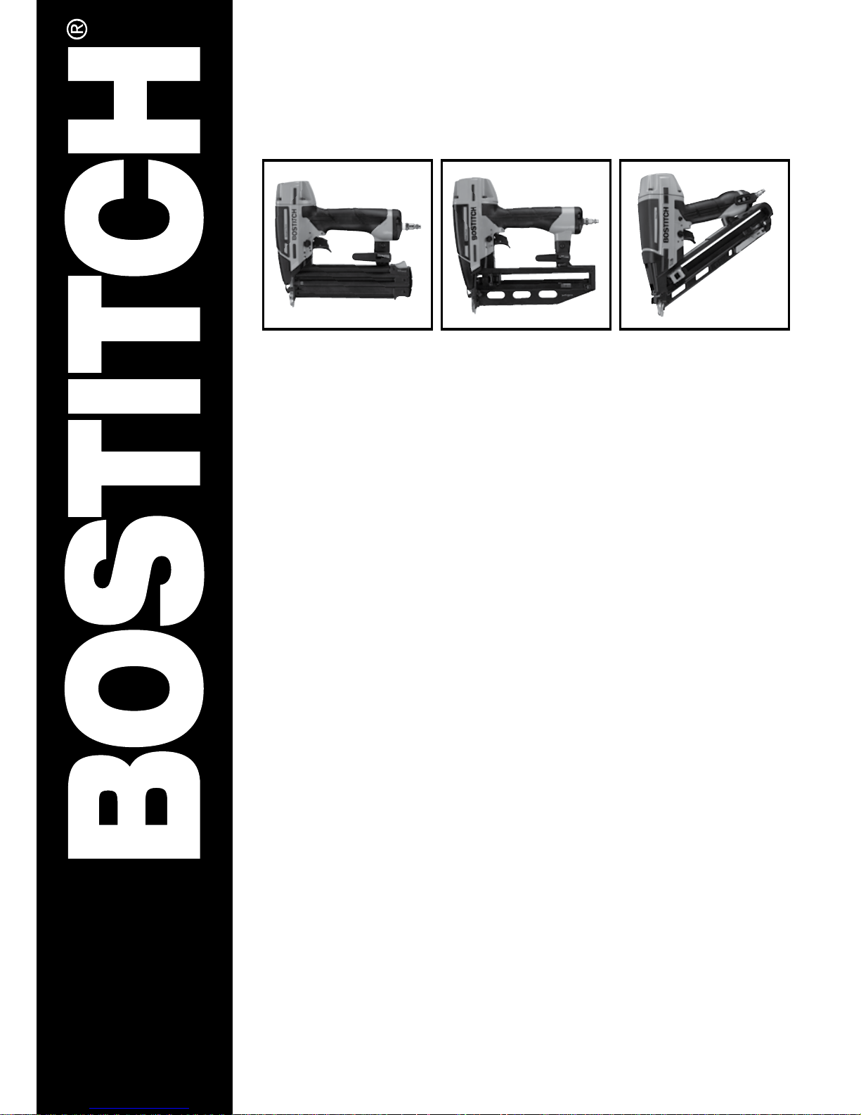
BT1855SP-A,
FN1664SP-A, DA1564SP-A
www.bostitch.eu
TOOL SAFETY AND
OPERATING INSTRUCTIONS MANUAL
Page 2
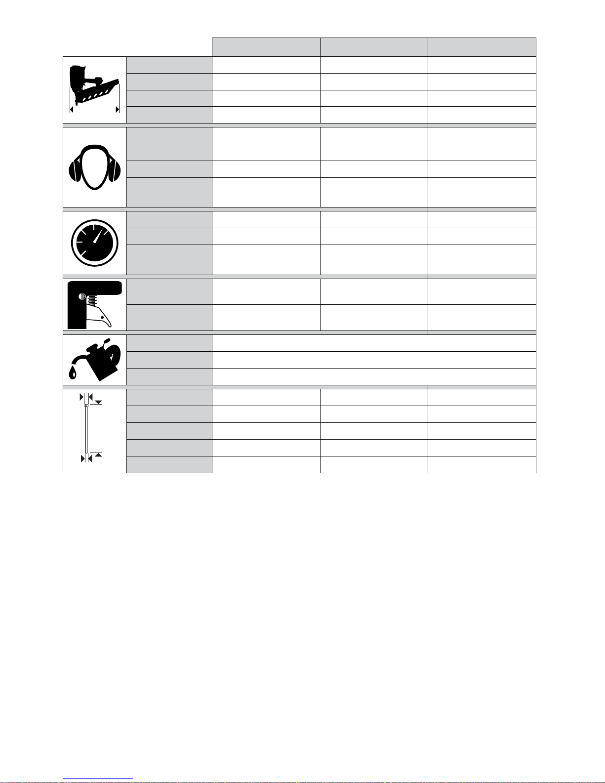
BT1855SP-A FN1664SP-A DA1564SP-A
Xmm
Length 235 mm 302 mm 325 mm
Height 240 mm 289 mm 307 mm
Width 70 mm 86 mm 97 mm
Weight 1.4 kg 1.8 kg 1.9 kg
Noise LPA / K
PA
84.46 dB / 4 dB 86.6 dB / 4 db 80.8 dB / 4 dB
Noise L
WA
/ K
WA
90.59 dB / 4 dB 93.3 dB / 4 db 93.75 dB / 4 dB
Noise L
PA
/ K
PA
77.6 dB / 4 dB 80.3 dB / 4 db 87.2 dB / 4 dB
Vibration /
Uncertainty
2.91 m/s
2
/ 1.46 m/s
2
3.19 m/s2 / 1.60 m/s
2
2.60 m/s2 / 1.30 m/s
2
BAR/
LTR
P max Bar 8.3 Bar 8.3 Bar 8.3 Bar
P min Bar 4.8 Bar 4.8 Bar 4.8 Bar
Air consumption per
shot @ 5.6 Bar
1.33 L 1.83 L 0.93 L
Actuation type 6 (Selectable) 6 (Selectable) 6 (Selectable)
Safety yoke type 2 2 2
Summer lubricant PREMOIL-20OZ
Winter lubricant WINTEROIL-20OZ
O-ring lubricant SB32
b
c
a
Fastener Name C-1 C AS-DA
Dimensions (a) 18GA / 1.3 mm 16GA / 1.54mm 15GA / 1.76mm
Dimensions (b) 15-50 mm 25-64 mm 32-64 mm
Head (c) 2 mm 1.6x2.8 mm 3.2 mm
Magazine capacity 100 100 100
Page 3

Page 4
DA1564SP
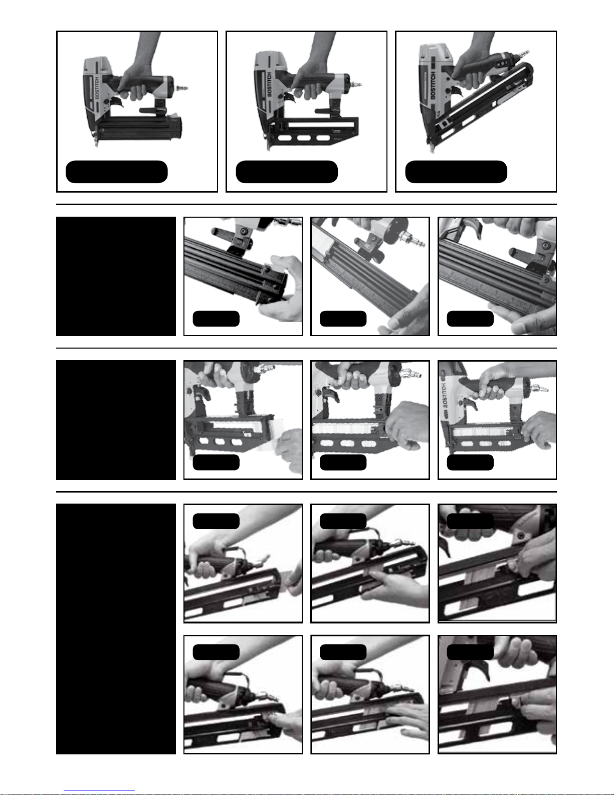
FIG 7 FIG 8 FIG 9
FN1664SP-A
FIG 4
FIG 5
FIG 6
BT1855SP-A FN1664SP-A DA1564SP-A
FIG 1
BT1855SP-A
FIG 2 FIG 2
FIG 10 FIG 11 FIG 12
Page 5
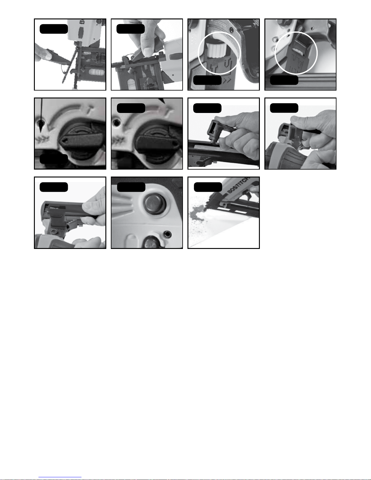
FIG 13
FIG 15a
FIG 17
FIG 21 FIG 22
FIG 18
FIG 19
FIG 20
FIG 15b
FIG 16
FIG 14
Page 6

TOOL SAFETY AND OPERATING INSTRUCTIONS
BEFORE OPERATING THIS TOOL, ALL OPERATORS SHOULD STUDY THIS MANUAL AND THE TOOL
TECHNICAL DATA TO UNDERSTAND AND FOLLOW THE SAFETY WARNINGS AND INSTRUCTIONS.
KEEP THESE INSTRUCTIONS WITH THE TOOL FOR FUTURE REFERENCE. IF YOU HAVE ANY
QUESTIONS, CONTACT YOUR BOSTITCH REPRESENTATIVE OR DISTRIBUTOR.
BEFORE OPERATING THIS TOOL, REFER TO TOOL DATA TABLE, COLUMN L IN THE TOOL TECHNICAL DATA
MANUAL TO IDENTIFY THE OPERATING SYSTEM ON YOUR TOOL.
BOSTITCH tools are precision built and designed for high speed, high volume fastening. They will deliver
efficient, dependable service when used correctly and with care. As with any fine power tool, the manufacturer’s
instructions must be followed for best results. Please study this manual and understand the safety warnings and
cautions before operating the tool. The instructions on installation, operation and maintenance should be read
carefully and the manuals kept for reference. Note: Additional safety measures may be required because of
your particular application of the tool. Contact your BOSTITCH representative or distributor with any questions
concerning the tool and it’s use.
m NOTE:
BOSTITCH tools have been designed to provide excellent customer satisfaction and are designed to achieve
maximum performance when used with precision BOSTITCH fasteners engineered to the same exacting
standards.
BOSTITCH cannot assume responsibility for product performance if any of our tools are used with fasteners
or accessories not meeting the specific requirements established for genuine BOSTITCH nails, staples and
accessories.
LIMITED WARRANTY
BOSTITCH is confident of the quality of its products and offers a guarantee for professional users of the product.
This guarantee statement is in addition to and in no way prejudices your contractual rights as a professional
user or your statutory rights as a private non-professional user. The guarantee is valid within the territories of the
Member States of the European Union and the European Free Trade Area.
If your BOSTITCH product becomes defective due to faulty materials or workmanship within 12 months from the
date of purchase, BOSTITCH guarantees to replace all defective parts free of charge or – at our discretion –
replace the unit free of charge provided that:
• The product has not been misused • The product has been subject to fair wear and tear; Driver blades,
bumpers, and O rings are considered normally wearing parts and are excluded • Repairs have not been
attempted by unauthorised persons • Proof of purchase is produced • The product is returned complete with all
original components • The product is returned at your expense together with proof of purchase to our regional
repair centre, or an authorised warranty centre.
If you wish to make a claim, contact your seller or check the location of your nearest authorised BOSTITCH repair
agent in the BOSTITCH catalogue or contact your BOSTITCH office at the address indicated in this manual.
SPECIAL REFERENCES
Only those fasteners that are specified in the operating instructions (see Tool Technical data) should be used
in the tool. The tool and the specified fasteners are to be considered as one single safety system for safety
purposes.
Repairs shall only be carried out by the authorized agents of BOSTITCH or by other experts, giving due regard
to the safety, operating and maintenance instructions in this manual, the specific tool manual and in the Tool
Technical Data.
Note: Experts are those who, as a result of professional training or experience, have acquired sufficient expertise
in the field of fastener driving tools as to be able to assess the safe condition of fastener driving tools.
Page 7

Stands or jigs for mounting the tool to a support, for example a work table, shall be designed and constructed by
the stand manufacturer in such a way that the fastener driving tools can be safely fixed for the intended use, thus
avoiding for example damage, distortion or displacement.
m SAFETY INSTRUCTIONS
EYE PROTECTION which provides protection against flying particles both from the FRONT and SIDE
should always be worn by the tool operator and others in the work area when loading, operating or
servicing this tool. Eye protection is required to guard against flying fasteners and debris, which could
cause severe eye injury. The employer and/or user must ensure that proper eye protection is worn.
Eye protection in accordance with 89/686/EEC/EEC, and with equal or greater grade than defined in
EN166 should be used. However all aspects of operators work, environment and other type/s of
machinery being used, should also be considered when selecting any personal protection equipment.
CAUTION: ADDITIONAL SAFETY PROTECTION may be required in some environments. For example,
the working area may include exposure to noise levels that can lead to hearing damage. The employer
and user should ensure that any necessary hearing protection is provided and used by the operator
and others in the work area. Some environments will require the use of head protection equipment.
When required, the employer and user must ensure that head protection is used.
m SAFETY INSTRUCTIONS FOR AIR SUPPLY AND CONNECTIONS
When connecting tools to the air supply, the fastener discharge area of the tool should be pointed away from
the operator and others in the working area. Place the discharge area of the tool over a test piece of material of
sufficient thickness which will fully accommodate the dimensions of the fastener to be driven. With hands clear
of the trigger and safety yoke mechanism, limbs and body clear of the discharge area the tool the air supply may
now be connected.
Do not use oxygen and combustible gases as an energy source for pneumatically operated tools.
Do not use bottled gases or an air supply where the maximum pressure in the line can potentially
exceed the maximum pressure stated in the specific tool manual as the tool may burst, possibly
causing injury. If the maximum air supply pressure could exceed these pressures, then a pressure
reducing valve with a downstream safety valve shall be built into the air supply.
Do not pull the trigger or depress the safety yoke while connecting to the air supply. The tool could cycle,
possibly causing injury.
The connector on the tool must not hold pressure when the air supply is disconnected. If a wrong fitting is used,
the tool can remain charged with air after disconnecting and thus will be able to drive a fastener even after the
air line is disconnected possibly causing injury.
Always disconnect air supply: 1) Before making adjustments; 2) When servicing the tool; 3) When clearing a jam;
4) When tool is not in use; 5) When moving to a different work area, as accidental actuation may occur, possibly
causing injury.
m SAFETY INSTRUCTIONS FOR LOADING TOOL
When loading the tool 1) Never place a hand or any part of the body in fastener discharge area of the tool; 2)
Never point the tool at self or anyone else; 3) Do not pull the trigger or depress the safety yoke as accidental
actuation may occur, possibly causing injury.
Note: See the separate Tool Technical Data manual for specific loading instructions and dimensions of
recommended fasteners.
SAFETY INSTRUCTIONS FOR TOOL OPERATION
• Always handle the tool with care: 1) Never engage in horseplay; 2) Never pull the trigger unless nose is
directed towards the work; 3) Keep others at a safe distance from the tool while tool is in operation as
accidental actuation may occur, possibly causing injury.
• The operator must not hold the trigger pulled on tools fitted with a safety yoke (sometimes called safety
Page 8

trip) except during fastening operation as serious injury could result if the safety yoke accidentally contacts
someone or something, causing the tool to cycle.
• Keep hands and body away from the discharge area of the tool. A tool fitted with a safety yoke may bounce
from the recoil of driving a fastener and an unwanted second fastener may be driven possibly causing injury.
• Check operation of the safety yoke mechanism frequently. Do not use the tool if the arm is not working
correctly as accidental driving of a fastener may result. Do not interfere with the proper operation of the safety
yoke mechanism.
• Do not drive fasteners on top of other fasteners as this may cause deflection of fasteners which could cause
injury.
• Do not drive fasteners close to the edge of the work piece as the wood may split allowing the fastener to be
deflected possibly causing injury.
SAFETY INSTRUCTIONS FOR TOOL MAINTENANCE
When working on air tools note the warnings in this manual, in the tool specific instructions and on the tool itself
and use extra care when evaluating problem tools.
m AIR SUPPLY AND CONNECTIONS
When connecting tools to the air supply, the fastener discharge area of the tool should be pointed away from
the operator and others in the working area. Place the discharge area of the tool over a test piece of material of
sufficient thickness which will fully accommodate the dimensions of the fastener to be driven. With limbs and
body clear of the discharge area the tool the air supply may now be connected.
To prevent accidental actuation and possible injury, always disconnect air supply:
1. Before making adjustments.
2. When servicing the tool.
3. When clearing a jam.
4. When tool is not in use.
5. When moving to a different work area, as accidental actuation may occur, possibly causing injury.
Do not use oxygen and combustible gases as an energy source for pneumatically operated tools.
Do not use bottled gases or an air supply where the maximum pressure in the line can potentially
exceed the maximum pressure stated in the specific tool manual as the tool may burst, possibly
causing injury.
• Compressors must be adequately dimensioned to ensure sufficient pressure and volumetric flow for the expected
use. Pressure drops in the air supply can reduce the tool’s driving power. Refer to the Tool Technical Data for
setting the correct pressure for the tool.
• Industrial air lines should be laid out on a gradient, with the highest point nearest the compressor. Easily
accessible water traps should be installed at the lowest points - Drain water traps at least daily, or more often
if necessary. Dirt and water in the air supply are major causes of wear in pneumatic tools. Connecting points
for the tool should be fitted with a filter/regulator/service unit directly at the connecting point. A filter will help
get the best performance and minimize wear. The filter must have adequate flow capacity for the specific
installation. The filter has to be kept clean to be effective in providing clean compressed air to the tool. Consult
the manufacturer’s instructions on the proper maintenance of your filter. A dirty and clogged filter will cause a
pressure drop which will reduce the tool’s performance.
• Junctions from industrial air lines to the tool should be from the top of the air line.
• The pressure regulator must have an operating pressure range of 0-8.79 bar.
• Air hoses should have a minimum of 10.6 Bar working pressure rating or 150 percent of the maximum pressure
that could be provided in the air system. The supply hose should contain a fitting that will supply “ quick
disconnecting” from the male plug on the tool.
• Ensure that the pressure supplied to the tool does not exceed the maximum allowable working pressure, called
ps max. (see Tool Technical Data), Initially set the supply pressure to the lowest recommended working pressure
(see Tool Technical Data).
• Check that the tool is functioning correctly by applying the nose to a piece of scrap wood and pulling the trigger
once or twice.
Page 9

LUBRICATION
• Frequent, but not excessive lubrication is required for best performance. Oil added through the air line
connection will lubricate the internal parts. For details of the correct lubricant see the Tool Technical Data. Do
not use detergent oil or additives as these lubricants will cause accelerated wear to the seals and bumpers in
the tool, resulting in poor tool performance and frequent tool maintenance.
• If no airline lubricator is used, add oil during use into the air fitting on the tool once or twice a day. Only a few
drops of oil (3-5) at a time are necessary. Too much oil will only collect inside the tool and will be noticeable in
the exhaust cycle.
• Cold weather operation. - For cold weather operation, near and below freezing, the moisture in the air line may
freeze and prevent the tool operation. We recommend the use of BOSTITCH Winter Formula air tool lubricant
or permanent antifreeze (ethylene glycol) as a cold weather lubricant.
Caution - To prevent frost or ice formation on the tool’s operating valves and mechanisms that could cause tool
failure, do not store the tool in a cold weather environment.
Note: Some commercial air line drying liquids are harmful to “O”-rings and seals - do not use these low
temperature air dryers without checking compatibility.
m WARNING! To prevent accidental injuries:
• Never place a hand or any other part of the body in fastener discharge area of tool.
• Never point tool at yourself or anyone whether it contains fasteners or not.
• Never engage in horseplay.
• Never pull the trigger unless the nose is directed towards the work.
• Always handle the tool with care.
• Use the Bostitch tool only for the purpose for which it was designed, such as: the finishing around doors,
windows and edging; draw bottoms, cabinet backs and cabinet making; picture framing and furniture trim.
These tools should not be used for anything other than wood to wood applications.
• Do not pull the trigger or depress the work safety yoke whilst loading the tool.
• To prevent accidental actuation and possible injury, always disconnect air supply.
1. Before making adjustments. 2. When servicing the tool. 3. When clearing a jam. 4. When tool is not in use.
5. When moving to a different work area, as accidental actuation may occur, possibly causing injury.
• Read the additional Safety & Operating instructions booklet before using tool.
• Do not use oxygen and combustible gases as an energy source for pneumatically operated tools.
• The operation of this tool can cause sparks and act as a source of ignition for flammable fuels and gases.
LOADING
m Warning! When loading the tool 1) Never place a hand or any part of the body in fastener discharge area
of the tool; 2) Never point the tool at self or anyone else; 3) Do not pull the trigger or depress the safety yoke as
accidental actuation may occur, possibly causing injury.
BT1855SP-A
1. Depress magazine release button and pull back magazine. (Fig 1)
2. With magazine fully open, insert fasteners. Points must be against bottom of magazine. (Fig 2)
3. Push magazine forward. Continue pushing until latch is engaged. (Fig 3)
FN1664SP-A
1. Load nails through the slot in the rear of the magazine and past retaining clip. (Fig 4)
2. Pull pusher back behind nail stick and release. (Fig 5)
3. Ensure magazine pusher is behind the last nail stick. (Fig 6)
Page 10

DA1564SP-A
This is equipped with dual load purpose magazines. Nails can be loaded in either method.
LOAD AND PULL PUSHER
1. Load nails through the slot in the rear of the magazine and past retaining clip. (Fig 7)
2. Pull pusher back behind nail stick and release. (Fig 8)
3. Ensure magazine pusher is behind the last nail stick. (Fig 9)
PULL PUSHER TO LOCK BACK AND LOAD
1. Pull pusher back until it is locked at the end of magazine. (Fig 10)
2. Load nails through the slot in the rear of the magazine and past retaining clip. (Fig 11)
3. Press the pusher button to release and allow the pusher to push behind the nails. (Fig 12)
4. Blow the magazine clean periodically to keep the pusher moving smoothly and to keep dirt and debris out of
the nail channel.
JAM CLEARANCE
m Warning! Always disconnect the air before clearing a jammed fastener.
Jam Clearing
1. Disconnect the air supply from the tool.
2. Relieve fasteners from pusher (DA1564SP-A & FN1664SP-A) or open the magazine (BT1855SP-A).
3. Open the jam clearing nose door by pulling down and then up on the latch (DA1564SP-A / FN1664SP-A only - Fig 13).
4. Remove the jammed fastener. In certain circumstances, pliers may be required to remove the fastener.
5. Close the jam clearing nose door latch (DA1564SP-A / FN1664SP-A only - Fig 14).
6. Pull pusher back behind fasteners (DA1564SP-A / FN1664SP-A) or close the magazine (BT1855SP-A).
“DIAL-A-DEPTH™” FASTENER CONTROL ADJUSTMENT (FIG 15a / 15b)
The DIAL-A-DEPTH™ Fastener Control adjustment feature provides close control of the fastener drive depth; from
flush with the work surface to shallow or deep countersink. First, set the air pressure for consistent drive in the
specific work, then use the DIAL-A-DEPTH™ Fastener Control adjustment to give the desired depth of drive.
ACTUATION MODE
m Warning! Always disconnect air supply before making adjustments as accidental actuation may occur,
possibly causing injury.
SAFETY YOKE TYPE
These models operate dierently from all other BOSTITCH tools. To provide maximum visibility for accurate
fastener placement, the safety yoke of this tool is normally in the “depressed” or “up” position. On all other
BOSTITCH tools and most other tools, the safety yoke is normally in the “extended” or “down” position.
This tool has a selectable actuation mode which determines if the tool drives fasteners in sequential or contact
actuation mode. In sequential mode, when the tip of the nose is placed on the work surface and the trigger is
pulled, the safety yoke moves out from the tool to detect the work surface. The tool nose tip must be in contact
with the work surface to actuate. If the safety yoke does not detect the work surface close enough to the nose of
the tool, the tool will not actuate.
In contact actuation mode, when the trigger is depressed and held, the safety yoke will move out from the tool.
Contacting the work surface with the tool nose, will actuate the safety yoke driving a fastener each time the work
surface is contacted.
SELECTABLE ACTUATION SYSTEM
These models feature a selectable actuation system that allows the user to choose between the following modes
of operation:
SEQUENTIAL ACTUATION MODE
The sequential actuation mode requires the operator to hold the tool against the work with the safety yoke
depressed before pulling the trigger. In order to drive additional fasteners, the trigger must be released and
the tool lifted away from the work, before repeating the above mentioned steps. This makes accurate fastener
Page 11

placement easier, for instance on framing, toe nailing and crating applications. The sequential actuation mode
allows exact fastener location without the possibility of driving a second fastener on recoil, as described under
Contact Actuation Mode (below). The sequential actuation mode has a positive safety advantage because it will
not accidentally drive a fastener if the tool is contacted against the work - or anything else - while the operator is
holding the trigger pulled.
CONTACT ACTUATION MODE
The common operating procedure on “Contact Actuation Mode” or “Bump Mode” tools is for the operator to
actuate the safety yoke while keeping the trigger pulled, thus driving a fastener each time the work is contacted.
This will allow rapid fastener placement on many jobs, such as sheathing, decking and pallet assembly. All
pneumatic tools are subject to recoil when driving fasteners. The tool may bounce, releasing the safety yoke and
if unintentionally allowed to re-contact the work surface with the trigger still actuated (finger still holding the
trigger pulled) an unwanted second fastener will be driven.
Warning: Tools must NOT be used in Contact Actuation Mode where changing from one working
position to another involves the use of ladders, stairs or similar structures such as roofs
SELECTING THE ACTUATION MODE (Fig 16-17):
To change the actuation mode, rotate the switch in the counterclockwise direction. The switch will lock
automatically when the indicating arrow is pointing down to the 3 nail icon stamped into the tool frame
(Contact Actuation Mode) or to a single nail icon stamped in the tool frame (Sequential Actuation Mode).
TOOL OPERATION CHECK
CAUTION: Remove all fasteners from tool before performing tool operation check.
m WARNING! If the tool has been dropped or you suspect tool damage perform tool operation check as defined
in the tool operation check section.
FULL SEQUENTIAL TRIP OPERATION
A) Without touching the trigger, press the safety yoke against the work surface.
THE TOOL MUST NOT CYCLE.
B) Hold the tool off the work surface and, avoiding to point the tool at self or others, pull the trigger.
THE TOOL MUST NOT CYCLE.
C) With the tool off the work surface, pull the trigger. Press the safety yoke against the work surface
THE TOOL MUST NOT CYCLE.
D) Without touching the trigger, press the safety trip against the work surface then pull the trigger.
THE TOOL MUST CYCLE.
E) With the safety trip still pressed against the work surface, pull the trigger again.
THE TOOL MUST NOT CYCLE.
CONTACT ACTUATION OPERATION
A) With the finger off the trigger, press the safety yoke against the work surface.
THE TOOL MUST NOT CYCLE.
B) Hold the tool off the work surface and, avoiding to point the tool at self or others, pull the trigger.
THE TOOL MUST NOT CYCLE.
C) With the tool off the work surface, pull the trigger. Press the safety yoke against the work surface
THE TOOL MUST CYCLE.
D) Without touching the trigger, press the safety yoke against the work surface then pull the trigger.
THE TOOL MUST CYCLE.
Page 12

TOOL USE
Having checked that the tool is working properly, press the nose against the work piece and pull the trigger.
Check whether the fastener has been driven as required.
• If the fastener is not driven deep enough, increase the air pressure by 5-6 psi (0.5 Bar) at a time,
checking the result after each adjustment. Do not exceed the maximum permissible working pressure
(see Tool Technical Data)
• If the fastener is driven too deeply, reduce the air pressure by 5-6 psi (0.5 Bar) at a time, checking the result after
each adjustment. Do not try to use less than the minimum working pressure (see Tool Technical Data).
Always try to work with the lowest possible air pressure. This will reduce the noise and vibration produced and
will extend the life of the internal components such as the bumper.
UTILITY HOOK INSTALLATION (Fig 18-20):
These tools include an additional utility hook suitable for storage and temporary hanging of the tool.
Warning: Always disconnect tool from air supply before making adjustments or before attempting any part
assembly or disassembly.
1. Make sure sequential actuation mode is selected (See Actuation Mode above)
2. Depress the utility hook release button on the hook body (Fig 18)
3. Slide the utility hook into the hook attachment slot. (Fig 19)
4. Release the utility hook release button and check to ensure that the hook is locked in position. (Fig 20)
m WARNING! Never use the utility hook with the contact actuation mode.
INTEGRATED AIR BLOWER (FIG 21, 22)
The DA1564SP-A has an integrated air blower that helps clean debris while working. Press the integrated air
blower button. Compressed air will be ejected out from front of the tool. Released the button to stop blowing air.
DO NOT DIRECT AIR STREAM AT BODY Risk of injury, do not direct air stream at persons or animals.
INTEGRATED PENCIL SHARPENER - DA1564SP-A
A pencil sharpener is integrated into the magazine for the operator’s convenience. To sharpen a pencil, insert any
standard pencil into the hole and rotate the pencil to the right (clockwise) to sharpen. Check compatability before use.
IN ADDITION TO THE OTHER WARNINGS IN THIS MANUAL OBSERVE THE FOLLOWING FOR SAFE OPERATION:
• Respect your BOSTITCH pneumatic fastening tool as a tool. It is not a toy. No Horseplay.
• Use the BOSTITCH pneumatic tool only for the purpose for which it was designed.
• Never use the tool in a manner that could cause a fastener to be directed towards the user or others in the work area.
• Do not use the tool as a hammer.
• Always carry the tool by the handle. Never carry the tool by the air hose. Never carry the tool with the trigger pulled.
• Do not alter or modify this tool from the original design or function without the written approval of BOSTITCH
• Always be aware that misuse and improper handling of this tool can cause injury to yourself and others.
• Never clamp or tape the trigger or safety yoke in an actuated position.
• Never leave a tool unattended with the air hose attached.
• Do not operate this tool if it does not contain a legible WARNING LABEL.
• Do not continue to use a tool that leaks air or does not function properly. Notify your nearest BOSTITCH representative
if your tool continues to experience functional problems.
• During operation, hold the tool in such a way that no injuries can be caused to the head or to the body should the tool
recoil increase due to a drop in the supply air pressure or hard areas within the work piece.
• Do not work close to corners or at the edge of the work piece. The fastener could slip out of the work piece, possibly
causing injury.
Page 13

• When transporting the tool, disconnect the air supply first.
• Check that the safety yoke (if present) and the trigger both function correctly.
• Do not dismantle or block any part of the tool, in particular not the safety yoke.
• Never perform “emergency repairs” without the proper equipment.
• Avoid weakening the tool by punching or engraving.
MAINTENANCE
Disconnect the tool from the air supply and completely empty the magazine before starting maintenance or
repairs. Note the warnings in this manual in the Tool Technical Data and on the tool itself and use extra care
when evaluating problem tools.
BOSTITCH replacement parts are recommended. Do not use modified parts or parts that will not give performance
equal to the original equipment.
When repairing a tool, make sure the internal parts are clean and lubricated. Use Parker “O”-Lube or equivalent
on all “O”-rings. Coat each “O”-ring with “O”-Lube before assembling. Use a small amount of oil on all moving
surfaces and pivots. After reassembly add a few drops of BOSTITCH Air Tool Lubricant through the airline before
testing.
For further instructions relating specifically to the maintenance of your tool, refer to the Tool Technical Data.
NOISE EMISSION (See Tool Technical Data)
The characteristic noise values for the tool have been determined in accordance with EN 12549 - “Acoustics Noise test code for fastener driving tools - Engineering Method.”
These values are tool related characteristic values and do not represent the noise development at the point of
use. Noise development at the point of use will depend for example on the working environment, the work piece,
the work piece support and the number of driving operations, etc.
Depending on the conditions at the workplace and the form of the work piece, individual noise attenuation
measures may need to be carried out, such as placing work pieces on sound damping supports, preventing work
piece vibration by means of clamping or covering, adjusting to the minimum air pressure required for the job, etc.
INFORMATION ON VIBRATION (see Tool Technical Data)
The characteristic vibration value for the tool has been determined in accordance with ISO/WD 8662-11
“Measurement of vibration in hand held power tools - Part 11 Fastener Driving Tools”.
This value is a tool related characteristic and does not represent the influence on the hand-arm system when using
the tool. An influence on the hand-arm system when using the tool will depend for example on the gripping force, the
contact force, the working direction, the working direction, the adjustment of the compressed air supply, the work
piece, the work piece support, etc.
Page 14

PROBLEM CAUSE CORRECTION
Failure to cycle Air supply restriction Check air supply equipment
Tool dry, lack of lubrication
Use BOSTITCH Air Tool Lubricant
Worn head valve O-rings (if present)
Replace O-rings
Broken cylinder cap spring
Replace cylinder cap spring
Head valve (if present) stuck in cap
Disassemble/Check/Lubricate
Lack of power; slow to cycle Air pressure too low
Check air supply equipment
Tool dry, lacks lubrication
Use BOSTITCH Air Tool Lubricant
Broken cylinder cap spring
Replace cylinder cap spring
O-rings/seals cut or cracked
Replace O-rings/seals
Exhaust blocked Check bumper, head valve spring, muer
Trigger assembly worn/leaks Replace trigger assembly
Cylinder sleeve not seated correctly
on bottom bumper
Disassemble to correct
Head valve dry Disassemble/lubricate
Trigger valve housing leaking air. O-ring cut or cracked Replace O-ring
Trigger valve stem leaks air O-rings/seals cut or cracked Replace O-rings/seals
Frame/nose leaks air O-ring or gasket is cut or cracked Replace O-ring or gasket
Bumper cracked/worn Replace bumper
Frame/cap leaks air Damaged gasket or seal Replace gasket or seal
Cracked/worn head valve bumper Replace bumper
Loose cap screws Tighten and recheck
Skipping fasteners; intermittent feed Worn bumper Replace bumper
Air restriction/inadequate air flow through quick
disconnect socket and plug
Replace quick disconnect fittings
Worn piston O-ring (if present) Replace O-ring, check driver
Tool dry, lacks lubrication Use BOSTITCH Air Tool Lubricant
Damaged pusher spring Replace spring
Low air pressure Check air supply system to tool
Loose magazine nose screw Tighten all screws
Fasteners too short for tool Use only recommended fasteners
Bent fasteners Discontinue using these fasteners
Wrong size fasteners Use only recommended fasteners
Leaking head cap gasket Tighten screws/replace gasket
Trigger valve O-ring cut/worn Replace O-ring
Broken/chipped driver Replace driver (check piston O-ring)
Dry/dirty magazine Clean/lubricate use BOSTITCH Air Tool Lubricant
Worn magazine Replace magazine
Fasteners jam in tool Driver channel worn Replace nose/check door
Wrong size fasteners Use only recommended fasteners
Bent fasteners. Discontinue using these fasteners
Loose magazine/nose screws Tighten all screws
Broken/chipped driver Replace driver (check piston O-ring)
Page 15

Page 16

Bostitch Australia
810 Whitehorse Road,
Box Hill,
Victoria, 3128
Australia
Tel: 1800 338 002
www.bostitchtools.com.au
Bostitch New Zealand
39 Business Parade North,
Highbrook, 2013,
Auckland
New Zealand
Tel: 0800 4782 6539
www.bostitchtools.co.nz
9R214333
FT73526-a-0516
 Loading...