

Page 1

Page 2
CONTENTS
Congratulations on your purchase of a
33bE
Audio Systems
Compact Disc Receiver. This product has been designed and
built to deliver the highest quality audio reproduction. We are
sure you'll enjoy listening to your favorite music with this
33bE
component as part of your car audio system. For best
results please consult a professional mobile electronics installer
for application advice or troubleshooting.
performance we recommend using The
To guarantee top
33bE
Link installation
accessories such as RCA interconnects, power cables, and
speaker wire. Thank you for choosing
33bS
Audio Systems
products for your mobile entertainment system. We can't change
the world, but we can make it sound better.
Installation
DIN Front-Mount (Method
DIN Rear-Mount (Method
Using the Detachable Front Panel
1
Wiring Connection
Operation
General Operation
Radio Operation
CD
Specification
Trouble Shooting
.....................................................................................................
Installing the unit
Removing the unit
........................................................................................ 7
.......................................................................................................
..................................................................................................
......................................................................................................
or
CDC
Operation 10
.........................................
.........................................................................................
4
A)
..................................................................................
...............................................................................................
.............................................................................................
...................................................................................
6)
..............................................................
4
4
5
5
6
8
8
9
...........................................................................................
....................................................
12
13
Page 3
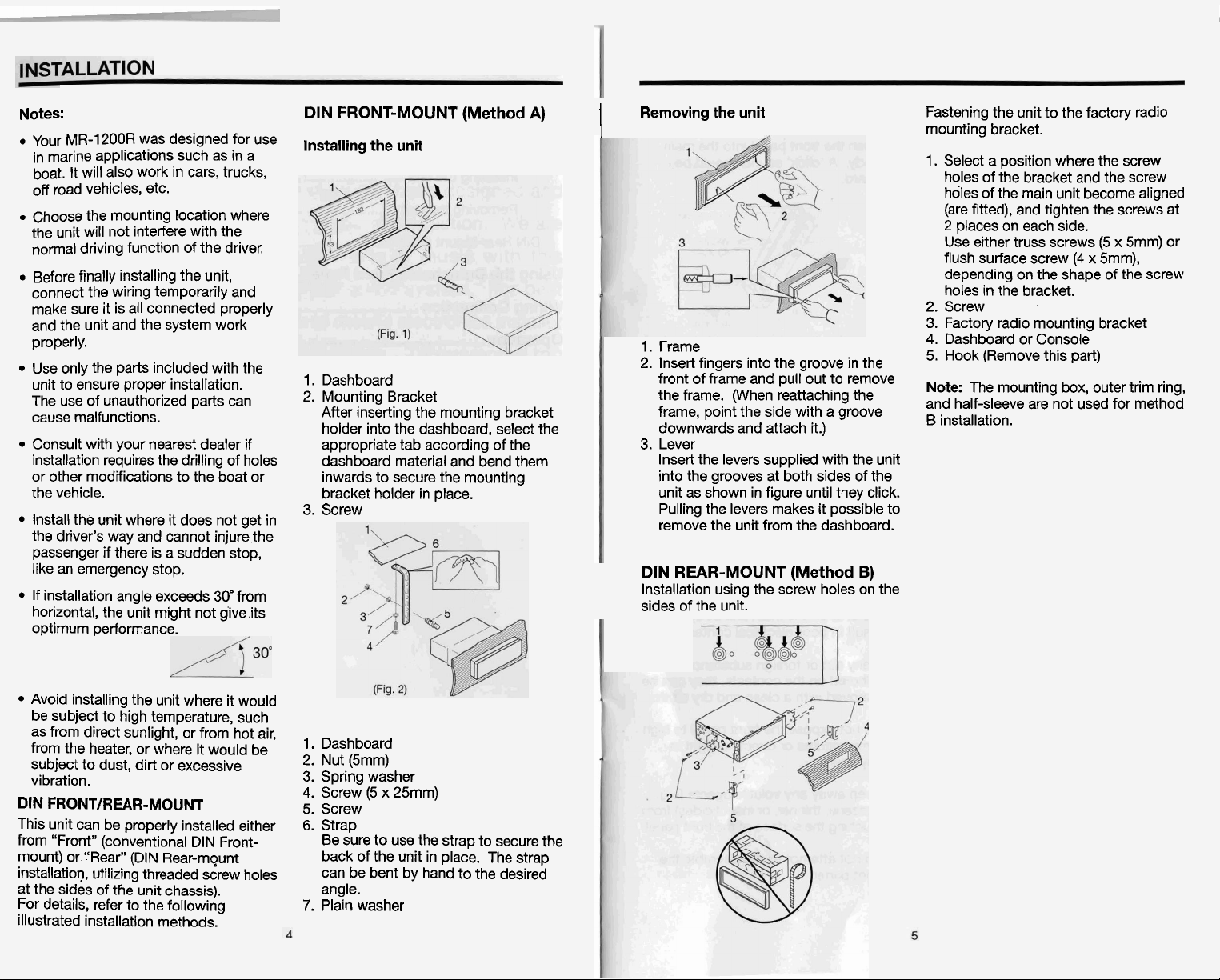
Notes:
Your MR-1200R was designed for use
in marine applications such as in a
boat. It will also work in cars, trucks,
off road vehicles, etc.
Choose the mounting location where
the unit will not interfere with the
normal driving function of the driver.
Before finally installing the unit,
connect the wiring temporarily and
make sure it is all connected properly
and the unit and the system work
properly.
Use only the parts included with the
unit to ensure proper installation.
The use of unauthorized parts can
cause malfunctions.
Consult with your nearest dealer if
installation requires the drilling of holes
or other modifications to the boat or
the vehicle.
Install the unit where it does not get in
the driver's way and cannot
passenger if there is a sudden stop,
like an emergency stop.
If installation angle exceeds 30efrom
horizontal, the unit might not give its
optimum performance.
injure,the
DIN
FRONT-MOUNT (Method
Installing the unit
1.
Dashboard
2.
Mounting Bracket
After inserting the mounting bracket
holder into the dashboard, select the
appropriate tab according of the
dashboard material and bend them
inwards to secure the mounting
bracket holder in place.
3. Screw
A)
Removing the unit
!
1.
Frame
2. Insert fingers into the groove in the
front of frame and pull out to remove
the frame. (When reattaching the
frame, point the side with a groove
downwards and attach it.)
3.
Lever
Insert the levers supplied with the unit
into the grooves at both sides of the
unit as shown in figure until they click.
Pulling the levers makes it possible to
remove the unit from the dashboard.
DIN
REAR-MOUNT (Method
Installation using the screw holes on the
sides of the unit.
B)
Fastening the unit to the factory radio
mounting bracket.
1. Select a position where the screw
holes of the bracket and the screw
holes of the main unit become aligned
(are fitted), and tighten the screws at
2
places on each side.
(5
Use either truss screws
flush surface screw (4 x
depending on the shape of the screw
holes in the bracket.
2. Screw
3.
Factory radio mounting bracket
4. Dashboard or Console
5.
Hook (Remove this part)
Note:
The mounting box, outer trim ring,
and half-sleeve are not used for method
B installation.
x 5mm) or
5mm),
Avoid installing the unit where it would
be subject to high temperature, such
as from direct sunlight, or from hot air,
from the heater, or where it would be
subject to dust, dirt or excessive
vibration.
DIN FRONTIREAR-MOUNT
This unit can be properly installed either
from "Front" (conventional DIN
mount) or '.'Rearw (DIN Rear-mqunt
installation, utilizing threaded screw holes
at the sides of the unit chassis).
For details, refer to the following
illustrated installation methods.
Front-
1. Dashboard
2.
Nut (5mm)
3.
Spring washer
4. Screw (5 x
5. Screw
6.
Strap
Be sure to use the strap to secure the
back of the unit in place. The strap
can be bent by hand to the desired
angle.
7.
Plain washer
25mm)
Page 4

ABLI (RONT PANEL
c
!
WIRING CONNECTION
To Detach the Front pafine'
store
being
Pnd the fr
8
,tb toward
tp&
reWnoved.
Case
1.
Press the
panel will flip down.
Open
2.
Remove the front panel
in the middle and pulling
3,
For
in the supplied protectivo
immediately
open
button
&
Front
Panel
safekeeping,
aher
Protective
t
graspirfl!
,,.
front
p:i
To Reinstall the Front Panel
1.
Push the front panel into the main
body. A 'click' sound should be
heard.
2.
Note that if the front panel fails to lock
in
Dosition ~ro~erlv, Dress control
bu'tton mai not fuiction and display
may be missing some segments.
OPEN
Pressing the
ceinstall the front panel again.
ecautions when Handling
1.
Do not drop the front panel.
2. Do not put pressure on the display or
control buttons when detaching or
reinstalling the front panel.
3.
Do not touch the contacts on the front
panel or on the main unit body. It may
result in poor electrical contact.
button and then
-
MAIN
I
BLACK
L
..,..--
4-SPEAKERS SYSTEM
GREEN
ANTENNACONNECTOR
MEMORY YELLOW
e
BACK-UP
GROUND
(B-)
POWER BLUE
ANTENNA
;.
2-SPEAKERS SYSTEM.
Note:
1.
For 2-speakers system, green, violet, white/black and grey/black wire leads are
unconnected and isolated.
2.
For 2-speakers system, keep the fader indicator at center position to maintain the
existing volume level.
UNIT
1
[
AUX INPUT
11
11111111
111
111
FRONT RCA CABLE Rch RED
-...,I I 1 11
I I I,.---
4-SPEAKERS SYSTEM
I
IRROWM
>-.
.
-
. .
.
.
.-...,.
2-SPEAKERS SYSTEM
Rch RED
Lch WHITE
,
LCh WHITE
Lch WHITE
...
4.
Front
Push
the
main
body. A 'click'
heard.
Panel
front
metal
souoOd shouldh
"nto the
4.
If any dirt or foreign substances
adhered on the contacts, they can be
removed with a clean and dry cloth.
5.
Do not expose the front panel to high
temperatures or direct sunlight in
anywhere.
6.
Keep away any volatile agents (e.g.
benzene, thinner, or insecticides) from
touching the surface of the front panel.
7.
Do not attempt to disassemble the
front panel.
Page 5

Page 6

Page 7

 Loading...