

Page 1
Owner’s Manual
Before using this unit, carefully read “USING THE UNIT SAFELY” and “IMPORTANT NOTES” (the leaet “USING THE UNIT SAFELY” and the Owner’s
Manual (p. 19)). After reading, keep the document(s) where it will be available for immediate reference.
© 2019 Roland Corporation
Page 2
Panel Descriptions
Top Panel
1
2
3 4
2
5
6
7 8 9 10
11 12
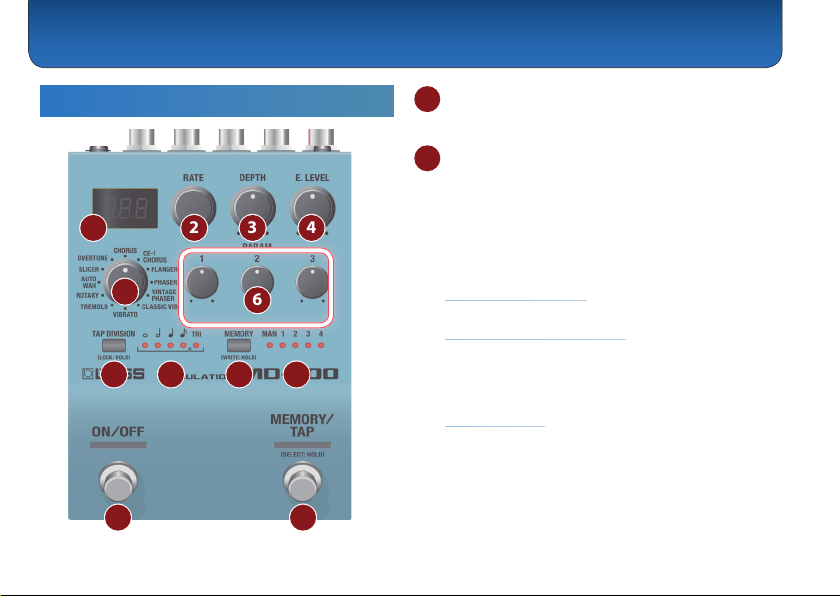
1 Display
Shows the parameters and the values.
2 [RATE] knob
Adjusts the speed at which the eect sound changes, or
switches memories.
The display changes each time you press the knob.
Rate (frequency) & Rate (tempo/frequency) &
Memory & Rate (frequency) …
Example indications
Rate (frequency)
0.01 Hz = “0.01”, 1 Hz = “1.00”, 10 Hz = “10.0”
Rate (tempo/frequency)
tempo: 120 = “120.”, tempo: 1000 = “1.0K.”,
tempo: 10000 = “10K.”
* When the mode is ROTARY, this switches the speaker’s rotation
speed between SLW (slow) and FST (fast).
Memory
MANUAL = “MAN”, memory 1–9 = “M-1”–“M-g”, memory
10–99 = “M10”–“Mgg”, memory 100–127 = “M.00”–“M.27”
Page 3

Panel Descriptions
3 [DEPTH] knob
Adjusts the depth to which the eect sound is
modulated.
* When the mode is ROTARY, this adjusts the amount of preamp
distortion. When the mode is SLICER, this adjusts the balance
between the eect sound and the direct sound.
4 [E. LEVEL] knob
Adjusts the volume of the eect sound.
In some modes, this adjusts the balance between eect
sound and direct sound.
5 Mode knob
Selects the eect.
Mode Explanation
CHORUS (CHO)
CE-1 CHORUS (CE1)
FLANGER (FLG)
PHASER (PHS)
VINTAGE PHASER
(VPH)
CLASSIC VIBE (CVB)
Chorus sound using cutting-edge BOSS
technology.
A chorus sound that models the CE-1.
Produces a anging eect.
Produces a phase eect.
Models the MXR PHASE90 produced
during the 1970s.
Models the Uni-Vibe.
Mode Explanation
VIBRATO (VIB)
TREMOLO (TRM)
ROTARY (ROT)
AUTO WAH (AWH)
SLICER (SLI)
OVERTONE (OVT)
Vibrato with a unique eect.
An eect that cyclically changes the
volume.
Realistically reproduces the sound of a
rotary speaker.
Cyclically modulates a lter to
automatically create a wah eect.
Cyclically cuts the sound to create a
variety of slice patterns.
Adds new overtones to create
resonance and depth not present in
the original sound.
3
Page 4

Panel Descriptions
6 PARAM [1]–[3] knob
Set the parameters. The parameters dier depending on the mode.
Holding down the [RATE] knob and turning the [DEPTH], [E. LEVEL], and PARAM [1] to [3] knobs, to indicate the parameter
name (abbreviation) on the display while changing the value.
Mode PARAM 1 PARAM 2 PARAM 3
CHORUS (CHO)
CE-1 CHORUS (CE1)
FLANGER (FLG)
PHASER (PHS)
VINTAGE PHASER
(VPH)
SWT
(SWEETNESS)
Higher values create a more
enveloping sound.
TYP
(TYPE)
CHO: Chorus sound of the CE-1
VIB: Vibrato sound of the CE-1
(RESONANCE)
RES
Adjusts the amount of resonance
(feedback).
(RESONANCE)
RES
Adjusts the amount of resonance
(feedback).
TYP
(TYPE)
THR (THRU): Only phaser sound.
(CRUNCH): Distortion is added.
CRH
LOC (LOW CUT FREQUENCY)
Adjusts the tonal character of the
low-frequency region.
LO (LOW LEVEL)
Adjusts the tonal character of the
low-frequency region.
MAN (MANUAL)
Adjusts the center frequency at
which the eect is applied.
MAN (MANUAL)
Adjusts the center frequency at
which the eect is applied.
DRV (DRIVE)
Adjusts the amount of distortion
when CRH (CRUNCH) is selected.
HIC (HIGH CUT FREQUENCY)
Adjusts the tonal character of the
high-frequency region.
HI (HIGH LEVEL)
Adjusts the tonal character of the
high-frequency region.
LOC (LOW CUT FREQUENCY)
Cuts the frequency components
below the specied frequency.
With the FLT (at) setting, the low
cut lter is not applied.
LOC (LOW CUT FREQUENCY)
Cuts the frequency components
below the specied frequency.
With the FLT (at) setting, the low
cut lter is not applied.
TON (TONE)
Adjusts the tonal character when
CRH (CRUNCH) is selected.
4
Page 5

Panel Descriptions
Mode PARAM 1 PARAM 2 PARAM 3
CLASSIC VIBE (CVB)
VIBRATO (VIB)
TREMOLO (TRM)
ROTARY (ROT)
AUTO WAH (AWH)
(TYPE)
TYP
THR (THRU): Only phaser sound.
(FUZZ): Distortion is added.
FUZ
(TONE)
TON
Higher values produce more
complex modulation.
TYP
(TYPE)
TRM (TREMOLO): Cyclically modulates
the volume.
(PAN): By alternately changing
PAN
the volume of left and right, this
produces the impression that the
sound is moving between the left
and right speakers when heard in
stereo. (If you don't use stereo output, this will
not produce the intended eect.)
SLW
(SLOW SPEED)
Adjusts the SLW (slow) rotation
speed.
(RESONANCE)
RES
Adjusts the depth of the wah
eect in the region of the center
frequency.
DRV (DRIVE)
Adjusts the amount of distortion
when FUZ (FUZZ) is selected.
D/E (DIRECT/EFFECT BALANCE)
Adjusts the volume of the direct
sound and the eect sound.
WAV (WAVEFORM)
Selects the type of wave.
FST (FAST SPEED)
Adjusts the FST (fast) rotation
speed.
FRQ (FREQUENCY)
Species the center frequency of
the wah eect.
TON (TONE)
Adjusts the tonal character when
FUZ (FUZZ) is selected.
TON (TONE)
Adjusts the tonal character.
TON (TONE)
Adjusts the tonal character.
R/H (ROTOR / HORN BALANCE)
Adjusts the balance between the
horn and the rotor.
TYP (FILTER TYPE)
LPF: Low-pass lter. Only the low-
frequency region is passed.
HPF: High-pass lter. Only the
high-frequency region is passed.
BPF: Band-pass lter. Only a
specic frequency region is passed.
5
Page 6

Panel Descriptions
Mode PARAM 1 PARAM 2 PARAM 3
SLICER (SLI)
OVERTONE (OVT)
7 [TAP DIVISION] button
Species the rate as a note value relative to the BPM.
Preventing accidental operation (panel lock)
By long-pressing the [TAP DIVISION] button, you can
switch between enabling (unlocking) or disabling
(locking) operation of the knobs and buttons.
If you attempt an operation while the unit is locked, the
display indicates “LCK.”
PTN
(PATTERN)
Selects the pattern at which the
sound is sliced.
LWR
(LOWER LEVEL)
Adjusts the overtone one octave
below.
ATK (AT TACK )
Adjusts the attack volume of the
slice pattern.
UNI (UNISON LEVEL)
Adjusts the volume at which sound
that is slightly pitch-shifted is added
to the direct sound.
8 TAP DIVISION indicator
Indicates the rate as a note value, relative to quarternotes (100%) of the interval at which you press the
pedal.
TAP DIVISION indicator
ª ˇ ¸ ˙
(
( (
(
( (
(
( (
6
DTY (DUTY)
Adjusts the length of sound for the
slice pattern.
UPR (UPPER LEVEL)
Adjusts the overtone one octave
above.
Explanation
TRI
Whole note (25%)
Whole-note triplet (38%)
Half note (50%)
Half-note triplet (75%)
Quarter note (100%)
Quarter-note triplet (150%)
(
( (
Eighth note (200%)
Eighth-note triplet (300%)
Page 7

Panel Descriptions
9 [MEMORY] button
Switches or saves memories (MANUAL, 1–127) (p. 10).
The memory is switched each time you press the
[MEMORY] button. You can also switch memories by
holding down the [MEMORY] button and turning the
[RATE] knob.
10 MEMORY indicator
Indicates the currently selected memory.
If a memory 5–127 is selected, the indicator is unlit.
11 [ON/OFF] switch
Turns the eect on/o.
12 [MEMORY/TAP] switch
Switches memories (p. 10).
Long-press the [MEMORY/TAP] switch to select tap
mode.
By pressing the switch in time with the tempo of the
song you're performing, you can specify a speed of
modulation that matches the song.
When the mode is ROTARY, this switches the rotation
speed of the speaker.
MEMO
The function of the footswitch can be changed by
“MFC” (MEMORY FUNCTION).
7
Page 8

Panel Descriptions
Rear Panel (Connecting Your Equipment)
* To prevent malfunction and equipment failure, always turn down the
volume, and turn o all the units before making any connections.
A B C
A
INPUT (A/MONO, B) jacks
Connect your guitar, bass, or eect unit here.
Use the A/MONO and B jacks if connecting an eect
unit that has stereo output. Use only the A/MONO jack
if using this unit in mono.
Turning On/O the Power
The INPUT A/MONO jack also operates as the power
switch. The power turns on when you insert a plug into
the INPUT A/MONO jack.
8
D
When powering up
Power-up equipment such as your guitar amp last.
When powering down
Power-down equipment such as your guitar amp rst.
* Before turning the unit on/o, always be sure to turn the volume
down. Even with the volume turned down, you might hear some
sound when switching the unit on/o. However, this is normal and
does not indicate a malfunction.
B OUTPUT (A/MONO, B) jacks
Connect this jack to your amp or monitor speakers.
Use only the OUTPUT A/MONO jack if using this unit in
mono. Even sound that is input in stereo is output in
mono.
The input/output jacks can be used to utilize the insert
loop function (p. 13).
C CTL 1, 2/EXP jack
Using the jack as CTL 1, 2
You can connect a footswitch (sold separately: FS-5U,
FS-6, FS-7) and use it to tap-input the rate or switch
memories (p. 11).
Page 9

Panel Descriptions
Using the jack as EXP
You can connect an expression pedal (sold separately:
EV-30, Roland EV-5, etc.) and use it to control the rate or
the volume of the eect sound (p. 13).
* Use only the specied expression pedal. By connecting any other
expression pedals, you risk causing malfunction and/or damage
to the unit.
D DC IN jack
An AC adaptor (sold separately: PSA-S series) can be
connected to this jack.
* Use only the specied AC adaptor (sold separately: PSA-S series)
and plug it into an AC outlet of the correct voltage.
* If the AC adaptor is connected while power is on, the power supply
is drawn from the AC adaptor.
Side Panel (Connecting Your Equipment)
F
E
MIDI jacks
E
Use a TRS/MIDI connecting cable (sold separately:
BMIDI-5-35) to connect an external MIDI device. You can
use an external MIDI device to switch the memories of
this unit.
* Do not connect an audio device here. Doing so will cause
malfunctions.
F USB port (for program updates only)
Connect your computer using a commercially available
USB cable that supports USB 2.0.
* Do not use a micro USB cable that is designed only for charging a
device. Charge-only cables cannot transmit data.
* This is used only for program updates.
9
Page 10

Saving and Switching Memories
Saving to Memory
Here’s how to save eect settings that you edited.
1. Long-press the [MEMORY] button.
The display indicates “Wrt.”
2. Turn the [RATE] knob to select the save-
destination (MAN, 1–127).
You can also select the save-destination by pressing
the [MEMORY] button.
If you decide to cancel, press the [TAP DIVISION]
button.
3. Long-press the [MEMORY] button to conrm
the save-destination.
The memory is saved.
* If you save to MAN, the settings of the panel are applied as the
values for MODE, DEPTH, E.LEVEL, and PARAM 1–3.
10
Switching Memories
Here’s how to recall a saved memory.
1. Press the [MEMORY] button to select a
memory.
Each time you press the button, you cycle through
the memories in the order of “MAN (manual) 0 1
0 2 0 3 0 4 ...1270 MAN...”
You can also switch memories by holding down the
[MEMORY] button and turning the [RATE] knob.
* The MEMORY indicator is unlit if a memory 5–127 is selected.
MEMO
You can specify the memory switching range by editing
the
ETF (EXTENT FROM)
What is “MAN” (manual)?
This unit normally applies the eect according to the
settings that are saved in memory, but if you select
MAN (manual) the eect is applied according to the
positions of the panel knobs. Even in this case, the rate
and TAP DIVISION recall the settings that are written to
MAN (this can be changed).
and
ETT (EXTENT TO)
settings (p. 14).
Page 11

Overall Settings (Menu)
Basic Operation
1. Press the [TAP DIVISION] button and
[MEMORY] button simultaneously.
You enter menu mode.
2. Turn the [RATE] knob to select a parameter, and
then press the [RATE] knob.
The value is displayed.
3. Turn the [RATE] knob to edit the value.
4. Press the [RATE] knob.
5. Press the [TAP DIVISION] button and
[MEMORY] button simultaneously.
You exit menu mode.
Assigning functions to external pedals
You can connect footswitches (sold separately: FS-5U, FS-6, FS-7)
to the CTL 1, 2/EXP jack, and use them to tap-input the rate or to
switch memories.
Use the menu items “C1F” or “C2F” to make these settings (p.
12).
FS-5U FS-6, FS-7
CTL 1
CTL 2 C TL 1
FS-5U
FS-5U×2
CTL 2 CTL 1
FS-6, FS-7
CTL 2
CTL 1
11
Page 12

Overall Settings (Menu)
MEMORYMEMORY
MEMORYMEMORY
MEMORYMEMORY
MEMORYMEMORY
MEMORYMEMORY
MEMORYMEMORY
Menu Parameter List
About the
5 Can be set and saved for each memory by the “Saving to Memory” (p.
10) operation. If you do not perform this operation, the settings are lost
when you switch memories.
5 Can be set and saved for each memory if the preference (SWP/MEP/C1P/
C2P/EPP) is set to MEM (MEMORY). To save, refer to “Saving to Memory”
(p. 10).
If set to SYS (SYSTEM), the settings common to the unit are used. Function
settings are saved automatically.
Parameter Explanation
tHd
(TEMPO HOLD)
12
mark
oFF: Operates using the tempo/rate of
the memory.
on: Operates using the tempo/rate of the
previous memory.
Parameter Explanation
Specify the functions of the [ON/OFF]
SWF
(ON/OFF SWITCH
FUNCTION)
MFC
(MEMORY SWITCH
FUNCTION)
C1F
(CTL1 FUNCTION)
C2F
(CTL2 FUNCTION)
switch, [MEMORY/TAP] switch, and
footswitches connected to the CTL 1, 2/
EXP jack.
* The functions that can be assigned dier
depending on the switch.
oFF: No operation.
(ON/OFF SWITCH) : Turns the eect on/o.
SW
(MOMENT) : The eect is on only while you
MoM
hold down the switch.
(MANUAL) : Selects manual.
MAn
(MEMORY 1) –M-g (MEMORY 9) : Selects
M-1
memory 1–9.
(MEMORY 10) –Mgg (MEMORY 99) : Selects
M10
memory 10–99.
(MEMORY 100) –M.27 (MEMORY 127) : Selects
M.00
memory 100–127.
(MEMORY UP) : Increments the memory
MUP
number according to the MEMORY EXTENT
setting.
If you long-press the switch, it operates
as tap tempo.
Mdn (MEMORY DOWN) : Decrements the memory
number according to the MEMORY EXTENT
setting. If you long-press the switch, it operates
as tap tempo.
(MEMORY UP, ON/OFF) : Increments the memory
MUP.
number according to the MEMORY EXTENT
setting. Long-press the switch to turn the eect
on/o.
(MEMORY DOWN, ON/OFF) : Decrements the
MDN.
memory number according to the MEMORY
EXTENT setting. Long-press the switch to turn
the eect on/o.
(TAP TEMPO) : Operates as tap tempo.
tAP
Page 13

Overall Settings (Menu)
MEMORYMEMORY
MEMORYMEMORY
MEMORYMEMORY
MEMORYMEMORY
Parameter Explanation
EPF
(EXPRESSION FUNCTION)
EPN
(EXPRESSION MIN)
EPM
(EXPRESSION MAX)
Species the function of an expression
pedal connected to the CTL 1, 2/EXP jack.
oFF: No operation.
(RATE) : The same operation as the
RAT
[RATE] knob.
(DEPTH) : The same operation as the
DPT
[DEPTH] knob.
(E.LEVEL) : The same operation as the
Elv
[E.LEVEL] knob.
(PARAM1) : The same operation as the
PR1
[PARAM 1] knob.
(PARAM2) : The same operation as the
PR2
[PARAM 2] knob.
(PARAM3) : The same operation as the
PR3
[PARAM 3] knob.
Species the variable range of the
parameter controlled by EXPRESSION
FUNCTION. The variable range diers
depending on the parameter.
Parameter Explanation
Selects the position at which the external
eect unit is connected.
OFF: The insert loop function is not used.
(PRE) : Connect before the MD-200’s
PRE
eect.
Guitar&External Eector&MD-200&
PST (POST) : Connect after the MD-200’s
eect.
Guitar&MD-200&External Eector&
ILP
(INSERT LOOP POSITION)
Insert Loop Function
AMP
You can connect an external eect unit
between the OUTPUT A/MONO jack and
the INPUT B jack, and use it in conjunction
with the MD-200’s eect.
For some eect types, you can specify
“before or after distortion.”
External
Eector
Guitar
13
Page 14

Overall Settings (Menu)
Parameter Explanation
INS
(INSERT LOOP SWITCH)
SWP
(ON/OFF SWITCH FUNCTION
PREFERENCE)
MEP
(MEMORY SWITCH
FUNCTION PREFERENCE)
C1P
(CTL1 FUNCTION
PREFERENCE)
C2P
(CTL2 FUNCTION
PREFERENCE)
EPP
(EXPRESSION FUNCTION
PREFERENCE)
ETF (EXTENT FROM)
ETT (EXTENT TO)
G/B
(GUITAR/BASS MODE)
Turns the insert loop function on/o.
OFF, ON
MEM (MEM) : The setting in memory is used.
(SYS) : The controller’s function is xed
SYS
regardless of memory.
Specify the memory switching range
(MEMORY EXTENT FROM–TO).
(MANUAL), M-1 (MEMORY 1) –M.27
MAN
(MEMORY 127)
Species the response of the FLANGER,
PHASER, and AUTO WAH.
(Guitar): Settings suitable for guitar.
GTR
(Bass): Settings suitable for bass.
BAS
14
Parameter Explanation
CMD
(CHORUS CONTROL MODE)
Species the function of E.LEVEL when
CHORUS or CE-1 CHORUS are selected as
the mode.
If this is set to ELV (EFFECT LEVEL), the
E.LEVEL knob adjusts the balance between
the direct sound and the eect sound.
If this is set to TTL (TOTAL LEVEL), the
E.LEVEL knob adjusts the combined
volume of the direct sound and the eect
sound. In this case, the direct sound and
eect sound are mixed at a ratio of 1:1.
Species the MIDI receive channel.
RCH
(MIDI RECEIVE CHANNEL)
If this is “oFF,” MIDI messages are not
received.
1–16, oFF
Species the MIDI transmit channel.
If this is “oFF,” MIDI messages are not
TCH
(MIDI TRANSMIT CHANNEL)
transmitted.
If this is RECEIVE, the same setting as the
receive channel is used.
1–16, RCv
Pin (PC IN)
Species whether program changes are
received (on) or not received (oFF).
(RECEIVE), oFF
Page 15

Overall Settings (Menu)
Parameter Explanation
Pot (PC OUT)
CCI (CC IN)
CCO (CC OUT)
Species whether program changes
are transmitted (on) or not transmitted
(oFF).
Correspondence between memories
and program numbers
Memory Program number
MAN
MEMORY 1–127
Species whether control changes are
received (on) or not received (oFF).
By receiving CC messages, this unit
lets you use MIDI to control the same
operations as a knob or footswitch.
Species whether control changes are
transmitted (on) or not transmitted
(oFF).
1
2–128
Parameter Explanation
RTC (RATE CC)
DPC (DEPTH CC)
ELC (E.LEVEL CC)
P1C (PARAM1 CC)
P2C (PARAM2 CC)
P3C (PARAM3 CC)
SWC
(ON/OFF SWITCH CC)
Specify the controller number
corresponding to each controller.
oFF, 1–31, 64–95
MEC (MEMORY CC)
C1C (CTL1 CC)
C2C (CTL2 CC)
EPC (EXPRESSION CC)
EFC
(EFFECT ON/OFF CC)
SYN (SYNC)
Species the tempo clock to which this
unit will synchronize.
(INTERNAL): Synchronize to the internal
int
tempo.
(AUTO): Normally synchronize to
Aut
the internal tempo, but if MIDI clock is
being input via the MIDI IN connector,
synchronize the tempo to MIDI clock. If
you’re using the MD-200 as a slave device,
choose the “Aut” setting.
15
Page 16

Overall Settings (Menu)
Parameter Explanation
RTS
(REALTIME SOURCE)
MTH (MIDI THRU)
P1–Pg
(P1–P9)
P10–Pgg
(P10–P99)
P.00–P.28
(P100–P128)
Species the source of realtime messages
that are output to the MIDI OUT jack.
(INTERNAL) : Internal realtime messages
int
are the source.
(MIDI) : Realtime messages from the
Mid
MIDI IN jack are the source.
Species whether MIDI messages received
at the MIDI IN connector are retransmitted
without change from the MIDI OUT
connector (on) or are not retransmitted
(oFF).
Specify the memory corresponding to the
received program number. Bank select is
ignored (received regardless).
If this is OFF, the eect turns o.
OFF, MAN, M-1–M.27
16
Page 17

Appendix
Returning to the Factory Settings (Factory Reset)
Here's how to return the MD-200 to its factory-set state.
1. While holding down the [ON/OFF] switch and
[MEMORY/TAP] switch, turn on the power
(insert a plug into the INPUT A/MONO jack).
The display indicates “FCt.”
2. Press the [MEMORY/TAP] switch.
The display indicates “Sur.”
If you decide to cancel, press the [MEMORY] button.
3. Press the [MEMORY/TAP] switch.
The factory reset is executed.
4. When the display indicates “FIn,” turn the
power o and on again.
Installing Batteries
Insert the batteries as shown below, being careful to
orient the batteries correctly.
* Batteries should always be installed or
replaced before connecting any other
devices. This way, you can prevent
malfunction and damage.
* If operating this unit on batteries, please
use alkaline batteries.
* Even if batteries are installed, the unit
will turn o if you connect or disconnect
the power cord from the AC outlet while
the unit is turned on, or if you connect or
disconnect the AC adaptor from the unit.
When this occurs, unsaved data may be
lost. You must turn o the power before
you connect or disconnect the power cord
or AC adaptor.
* When turning the unit over, be careful so
as to protect the buttons and knobs from damage. Also, handle the unit
carefully; do not drop it.
* If you handle batteries improperly, you risk explosion and uid leakage.
Make sure that you carefully observe all of the items related to batteries
that are listed in “USING THE UNIT SAFELY” and “IMPORTANT NOTES”
(leaet “USING THE UNIT SAFELY” ).
* “Lo” will appear on the display if the batteries are low. Replace them with
new ones.
17
Page 18

Appendix
Attaching the Rubber Feet
You can attach the rubber feet (included) if necessary.
Attach them in the locations shown in the illustration.
* Using the unit without rubber feet may damage the oor.
18
Main Specications
BOSS MD-200: Modulation
Power Supply
Current Draw
Expected Battery
Life Under
Continuous Use
Dimensions
Weight
Accessories
Options
* This document explains the specications of the product at the time that
the document was issued. For the latest information, refer to the Roland
website.
Alkaline battery (AA, LR6) x 3,
AC adaptor (sold separately)
225 mA
Alkaline: Approx. 4 Hours
* These gures will vary depending on the actual
conditions of use.
101 (W) x 138 (D) x 63 (H) mm / 4 ( W) x 5-7/16 (D) x 2-1/2
(H) inches
101 (W) x 138 (D) x 65 (H) mm / 4 ( W) x 5-7/16 (D) x 2-9/16
(H) inches (including rubber foot)
680 g / 1 lb 8 oz (including batteries)
Owner’s Manual
Leaet “USING THE UNIT SAFELY”
Alkaline battery (AA, LR6) x 3
Rubber foot x 4
AC adaptor: PSA-S series
Footswitch: FS-5U
Dual footswitch: FS-6, FS-7
Expression pedal: FV-500H, FV-500L, EV-30, Roland EV-5
MIDI/TRS connecting cable: BMIDI-5-35
Page 19

USING THE UNIT SAFELY/IMPORTANT NOTES
CAUTION
Keep small items out of the reach of children
To prevent accidental ingestion of the parts
listed below, always keep them out of the reach
of small children.
• Included Parts
Rubber feet (p. 18)
Repairs and Data
• Before sending the unit away for repairs, be sure to
make a backup of the data stored within it; or you
may prefer to write down the needed information.
Although we will do our utmost to preserve the data
stored in your unit when we carry out repairs, in some
cases, such as when the memory section is physically
damaged, restoration of the stored content may be
impossible. Roland assumes no liability concerning the
restoration of any stored content that has been lost.
Additional Precautions
• Any data stored within the unit can be lost as the
result of equipment failure, incorrect operation, etc. To
protect yourself against the irretrievable loss of data,
try to make a habit of creating regular backups of the
data you’ve stored in the unit.
• Roland assumes no liability concerning the restoration
of any stored content that has been lost.
• Do not use connection cables that contain a built-in
resistor.
19
Page 20

USING THE UNIT SAFELY/IMPORTANT NOTES
Intellectual Property Right
• This product includes third party open source software.
Copyright (c) 2009-2017 ARM Limited. All rights reserved.
Licensed under the Apache License, Version 2.0 (the
“License”); You may obtain a copy of the License at
http://www.apache.org/licenses/LICENSE-2.0
• Roland, BOSS are either registered trademarks or
trademarks of Roland Corporation in the United States
and/or other countries.
• Company names and product names appearing in this
document are registered trademarks or trademarks of
their respective owners.
• In this manual, company names and product names
of the respective owners are used because it is the
most practical way of describing the sounds that are
emulated using DSP technology.
20
 Loading...