

Page 1
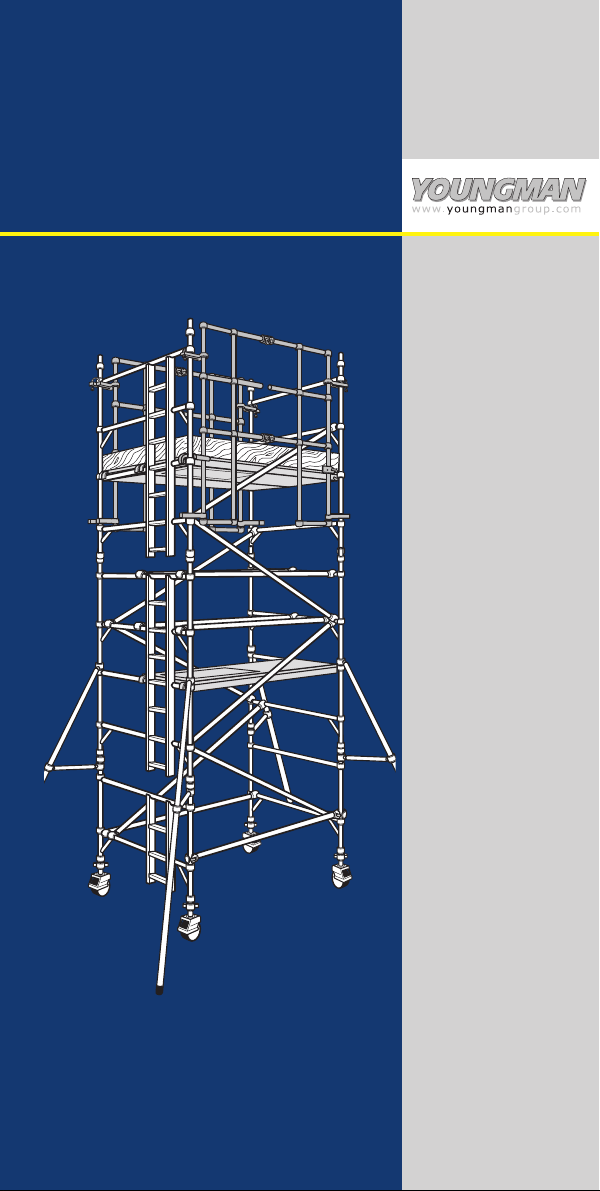
BOSS MOBILE
ALUMINIUM TOWER
1450/850 LADDERSPAN
USER GUIDE
December 2005
3T - THROUGH THE TRAPDOOR
METHOD AND BOSS ADVANCED
GUARDRAIL SYSTEM
Page 2

BOSS 1450/850 Ladderspan User Guide
Introduction
Please read this guide carefully.
BOSS mobile aluminium towers are light-weight scaffold towers
used throughout the building and construction industry for both
indoor and outdoor access solutions where a stable and secure
platform is required. Ideal for maintenance and installation work
or short-term access, the highly versatile towers provide a strong
working platform for a variety of heights.
This User Guide provides you with step by step instructions to
ensure your system is erected easily and safely, using the 3T
(Through The Trapdoor) method or the BOSS Advanced
Guardrail System.
The law requires that personnel erecting towers must be
competent and qualified to do so. Any person erecting an
Youngman BOSS mobile tower should have a copy of this guide.
For full information on the use of mobile access and working
towers consult the PASMA guide or EN1298.
If you need further information, design advice, additional guides
or any other help with this product, please contact Youngman on
08700 130360 or email
youngmansales@youngmangroup.com
Compliances
The BOSS aluminium system has been tested and certified to BS
1139: Part 3: 1994 (HD1004) and DIN 4422 8/92, as well as
receiving national approvals in Switzerland, Sweden, Norway
and the Czech Republic. It also confirms to US standard ANSI
1988.
Preparation and Inspection
Inspect the equipment before use to ensure that it is not damaged
and that it functions properly.
Safety
Refer to Usage Advice.
1
BS1139:PART 3:1994
C
E
R
T
I
F
I
E
D
T
O
B
R
I
T
S
H
S
T
A
N
D
A
R
D
S
DIN 4422 8/92:
HD 1004-3 8/12
Page 3
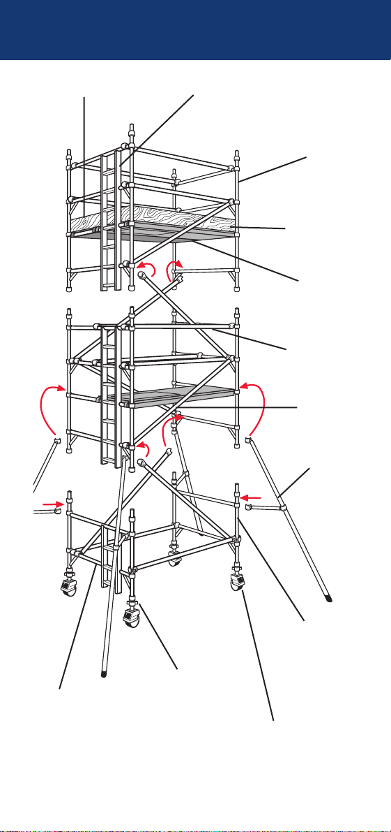
Components - 3T Method
2
End Toeboards
4 Rung Ladder Frame
Toeboards
Platform
(Fixed and Trap
Door Decks)
Horizontal
Brace
Diagonal
Brace
2 Rung
Span
Frame
Stabiliser
Castor
Adjustable leg
2 Rung
Ladder
Frame
4 Rung
Span
Frame
Page 4
3
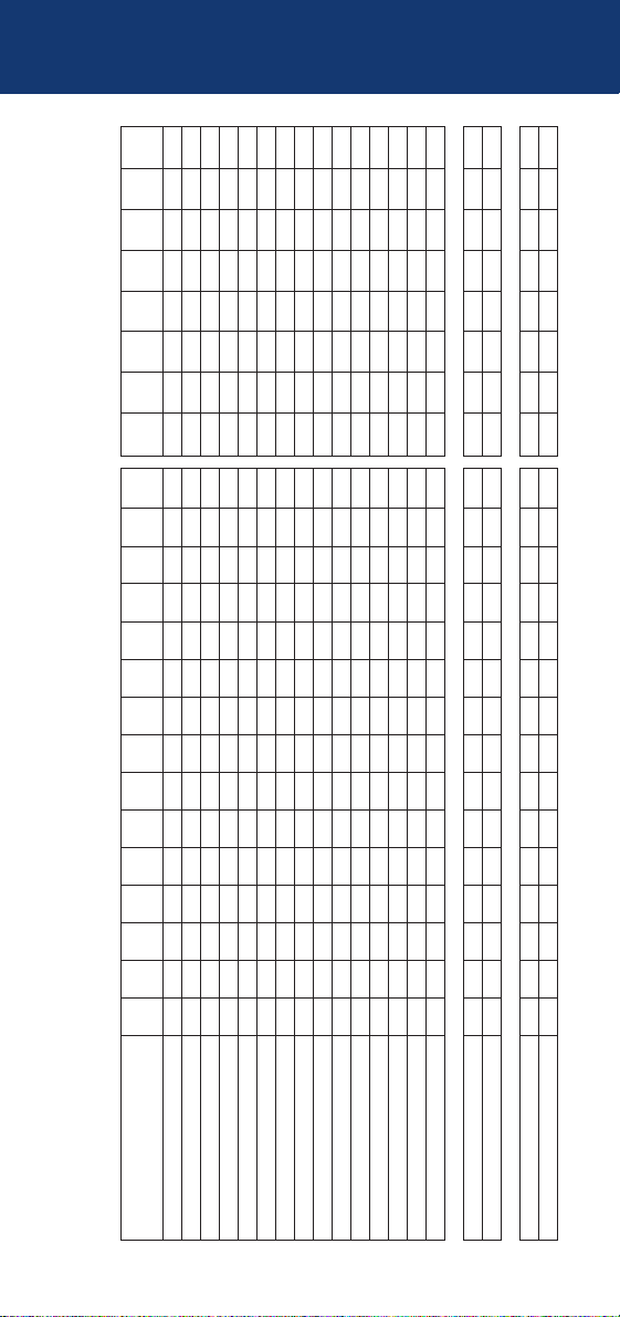
BOSS 1450 Ladderspan to HD1004: Available in 2 lengths - 1.8m and 2.5m
Internal/External Use
Description Working Height 3.2m 3.7m 4.2m 4.7m 5.2m 5.7m 6.2m 6.7m 7.2m 7.7m 8.2m 8.7m 9.2m 9.7m 10.2m
Platform Height 1.2m 1.7m 2.2m 2.7m 3.2m 3.7m 4.2m 4.7m 5.2m 5.7m 6.2m 6.7m 7.2m 7.7m 8.2m
125/150/200mm Castor 4 4 4 4 4444444444 4
250mm Adjustable Leg 4 4 4 4 4444444444 4
1450 2 Rung Ladder Frame 1 1 1 1 1 1 1 1
1450 2 Rung Span Frame 1 1 1 1 1 1 1 1
1450 3 Rung Ladder Frame 1 1 11111
1450 3 Rung Span Frame 1 1 11111
1450 4 Rung Ladder Frame 1 1 1 2122323343 4
1450 4 Rung Span Frame 1 1 1 2122323343 4
1.8m and 2.5m Fixed Deck 1 1 1 2 1112111211 1
1.8m and 2.5m Trap Door Deck 1 1 1 1 2222333344 4
1.8m and 2.5m Horizontal Brace (red) 6 6 6 6 10 10 10 10 14 14 14 14 18 18 18
2.1m and 2.7m Diagonal Brace (blue) 2 3 3 4 56789101112131415
1.8m and 2.5m Side Toeboard 2 2 2 2 2222222222 2
1.2m End Toeboard 2 2 2 2 2222222222 2
Toeboard Holder 4 4 4 4 4444444444 4
SP7 Fixed stabiliser 4 4444444
SP10 Telescopic Stabiliser 444 4
Total Tower self-weight (kgs) 1.8m 91 99 103 146 161 169 175 195 210 217 224 257 272 279 286
Total Tower self-weight (kgs) 2.5m 108 116 120 169 185 194 201 226 243 251 258 296 313 321 328
Internal Use only
10.7m 11.2m 11.7m 12.2m 12.7m 13.2m 13.7m 14.2m
8.7m 9.2m 9.7m 10.2m 10.7m 11.2m 11.7m 12.2m
44444444
44444444
11 11
11 11
1111
1111
45455656
45455656
21112111
45555666
18 22 22 22 22 26 26 26
16 17 18 19 20 21 22 23
22222222
22222222
44444444
44444444
306 320 328 334 354 369 377 383
354 370 378 385 411 427 436 443
Quantity Schedule - 1450 3T Method
Page 5

Quantity Schedule - 1450 3T Method
4
Number of working platforms allowed
The MAXIMUM SAFE WORKING LOAD (the combined weight of the users, tools
and materials) that may be placed on the tower is the total weight less the self
weight of the tower. The total weight for the towers shown in the schedule is 950kg.
Example 1:
A 1450 tower built using the 3T method with a 4.2m platform height and a
platform length of 1.8m has a self weight of 175kg.
950kg — 175kg = 775kg maximum safe working load
total weight self weight (users, tools and materials)
Example 2:
A 1450 tower built using the 3T method with a 11.7m platform height and a
platform length of 2.5m has a self weight of 436kg.
950kg — 436kg = 514kg maximum safe working load
total weight self weight (users, tools and materials)
For greater heights and loads, consult Youngman for guidance.
Platform Loading
On a 1450 tower a platform may comprise of a single deck or two decks placed
side by side. The maximimum safe working load (the combined weight of the
users, tools and materials) that may be placed on a platform is 275kg. This must
be evenly distributed over either one deck, or two decks placed side by side.
The quantities on page 3 will enable BOSS towers to be built safely and therefore
comply with the requirements of the Work at Height Regulations 2005. They include
double guardrails to all platforms, and toeboards will need to be added if any levels
are used as working platforms and for storage of materials. BS1139 requires
platforms at least every 4m, and these measures will exceed that requirement.
Ballast: Internal/External use
There is no requirement for ballast on 1450 towers if using stabilisers as
detailed in the table on page 3.
Mobile Outriggers
MP7 mobile outriggers can be used instead of SP7 and SP10 stabilisers,
as detailed below. MP7 mobile outrigger kits comprise:
MP7 MOBILE OUTRIGGER 4
125/150/200mm CASTOR 4
(Use same diameter castors as on tower)
250mm ADJUSTABLE LEG 4
PLAN BRACES 4
The above components replace:
SP7/SP10 STABILISER 4
Stabilisers
To improve rigidity, larger stabilisers can be used at a lower level than
shown in the table.
Page 6
5
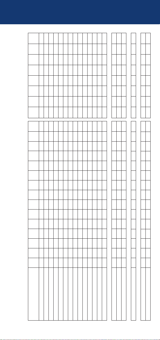
BOSS 850 Ladderspan to HD1004: Available in 2 lengths - 1.8m and 2.5m
Internal/External Use
Description Working Height 3.2m 3.7m 4.2m 4.7m 5.2m 5.7m 6.2m 6.7m 7.2m 7.7m 8.2m 8.7m 9.2m 9.7m 10.2m
Platform Height 1.2m 1.7m 2.2m 2.7m 3.2m 3.7m 4.2m 4.7m 5.2m 5.7m 6.2m 6.7m 7.2m 7.7m 8.2m
125/150/200mm Castor 4 4 4 4 4444444444 4
250mm Adjustable Leg 4 4 4 4 4444444444 4
850 2 Rung Ladder Frame 1 1 1 1 1 1 1 1
850 2 Rung Span Frame 1 1 1 1 1 1 1 1
850 3 Rung Ladder Frame 1 1 11111
850 3 Rung Span Frame 1 1 11111
850 4 Rung Ladder Frame 1 1 1 2122323343 4
850 4 Rung Span Frame 1 1 1 2122323343 4
1.8m and 2.5m Trap Door Deck 1 1 1 2 2223333444 4
1.8m and 2.5m Horizontal Brace (red) 6 6 6 6 10 10 10 10 14 14 14 14 18 18 18
2.1m and 2.7m Diagonal Brace (blue) 2 3 3 4 56789101112131415
1.8m and 2.5m Side Toeboard 2 2 2 2 2222222222 2
0.6m End Toeboard 2 2 2 2 2222222222 2
Toeboard Holder 4 4 4 4 4444444444 4
SP7 Fixed stabiliser 4 4 4 4 4
SP10 Telescopic Stabiliser 4444
SP15 Telescopic Stabiliser 444 4
Ballast required (kgs) 2.5m 25 50 75
Total Tower self-weight (kgs) 1.8m 72 79 106 126 139 146 151 185 198 204 210 245 258 265 270
Total Tower self-weight (kgs) 2.5m 84 90 117 143 158 165 172 210 251 283 314 279 294 301 307
Internal Use only
10.7m 11.2m 11.7m 12.2m 12.7m 13.2m 13.7m 14.2m
8.7m 9.2m 9.7m 10.2m 10.7m 11.2m 11.7m 12.2m
44444444
44444444
11 11
11 11
1111
1111
45455656
45455656
55556666
18 22 22 22 22 26 26 26
16 17 18 19 20 21 22 23
22222222
22222222
44444444
444
44444
276 289 296 316 336 349 356 362
318 334 341 362 387 403 410 416
Quantity Schedule - 850 3T Method
Page 7

Quantity Schedule - 850 3T Method
6
Number of working platforms allowed
The MAXIMUM SAFE WORKING LOAD (the combined weight of the users, tools
and materials) that may be placed on the tower is the total weight less the self
weight of the tower. The total weight for the towers shown in the schedule is 950kg
.
Example 1:
An 850 tower built using the 3T method with a 4.2m platform height and a
platform length of 1.8m has a self weight of 151kg.
950kg — 151kg = 799kg maximum safe working load
total weight self weight (users, tools and materials)
Example 2:
An 850 tower built using the 3T method with a 11.7m platform height and a
platform length of 2.5m has a self weight of 410kg.
950kg — 410kg = 540kg maximum safe working load
total weight self weight (users, tools and materials)
For greater heights and loads, consult Youngman for guidance.
Platform Loading
On an 850 tower a platform comprises a single deck. The maximimum safe
working load (the combined weight of the users, tools and materials) that may be
placed on a platform is 275kg, evenly distributed over the deck.
The quantities on page 5 will enable BOSS towers to be built safely and therefore
comply with the requirements of the Work at Height Regulations 2005. They include
double guardrails to all platforms, and toeboards will need to be added if any levels
are used as working platforms and for storage of materials. BS1139 requires
platforms at least every 4m, and these measures will exceed that requirement.
Ballast: Internal/External use
Stabiliser requirements are based on calculations from BS1139:
1. Up to 8.2m (platform height) the stabilisers and ballast are shown for
external use. 2. Above 8.2m the shedule is for internal use only.
For internal use only towers may be erected up to 12.2m without ballast.
SP10 stabilisers may be fitted up to 9.7m platform height. For greater
rigidity, fit SP15 stabilisers at lower height.
Mobile Outriggers
MP7 and MP16 mobile outriggers can be used instead of SP10 and SP15 telescopic
stabilisers respectively, as detailed below. MP7 mobile outrigger kits comprise:
MP7 MOBILE OUTRIGGER 4
125/150/200mm CASTOR 4
(Use same diameter castors as on tower)
250mm ADJUSTABLE LEG 4
PLAN BRACES 4
The above components replace:
SP10/SP15 STABILISER 4
Page 8
7
Internal/External Use
Description Working Height 3.2m 3.7m 4.2m 4.7m 5.2m 5.7m 6.2m 6.7m 7.2m 7.7m 8.2m 8.7m 9.2m 9.7m 10.2m
Platform Height 1.2m 1.7m 2.2m 2.7m 3.2m 3.7m 4.2m 4.7m 5.2m 5.7m 6.2m 6.7m 7.2m 7.7m 8.2m
125/150/200mm Castor 4 4 4 4 4444444444 4
250mm Adjustable Leg 4 4 4 4 4444444444 4
1450 2 Rung Ladder Frame 1 1 1 1 1 1 1 1
1450 2 Rung Span Frame 1 1 1 1 1 1 1 1
1450 3 Rung Ladder Frame 1 1 11111
1450 3 Rung Span Frame 1 1 11111
1450 4 Rung Ladder Frame 1 1 1 2122323343 4
1450 4 Rung Span Frame 1 1 1 2122323343 4
1.8m and 2.5m Advanced Guardrail 2 2 2 2 2222222222 2
1.8m and 2.5m Fixed Deck 1 1 2 2 2222223333 4
1.8m and 2.5m Trap Door Deck 1 1 1 1 2222223333 4
1.8m and 2.5m Horizontal Brace (red) 2 2 2 2 6 6 6 10 10 10 10 10 14 14 14
2.1m and 2.7m Diagonal Brace (blue) 2 3 3 4 56789101112131415
1.8m and 2.5m Side Toeboard 2 2 2 2 2222222222 2
1.2m End Toeboard 2 2 2 2 2222222222 2
Toeboard Holder 4 4 4 4 4444444444 4
SP7 Fixed stabiliser 4 4444444
SP10 Telescopic Stabiliser 444 4
Total Tower self-weight (kgs) 1.8m 107 114 132 162 190 198 204 218 224 232 266 286 300 307 342
Total Tower self-weight (kgs) 2.5m 125 133 156 186 221 229 236 252 259 267 312 332 348 357 402
Internal Use only
10.7m 11.2m 11.7m 12.2m 12.7m 13.2m 13.7m 14.2m
8.7m 9.2m 9.7m 10.2m 10.7m 11.2m 11.7m 12.2m
44444444
44444444
11 11
11 11
1111
1111
45455656
45455656
22222222
45555666
45555666
14 18 18 18 18 22 22 22
16 17 18 19 20 21 22 23
22222222
22222222
44444444
44444444
348 390 398 404 410 452 460 467
408 463 471 478 484 539 547 554
BOSS 1450 Ladderspan to HD1004: Advanced Guardrail System - Available in 2 lengths, 1.8m and 2.5m
IMPORTANT! For other Quantity Schedule information refer to Page 4 -1450 3T Method
Quantity Schedule - 1450 Advanced
Guardrail System
Page 9

8
Quantity Schedule - 850 Advanced
Guardrail System
Internal/External Use
Description Working Height 3.2m 3.7m 4.2m 4.7m 5.2m 5.7m 6.2m 6.7m 7.2m 7.7m 8.2m 8.7m 9.2m 9.7m 10.2m
Platform Height 1.2m 1.7m 2.2m 2.7m 3.2m 3.7m 4.2m 4.7m 5.2m 5.7m 6.2m 6.7m 7.2m 7.7m 8.2m
125/150/200mm Castor 4 4 4 4 4444444444 4
250mm Adjustable Leg 4 4 4 4 4444444444 4
850 2 Rung Ladder Frame 1 1 1 1 1 1 1 1
850 2 Rung Span Frame 1 1 1 1 1 1 1 1
850 3 Rung Ladder Frame 1 1 11111
850 3 Rung Span Frame 1 1 11111
850 4 Rung Ladder Frame 1 1 1 2122323343 4
850 4 Rung Span Frame 1 1 1 2122323343 4
1.8m and 2.5m Advanced Guardrail 2 2 2 2 2222222222 2
1.8m and 2.5m Trap Door Deck 1 1 1 1 2222223444 4
1.8m and 2.5m Horizontal Brace (red) 2 2 2 2 666610101010141414
2.1m and 2.7m Diagonal Brace (blue) 2 3 3 4 56789101112131415
1.8m and 2.5m Side Toeboard 2 2 2 2 2222222222 2
0.6m Toeboard 2 2 2 2 2222222222 2
Toeboard Holder 4 4 4 4 4444444444 4
SP7 Fixed stabiliser 4 4 4 4 4
SP10 Telescopic Stabiliser 4444
SP15 Telescopic Stabiliser 444 4
Ballast required (kgs) 2.5m 25 50 75
Total Tower self-weight (kgs) 1.8m 88 94 121 127 154 161 167 186 199 205 226 260 273 280 286
Total Tower self-weight (kgs) 2.5m 100 107 134 140 175 182 189 208 248 280 331 296 311 318 324
Internal Use only
10.7m 11.2m 11.7m 12.2m 12.7m 13.2m 13.7m 14.2m
8.7m 9.2m 9.7m 10.2m 10.7m 11.2m 11.7m 12.2m
44444444
44444444
11 11
11 11
1111
1111
45455656
45455656
22222222
55556666
14 18 18 18 18 22 22 22
16 17 18 19 20 21 22 23
22222222
22222222
44444444
444
44444
291 305 311 331 351 365 371 377
335 351 358 379 404 420 427 433
BOSS 850 Ladderspan to HD1004: Advanced Guardrail System - Available in 2 lengths, 1.8m and 2.5m
IMPORTANT! For other Quantity Schedule information refer to page 6 - 850 3T method
Page 10

Erection
● Check that all components are on site and that they are
functioning correctly – See Quantity Schedule.
● Check if the ground on which the mobile access tower is to be
erected and moved is capable of supporting the tower.
● The safe working load is 275kgs (606Ibs), per platform unit,
uniformly distributed up to a maximum of 950kgs (2100Ibs)
per tower (including self weight).
● Towers must always be climbed from the inside during
assembly using the built-in ladder provided.
● Adjustable legs should only be used for levelling.
Lifting of equipment
● Tower components should be firmly
secured by a reliable lifting material
(e.g. rope), employing a reliable knot
(e.g. clove hitch), to ensure safe
fastening.
Stabilisers/Ballast
● Stabilisers or outriggers and ballast weights should always be
fitted when specified.
● Ballast is used at the base to stabilise towers against
overturning. The Quantity Schedule shows the recommended
stabilisation. In circumstances where there is restricted ground
clearance for stabilisers/outriggers, contact your supplier for
advice. It must be of solid materials (i.e. not water or loose
sand) and should not be positioned to overload individual
legs. Ballast should be secured against accidental removal
where practicable, and be supported on the lowest rung of the
bottom frame.
Movement
● The tower should only be moved by manual effort, and only
from the base.
● When moving the tower, beware of live electrical apparatus,
particularly overhead, plus wires or moving parts of machinery.
● No personnel or materials should be on the tower during movement.
● Caution should be exercised when wheeling a tower over
rough, uneven or sloping ground, taking care to unlock and
lock castors. If stabilisers are fitted, they should only be lifted
sufficiently above the ground to clear ground obstructions.
● The height of the tower, when being moved, should not
exceed 2.5 times the minimum base dimensions, or 6 metres
overall height.
Usage Advice
9
Attachment
via location
hole on
platform.
Page 11

During Use
● Beware of high winds in exposed, gusty or medium breeze conditions.
We recommend that in wind speeds over 7.7 metres per second (17
m.p.h.), cease working on the tower. If the wind becomes a strong
breeze, expected to reach 11.3 metres per second (25 m.p.h.), tie the
tower to a rigid structure. If the wind is likely to reach gale force, over
18 metres per second (40 m.p.h.), the tower should be dismantled.
Wind Beaufort Beaufort Speed in Speed in
Description Scale No. m.p.h. m/sec.
Medium Breeze Raises dust and loose 4 8-12 4-6
paper, twigs snap off.
Strong Breeze Large branches in motion, 6 25-31 11-14
telegraph wires whistle.
Gale Force Walking is difficult. 8 39-46 17-21
Beware of open ended buildings which can cause funneling effect.
● Do not abuse equipment. Damaged or incorrect components
should never be used.
● Raising and lowering components, tools, and/or materials by
rope should be conducted within the tower base. Ensure that
the safe working load of the supporting decks and the tower
structure is not exceeded.
● The assembled tower is a working platform and should not be
used as a means of access to other structures.
● Beware of horizontal forces (e.g. power tools) which could
generate instability. Maximum horizontal force 20kg.
● The stairway towers featuring an inclined staircase access are for
use with personnel frequently carrying tools and/or materials.
● Mobile towers are not designed to be suspended - please
refer to your supplier for advice.
Ties
● Ties should be used when the tower goes beyond its safe height
beyond the limits of the stabilisers/outriggers or if there is a
danger of instability. They should be rigid, two way ties fastened
to both uprights of the frame with load-bearing right angled or
swivel couplers. Only couplers suitable for the 50.8mm dia. tube
of the tower should be used. Ideally ties should secure to both
faces of a solid structure or by means of anchorages.
● The tie frequency may vary depending on the application, but
they should, at a minimum, be at every 4 metres height.
Maintenance
● All components and their parts should be regularly inspected to
identify damage, particularly to welds. Lost or broken parts should be
replaced, and any tubing with indentations greater than 5mm should
be put to one side for manufacture repair. Adjustable leg threads
should be cleaned and lightly lubricated to keep them free running.
Usage Advice
10
Page 12

THE 3T METHOD
When building a BOSS tower:
● To comply with the Work at Height Regulations we show
assembly procedures with platforms every 2 metres in height,
and, the locating of guardrails in advance of climbing onto a
platform to reduce the risk of a fall.
● All platforms feature double guardrails on both faces of either
individual platforms or fully decked levels.
● All guardrails should be 1 and 2 rungs (0.5m and 1.0m)
above platforms.
● Never stand on an unguarded platform positioned above the
first rung of a tower. If your risk assessment shows it
necessary you may also need to guardrail platforms at this
level.
● Always start building with the smallest height
frames at the base of the tower:
Platform Heights in Metres Frame
at Base
1.7 2.2 3.7 4.2 5.7 6.2 7.7 8.2 9.7 10.2 11.7 12.2
2 rung
2.7 4.7 6.7 8.7 10.7
3 rung
1.2 3.2 5.2 7.2 9.2 11.2
4 rung
Where all 3 frame heights are used in a tower, start with 2
rung frames at the base, with the 3 rung frames nexts and the
4 rung frames on the top.
Refer to the quantity schedules for detail.
To dismantle a BOSS tower:
● Remove toeboards, and pass down the tower.
● Unclip farthest end of braces and immediately go to protected
trapdoor position on ladder to complete removal.
● Remove upper platforms from protected platform levels below.
● Pass removed components out of the tower to a colleague.
11
Assembly and dismantling procedures
Page 13

ADVANCED GUARDRAIL SYSTEM
In addition to the 3T method, Youngman also recommends the
BOSS Advanced Guardrail System.
When building a BOSS tower with Advanced
Guardrail Frames:
● By using the BOSS Advanced Guardrail you will ensure
compliance with the Work at Height Regulations by providing a
guardrail in advance of climbing onto a platform. The BOSS
Advanced Guardrail System features guardrail protection that is
pre-set to the correct heights and dimensions.
● IMPORTANT! Always start building the tower with the smallest
frames at the base i.e. 2 rungs, and/or 3 rung frames followed by
4 rung frames. Refer to the quantity schedules for detail.
● Platforms are installed every 2 metres. On 1450 towers, each
platform level has 2 decks.
● When you reach the required working height, make sure you engage
the interlock clips on the Advanced Guardrail frames. Youngman
recommends that the Advanced Guardrail System is left in place on
the top platform until it is dismantled. This removes the need to fit 4
horizontal braces as guardrails on the top platform. However if you
wish to use the Advanced Guardrail System to build another tower
whilst leaving the first tower standing, you MUST fit an additional 4
horizontal braces to act as guardrails for the top platform.
● BEFORE moving the Advanced Guardrail frames upwards to
the next platform level you must install 2 horizontal braces on
both faces of the tower to act as guardrails
To dismantle a BOSS tower with Advanced Guardrail
Frames:
● If the Advanced Guardrail System has been removed to build
other towers it must be replaced at the highest platform before
dismantling commences.
● Climb to the highest platform. Remove toe boards and toe
board clips and disconnect diagonal braces. Remove horizontal
braces acting as guardrails.
IMPORTANT! The Advanced Guardrail frames MUST be in
position before you remove any horizontal braces.
● Climb down to the platform below. Move Advanced Guardrail
frames down to the platform you are now standing on.
● Remove the decks, end frames and diagonals, above the level
you are standing on.
● Dismantling then proceeds in the same sequence for the
remainder of the tower.
Assembly and dismantling procedures
12
Page 14

Ensure all brace claws operate and lock correctly
❏
prior to erection
Inspect components prior to erection
❏
Inspect tower prior to use
❏
Tower upright and level
❏
Castors locked/legs correctly adjusted
❏
Diagonal braces fitted
❏
Stabilisers/outriggers fitted as specified
❏
Platforms located and windlocks on
❏
Toeboards located
❏
Check guardrails are fitted correctly. See illustration below.
❏
REFER TO THIS CHECKLIST BEFORE USING EACH TIME.
Checklist
13
ENSURE HORIZONTAL BRACES/GUARDRAILS ARE FITTED
CORRECTLY.
ALWAYS FIT AS SHOWN.
Page 15

Always start building with the smallest height
frames at the base of the tower:
Platform Heights in Metres Frame
at Base
1.7 2.2 3.7 4.2 5.7 6.2 7.7 8.2 9.7 10.2 11.7 12.2
2 rung
2.7 4.7 6.7 8.7 10.7
3 rung
1.2 3.2 5.2 7.2 9.2 11.2
4 rung
Where all 3 frame heights are used in a tower, start with 2 rung
frames at the base, with the 3 rung frames next and the 4 rung
frames on the top. Refer to the quantity schedules for detail. The
procedure illustrated shows a tower starting with a 2 rung frame.
Youngman recommend two persons are used to build
BOSS towers. Above 4m height it is essential that at
least two persons are used. Only climb the tower from
the inside.
1 Push castor onto adjustable
leg. Insert adjustable
leg/castor assemblies into 2
rung span frame. Lock
castors. Repeat with ladder
frame. Base plates can be
fitted to adjustable legs if it is not necessary to move the tower.
2 Fit a horizontal brace (red) onto the vertical of the span frame,
facing claws outwards. The frame will now be self-supporting.
Note: All locking claws must be opened before fitting.
3 Position ladder frame as shown.
Fit the other end of the horizontal
brace onto the ladder frame
vertical. Fit another horizontal
brace between the rungs of both
frames to square the tower.
Assembly Procedure 1450 Tower - 3T
14
Unlocked
Locked
Page 16

4 Fit 2 additional end frames and check the frame interlock clips
are engaged. Fit 2 diagonals, in opposing directions, between
the 1stand 3rdrungs. Ensure the frames are vertical and level by
checking with a spirit level and setting the adjustable legs as
required. Fit stabilisers (see notes on page 30).
5 Fit a fixed deck on lowest rung. Fit a trapdoor deck on 4th
rung (2.0m) with the trapdoor next to the ladder.
Climb ladder and, from a protected trapdoor position, fit
guardrails on 5thand 6thrungs, in that order, on both sides of
the platform.
Do not climb onto the platform until fully
guardrailed.
Guardrails should be 0.5m and 1.0m (1 and 2 rungs) above
platform in all cases.
Assembly Procedure 1450 Tower - 3T
15
INTERLOCK CLIP
Locked
Unlocked
Page 17

6 Fit the next pair of diagonal braces in opposing directions
between the 3rdand 5thrungs. Add 2 additional end frames.
7 If finishing at this height, (4.2m platform), the fixed deck
should first be repositioned to the 8thrung of the tower. Fit a
trapdoor deck alongside it, with the trapdoor next to the
ladder.
Climb ladder and, from a protected trapdoor position, fix
guardrails on 9
th
and 10thrungs, in that order, on both sides
of the tower. Add a diagonal brace.
Assembly Procedure 1450 Tower - 3T
16
Page 18

8 When building beyond a 4.2m platform height.
Continue to add end frames, diagonals and trapdoor
platforms as shown in the previous steps. Add guardrails at
0.5m and 1.0m (in that order) above the platform from the
protected trapdoor position. Do not climb onto the
platform until it is fully guardrailed.
Continue until the required height is reached. Reposition the
fixed deck to the required platform height and fit a trapdoor
deck alongside it as shown in stage 7. Fit the final guardrails
as shown in stage 7.
Assembly Procedure 1450 Tower - 3T
17
Page 19

9 Fit toeboards (see instructions on page 29).
The tower is now complete.
Assembly Procedure 1450 Tower - 3T
18
Page 20

Always start building with the smallest height
frames at the base of the tower:
Platform Heights in Metres Frame
at Base
1.7 2.2 3.7 4.2 5.7 6.2 7.7 8.2 9.7 10.2 11.7 12.2
2 rung
2.7 4.7 6.7 8.7 10.7
3 rung
1.2 3.2 5.2 7.2 9.2 11.2
4 rung
Where all 3 frame heights are used in a tower, start with 2 rung
frames at the base, with the 3 rung frames next and the 4 rung
frames on the top. Refer to the quantity schedules for detail. The
procedure illustrated shows a tower starting with a 4 rung frame.
1 Insert adjustable leg/castor assemblies into end frames and lock
the castors (see diagram page 14, step 1). Base plates can be
fitted to the adjustable legs if it is not necessary to move the tower.
Fit 2 horizontal braces to the 850 end frames as shown in steps 2
and 3 for the 1450 tower procedure (page 14).
Ensure the frames are vertical and level by checking with a
spirit level and setting the adjustable legs required.
2 Fit a deck on the 2
nd
rung with the trapdoor next to the ladder.
Fix guardrails on the 4thand 5thrungs on both sides of the
tower.
3 Fit 2 diagonal braces in opposing directions between the 1st
and 3
rd
rungs. Ensure the frames are vertical and level by
checking with a spirit level and setting the adjustable legs as
necessary.
Assembly Procedure 850 Tower - 3T
19
Page 21

Fit the next pair of end frames and check the frame interlock
clips are engaged. Fit stabilisers (see notes on page 30).
4 Fit 2 pairs of diagonal braces in oposing directions between
the 3
rd
and 5thrungs and the 5thand 7thrungs. Locate a
trapdoor deck on the 6thrung with the trapdoor next to the
ladder.
5 Climb the ladder and from the protected position of the
trapdoor, fit guardrails to the 7
th
and 8thrungs (in that order),
on both sides of the tower.
Assembly Procedure 850 Tower - 3T
20
INTERLOCK CLIP
Locked
Unlocked
Page 22

6 Continue the procedure until the required working height is
reached, adding additional end frames, diagonal braces
and platforms. Always add horizontal guardrails from the
protected position within the trapdoor, (as shown in step 5).
Fit the toeboards (see instruction on page 29).
The tower is now complete.
Assembly Procedure 850 Tower - 3T
21
Page 23

The BOSS Advanced Guardrail is available for 1.8m or 2.5m
platform lengths as required.
Two Advanced Guardrail frames are required to
build a tower.
Identification
A Locking Hinge Joints
B Locking Claw
C Windlatch
D Interlock Clips
E U-Brackets
Always start building with the smallest height
frames at the base of the tower.
Platform Heights in Metres Frame at Base
1.7 2.2 3.7 4.2 5.7 6.2 7.7 8.2 9.7 10.2 11.7 12.2 2 rung
2.7 4.7 6.7 8.7 10.7 3 rung
1.2 3.2 5.2 7.2 9.2 11.2 4 rung
Assembly Procedure - Advanced Guardrail
22
Where all 3 frame heights are used in a tower, start with 2 rung
frames at the base, with the 3 rung frames next and the 4 rung
frames on top. Refer to the quantity shedules for details.
The procedure illustrated shows a tower starting with a 2 rung
frame. The method is the same for both 1450 and 850 towers.
A
A
E
C
E
D
E
E
B
D
Page 24

Assembly
1 Insert adjustable leg/castor assemblies into end frames and lock
the castors (see diagram page 14, step 1). Base plates can be
fitted to the adjustable legs if it is not necessary to move the
tower. Fit 2 horizontal braces to the end frames as shown in
steps 2 and 3 for the 1450 tower procedure (page 14).
2 Add the next pair of end frames and check the frame
interlock clips are engaged. Fit 2 diagonal braces between the
1
st
and 3rdrungs of the tower. Ensure the frames are vertical
and level by checking with a spirit level and setting adjustable
legs as required. Fit stabilisers (see notes on page 30). Fit
another diagonal between the 3rdand 5thrungs.
On 1450 towers fit a fixed and a trapdoor deck on the 4thrungs
of the tower with the trapdoor next to the ladder. On 850 towers
insert a trapdoor deck with the trapdoor next to the ladder.
Never climb onto the platform until the Advanced
Guardrails are in position on both sides of the tower
with the locking claws and windlatches engaged.
3 Unfold the advanced guardrails,
making sure both locking hinge joints
(A) are locked in the open position with
the operating trigger in the out position.
4 Open the locking claw (B) and check the windlatch (C) and
the interlock clips (D) are also in the open position.
Assembly Procedure - Advanced Guardrail
23
A
BCD
INTERLOCK CLIP
Locked
Unlocked
Page 25

5 Hold the guardrail with the locking claw (B) on your left hand
side. Lift the guardrail by holding the two middle vertical
frame tubes and raise it until the windlatch plate (C) and
locking claw (B) are level with the horizontal rungs of the end
frames, at the platform level (4thrung).
Move the guardrail to the right to fully engage the right hand
U-brackets (E) onto the vertical of the right hand end frame,
with the windlatch plate resting on the horizontal rung at the
platform level.
Move the left hand side of
the guardrail inwards.
Move the frame to the left to
engage the left hand Ubrackets (E) with the vertical
of the left hand end frames.
Position the locking claw (B)
over the rung of the left hand
end frame at the platform
level (4
th
rung) and pull
downwards to lock the claw.
Engage the windlatch (C)
over the rung of the right end
hand frame.
6 Repeat this procedure to fit
the second guardrail on the other face of the tower.
Assembly Procedure - Advanced Guardrail
24
B
C
Page 26

7 If the tower is to be used at this height (2.2m platform height)
climb the ladder to the platform.
IMPORTANT! Engage interlock clips (D), on the top
U-brackets, at both ends of each guardrail frame. Fit the
toeboard clips and add toeboards (see page 29).
The tower is now complete for the 2.2m platform height.
Assembly Procedure - Advanced Guardrail
25
8 When building a tower higher than a 2.2m platform tower,
omit step 7 and proceed as follows from step 6.
Fit a fourth diagonal brace, in the opposite direction, on the
other side of the tower, between the 3
rd
and 5thrungs. Climb
the ladder to the platform and fit 2 horizontal braces on each
side of the tower, on the 5thand 6thrungs (0.5m and 1.0m)
above the platform. These braces will become the platform
guardrails
when the
advanced
guardrail is
moved up the
tower. Add an
additional end
frame at each
end of the
tower and
engage the
frame interlock
clips.
x2
each
frame
D
Page 27

9 Fit the next pair of diagonal braces. Fit a fixed and a
trapdoor deck on 4 rungs (2m) above the platform level. On
850 width towers insert a trapdoor deck.
10 To advance the guardrail frame,
open the locking claw (B) and
unlock the windlatch (C).
Lift the guardrail frame up and move
it sideways to disengage the Ubrackets (E) at the locking claw (B)
end of the frame. Move the locking
claw (B) end of the guardrail frame
outwards and then move the frame sideways to disengage the Ubrackets (E) at the windlatch (C) end of the frame.
Raise the guardrail frame, holding the two middle vertical
tubes, until the windlatch plate (C) and locking claw (B) are
level with the horizontal rungs of the end frames, at the
platform level above your head.
Move the guardrail frame sideways to fully engage the
U-brackets (E) at the windlatch (C) end of the frame onto the
vertical end of the frame, with the windlatch plate resting on
the horizontal rung at the platform level.
Move the locking claw (B) end of the guardrail frame
inwards and then move the frame sideways to engage the
U-brackets (E) onto the vertical of the end frame.
Position the
locking claw (B)
over the rung of
the end frame
and pull
downwards to
lock the claw.
Lock the
windlatch (C).
Assembly Procedure - Advanced Guardrail
26
B
B
C
Page 28

11 Repeat this procedure to advance the second guardrail on
the other face of the tower.
12 Continue to construct the tower and advance the guardrail
by repeating steps 8 to 11 until the required height is
reached.
IMPORTANT! Engage interlock clips (D) on the
top U-brackets (E) at both ends of each
advanced guardrail frame.
13 Finally fit the toe board clips and toe boards. The tower is
now complete.
Assembly Procedure - Advanced Guardrail
27
x2
each
frame
D
E
Page 29

1 To dismantle a BOSS Tower with BOSS Advanced Guardrail
frames is the reverse of the assembly sequence.
However, if the Advanced Guardrail System has been
removed to build other towers, it must be replaced at the
highest platform before dismantling commences.
2 Climb to the highest platform.
3 Remove toe boards and toe boards clips and disconnect
diagonal braces. Remove horizontal braces acting as
guardrails.
IMPORTANT! The Advance Guardrail frames MUST
be in position before you remove any horizontal
braces.
4 Climb down to the platform below. Move the advanced
Guardrail frames down to the platform you are now standing
on. Remove the decks, end frames and diagonals, above the
level you are standing on.
5 Dismantling then proceeds in the same sequence for the
remainder of the tower.
Dismantling Procedure - Advanced Guardrail
28
Page 30

Fitting Toeboards
Lock yellow plastic toeboard clips over rung and deck claw as
shown. Position as (A) on right hand deck claw. On other side of
the working platform, position the clip as (B). Place 25mm thick
toeboards into slots in toeboard clips as shown.
Toeboards
29
Toeboard
Clip
Claw
Rung
Deck
A
B
Toeboard
Page 31

Stabilisers
Stabilisers are used when the tower is to be used occasionally,
frequent movement will require outriggers.
Attach one stabiliser to each corner of the tower at approx. 45
degrees. Secure top clamp below castings, bottom clamp as low
as possible. If clamp is obstructed, release and move. Ensure
clamps are rigidly fixed to limit movement.
With SP10 and SP15 stabilisers, extend telescopic leg until in
contact with ground.
When moving, check for obstructions and lock feet about 25mm
off the ground, unlock castors, and move. After moving, check all
castors are in ground contact and lock stabiliser feet.
Outriggers
For information on mobile outriggers please consult your
supplier.
Stability
30
SP10
SP15
250
2500
850
4914
1450
5688
SP7
250
1900
1227
250
850
2586
1450
3186
850
3939
1450
4671
Page 32

National Sales Office: T 08700 130 360
Email: youngmansales@youngmangroup.com
Head Office: Youngman Group, The Causeway, Maldon, Essex, CM9 4LJ
Ref. SD031 12-05
Youngman Group reserve the right to vary specifications listed here.
 Loading...