

Page 1
Service and
Maintenance
Manual
210 DUS JD4045
IT4 74HP
Air Compressor
This manual must be read carefully before using your Boss Industries, Inc. Air Compressor. Store in a safe and convenient location for future reference.
For technical support:
Phone: (800) 635-6587 (USA)
Phone: (219) 324-7776 (Outside USA)
Fax: (877) 254-4249 (USA)
Email: service@bossair.com
Website:
http://www.bossair.com
309416
05-03-2013 ARB
Page 2

01/31/2012
2 309416
Page 3

Contents
Manual Change History................................................................................................7
1.1 Revision List....................................................................................................7
Welcome........................................................................................................................8
2.1 General Information..........................................................................................8
2.2 Overview .........................................................................................................8
Safety...................................................................................................................9-13
3.1 General Safety Overview...................................................................................9
3.2 Safety Precautions..........................................................................................10
3.3 Safety and Information Decals..........................................................................12
Specifications..............................................................................................................14
4.1 Specification Sheet........................................................................................14
Description of Components..............................................................................15-18
5.1 Engine............................................................................................................15
5.2 Drive Coupling...............................................................................................15
5.3 Compressor Airend.......................................................................................15
5.4 Separator System..........................................................................................15
Separator Tank.........................................................................................15
Separator Element......................................................................................15
5.5 Pressure Relief Valve.....................................................................................16
5.6 Engine Air Filter..........................................................................................16
5.7 Compressor Air Filter.................................................................................16
5.8 Cooling Systems...........................................................................................16
Engine Radiator..........................................................................................16
Compressor Oil Cooler...............................................................................16
5.9 Compressor Oil Filter..................................................................................16
5.10 Compressor Oil Thermal Valve......................................................................16
5.11 Compressor Inlet Valve.................................................................................17
5.12 Minimum Pressure Valve...............................................................................17
5.13 Blowdown Valve..........................................................................................17
5.14 Blowdown Switch........................................................................................17
5.15 Discharge Pressure Regulator Valve...............................................................17
5.16 Instrument Panel...........................................................................................18
Engine Oil Pressure Gauge..........................................................................18
Engine Coolant Temperature Gauge............................................................18
Compressor Discharge Pressure Gauge......................................................18
Compressor Discharge Temperature Gauge................................................18
01/31/2012
3 309416
Page 4

Contents
Description of Components (continued)............................................................15-18
5.15 Instrument Panel (continued).....................................................................18
Hourmeter.......................................................................................18
Tachometer.........................................................................................18
Voltmeter.................................................................................18
Unloader Valve...........................................................................................18
Emergency Stop Switch.............................................................................18
Bypass Switch...........................................................................................18
Ignition Switch...........................................................................................18
Installation.............................................................................................19-23
6.1 System Installation Overview...........................................................................19
6.2 Placing the Machine........................................................................................19
6.3 Connecting the System Fuel Supply.................................................................19
6.4 Fuel Specifications..........................................................................................20
High Altitude and Low Temperature Fuel....................................................20
Cold Weather Fuel.....................................................................................20
6.5 Connecting the Air Discharge Lines...............................................................20
6.6 Pre-Startup Inspection .................................................................................20
6.7 Machine Documentation...............................................................................21
6.8 Check Fluid Levels.......................................................................................21
6.9 Initial Startup Preparation..............................................................................21
6.10 Initial Startup.................................................................................................22
Operation.............................................................................................................23-24
7.1 Routine Operating Procedures........................................................................23
Routine Startup Preparation........................................................................23
Routine Startup Procedure.........................................................................23
Routine Shutdown Procedure.....................................................................23
7.2 Emergency Shutdown Procedure..........................................................24
Maintenance........................................................................................................25-36
8.1 Maintenance Overview....................................................................................25
8.2 Maintenance Schedule....................................................................................25
8.3 Recommended Spare Parts List......................................................................26
8.4 Parts and Service Contact Information............................................................26
8.5 Maintenance Log............................................................................................27
01/31/2012
4 309416
Page 5

Contents
Maintenance (continued)....................................................................................25-36
8.6 Separator Element Replacement......................................................................28
8.7 Engine Air Filter Replacement..........................................................................29
8.8 Compressor Air Filter Replacement.................................................................30
8.9 Compressor Oil..............................................................................................31
Specifications.......................................................................................31
Adding Compressor Oil.............................................................................32
Changing Compressor Oil..........................................................................32
8.10 Compressor Oil Cooler.................................................................................33
8.11 Compressor Oil Filter....................................................................................33
8.12 Engine Cooling System Maintenance..............................................................34
Engine Coolant...........................................................................................34
Engine Radiator..........................................................................................34
Engine Fan.................................................................................................35
Engine Serpentine Belt...............................................................................35
8.13 Battery..........................................................................................................35
8.14 Standby Pressure Adjustment (For 100 PSI System).....................................35
8.15 Idle Speed Adjustment..................................................................................36
8.16 Rated Speed Adjustment...............................................................................36
Troubleshooting...................................................................................................37-40
9.1 Troubleshooting Chart....................................................................................37
9.2 Parts and Service Contact Information............................................................40
Warranty..............................................................................................................41-45
10.1 Warranty Policy............................................................................................41
10.2 Summary of Main Warranty Provisions..........................................................42
10.3 Warranty/Return Goods Instructions.............................................................43
10.4 Warranty Claims - Preparation of Part Return.................................................43
10.5 Return or Warranty Claims - Filing Procedures...............................................43
10.6 Warranty Claims Provisions..........................................................................44
10.7 Damage in Transit..........................................................................................44
10.8 Screw Compressor Airend Exchange Program..............................................45
Parts and Illustration Section...........................................................................46-63
11.1 Frame System...............................................................................................46
11.2 Engine System..............................................................................................48
11.3 Compressor System.....................................................................................50
11.4 Discharge System..........................................................................................52
01/31/2012
5 309416
Page 6

Contents
Parts and Illustration Section (continued)........................................................46-63
11.5 Cooling System..........................................................................................54
11.6 Electrical System.......................................................................................56
11.7 Canopy System.......................................................................................58
11.8 Decal System..............................................................................................60
11.9 Hose System......................................................................................62
11.10 System Wiring Diagram..............................................................................63
01/31/2012
6 309416
Page 7

Manual Change History
ETAD NOITACOL EGNAHCFONOITPIRCSED SLAITINI
1.1 Revision List
01/31/2012
7 309416
Page 8
Welcome
This manual must be read carefully before using your Boss Industries, Inc. Air Compressor. Store in a safe and convenient location for future reference.
For technical support:
Phone: (800) 635-6587 (USA)
Phone: (219) 324-7776 (Outside USA)
Fax: (877) 254-4249 (USA)
Email: service@bossair.com
Website:
http://www.bossair.com
Service and
Maintenance
Manual
210 DUS JD4045
IT4 74HP
Air Compressor
309416
01/31/2012
2.1 General Information
Thank you for choosing the 210 DUS Air Compressor. Before operating
this system, read over this manual and become well acquainted with your
new machine. Doing this will increase your safety and maximize the life
of the machine.
While this manual is written to be as accurate as possible, Boss Industries, Inc. strives to continually improve the efficiency and performance of
its machines. As a result, sometimes there may be slight differences
between a given version of the manual and the machine.
2.2 Overview
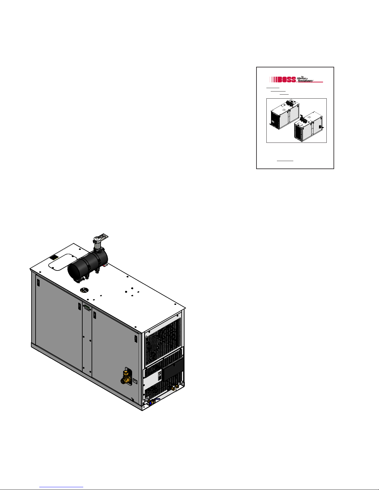
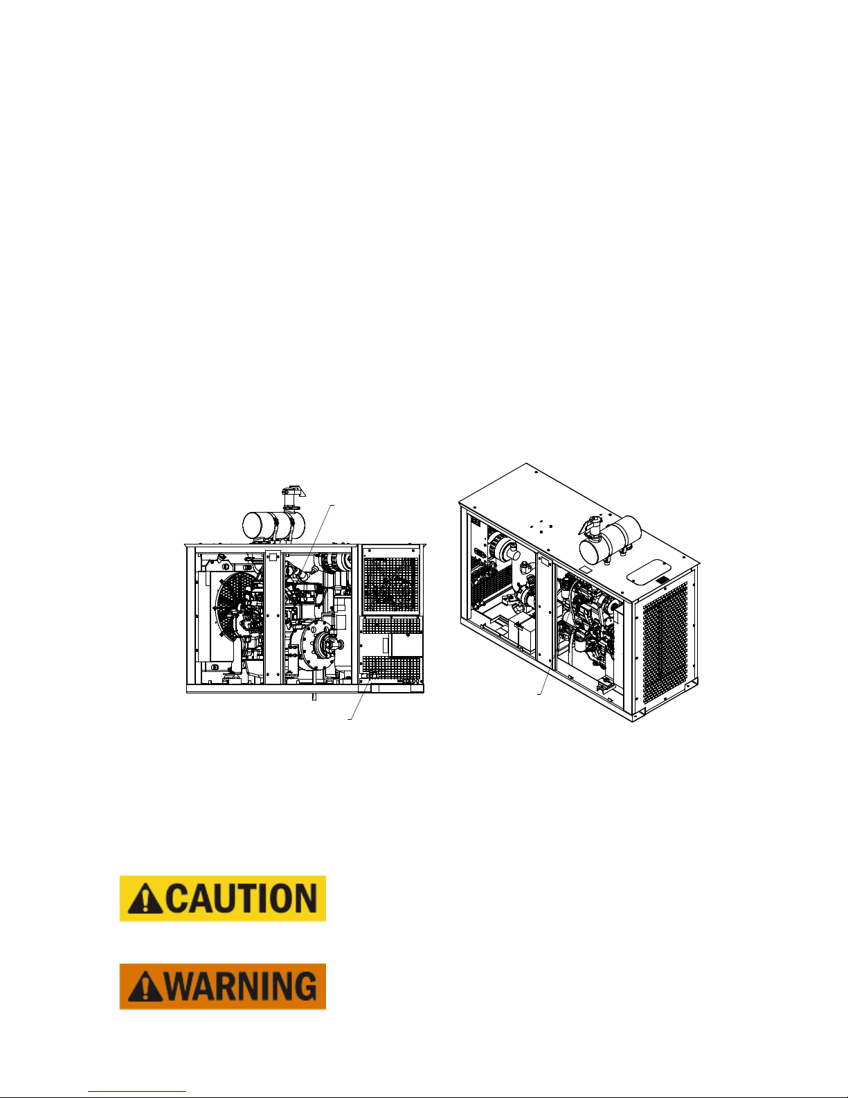
The 210 DUS Air Compressor is a compact, strategically designed system. It integrates all major
components on a single frame, which is enclosed in a tough, weather-resistant canopy.
The 210 DUS Air Compressor’s rotary screw
design guarantees continuous air output of up to
210 CFM (cubic feet per minute) at 100 PSI
(pounds per square inch). With remote fluid
drains and removable doors, virtually all
components are accessible for maintenance and
service. The instrument panel clearly displays
pressures, temperatures, and hours of operation.
Other features, including a spin-on compressor oil
filter and a drop-in separator element, reduce the
time and costs associated with routine
maintenance.
The 210 DUS Air Compressor also has enhanced
safety features to protect your valuable resources:
minimum pressure valve, high compressor oil
temperature shutdown, high discharge pressure
shutdown, automatic blowdown device, pressure
relief valve, high engine coolant temperature, low
engine oil pressure, and clearly displayed warning/
information decals.
01/31/2012
8 309416
Page 9
Safety
3.1 General Safety Overview
Remember, safety is basically common sense. While there are standard safety rules, each situation has
its own peculiarities that cannot always be covered by rules. Therefore with your experience and
common sense, you are in a position to ensure the safety of yourself and others. Lack of attention to
safety can result in: accidents, personal injury, reduction in efficiency, and worst of all – Loss of Life.
Watch for safety hazards and correct them promptly.
Understanding the proper operation of this equipment is critical to its safe operation. The owner, lessor,
and/or operator of this equipment is hereby notified and forewarned that any failure to observe the
safety and operating guidelines may result in injury and/or damage. Boss Industries, Inc. expressly
disclaims responsibility or liability for any injury or damage caused by failure to observe these specified
precautions or by failure to exercise the ordinary caution and due care required while operating or
handling this equipment, even though not expressly specified.
In addition to following these safety guidelines, the operator should follow any company specific guidelines and procedures. Consult your immediate supervisor for specific company safety guidelines and/or
procedures.
The following safety symbols are used throughout this manual to draw attention to important information.
If the information is not carefully read and the instructions are not followed, severe injury, death, and/or
damage to property and equipment may occur.
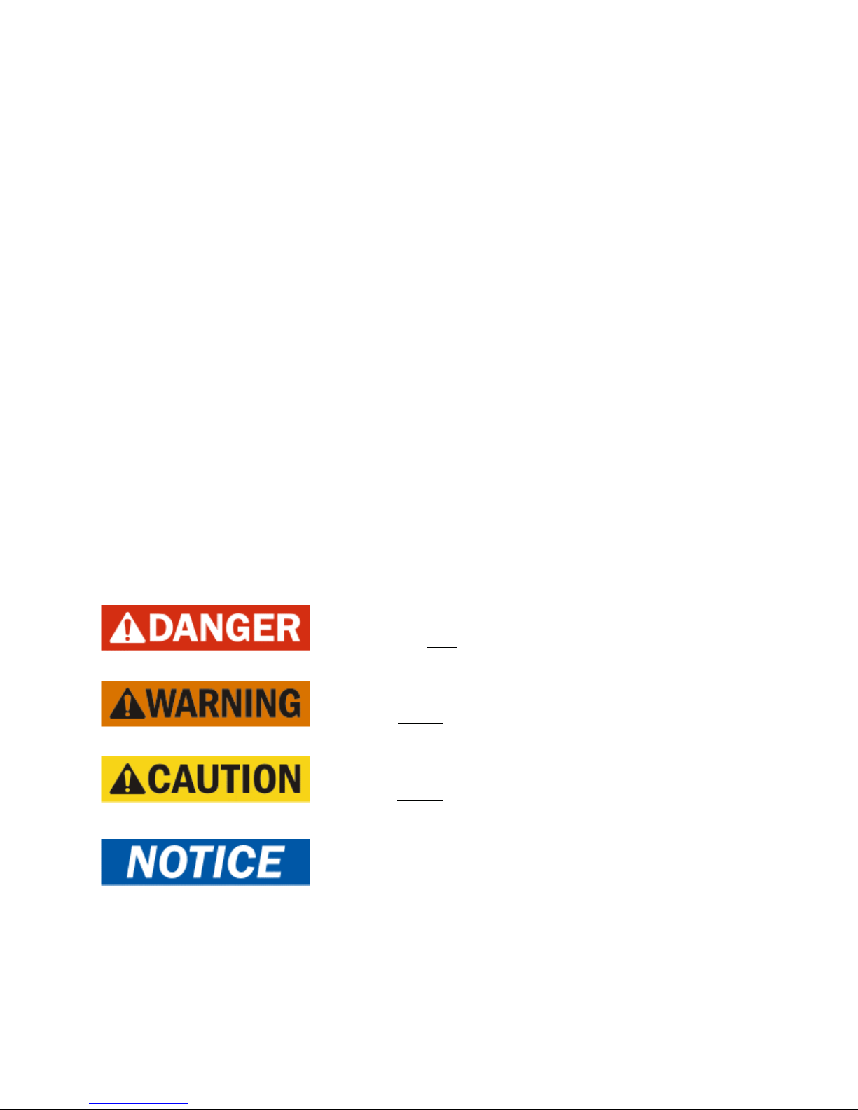
Indicate[s] an imminently hazardous situation, which, if
not avoided, will result in death or serious injury.
Indicate[s] a potentially hazardous situation, which, if not
avoided, could result in death or serious injury.
Indicate[s] a potentially hazardous situation, which, if not
avoided, could result in minor or moderate injury.
Indicate[s] a potentially unsafe situation or practice,
which, if not avoided, can result in property and/or
equipment damage only.
01/31/2012
9 309416
Page 10

Safety
3.2 Safety Precautions
The following safety precautions are a general guide to safe operation of the equipment.
This is a pressurized system. Do not attempt to remove
any part of this machine without first completely relieving
entire system of pressure. Do not attempt to service any
part of the equipment while in operation. Never attempt
to repair or modify any pressure vessel or device.
System contains hot oil. The system must be shut off prior
to servicing. Then permit system to cool down prior to
adding compressor oil or servicing the unit.
Do not use air from this system for breathing or food
processing. Air from this system will cause severe injury
or death if used for breathing or food processing.
The system is designed to compress air. Do not attempt
to compress other gases. Compression of other gases
may create a situation where an explosion or fire may
occur.
Do not use flammable solvents for cleaning system components as this can cause the unit to ignite or explode
during operation. Keep combustibles out of and away
from system inlets and any associated enclosures.
Never disable, override, or remove safeties, either temporarily or permanently.
Do not modify systems to operate equipment at a higher
pressure than specified.
01/31/2012
Never operate the machine in an enclosed area.
10 309416
Page 11

3.2 Safety Precautions (continued)
Safety
Read and understand this manual and all other safety
instructions before using this equipment. Failure to follow
operating instructions and/or failure to follow maintenance
procedures and intervals could result in personal injury,
death, and/or damage to equipment and property.
Use only Boss Industries, Inc. approved replacement
parts.
Never place machine on a grade more than 15 degrees.
Keep doors closed on the machine during operation.
Check engine’s operator manual for required service
and maintenance intervals.
This machine is equipped with safety unloading
system to prevent damage to the compressor drive
coupling. Should an attempt be made to start this
system improperly, the machine will run unloaded for
60 seconds. Likewise, if an attempt is made to
shutdown the system improperly, the unit will continue to run until the compressor system pressure
unloads below 50 PSI.
01/31/2012
11 309416
Page 12
Safety
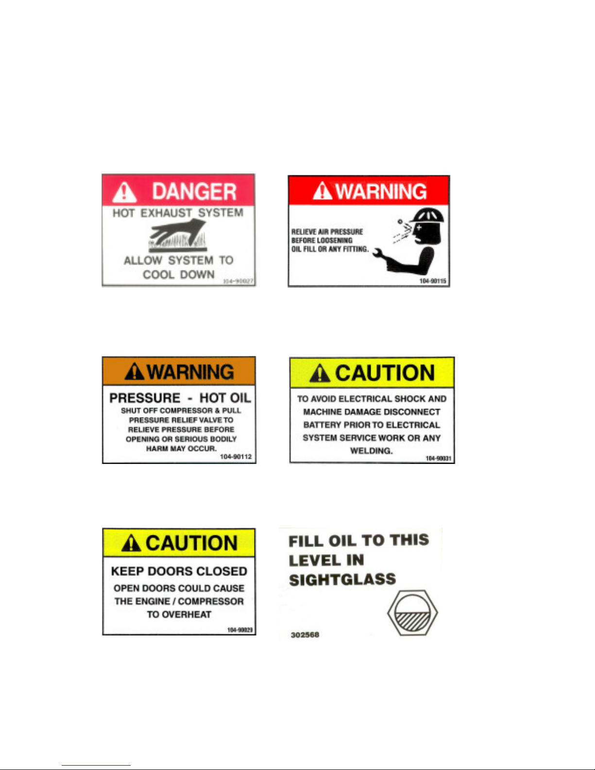
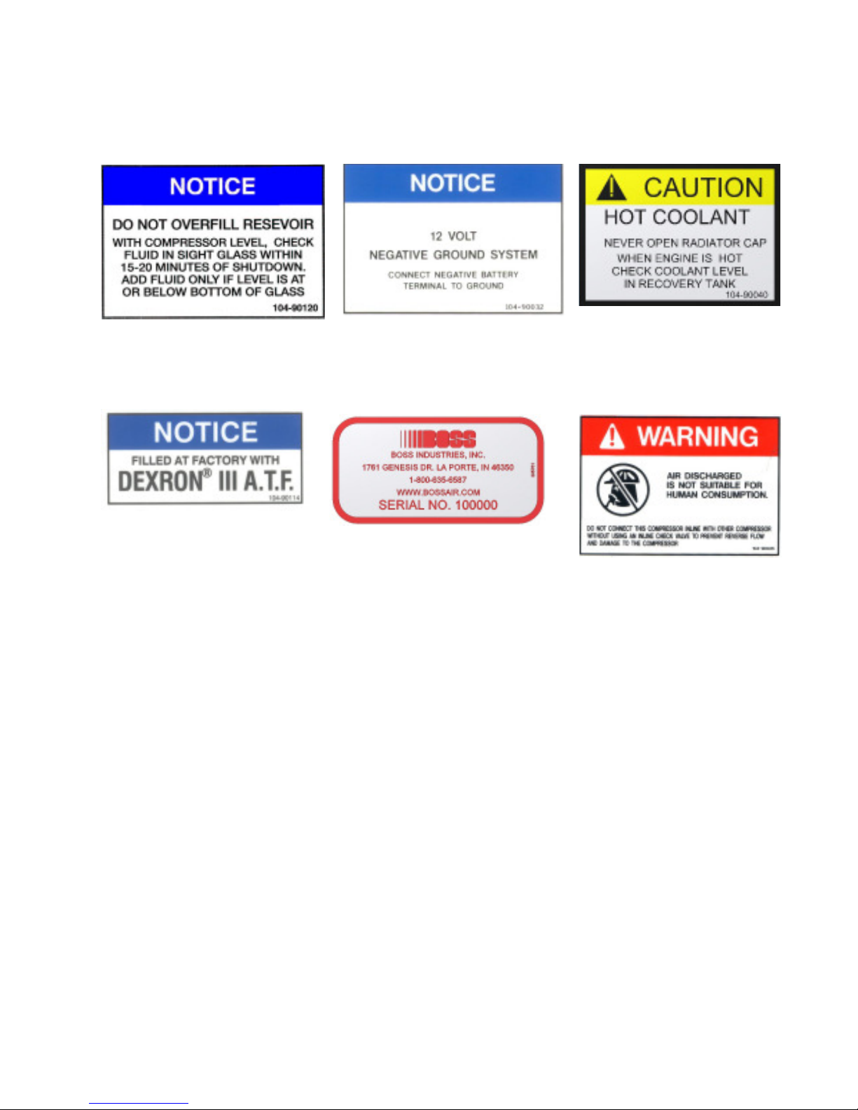
3.3 Safety and Information Decals
This machine is supplied with a full complement of safety and identification decals. These decals are
affixed to the unit during final assembly. These decals must be clearly visible and undamaged. Should
any of these decals become illegible or damaged, immediately replace the decal.
Hot Exhaust Pressurized System
Electrical ShockHot Pressurized Oil
Close Doors Oil Level
12 309416
01/31/2012
Page 13
Safety
3.3 Safety and Information Decals (continued)
Overfill Negative Ground System
Compressor Oil
Hot Coolant
Serial Tag
Breathing Air
01/31/2012
13 309416
Page 14
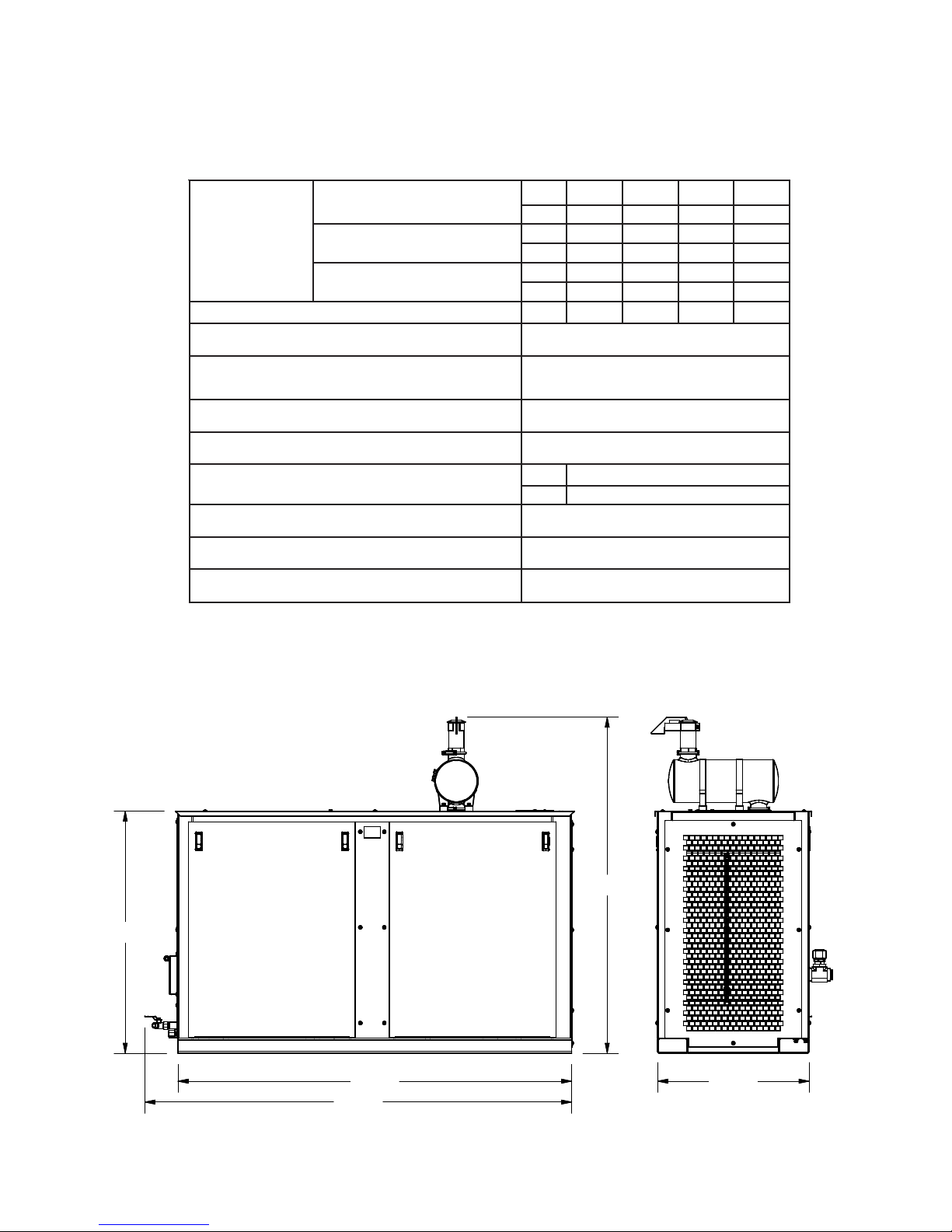
4.1 Specification Sheet
yticapaC
ISP001@
MFC 571 581 002 012
PH 83 14 54 74
ISP521@
MFC 471 481 991 902
PH 44 74 25 55
ISP061@
MFC 071 181 891 402
PH 84 15 65 75
deepStupnIrosserpmoC
MPR 0002 5212 5232 0042
dneriArosserpmoC oitaRraeG50.3htiwG01ACS
enignE
47
PH
DJ
5404
MIRTNI
REIT
4
EAS/W
B
EVIRDXUA
metsySlacirtcelEenignE CDV21
snoisnemiDesaB "2/107X"03X"8/548
knaTleuFleseiDlanoitpO
PAC L041,.LAG73
MID "5.6X"03X"87
elgnAgnitarepOenihcaM mumixam°51
elcyCytuD suounitnoC
snoitidnoCtneibmA F°521otF°04-
66.77
48.07
78.00
84.55
30.00
Specifications
*SPECIFICATIONS SUBJECT TO CHANGE WITHOUT PRIOR NOTICE*
01/31/2012
14 309416
Page 15

Description of Components
5.1Engine
The 210 DUS Air Compressor contains a John Deere, 4 cylinder diesel engine. This engine has been
selected to handle the rugged duty required for its operation. The engine speed is regulated by a
pneumatic throttle control.
5.2Drive Coupling
Power from the engine is transmitted to the compressor input shaft through a specially designed drive
coupling. The drive coupling consists of a highly torsionally flexible rubber disc that mates with an
engine flywheel flange. The coupling provides a torque limitation to protect from system overloads.
5.3 Compressor Airend
The Boss Industries, Inc. compressor airend is a positive displacement, oil flooded, rotary screw type
unit employing one stage of compression to achieve the desired pressure. Components include a
housing (stator), two screws (rotors), bearings, and bearing supports. Power from the engine flywheel
is transferred through a gear set to the male rotor. The female rotor is driven by the male rotor. There
are five lobes on the male rotor while the female rotor has six roots.
rotors mesh to compress air. Inlet air is trapped as the male lobes roll down the female grooves,
pushing trapped air along, compressing it until it reaches the discharge port at the end of the stator which
delivers smooth-flowing, pulse-free air. Being an oil flooded system, the oil serves three purposes:
lubricates the rotating parts and bearings, serves as a cooling agent for the compressed air, and seals the
running clearances.
In operation, two helical grooved
5.4 Separator System
I. Separator Tank
From the compressor airend, the compressed air and hot oil flow into a steel, ASME coded,
pressure vessel, rated at 250 PSI, that acts as an oil reservoir. This tank is the first of two stages in
separating the oil and compressed air mixture. From the bottom of the separator tank, oil is forced
to the oil filter.
II. Separator Element
At the top of the separator tank is the separator element. The separator element removes the oil
mist from the air as it is passed on to the minimum pressure valve. As the air/oil mist passes through
the outside of the media, oil gathers on the interior walls and settles to the bottom of the element.
Collected oil is returned to the compressor airend through the oil return line. The separator will filter
the oil concentration in the air to less than 3 parts per million.
15 309416
01/31/2012
Page 16

Description of Components
5.5 Pressure Relief Valve
This valve vents separator tank pressure to atmosphere should the pressure inside the tank exceed 200
PSI.
5.6 Engine Air Filter
The engine air filter is a two stage, dry type intake filter with a gravity evacuator and replaceable internal
element. On the outlet of the engine air filter is an air filter restriction indicator. This indicator serves as
a maintenance tool.
5.7 Compressor Air Filter
The compressor air filter is a two stage, dry type intake filter with a gravity evacuator and replaceable
internal element. On the outlet of the compressor air filter is an air filter restriction indicator. This
indicator serves as a maintenance tool.
5.8 Cooling Systems
I. Engine Radiator
The radiator is designed to dissipate the heat load of the engine and is mounted in front of the
specially selected engine fan. Hot engine coolant is passed through the interior of the radiator and
heat is transferred to the air that passes across the cooling fins.
II. Compressor Oil Cooler
The compressor oil cooler is designed to dissipate the heat created during the compression of air.
The oil cooler is mounted beside the engine radiator. This works similar to the engine radiator but is
designed to withstand the full compressor system working pressure.
5.9 Compressor Oil Filter
The compressor oil filter is a full flow, spin-on canister. It has been specially designed to handle 200
PSI. The oil filter is mounted downstream of the separator tank to ensure all contaminants are prevented from being passed on to the compressor oil cooler.
5.10 Compressor Oil Thermal Valve
The compressor oil thermal valve is a thermostatically controlled by-pass valve that allows varying
amounts of oil, depending upon the temperature, to by-pass the oil cooler. The oil thermal valve directs
oil flow back to the compressor airend until the system reaches 170°F. Once at system operating
temperature, the valve shifts, directing the flow through the oil cooler before returning to the compressor
airend.
01/31/2012
16 309416
Page 17

Description of Components
5.11 Compressor Inlet Valve
The compressor inlet valve is a normally open air intake valve bolted to the compressor airend. When
the system is shut down, this valve also acts as a check valve that prevents the air/oil mixture within the
compressor airend from entering the inlet piping.
5.12 Minimum Pressure Valve
To ensure there is adequate pressure to produce proper oil flow throughout the system, a spring loaded,
normally closed minimum pressure valve is set to maintain at least 80 PSI in the separator tank.
5.13 Blowdown Valve
The blowdown valve is a shuttle valve that vents system pressure to atmosphere when the system is shut
down. This is done to prevent the high torque load that would be required to overcome the static
pressure. The blowdown valve is stamped with an “I” and a “P”. The “I” side is connected to dry air
from the separator tank, and the “P” side is the pilot signal coming from the compressor inlet valve.
5.14 Blowdown Switch
The system is equipped with a blowdown switch. This switch will sense pressure in the pilot signal to
the blowdown valve. If the system contains pressure, the switch will prevent the machine from starting.
This will prevent premature damage to the drive coupling.
5.15 Discharge Pressure Regulator Valve
This valve, located downstream of the separator element, is used to set the desired discharge pressure.
This valve will send a pneumatic signal to the inlet valve to start closing when the pressure exceeds the
setpoint. This signal will also adjust the speed of the engine. This system has a maximum operating
pressure of 160 PSI.
Most air tools operating pressure range is between 90 and 125
PSI. Operating above the tools recommended pressures will
decrease the life of the tool. Strictly adhere to tool operating
pressures and torque standards set forth by the tool
manufacturer.
01/31/2012
17 309416
Page 18

Description of Components
5.16 Instrument Panel
The 210 DUS Air Compressor incorporates an instrument panel that includes numerous gauges and
controls in a single, easy to access location.
I. Engine Oil Pressure Gauge
This feature displays the oil pressure inside the engine block. When the pressure drops below 20
PSI, the system will shut down. During operation, the engine oil pressure should be approximately
60 PSI to 80 PSI.
II. Engine Coolant Temperature Gauge
This feature displays the temperature of the engine coolant. When the temperature reaches 235°F,
the system will shut down. During operation, the temperature should be approximately 190°F to
210°F.
III. Compressor Discharge Pressure Gauge
This feature displays the pressure downstream of the airend.
IV. Compressor Discharge Temperature Gauge
This feature displays the compressor discharge temperature. When the temperature reaches 245°F,
the system will shut down. During operation, the discharge temperature should be approximately
170°F to 190°F.
V. Hourmeter
The hourmeter records the total number of operating hours. It serves as a guide in following the
recommended maintenance schedule. The hourmeter will only run when the engine is operating.
VI. Voltmeter
This feature displays the voltage of the battery. The voltmeter will display when the ignition switch is
in the “RUN” position. During operation, the voltmeter should be approximately 14 VDC.
VII. Unloader Valve
This turn valve is used to limit the compressor system pressure. When the valve is in the loaded
position, the system will build to the regulator setting. If the valve is set to unloaded, the system will
build to approximately 45 PSI.
VIII. Emergency Stop Switch
The system is equipped with an emergency stop switch to immediately shutdown the machine.
IX. Bypass Switch
The bypass switch will temporarily disable the engine oil pressure shutdown during startup.
X. Ignition Switch
The ignition switch is used for starting and stopping the machine.
01/31/2012
18 309416
Page 19
Installation
1/4" TUBE
FUEL SUPPLY
(2) 3/4" MNPT AIR
SERVICE VALVES
5/16" TUBE
FUEL RETURN
6.1 System Installation Overview
The 210 DUS Air Compressor should be installed only by those who have been delegated to do so,
trained, and who have read and understand this manual. Failure to follow the instructions, procedures,
and safety precautions in this manual may result in accidents and injuries.
Install, use, and operate this system only in full compliance with all pertinent O.S.H.A., Federal, State,
and Local codes or requirements, in addition to Boss Industries, Inc. and any company’s regulations.
Do not modify this system except with written factory approval.
6.2 Placing The Machine
The first step in installing the 210 DUS Air Compressor is placing the system on a solid, level surface.
This machine is designed to run at up to a 15° grade maximum. The machine must be supplied ample
ambient air, as the system will overheat if the cooling air intake’s temperature exceeds ambient conditions.
6.3 Connecting the System Fuel Supply
Connect the fuel supply line to the 1/4” tube port on the starter side of the engine. Connect the fuel
return line to the 5/16” tube port, near the air inlet side of the turbo. Both tubes need to be SAE
30R7 rated fuel lines.
01/31/2012
Due to the precise tolerances of diesel injection systems, it is
extremely important that the fuel be kept clean and free from
dirt or water. Dirt or water in the system can cause severe
damage to both the injection pump and the injection nozzle.
Do not mix gasoline or alcohol with diesel fuel. This mixture can cause an explosion.
19 309416
Page 20

6.4 Fuel Specifications
I. High Altitude and Low Temperature Fuels
Fuels with cetane numbers higher than 40 may be needed in high altitudes or extremely low ambient
temperatures to prevent misfires and excessive smoke.
II. Cold Weather Fuel
At operating temperatures below 32° F, use a blend of No. 1D and No. 2D fuels, also known as
“Winterized” No. 2D.
Use a low sulfur content fuel having a cloud point that is at least 10 degrees below the lowest
excepted fuel temperature. Cloud point is the temperature at which wax crystals begin to form in
diesel fuel.
The viscosity of the fuel must be kept above 1.3 centistoke to provide adequate fuel system lubrication.
Use ASTM No. 2D fuel with a minimum cetane number of 40.
No. 2 diesel fuel gives the best economy and performance
under most operating conditions. See engine manufactures
operators/instruction manual for the proper engine fuel for the
brand engine in your Boss Industries, Inc. Air Compressor.
Installation
No. 1D fuel can be used; however, fuel economy will suffer.
6.5 Connecting the Air Discharge Lines
Connect the customer supplied air discharge lines, designed to handle a minimum of 200 PSI continuously, to the two 3/4” MNPT air discharge ports.
6.6 Pre-Startup Inspection
This inspection must be done prior to initial system startup.
I. Check
tied and secured.
II. Remove all tools, rags, and installation equipment from the area.
III. Verify the air discharge valves are closed.
all assemblies, clamps, fittings, hose connections, nuts, and bolts to ensure they are properly
01/31/2012
20 309416
Page 21

HOURMETER
COOLANT
TEMPERATURE
OIL PRESSURE
COMPRESSOR
TEMPERATURE
AIR PRESSURE
VOLTMETER
BYPASS SWITCH
IGNITION
SWITCH
EMERGENCY
STOP SWITCH
Installation
6.7 Machine Documentation
Record serial numbers for main components in the system.
I. Machine Serial Number __________________________________________
II. Compressor Airend Serial Number __________________________________________
III. Engine Serial Number __________________________________________
IV. Separator Tank Serial Number __________________________________________
6.8 Check Fluid Levels
The machine is factory filled prior to shipment. The proper fluid levels are also listed in the maintenance
section.
I. Separator Tank Oil Level = Halfway on the separator tank sightglass.
II. Engine Radiator Coolant Level = Bottom of the radiator fill neck.
III. Engine Coolant Recovery Bottle = Fill to the cold line.
IV. Engine Crankcase Oil Level = Full on the dipstick.
6.9 Initial Startup Preparation
I. Reconnect battery terminals. Ensure the red cable is connected to the battery’s positive terminal,
and the black cable is connected to the battery’s negative terminal.
II. Check the system for fuel, oil, and/or coolant leaks.
01/31/2012
21 309416
Page 22

Installation
This machine is equipped with safety unloading system to
prevent damage to the compressor drive coupling. Should an
attempt be made to start this system improperly, the machine
will run unloaded for 60 seconds. Likewise, if an attempt is
made to shutdown the system improperly, the unit will continue
to run until the compressor system pressure unloads below 50
PSI.
In the case of an emergency, this system is equipped with an
emergency shutdown switch. See section 7.2 for operating
instructions.
6.10 Initial Startup
At this point the system is ready to test functionality. Be sure to have completed all of the previous steps
prior to continuing.
I. Rotate the unloader valve to “UNLOAD”.
II. Hold the bypass switch and turn the ignition switch to the “START” position. If engine fails to
start, DO NOT attempt to restart until cranking motor stops rotating and the separator tank has
blown down.
III. When engine starts, release the ignition switch. Once the oil pressure has exceeded 30 PSI
release the bypass switch. Maintain the unloader valve in the “UNLOAD” position until the
engine is warm and operating smoothly, then rotate the valve to “LOAD”.
IV. Check system for leaks.
V. Allow system to run until engine coolant temperature reaches 190°F.
VI. Check for leaks again.
VII. Verify the engine speed is 1800 RPM.
VIII. Open an air service valve and verify the speed increases to 2400 RPM.
IX. Close the service valve.
X. Rotate the unloader valve to “UNLOAD”.
XI. Allow engine to idle until the air pressure has dropped below 50 PSI.
XII. Turn the ignition switch to the “OFF” position.
XIII. Initial startup testing is complete.
01/31/2012
22 309416
Page 23

Operation
7.1 Routine Operating Procedures
The 210 DUS Air Compressor should only be operated by those who have been delegated to do so,
trained, and who have read and understand this manual. Failure to follow the instructions, procedures,
and safety precautions in this manual may result in accidents and injuries.
Operate this system only in full compliance with all pertinent O.S.H.A., Federal, State, and Local codes
or requirements, in addition to Boss Industries, Inc. and any company’s regulations.
I. Routine Startup Preparation
A. Verify machine is on a level surface. Maximum allowable tilt in any direction is 15°.
B. Verify fluid levels and refill if necessary.
C. Check engine air filter’s indicator, element, clamps, and hoses.
D. Check compressor air filter’s indicator, element, clamps, and hoses.
E. Check battery cable connections for corrosion.
F. Check the condition of the engine fan belt.
G. Check for fuel, oil, and/or coolant leaks.
II. Routine Startup Procedure
A. Verify the unloader valve is in the “UNLOAD” position and all service valves are closed.
B. Hold down the bypass switch and turn the ignition switch to “START”.
C. When engine starts, release the ignition switch and continue holding bypass switch until the oil
pressure has exceeded 30PSI
D. Leave the unloader valve in the “UNLOAD” position for a minimum of 60 seconds and until the
engine temperature has reached 160°F.
E. Turn the unloader valve to the “LOAD” position.
F. Check for leaks again.
G. Open service valves for air usage.
III. Routine Shutdown Procedure
A. Close all service valves.
B. Rotate the unloader turn valve to “UNLOAD”.
C. Allow engine to idle until the air pressure has dropped below 50 PSI.
D. Turn the ignition switch to the “OFF” position.
Shutting down the machine under load will damage the engine,
drive coupling, and/or the airend. Follow normal shutdown
procedure at all times.
01/31/2012
23 309416
Page 24

Operation
7.2 Emergency Shutdown Procedure
In the event of an emergency and the 210 DUS Air Compressor must be stopped suddenly without first
unloading the compressor, the machine is equipped with an emergency shutdown switch. Do not shut
the machine off loaded except in an emergency situation. Do not operate this machine again until the
problem has been properly resolved.
I. Emergency Shutdown Procedure
A. Flip up the red emergency stop switch cover on the instrument panel.
B. Flip the toggle switch up to immediately shutdown the machine.
C. Once the machine has stopped, flip the shutdown switch and cover back down.
D. Fix the problem that required the emergency shutdown.
E. Remove the side panel and replace the 20 amp fuse on the rear of the instrument panel.
Shutting down the machine under load will damage the engine,
drive coupling, and/or the airend. Follow normal shutdown
procedure at all times.
01/31/2012
24 309416
Page 25

Maintenance
INTERVAL REQUIRED MAINTENANCE
1. Check separator tank oil level.
2. Check engine coolant level in coolant recovery bottle.
3. Check engine air filter maintenance indicator.
4. Check for fuel, oil, air, and coolant leaks.
5. Check compressor air filter maintenance indicator.
6. Check battery hold down for security.
1. Drain water from separator tank. More frequent draining may be required
under high humidity conditions.
2. Inspect lifting frame.
1. Change compressor oil and oil filter element.
2. Clean battery terminals.
3. Check battery hold-down and cables for wear.
4. Check engine air filter connections, fittings, and clamps.
5. Check compressor air filter connections, fittings, and clamps.
6. Check radiator hoses and clamps.
7. Check integrity of engine mounts.
1. Install new air filter elements. (compressor and engine)
2. Check all door gaskets, hinges, and latches.
3. Clean and flush engine cooling system
4. Check separator tank pressure relief valve.
5. Clean cooler fins on all coolers.
6. Install new fuel filter and water separator elements.
EVERY 10
HOURS OR
DAILY
EVERY 50
HOURS OR
WEEKLY
EVERY 500
HOURS OR 6
MONTHS
EVERY 1000
HOURS OR 1
YEAR
8.1 Maintenance Overview
This section contains instructions for performing the inspection, lubrication, and maintenance procedures
required to ensure the system is in proper operating condition. The importance of performing the
maintenance described herein cannot be over emphasized. A planned program of periodic inspection
and maintenance will help avoid premature failure and costly repairs. Keep an accurate logbook for
maintenance, service, and operating hours. The maintenance schedule intervals on this system are
maximum intervals. The factory recommended maintenance schedule is based on favorable operating
conditions. For continuous duty, extreme temperature, etc., service more frequently. Neglecting routine
maintenance can result in machine failure or permanent damage.
This system should be maintained only by those who have been delegated to do so, trained, and who
have read and understand this manual. Failure to follow the instructions, procedures, and safety
precautions in this manual may result in accidents and injuries.
8.2 Maintenance Schedule
01/31/2012
25 309416
Page 26

Maintenance
REBMUNTIK REBMUNTRAP NOITPIRCSED
77208
39082-421 retliFliOrosserpmoC
86219-421 tnemelErotarapeS
014903 tnemelEretliFriAenignE
014903 tnemelEretliFriArosserpmoC
590703 tiKriapeRlaeStfahSG01ACS
Compressor oil and oil filter is to be changed after the first 50
hours of operation. After this, normal intervals are to be
followed.
Check engine’s operator manual for required service and
maintenance intervals.
8.3 Recommended Spare Parts List
8.4 Parts and Service Contact Information
Phone: (800) 635-6587 (USA)
Phone: (219) 324-7776 (Outside USA)
Fax: (877) 254-4249 (USA)
Email: service@bossair.com
Website: http://www.bossair.com
01/31/2012
26 309416
Page 27

Maintenance
Accum.
Hours Date Service Performed Parts Replaced Service Work By
8.5 Maintenance Log
01/31/2012
27 309416
Page 28

Maintenance
8.6 Separator Element Replacement
When the oil vapor in the discharge air becomes excessive, the separator element may need replacing.
This should not be necessary more than once a year under normal operating conditions.
I. Replacement Procedure.
A. Shut down machine and allow to cool for approximately 10 minutes.
B. Verify entire system pressure is relieved before proceeding.
When disconnecting hose and tube, be sure to note the
location to ensure there is no confusion when
reconnecting.
C. Disconnect the 1” hose from the minimum pressure valve.
D. Disconnect the 1/4” tube from the elbow on the separator tank lid.
E. Disconnect the 1/4” tube from the elbow on the discharge pressure regulator valve.
F. Disconnect the 1/4” tube from the elbow on the blowdown valve.
G. Disconnect the 1/4” tube from the straight connector on the oil return line.
Note the location of the separator tank lid so that it can
be reinstalled in the same orientation.
H. Remove the eight 5/8” bolts holding the separator tank lid in place.
The separator tank lid has a pick-up tube installed and
damaging or moving the tube will affect the machines.
I. Lift and remove the lid from the package.
J. Remove the separator element.
Substitute filters may have inadequate working pressure
limits, resulting in filter leakage or rupture. Replacement
filters must be the same quality and type as the original Boss
Industries, Inc. separator element.
The separator element flange must have a gasket on each side
to seal the lid on one side and the vessel on the other. The
staple in each gasket acts as a static ground and must not be
removed.
K. Install a new element.
L. Reinstall the separator tank lid.
M. Reinstall the eight 5/8” bolts.
N. Uniformly tighten the bolts in a crisscross pattern to a torque of 220ft-lb.
O. Reconnect hose and tubes and ensure they are correctly located and tightened properly.
P. Start machine and check for any leaks.
01/31/2012
28 309416
Page 29

Maintenance
8.7 Engine Air Filter Replacement
Loosen the clamps that secure the engine air filter’s rear cover to the filter housing.
I.
II. Remove and clean the rear cover.
III. Remove the air filter element.
IV. Clean the canister with a damp cloth inside and out. DO NOT blow dirt out with compressed air.
Never blow dirt out of the interior of the filter housing. This
may introduce dust downstream of the filter. Instead, use a
clean damp cloth.
V. Prior to cleaning an element, check the element for damage. Damaged air filter elements must be
replaced.
A. Place a bright light inside the element to inspect for damages or leaks.
B. Inspect all seals and seal contact surfaces on the housing. Should faulty seals be evident, correct
the condition immediately.
VI. If element is undamaged, clean the air filter element.
A. The maximum number of times that an element should be cleaned is twice; however, the element
should be used no longer than a period of 1 year without changing.
Do not strike the element against any hard surfaces for cleaning as it may possibly rupture the element. Do not oil element.
B. When cleaning the element with compressed air, never let the air pressure exceed 30 PSI.
Reverse flush the element by directing the compressed air up and down the pleats in the filter
media from the inside of the element. Continue reverse flushing until all dust is removed. Should
any oil or greasy dirt remain on the filter surface, the element should be replaced.
When cleaning an element, the element will be damaged if you
exceed the recommended maximum air pressure of 30 PSI.
C. If the cleaned element is to be stored for later use, it must be stored in a clean container.
VII. Install the air filter element.
VIII. Install the rear cover and tighten clamp.
IX. Reset the air filter restriction indicator and the machine will be ready for operation.
01/31/2012
29 309416
Page 30

Maintenance
8.8 Compressor Air Filter Replacement
Loosen the wing nut that secures the compressor air filter’s cover to the filter housing.
I.
II. Remove and clean the cover.
III. Remove the air filter element.
IV. Clean the canister with a damp cloth inside and out. DO NOT blow dirt out with compressed air.
Never blow dirt out of the interior of the filter housing. This
may introduce dust downstream of the filter. Instead, use a
clean damp cloth.
V. Prior to cleaning an element, check the element for damage. Damaged air filter elements must be
replaced.
A. Place a bright light inside the element to inspect for damages or leaks.
B. Inspect all seals and seal contact surfaces on the housing. Should faulty seals be evident, correct
the condition immediately.
VI. If element is undamaged, clean the air filter element.
A. The maximum number of times that an element should be cleaned is twice; however, the element
should be used no longer than a period of 1 year without changing.
Do not strike the element against any hard surfaces for cleaning as it may possibly rupture the element. Do not oil element.
B. When cleaning the element with compressed air, never let the air pressure exceed 30 PSI.
Reverse flush the element by directing the compressed air up and down the pleats in the filter
media from the inside of the element. Continue reverse flushing until all dust is removed. Should
any oil or greasy dirt remain on the filter surface, the element should be replaced.
When cleaning an element, the element will be damaged if you
exceed the recommended maximum air pressure of 30 PSI.
C. If the cleaned element is to be stored for later use, it must be stored in a clean container.
VII. Install the air filter element.
VIII. Install the rear cover and tighten clamps. Install rubber evacuator cup facing down.
IX. Reset the air filter restriction indicator and the machine will be ready for operation.
01/31/2012
30 309416
Page 31

Maintenance
8.9 Compressor Oil
It is important that the compressor oil be of a recommended
type, and inspected and replaced as started in this manual.
The combination of a separator element loaded with dirt
and oxidized oil products together with increased air velocity as a result of this clogged conditions may produce a
critical point while the machine is in operation where ignition can take place and could cause a fire in the separator
tank.
The following are general characteristics for a rotary screw lubricant. Due to the impossibility of establishing
limits on all physical and chemical properties of lubricants which can affect their performance in the
compressor over a broad range of environmental influences, the responsibility for recommending and
consistently furnishing a suitable heavy duty lubricant must rest with the individual supplier if they choose not
to use the recommended Boss Industries, Inc. rotary screw lubricant. The lubricant supplier’s
recommendation must, therefore, be based upon not only the following general characteristics, but also upon
his own knowledge of the suitability of the recommended lubricant in helical screw type air compressors
operating in the particular environment involved.
Mixing different types or brands of lubricants is not recommended due to the possibility of a dilution of the additives
or a reaction between additives or different types.
Boss Recommended Compressor Lubricant: DEXRON® III ATF
I. Specifications
1. Flash point 400°F minimum.
2. Pour point -40°F.
3. Contains rust and corrosion inhibitors.
4. Contains foam suppressors.
5. Contains oxidation stabilizer.
Due to environmental factors, the useful life of all “extended life” lubricants may be shorter than quoted by the
lubricant supplier. Boss Industries, Inc. encourages the
user to closely monitor the lubricant condition and to participate in an oil analysis program with the supplier.
01/31/2012
No lubricant, however good and/or expensive, can replace
proper maintenance and attention. Select and use it wisely.
31 309416
Page 32

8.9 Compressor Oil (continued)
II. Adding Compressor Oil
A. Verify the machine is level to ensure oil level in sightglass will be accurate.
B. Remove any dirt around the separator tank fill cap to prevent contamination from entering the
system.
C. Remove the separator tank fill cap.
D. Inspect and clean the fill cap. Replace if necessary.
E. Dexron® III ATF can then be added until the oil level reaches halfway in the sightglass. Do not
over fill the separator tank. This will cause oil carryover in the discharge line and at blowdown.
Maintenance
Do not remove caps, plugs, or other components when the
system is running or pressurized. Stop system and relieve
all internal pressure before doing so. Failure to comply
with this warning will cause damage to property and serious
bodily harm.
Do not replace fill cap with a pipe cap; serious injury or damage could result. Replacement filters must be the same
quality and type as the original Boss Industries, Inc. fill cap.
F. Replace fill cap and tighten immediately.
III. Changing Compressor Oil
Initially the compressor oil and oil filter should be replaced after the first 50 hours of operation then
every 500 hours or 6 months. If the oil appears dirty or has a foul smell, it should be replaced
immediately.
A. Verify the machine is level to ensure oil level sightglass will be accurate.
B. Remove any dirt around the separator tank fill cap to prevent contamination from entering the
system.
Do not remove caps, plugs, or other components when the
system is running or pressurized. Stop system and relieve all
internal pressure before doing so. Failure to comply with this
warning will cause damage to property and serious bodily
harm.
C. Remove the separator tank fill cap.
D. Inspect and clean the fill cap. Replace if necessary.
E. Drain oil from the bottom of the separator tank.
F. If compressor oil filter change is required, proceed to section 8.11, “Compressor Oil Filter”.
01/31/2012
32 309416
Page 33

Maintenance
8.9 Compressor Oil (continued)
III. Changing Compressor Oil (continued)
G. Dexron III® ATF can now be added until the oil level reaches halfway in the sightglass. Do not
over fill the separator tank. This will cause oil carryover in the discharge line and at blowdown.
Do not replace fill cap with a pipe cap; serious injury or damage could result. Replacement filters must be the same
quality and type as the original Boss Industries, Inc. fill cap.
H. Replace fill cap and tighten immediately.
I. Run system briefly to see if more oil needs to be added and to ensure there are no leaks.
8.10 Compressor Oil Cooler
Any sign of leakage from the compressor oil cooler justifies a pressure test to ensure its integrity.
Cooler leaks should only be repaired by qualified service technicians. Dirt that clogs the cooling fins of
the cooler should be removed. The use of an air stream or high-pressure steam cleaner should be done
with caution so as to not damage the delicate fins. Bent cooling fins will reduce the cooling capability of
the compressor oil cooler.
8.11 Compressor Oil Filter
Initially the filter should be replaced after the first 50 hours of operation, then every 500 hours or 6
months. A dirty filter can restrict oil flow, causing high oil temperature, which will result in a system
shutdown.
I. Compressor Oil Filter Replacement
A. Verify the compressor oil system is drained.
B. Using a strap wrench, remove the oil filter and o-ring.
C. Clean o-ring seating surface on the oil filter head.
Substitute filters may have inadequate working pressure
limits, resulting in filter leakage or rupture. Replacement
filters must be the same quality and type as the original Boss
Industries, Inc. oil filter.
D. Apply a light film of oil to the new o-ring.
E. Hand tighten new filter until o-ring is seated in o-ring groove.
Mechanical over-tightening may distort the threads or damage
the filter element seal.
F. Continue tightening filter by hand an additional 1/2 to 3/4 turn.
G. Continue with Changing the Compressor Oil steps.
01/31/2012
33 309416
Page 34

Maintenance
8.12 Engine Cooling System Maintenance
The 210 DUS Air Compressor’s engine has a pressurized cooling system that contains a 50/50 mixture
of water and ethylene glycol. Maintenance of the system includes the engine coolant, belt tension, fan
integrity, and radiator. Further cooling system maintenance is defined in the engine manual.
I. Engine Coolant
A. Specifications
This diesel engine requires a balanced coolant mixture of water and ethylene glycol base
antifreeze. This protects the engine cooling system from corrosion as well as freezing damage.
The 210 DUS Air Compressor is shipped from the factory with a 50/50 mixture of water and
ethylene glycol. In tropical climates where freeze protection is not required, glycol engine
coolant should still be used to help prevent corrosion and pitting of cylinder liners.
B. Mixtures
Antifreeze concentration level should not exceed recommended levels. To do so can cause
cooling system failure.
1. A mixture of 50% antifreeze and 50% water is required for temperatures above -34° F.
2. A mixture of 60% antifreeze and 40% water is required for temperatures below -34° F.
This provides protection to -65° F.
3. Never exceed a 60% overall antifreeze mix.
C. Coolant Level
Before each start-up, when radiator is cold, the coolant level should be checked. When
needed, refill with a 50/50 solution of water and ethylene glycol, DO NOT use 100% antifreeze. The proper level for coolant in the system is to the bottom of the radiator fill neck and to
the cold line of the recovery bottle.
II. Engine Radiator
A. Radiator Core
Any sign of leakage from the engine radiator may justify a pressure test to assure its integrity.
Radiator leaks should only be repaired by qualified service technicians. Dirt that clogs the
cooling fins of the radiator should be removed. The use of an air stream or high-pressure steam
cleaner should be done with caution so as to not damage the delicate fins. Bent cooling fins will
reduce the cooling capability of the radiator.
Check the coolant level only when the engine is stopped and
the temperature is below 160° F. Failure to do so can cause
personal injury from heated coolant spray.
01/31/2012
34 309416
Page 35

Maintenance
8.12 Engine Cooling System Maintenance (continued)
II. Engine Radiator (continued)
B. Radiator Pressure Cap
If coolant continually spills from radiator through the overflow, the radiator cap should be tested
and/or replaced with a 13 PSI rated cap. Be sure cap is tightened to the proper secure position.
III. Engine Fan
Check the engine fan for cracks, loose bolts, and bent or damaged blades. Replace damaged fans
immediately. Do not run system if any of the conditions exist. Make sure the hex head bolts
mounting the fan to the water pump pulley are properly torqued to 29 ft-lbs.
Never use the fan to rotate the engine. The blade(s) can be
damaged causing a fan failure, which can result in personal
injury or property damage.
Engine Serpentine Belt
IV.
Visually inspect the engine serpentine belt. Replace belt if cracked or frayed. Check engine manual
for proper belt tension.
8.13 Battery
The battery supplied with the 210 DUS Air Compressor has been selected to have ample cold cranking
amperes for quick starts in cold weather. Keep the battery fully charged and if replacement is necessary
the new battery must be of equal or greater capacity.
Battery gas can explode causing acid burn to skin and blindness. Do not overcharge or jump the battery incorrectly.
8.14 Standby Pressure Adjustment (For 100 PSI system)
A. Close all service valves.
B. Start the machine.
C. Allow the engine to warm up.
D. The air pressure will build to 120 PSIG.
E. If the air pressure is less than 120 PSIG.
1. Adjust the discharge pressure regulator up by loosening the locknut.
2. Turn the adjusting screw clockwise.
F. If the air pressure is greater than 120 PSIG.
1. Adjust the discharge pressure regulator up by loosening the locknut.
2. Turn the adjusting screw counter-clockwise.
G. After the air pressure is set, tighten the locknut.
01/31/2012
35 309416
Page 36

Maintenance
DISCHARGE PRESSURE
REGULATOR BLEED HOLE
If your unit is rated at a higher pressure, add 20 PSI to the
working pressure for unload pressure: 160 PSI working = 180
PSI standby.
8.15 Idle Speed Adjustment
If engine speed is below 1800 RPM, contact Boss Industries, Inc.’s service department for further
assistance.
8.16 Rated Speed Adjustment
I. Rotate the unloader valve to “UNLOAD”.
II. Turn the ignition switch to the “START” position. If engine fails to start, DO NOT attempt to
restart until cranking motor stops rotating and the separator tank has blown down.
III. When engine starts, release the ignition switch. Maintain the unloader valve in the “UNLOAD”
position until the engine is warm and operating smoothly, then rotate the valve to “LOAD”.
IV. Allow system to run until engine coolant temperature reaches 190°F.
V. Open the air service valve until the discharge pressure gauge reads the desired working pressure.
Verify that air is not bleeding out of the bottom of the discharge pressure regulator. If air is bleed-
ing out, the standby pressure is set too high. Follow the steps in section 8.14 for reducing the
standby pressure.
VI. Loosen the adjustment locknut on the adjustment screw towards the front of the engine.
VII. Turn the adjustment screw clockwise to increase the speed.
VIII. Turn the adjustment screw counter-clockwise to decrease the speed.
IX. If the proper speed cannot be obtained with the adjustment screw, it may require loosening the
locknut on the air cylinder shaft and adjusting the clevis.
X. By turning the clevis onto the shaft, the engine speed will increase.
XI. By turning the clevis out, the engine speed will decrease.
XII. After proper speed is set, tighten all locknuts.
XIII. Close service valve and allow compressor to unload and the engine to return to idle.
Air Cylinder
Adjustment
Screw
Adjustment
Locknut
01/31/2012
Clevis
Locknut
36 309416
Page 37

Troubleshooting
MOTPMYS ESUAC YDEMER
tonlliwenihcaM
knarc
.snoitcennocyrettabytluaF
rofslanimretyrettabehtkcehC
.noisorrocdnassenthgit
.egatlovyrettabwoL .yrettabehtecalperroegrahC
.hctiwsnoitingiytluaF .hctiwsehtecalpeR
esoolerasnoitcennocdionelosretratS
.dedorrocro
.snoitcennocnethgitdnanaelC
.retratsrodionelosretratsytluaF
ytluafehtecalperroriapeR
.stnenopmoc
tub,sknarcenihcaM
tratstonlliw
.leufoN
tileuffotuonursahtinufI.leufddA
leufehtemirpotyrassecenebyam
.metsys
.metsysleufehtniriA
dnasnoitcennocenilleufkcehC.a
.riaperronethgit
.metsysleufehtemirP.b
.evitareponidionelosleuF
kcehc;enigneehtgniknarcelihW.a
.dionelosehttaegatlovrof
.sehctiwsytefaskcehC.b
nwodstuhsenihcaM
dnamedriahtiw
tneserp
.leuffotuO
tileuffotuonursahtinufI.leufddA
leufehtemirpotyrassecenebyam
.metsys
.detcirtserretlifleuF .retlifleufegnahC
.detavitcanwodtuhsytefaS
;detcirtserretlifliorosserpmoC.a
.retlifehtegnahc
egrahcsid/tnaloocenignehgiH.b
naelc;nwodtuhserutarepmet
.snifrelooclio/rotaidar
riaper;nekorbrognippilstlebnaF.c
.ecalperro
.liodda;wollevelliorosserpmoC.d
.liodda;wollevellioenignE.e
9.1 Troubleshooting Chart
01/31/2012
37 309416
Page 38

Troubleshooting
MOTPMYS ESUAC YDEMER
nwodstuhsenihcaM
dnamedriahtiw
)deunitnoc(tneserp
)deunitnoc(.detavitcanwodtuhsytefaS
egnahc;detcirtserretliflioenignE.f
.retlif
.eguagnwodtuhsytefasevitcefeD .eguagnwodtuhsehtkcehC
.gninoitcnuflamevlavcitatsomrehT
citatsomrehtehtecalperronaelC
.tnemele
tonlliwenihcaM
erusserppudliub
.eguagevitcefeD .eguagehtecalpeR
.taergootdnamedriA
neporoskaelrofsenilecivreskcehC
.sevlav
.nepoevlavnwodwolB
nwodwolbehtfieesotkcehC.a
.langistolipagnittegsievlav
.evlavecivresroriapeR.b
.gnilpuocevirdytluaF .gnilpuocehtecalpeR
eht,dnamedonhtiW
sdliubrosserpmoc
erusserpevissecxe
.eguagevitcefeD .eguagehtecalpeR
tonrotalugererusserpegrahcsiD
.ytluafrodetsujdaylreporp
.rotalugerehttsujdA.a
.rotalugerehtecalperroriapeR.b
riatneiciffusnI
yreviled
riaehtrofdezisrednurosserpmoC
.tnemeriuqer
.tnemeriuqerriamumixamkcehceR
.woldeepsenignE .yrassecensatsujdadnadeepskcehC
.detcirtserekatniriA
ekamdnatridrofretlifriakcehC.a
.gnikrowsirotacidniehterus
retlifehtnisnoitcurtsborofkooL.b
.gnipiptelnidna
sievlavtelniehttahtkcehC.c
.yllufgninepo
.gnilpuocevirdytluaF .gnilpuocehtecalpeR
9.1 Troubleshooting Chart (continued)
01/31/2012
38 309416
Page 39

Troubleshooting
MOTPMYS ESUAC YDEMER
evissecxE
liorosserpmoc
noitpmusnoc
.dellifrevoknatrotarapeS .levelreporpotniarD
.metsysliorosserpmocehtnikaeL
;snoitcennocdnasenilgnipipllakcehC
.yrassecensariaper
lioehtgnivomertonenilnruterliO
.tnemelerotarapesehtmorf
kcehcstidnaenilnruterliokcehC.a
saraelc;snoitcirtserrofevlav
.yrassecen
enilnruterlioehttahterusekaM.b
rotarapesehtfomottobehtsehcaer
.tnemele
.degamadtnemelerotarapeS .tnemeleehtecalpeR
riaehtrofdezisrednurosserpmoC
.tnemeriuqer
esaercniserusserpwoltagnitarepO
daolehtkcehcer;revoyrraclioeht
.stnemeriuqer
rosserpmoC
gnitaehrevo
htiwaerananidetarepogniebtinU
.riahserfdetimil
ehtpuneporotinuehtnoitisopeR
.tnemenifnoc
.nekorbroesoolsitlebnaF .ecalperronethgiT
.sreloocehtnopudliubtriD
eB.ylhguorohtreloocehtnaelC
.snifehtegamadottonluferac
.wollevelliorosserpmoC .levelreporpotllifdnakcehC
.ytridretlifliorosserpmoC .retlifehtecalpeR
.gninoitcnuflamevlavcitatsomrehT .tnemeleehtecalperronaelC
.senilliorosserpmocehtninoitcirtseR .senilehtecalperronaelC
.relooclioehtninoitcirtseR .reloocehtfosebutlanretninaelC
ehthtiwrosserpmocehtgnitarepO
.ffosrood
.nosroodtuP
.wolleveltnaloocenignE .levelreporpehtottnaloocddA
leufhgiH
noitpmusnoc
.metsysleufehtniskaeL
dnasenilleufehtllakcehC
saecalperroriaper;snoitcennoc
.yrassecen
.deepsgnitarepotcerroctatonenignE .deepsreporpstiotenigneehttsujdA
9.1 Troubleshooting Chart (continued)
01/31/2012
39 309416
Page 40

Troubleshooting
MOTPMYS ESUAC YDEMER
leufhgiH
noitpmusnoc
)deunitnoc(
.hgihoottesevlavtelnioterusserP
erusserptcerrocotrotalugertsujdA
.tinuehtrof
.detcirtsersiekatniriaenignE
gnikcehc,metsysekatniriaehttcepsnI
ro,riaper,naelc;noitcirtserynarof
.yrassecensaecalper
.gnimitnoitcejnitcerrocnI
enigneehtnisnoitacificepsottsujdA
.launam
9.1 Troubleshooting Chart (continued)
9.2 Parts and Service Contact Information
Phone: (800) 635-6587 (USA)
Phone: (219) 324-7776 (Outside USA)
Fax: (877) 254-4249 (USA)
Email: service@bossair.com
Website: http://www.bossair.com
When calling for technical support, please have machine
serial number and this manual available.
01/31/2012
40 309416
Page 41

WARRANTY
Warranty
10.1 Warranty Policy
Boss Industries, Inc. (BOSS) warrants that this Rotary Screw Compressor unit conforms to applicable
drawings and specifications approved in writing by BOSS. The unit assembly will be free from defects in
material and workmanship for a period of two (2) years from the date of initial operation or thirty (30)
months from the date of shipment, whichever period first expires. All other components and parts of BOSS
manufacture, will be free from defects in material and workmanship for a period of one (1) year from the
date of initial operation or eighteen (18) months from the date of shipment, whichever period first expires. If
within such period BOSS receives from the Buyer written notice of and alleged defect in or nonconformance of the unit, all other components and parts of BOSS manufacture and if in the judgment of
BOSS these items do not conform or are found to be defective in material of workmanship, BOSS will at its
option either, (a) furnish a Service Representative to correct defective workmanship, or (b) upon return of
the item F.O.B. BOSS original shipping point, repair or replace the item or issue credit for the replacement
item ordered by Buyer, (Defective material must be returned within thirty (30) days of return shipping
instructions from BOSS. Failure to do so within specified time will result in forfeiture of claim), or (c) refund
the full purchase price for the item without interest. Factory installed units will also include warranty on
installation for a period of one (1) year. This warranty does not cover damage caused by accident, misuse
or negligence. If the compressor unit is disassembled the warranty is void. BOSS’s sole responsibility and
Buyer’s exclusive remedy hereunder is limited to such repair, replacement, or repayment of the purchase
price. Parts not of BOSS manufacture are warranted only to the extent that they are warranted by the
original manufacture. BOSS shall have no responsibility for any cost or expense incurred by Buyer from
inability of BOSS to repair under said warranty when such inability is beyond the control of BOSS or
caused solely by Buyer.
There are no other warranties, express, statutory or implied, including those
of merchantability and of fitness of purpose; nor any affirmation of fact or
representation which extends beyond the description of the face hereof.
This warranty shall be void and BOSS shall have no responsibility to repair, replace, or repay the purchase
price of defective or damaged parts or components resulting directly or indirectly from the use of repair or
replacement parts not of BOSS manufacture or approved by BOSS or from Buyer’s failure to store, install,
maintain, and operate the compressor according to the recommendations contained in the Operating and
Parts Manual and good engineering practice. The total responsibility of BOSS for claims, losses, liabilities
or damages, whether in contract or tort, arising out of or related to its products shall not exceed the
purchase price. In no event shall BOSS be liable for any special, indirect, incidental or consequential
damages of any charter, including, but not limited to, loss of use of productive facilities or equipment, loss of
profits, property damage, expenses incurred in reliance on the performance of BOSS, or lost production,
whether suffered by Buyer or any third party.
BOSS INDUSTRIES, INC.
1761 GENESIS DRIVE
LAPORTE, IN 46350
(219) 324-7776 Phone
(219) 324-7470 Fax
41 309416
01/31/2012
Page 42

Warranty
10.2 Summary of Main Warranty Provisions
As claims, policies and procedures are governed by the terms of the BOSS Industries, Inc. (BOSS)
warranty, it is necessary to outline some of the more important provisions.
The BOSS warranty applies only to new and unused products, which, after shipment from the factory,
have not been altered, changed, repaired or mistreated in any manner whatsoever. Normal maintenance
items such as lubricants and filters are not warrantable items.
Parts not of BOSS manufacture are warranted only to the extent they are warranted by the original
manufacturer.
Damage resulting from abuse, neglect, misapplication or overloading of a machine, accessory or part is
not covered under warranty.
Deterioration or wear occasioned by chemical and/or abrasive action or excessive heat shall not
constitute defects.
Parts replacement and/or correction of defective workmanship will normally be handled by BOSS
Industries, Inc. or their authorized distributor.
Failure to file a detailed warranty claim/service report for each occurrence of material defect of
defective workmanship will cause warranty claim to be rejected.
Defective material must be returned within 30 days of receipt of shipping instructions. Failure to do so
within specified time will result in forfeiture of claim.
The distributor is responsible for the initial investigation and write up of the warranty claim.
Distributor shall be allowed no more than 30 days from date of repair to file a warranty claim/service
report.
Warranty for failure of BOSS replacement parts covers the net cost of the part only, not labor and
mileage.
The BOSS warranty does not cover diagnostic calls and travel. That is time spent traveling to the
machine to analyze the problem and returning with the proper tools and parts to correct the problem.
Boss will deduct from allowable credits for excess freight caused by sender failing to follow return
shipping instructions.
Distributors or end-user automatically deducting the value of a warranty claim from outstanding balances
due and payable to BOSS prior to receiving written notification of BOSS approval of the warranty
claim may be subject to forfeiture of the entire claim.
01/31/2012
42 309416
Page 43

Warranty
10.3 Warranty/Return Goods Instructions
The warranty/return procedure outlined below is provided to give the claimant the information necessary
to file a warranty/return claim, and enable BOSS INDUSTRIES the ability to best serve its’ customers.
Please see the following instructions to initiate a return:
Contact BOSS INDUSTRIES Returns Department by telephone at 219.324.7776 or via email at
service@bossair.com. You may also send a fax at 219.324.7470.
10.4 Warranty Claims - Preparation of Parts Return
Parts returned to the factory must be properly packaged to prevent damage during shipment. Damage to
a part as a result of improper handling or packing could be cause for denial. When addressing the package
for shipment, the following information must be on the outside of, or tagged clearly, to the package.
1. Return Goods Authorization #.
2. Distributor or end-users return address.
3. Correct factory address.
4. Number of packages pertaining to each claim.
NOTE: Our warranty requires that all defective parts be returned to BOSS INDUSTRIES freight
prepaid. Items sent without RGA number will not be accepted. Unauthorized Returns Will Immediately
Be Refused At Dock.
10.5 Return or Warranty Claims - Filing Procedures
1. Initiate through a purchase order for warranty part or request for credit.
2. RGA will accompany replacement part.
3. BOSS INDUSTRIES will confirm disposition of failed part within 30 days of receipt and or request
additional information.
4. Claim denial will result in issuance of a letter of denial.
5. BOSS INDUSTRIES will consider each claim on its’ own merit and reserves the right to accept or
reject claim request. In case of air-ends, these will be returned to the manufacturer for their analysis/
input.
6. Send Warranty Claim to:
BOSS INDUSTRIES, INC.
1761 Genesis Drive
LaPorte, IN 46350
Attn: Returns Dept.
01/31/2012
43 309416
Page 44

Warranty
10.6 Warranty Claims Provisions
An approved claim depends on the following provision:
1. An RGA # must be issued by BOSS INDUSTRIES. (See filing procedures.)
2. Failed part must be returned within 30 days of original invoice date, freight prepaid, with RGA #.
3. Part is determined to be defective.
4. Workmanship is determined to be defective.
5. Machine is within warranty period.
6. Machine has been operated within design conditions.
Claims made through distributors must be verified by distributor prior to contacting BOSS INDUSTRIES.
10.7 Damage in Transit
Do not return damaged merchandise to BOSS INDUSTRIES, please follow claim procedure.
1. Loss in transit:
The merchandise in our kit or provided in our factory installations has been thoroughly inspected or
carefully installed and tested before leaving our plant. However, regardless of the care taken at the
factory, there is a possibility that damage may occur in shipment. For this reason, it is recommended
that the unit be carefully inspected for evidence of possible damage or malfunction during the first few
hours of operation. Responsibility for the safe delivery of the kit or factory installed unit was assumed
by the carrier at the time of shipment. Therefore, claims for loss or damage to the contents of the kit or
factory installed unit should be made upon the carrier.
2. Concealed loss or damage:
Concealed loss or damage means loss or damage, which does not become apparent until the kit is
unpacked or the factory-installed unit is run by the end-user. The contents of the kit or factory installed
unit may be damaged due to rough handling while in route to its destination, even thought the kit or
factory installed unit shows no external damage. When the damage is discovered upon unpacking,
make a written request for inspection by the carrier agent within fifteen days of delivery date. Then file
a claim with the carrier since such damage is the carrier’s responsibility.
By following these instructions carefully, we guarantee our full support of your claims, to protect you
against loss from concealed damage.
3. Visible Loss or Damage
Any external evidence of loss or damage must be noted on the Freight Bill or Express Receipt, and
signed by the carrier’s agent. Failure to adequately describe such external evidence of loss, or damage
may result in the carrier refusing to honor a damage claim. The carrier will supply the form required to
file such a claim.
44 309416
01/31/2012
Page 45

Warranty
10.8 Screw Compressor Airend Exchange Program
Replacement air-ends are available from the factory. For current prices and availability, contact BOSS
INDUSTRIES, Inc. or an authorized BOSS INDUSTRIES distributor. Prices are F.O.B. shipping point.
Prices do not include labor for removal or installation.
01/31/2012
45 309416
Page 46

11.1 Frame System
Parts List
ITEM QTY PART NUMBER DESCRIPTION
1 48 120-36992
INSERT
2 1 124-28093 FILTER
3 1 300599 HEAD
4 2 960212-075
ELBOW
5
16 938604-071 WASHER
6 6 938004-062
WASHER
7 6 929104-100 BOLT
8 1 901515-030 ELBOW
9 1 960412-075
NIPPLE
10 1 922112-020 NIPPLE
11 1 309279 FRAME
12 1 306042 BRACKET
13 1 301662 VALVE
14 1 120-14966 BRACKET
15 2 120-26804
BOLT
16 1 123-66019 BATTERY
17 1 960216-100 ELBOW
18 1 922216-040 NIPPLE
19 1 125-18146 VALVE
20 2 929104-075 BOLT
21 1 150-90199
TANK
22 4 924304-145 NUT
23 2 301755-012 RELAY
24 1 961812-075 TEE
25 6 991200-031 INSERT
26 1 309408 ASSY
27 2 929104-150
BOLT
28 1 309414 BAND
29 1 309415
INDICATOR
Parts and Illustration Section
01/31/2012
46 309416
Page 47

Parts and Illustration Section
11
16
4
24
25
25
1
5
4
12
8
13
6
20
5
21
1
9
6
5
7
22
23
5
19
18
17
2
3
10
7
6
5
14
15
5
7
5
27
5
22
26
5
22
28
29
A
B
C
FLOW
DIRECTION
11.1 Frame System (continued)
01/31/2012
47 309416
Page 48

11.2 Engine System
Parts List
ITEM QTY PART NUMBER DESCRIPTION
1 1 309357 ENGINE
2 1 303150
SWITCH
3 1 308436
SENDER
4 1 902415-005 TEE
5 2 929808-125
BOLT
6 1 924404-145 NUT
7
2 150-90673
MOUNT
8 2 302764 ISOLATOR
9 4 120-16832
WASHER
10 2 925508-262 NUT
11 1 154-90975
COUPLING
12 2 938208-112
WASHER
13 1 120-36345 CYLINDER
14 1 158-36347
BRACKET
15 9 938812-250 WASHER
16 4 938808-200
WASHER
17 1 307333 FAN
19 4 929104-075 BOLT
20 4 938206-071
WASHER
21
4
925506-198
NUT
23 1 150-90665
MOUNT
24 1 150-90729
MOUNT
25 8 937806-094
WASHER
26 1 922102-015 NIPPLE
Parts List
ITEM QTY PART NUMBER DESCRIPTION
27 1 120-19071 BALL JOINT
28 4 929216-350
BOLT
29 8 929212-300
BOLT
30 1 980704-012M
ELBOW
31 1 924604-164 NUT
32 2 937808-125 WASHER
33 4 938816-350
WASHER
34 6 938604-071 WASHER
35 1 307055
BRACKET
36 8 929806-075
BOLT
37 1 301834
SWITCH
38 4 929806-125
BOLT
39 2 306030 ISOLATOR
40 4 924304-145 NUT
41 2 929808-300 BOLT
42 1 980100-400
CLAMP
43 1 302465
REDUCER
44 1 307489 BRACKET
45 1 307490
SOLENOID
46 1 929212-250 BOLT
47 1 938912-200
WASHER
49 1 308463
SENDER
50 1 309001 ADAPTER
51 1 960112-050
CONNECTOR
52 4 938908-180 WASHER
53 4 929208-750
BOLT
54
2 120-36874 SPACER
Parts and Illustration Section
01/31/2012
48 309416
Page 49

Parts and Illustration Section
17
28
24
39
20
21
9
23
13
3
15
29
12
10
37
31
11
51
27
6
42
41
50
26
41
9
7
8
4
30
19
14
35
34
40
32
5
49
38
33
9
32
5
47
15
46
10
12
45
34
19
45
8
15
29
9
40
34
44
7
43
2
25
36
52
54
53
16
11.2 Engine System (continued)
01/31/2012
49 309416
Page 50

Parts and Illustration Section
Parts List
ITEM QTY PART NUMBER DESCRIPTION
1 1 301677-305 BUSHING
2 1 302244 SWITCH
3 19 929210-400 BOLT
4 1 120-90607
BUSHING
5 1 303104 SWITCH
6 19 938810-220 PLUG
7 1 301703 AIREND
8 1 926102-145 O-RING
9 1 970804-025
GASKET
10 4 929212-800 BOLT
11 8 938812-250 TEE
12 1 300036 VALVE
13 1 926102-238 O-RING
14 1 980704-012
BOLT
15 1 973112-075 O-RING
Parts List
ITEM QTY PART NUMBER DES CRIPTION
16 4 929212-350 BOLT
17 4 938912-200 BOLT
18 1 902915-020 PLUG
19 1 960224-150
ELBOW
20 1 980804-025 TEE
21 1 304720 VALVE
22 1 308463
SENDER
23 1 301421 SWITCH
24 1 964804-025
WASHER
25 1 960404-025 WASHER
26 1 987204-025 VALVE
27 1 307682 VALVE
28 1 300112 SENDER
29 1 301594
BUSHING
11.3 Compressor System
01/31/2012
50 309416
Page 51

Parts and Illustration Section
5
15
9
3
6
2
28
6
3
19
4
10
11
18
7
22
8
1
21
29
13
23
12
24
20
25
26
16
11
17
14
27
AIR
FLOW
11.3 Compressor System (continued)
01/31/2012
51 309416
Page 52

Parts and Illustration Section
Parts List
ITEM QTY PART NUMBER DESCRIPTION
1 1 308087
VALVE
2 1 922220-000 NIPPLE
3 1 300023-175
RELIEF
4 1 960116-100
CONNECTOR
5 1 907605-040
BUSHING
6 1 901115-020 ELBOW
7
1 901515-040
ELBOW
8 1 960404-025
NIPPLE
9 1 980804-025 TEE
10 1 300057 VALVE
11 1 301827 VALVE
12 2 980704-025
ELBOW
13 1 902915-010M PLUG
14 1 922116-040 NIPPLE
15 1 922104-050
NIPPLE
16 1 902915-005
PLUG
17 3 938208-112
WASHER
18 1 977604-025
ELBOW
19 1 303192 TANK
20 1 902915-010 PLUG
21 1 960320-150
ELBOW
22 1 960212-100 ELBOW
23 3 964804-025 TEE
24 1 902915-060
PLUG
25 1 988204-025 CONNECTOR
26 3 929808-125
BOLT
27 3 937808-125 WASHER
28 1 987204-025
CONNECTOR
29 1 922224-000 NIPPLE
30 1 300107
SIGHTGLASS
31 1 960124-150
CONNECTOR
32 1 301466-150 CAP
33 1 960624-150 TEE
34 1 304210
TUBE
35 6 938206-071
WASHER
36 6 925506-198 NUT
37 3 305891
SPACER
38 6 929806-200
BOLT
39 6 938205-071 WASHER
40 1 308461
SENDER
41 2 907600-005 BUSHING
42 1 987304-025
ELBOW
43 1 988204-025M
CONNECTOR
44 1 960212-075 ELBOW
45 1 307683
SWITCH
11.4 Discharge System
01/31/2012
52 309416
Page 53

Parts and Illustration Section
26
24
35
6
45
41
20
28
42 8
13
23
32
30
31
34
25
43
15
9
10
1211
23
23
4
5
1
16
12
3
19
2
40
7
14
18
41
33
29
21
27
17
44
22
38
39
37
36
P
I
11.4 Discharge System (continued)
01/31/2012
53 309416
Page 54

Parts and Illustration Section
Parts List
ITEM QTY PART NUMBER DESCRIPTION
1 1 309283 COOLER ASSY
2 1 309303
SHROUD
3 10 938004-062 WASHER
4 14 938604-071
WASHER
5 1 902915-010
PLUG
6 6 929105-100 BOLT
7
6 938205-071
WASHER
8 6 938005-078 WASHER
9 10 929104-075
BOLT
10 1 960212-100
ELBOW
11 2 309307
GUARD
12 2 924304-145 NUT
13 2 929104-100 BOLT
14 1 907604-030
BUSHING
15 1 960012-075 ELBOW
11.5 Cooling System
01/31/2012
54 309416
Page 55

Parts and Illustration Section
9
3
4
11
11
13
4
4
12
9
3
4
10
2
6
8
7
5
1
14
15
11.5 Cooling System (continued)
01/31/2012
55 309416
Page 56

Parts and Illustration Section
Parts List
ITEM QTY PART NUMBER DESCRIPTION
1 3 924304-145 NUT
2 5 943103-025 RIVET
3 1 120-16580 SPRING
4 4 938604-071
WASHER
5 1 109-90240 DOOR
6 1 120-65681 EYEBOLT
7 2 983904-075
BOLT
8 1 40032 ASSY
9 1 977004-062
WASHER
11.6 Electrical System
01/31/2012
56 309416
Page 57

Parts and Illustration Section
2
9
4
1
4
1
4
3
6
5
7
8
11.6 Electrical System (continued)
01/31/2012
57 309416
Page 58

Parts and Illustration Section
Parts List
ITEM
QTY
PART NUMBER
DESCRIPTION
1 1 307259 PANEL
2 8 120-62264 LATCH
3 1 307896 PANEL
4
40 977004-062 WASHER
5
40 983904-075
BOLT
6 40 984004-071
WASHER
7
1 309267
ROOF
8 1 307263
COVER
9 2 120-36992 INSERT
10 1 307255 PANEL
11 1 307260
PANEL
12 3 307256 PANEL
13 2 307257
COVER
14 2 980100-300
CLAMP
15 1 307708 MUFFLER
16 2 304071
BAND
17 1 150-90915
CAP
18
4
304716 MOUNT
19 8 938205-071
WASHER
20 4 925505-273 NUT
21 4 938005-078 WASHER
22 4 925205-273 NUT
23 6 in 972303-010
PIPE
24 1
304038-MOD FOAM
25 3 304038
FOAM
26 2 962112-075
UNION
27 2 977515-075
CAP
28 1 309408 ASSY
29 2 929104-125
BOLT
30
4
938604-071 WASHER
31 2 924304-145 NUT
32 1 309414 BAND
33 1 309415
INDICATOR
11.7 Canopy System
01/31/2012
58 309416
Page 59

DETAIL A
DETAIL B
A
B
17
23
14
15
14
18
16
19
21
22
5
6
8
9
4
7
5
6
4
30
29
28
30
31
19
20
11
13
2
25
12
3
4
6
5
3
25
12
13
12
27
27
26
10
4
6
5
25
1
33
32
Parts and Illustration Section
11.7 Canopy System (continued)
01/31/2012
59 309416
Page 60

11.8 Decal System
Parts List
DESCRIPTIONPART NUMBERQTYITEM
DECAL, SERIAL TAG BOSS
30576111
DECAL, COMPR SIGHT GLASS
30256812
DECAL, FLUID104-9011413
DECAL, DIESEL ASSORTMENT
104-9019014
DECAL, DOORS CLOSED104-900292
4A
DECAL, HOT COOLANT
104-9004014B
DECAL, HOT EXHAUST
104-900271
4C
DECAL, HUMAN AIR
104-9002514D
DECAL, 12 VOLT
104-9003214E
DECAL, ELECT. SHOCK104-9003114F
DECAL, OIL RESERVOIR
104-901151
4G
DECAL, DO NOT OVERFILL104-901201
4H
DECAL, HOT OIL
104-9011214I
DECAL, COMPRESSOR OIL DRAIN BGB
30525415
DECAL, ENGINE OIL DRAIN BGB
30525516
DECAL, OPERATION DUS SAFETY
3076881
7
DECAL, WARNING READ MANUAL30003918
DECAL, WARNING FAN GUARD
30004129
Parts and Illustration Section
01/31/2012
60 309416
Page 61

Parts and Illustration Section
DETAIL A
A
9
4B
4A
2
5
8
7
4C
9
4A
1
4E
4F
6
4D
4G
4I
3
4H
11.8 Decal System (continued)
01/31/2012
61 309416
Page 62

11.9 Hose System
DETAIL A
Parts List
ITEM NOMINAL SIZE TYPE LOCATION
A 3" K -FLEX AIR FILTER TO COMPRESSOR INLET
B 3" K -FLEX AIR FILTER TO TURBO ON ENGINE
C 1 1/2" AIR HOSE COMPRESSOR DISCHARGE TO SEPARATOR TANK
D 1" AIR HOSE MINIMUM PRESSURE VALVE TO SERVICE VALVES
E
3/4" AIR HOSE SEPARATOR TANK TO OIL FILTER
F 3/4" AIR HOSE ELBOW ON THERMAL VALVE TO OIL COOLER
G 3/4" AIR HOSE TEE ON THERMAL VALVE TO FEMALE INJECTION PORT
H
3/4" AIR HOSE OIL COOLER TO TEE ON THERMAL VALVE
I 3/4" AIR HOSE BOTTOM OF SEPARATOR TANK TO REMOTE DRAIN
J
3/4" AIR HOSE ENGINE OIL PAN TO REMOTE DRAIN
K 1/4" TUBE INLET VALVE TO "P" PORT ON BLOWDOWN VALVE
L
1/4"
TUBE
ELBOW ON SEPARATOR TANK TO SOLENOID ON INLET VALVE
M 1/4" TUBE TEE ON REGULATOR TO ELBOW ON TURN VALVE
N 1/4" TUBE TEE ON INLET VALVE TO SPEED CONTROL CYLINDER
O 1/4"
TUBE
TEE ON REGULATOR TO TEE ON INLET VALVE
P 1/4" TUBE ELBOW ON SEPARATOR TANK TO OIL RETURN PORT ON COMPRESSOR
Q 1/4"
TUBE
ELBOW ON SEPARATOR TANK TO ELBOW ON TURN VALVE
R 1 3/4" RADIATOR HOSE THERMOSTAT HOUSING TO RADIATOR
S 2" R ADIATOR HOSE RADIATOR TO ENGINE
A
R
S
B
J
N
J
I
B
R
S
F
H
D
A
E
F
H
G
D
C
E
G
I
K
L
M
O
M
P
Q
Q
"P"
"I"
A
C
P
K
L
O
N
Parts and Illustration Section
01/31/2012
62 309416
Page 63

Parts and Illustration Section
11.10 System Wiring Diagram
01/31/2012
63 309416
 Loading...