

Page 1
Reference Manual
Page 2
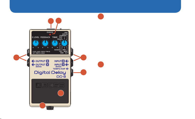
Panel Descriptions
2
1
3 4
7
2
1
DC IN jack
Accepts connection of an AC Adaptor (PSA series; sold separately).
By using an AC Adaptor, you can play without being concerned
about how much battery power you have left.
* If there are batteries in the unit while an AC adaptor is
being used, normal operation will continue should the
line voltage be interrupted (power blackout or power cord
disconnection).
* Use only the specied AC adaptor (PSA-series).
* If the AC adaptor is connected while power is on, the power
supply is drawn from the AC adaptor.
2
CHECK indicator
5
6
This is a combination indicator, which indicates whether
the eect is on or o, indicates the various functions, and
functions as the battery check indicator.
The indicator lights when an eect is ON.
* If this indicator goes dim or no longer lights while an eect
is ON, or when the functions are indicated, the battery is
near exhaustion and should be replaced immediately. For
instructions on changing the batteries, refer to “Changing
the Battery” (p. 21).
* The CHECK indicator shows whether the eect is on or o,
and indicates the dierent functions. It does not indicate
whether the power to the device is on or not.
Page 3
3
OUTPUT-A (MONO) jack,
OUTPUT-B jack
The output jacks are used to connect the unit to an amplier
or another eects unit.
* The unit’s functions dier according to how it is connected.
Refer to “Setting the Output Method” (p. 15).
4
INPUT-A (MONO) jack,
INPUT-B jack
These jacks accept input signals (coming from a guitar, some
other musical instrument, or another eects unit).
* The unit’s functions dier according to how it is connected.
Refer to “Setting the Output Method” (p. 15).
* The INPUT-A (MONO) and INPUT-B jacks double as power
switches. Power to the unit is turned on when you plug into
the INPUT-A (MONO) or INPUT-B jack; the power is turned
o when the cable is unplugged. Be sure to disconnect any
cord plugged into the INPUT-A (MONO) or INPUT-B jack
when not using this eects device.
Panel Descriptions
5
TEMPO/EXP jack
This jack is for connecting a footswitch (FS-5U, FS-6, FS-7; sold
separately) or an expression pedal (Roland EV-5, FV-500H,
FV-500L, EV-30; sold separately).
This jack lets you use a footswitch to set the tempo, control
the loop, or turn TWIST on/o, or use an expression pedal to
control various parameters.
* For details, refer to “Setting the Tempo Using a Footswitch”
(p. 12),
“Using a footswitch to control the loop function” (p. 14),
“Using the TWIST Function” (p. 14), or
“Control Using an Expression Pedal” (p. 19).
6
Pedal switch
This is used for switching the eect on and o, and for
switching between the dierent functions.
7
Thumbscrew
When this screw is loosened, the pedal will open, allowing you
to change the battery.
* For instructions on changing the battery, refer to “Changing
the Battery” (p. 21).
3
Page 4
Panel Descriptions
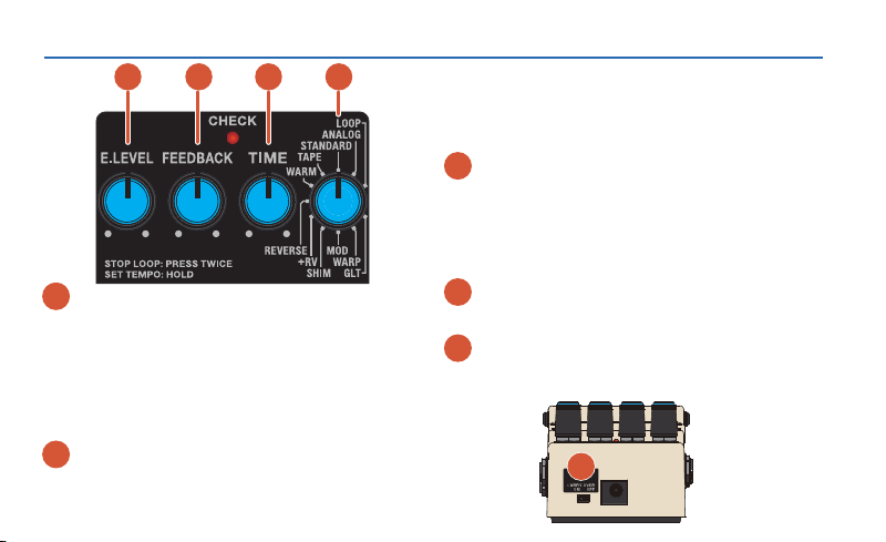
8
[E.LEVEL] knob
This adjusts the volume of the eect sound. Turn the knob
clockwise to increase the eect sound. When set at the three
o’clock position, the eect is played at the same volume as the
direct sound.
* When the [E.LEVEL] knob is set to MAX while in REVERSE
mode, only the eect sound is output, with the eect sound
at the same level as the input sound.
9
[FEEDBACK] knob
This adjusts the feedback level. The number of times the delay
sound is repeated increases as the knob is turned to the right.
4
11 10 9 8
* This cannot be used in LOOP mode.
* In GLT mode, this adjusts the depth of the GLT eect.
* Oscillation may occur when the knob is set at certain
positions.
10
[TIME] knob
This adjusts the delay time. Turning the knob clockwise
lengthens the delay time.
* This cannot be used in LOOP mode.
* The delay times that can be set vary according to the
position of the [MODE] knob.
11
[MODE] knob
This switches the delay eect.
12
[CARRYOVER] switch
This selects whether the delay sound remains (ON) or does not
remain (OFF) when you turn o the eect.
12
Page 5
Panel Descriptions
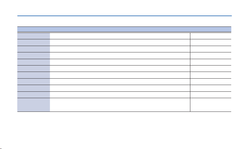
Characteristics of each mode
MODE knob Explanation Delay time
STANDARD Clear digital delay. 20–800 ms
ANALOG Mild analog delay. 20–800 ms
TAPE Sound with the modulation that is distinctive of a tape echo unit. 20–800 ms
WARM Mild digital delay. 20–800 ms
REVERSE Delay played backward. 300–5000 ms
+RV Delay with reverb. 20–800 ms
SHIM Delay with pitch-shifted sound added. 200–800 ms
MOD Digital delay with modulation. 20–800 ms
WARP Creates a dreamlike sound. 20–800 ms
GLT Creates a machine-gun-like sound. 10–400 ms
LOOP
*1: In LOOP mode, the maximum recording time is 20 seconds for stereo input or 40 seconds for mono input.
* If you specify the long delay output setting, the delay time is doubled. For details, refer to “Setting the Output Method” (p. 15).
Records your performance, and repeatedly plays it back.
For more information, refer to “Using the LOOP (Overdubbing) Function” (p. 13).
sec. *1
40
5
Page 6
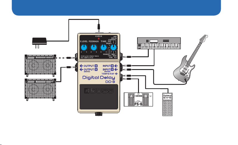
Connections
AC Adaptor
(PSA series; sold
separately)
Keyboard
Electric Guitar
Guitar Amplier
You can obtain a variety of dierent delay eects by changing how the connections are made.
6
For more information, refer to “Setting the Output Method” (p. 15).
Footswitch
(FS-6 etc.)
Expression Pedal
(Roland EV-5 etc.)
Page 7
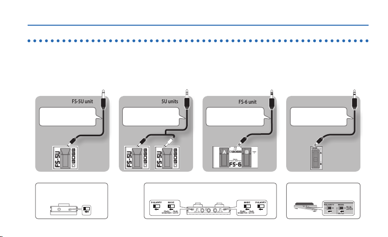
Footswitch connections
Refer to the diagrams for details on the appropriate cables to use and the setting of the polarity switch.
* When connecting a footswitch, you must turn o the power before connecting or disconnecting cables. Failure to observe this
precaution will cause malfunctions.
Connect to TEMPO/EXP jack Connect to TEMPO/EXP jack Connect to TEMPO/EXP jack Connect to TEMPO/EXP jack
Connecting one FS-5U unit
1/4” phone type
1/4” phone type
,
Connecting two FS-5U units
Stereo 1/4” phone type
1/4” phone type × 2
RING TIP
,
Connecting one FS-6 unit
Stereo 1/4” phone type
Stereo 1/4” phone type
,
A&B
Connecting one FS-7 unit
Stereo 1/4” phone type
Stereo 1/4” phone type
A&B
,
Connections
FS-5U POLARITY switch
FS-6 MODE/POLARITY switch FS-7 MODE/POLARITY switch
7
Page 8

Connections
Caution when making connections
* To prevent malfunction and equipment failure, always turn down the volume, and turn o all the units before making any
connections.
* Do not use connection cables that contain a built-in resistor.
* Before turning the unit on/o, always be sure to turn the volume down. Even with the volume turned down, you might hear some
sound when switching the unit on/o. However, this is normal and does not indicate a malfunction.
* Once the connections have been completed, turn on power to your various devices in the order specied. By turning on devices in
the wrong order, you risk causing malfunction and/or damage to speakers and other devices.
• When powering up: Turn on the power to your guitar amp last
• When powering down: Turn o the power to your guitar amp rst
* When operating on battery power only, the unit’s indicator will become dim when battery power gets too low. Replace the battery
as soon as possible.
8
Page 9

Operating the Unit
2 3 4 5
1
1. Turn on the eect.
After you have nished making the connections, press the pedal
switch to turn the eect on (the CHECK indicator lights red).
* When in LOOP mode, the eect cannot be switched on or o.
* You can obtain a variety of dierent delay eects by changing
how the connections are made. For more information, refer to
“Setting the Output Method” (p. 15).
2. Select the mode.
Use the [MODE] knob to select the mode to be used.
* Operation diers depending on the mode. For details, refer to
“Characteristics of each mode” (p. 5).
3. Adjust the delay time.
Adjust the delay time with the [TIME] knob.
4. Adjust the feedback level.
Use the [FEEDBACK] knob to adjust the feedback level (or how
much the sound is repeated).
* Oscillation may occur with certain input sounds, or when the
knob is set at certain positions.
5. Adjust the volume.
Adjust the volume level of the eect sound with the [E.LEVEL]
knob.
9
Page 10

Using the Tempo Delay
MODE: STANDARD
(SHIM/MOD/GLT/WARP)
Tempo input allows you to set the delay time to match the tempo
of a song by repeatedly pressing the pedal switch in time with the
desired tempo. You can also use this method to change the delay
time to any setting you like as you perform.
Using tempo input, the delay time can be set within the range of
67–10000 ms.
This corresponds to a range of BPM=24–300.
Setting the TAP DIVISION
This species the note value corresponding to the delay time that
is actually set when you press the pedal at quarter note intervals.
Before using tap delay, you must rst specify this TAP DIVISION.
1. Make the connection to the INPUT-B jack and leave
nothing connected to the INPUT-A (MONO) jack.
2. Hold down the pedal switch and insert the plug to
INPUT-A (MONO) jack.
The unit is now in TAP DIVISION setting mode, and the CHECK
indicator is lit orange.
3. Select the TAP DIVISION.
Use the [MODE] knob to select the TAP DIVISION value.
10
According to the value that you select, the actual delay time will be
as shown in the illustration.
Timing at which you
press the pedal
MODE: LOOP
MODE: ANALOG
MODE: TAPE
MODE: WARM
MODE: REVERSE
MODE: +RV
* With the factory settings, this is set to “quarter notes
(STANDARD).”
* In GLT mode, the delay time is 1/4 of the above lengths.
4. Saving the setting.
When you press the pedal switch of the unit, the CHECK
indicator blinks orange at high speed, and the setting is saved.
After the setting is saved, the unit returns to the normal
operating state.
Page 11

* Never switch o the power while the CHECK indicator is
ashing rapidly.
* This setting is retained even while the power is turned o.
Setting the tempo using the Pedal switch
1. Select the mode.
Use the [MODE] knob to select the mode to be used.
* Tempo input cannot be used in LOOP mode.
2. Switch to TEMPO mode.
Hold down the pedal switch for at least two seconds (the CHECK
indicator lights green).
* When a footswitch (the FS-5U, FS-6, FS-7; sold separately) is
connected to the TEMPO/EXP jack, you won’t be able to enter
TEMPO mode by pressing the pedal switch.
3. Begin inputting the tempo.
Press the pedal switch at quarter-note intervals in
synchronization with the tempo of the song. (If the eect is o,
the CHECK indicator blinks red; if the eect is on, the CHECK
indicator blinks red/green.)
The delay time is set according to the tempo and the TAP
DIVISION value.
Using the Tempo Delay
For example if TAP DIVISION is set to a dotted eighth note
(WARM), and you press the pedal switch at quarter-note
intervals in synchronization with the tempo of the song,
the tempo is calculated based on that spacing, and the
delay is applied with a length of a dotted eighth note at
the calculated tempo.
4. Finish inputting the tempo.
Hold down the pedal switch for at least two seconds to
complete the setting (the CHECK indicator lights red).
* The tempo may become confused momentarily when you go
from Step 3 to Step 4.
* Turning the [TIME] knob resets the delay time to that
indicated by the knob’s position.
11
Page 12

Using the Tempo Delay
Setting the Tempo Using a Footswitch
Connecting a footswitch (FS-5U, FS-6, FS-7; sold separately) to the
TEMPO/EXP jack lets you set the tempo delay by inputting the
tempo.
* You can input the tempo with the footswitch regardless of
whether the eect is on or o.
1. Connect the Footswitch to the TEMPO/EXP jack.
* When connecting a footswitch, you must turn o the power
before connecting or disconnecting cables. Failure to observe
this precaution will cause malfunctions.
2. Select the mode.
Use the [MODE] knob to select the mode to be used.
* Inputting the tempo is not possible in LOOP mode.
3. Start inputting the tempo.
Press the footswitch at quarter-note intervals in synchronization
with the tempo of the song. (If the eect is o, the CHECK
indicator blinks red; if the eect is on, the CHECK indicator
blinks red/green.)
Footswitch Operation
12
If one FS-5U unit is
connected
Use the pedal to input the tempo.
Footswitch Operation
If two FS-5U units
are connected
If an FS-6 or FS-7
are connected
The delay time is set according to the tempo and the TAP
DIVISION value.
For example if TAP DIVISION is set to a dotted eighth note
(WARM), and you press the pedal switch at quarter-note
intervals in synchronization with the tempo of the song,
the tempo is calculated based on that spacing, and the
delay is applied with a length of a dotted eighth note at
the calculated tempo.
* Tempo input using the Pedal Switch is not possible.
* Turning the [TIME] knob resets the delay time to that
indicated by the knob’s position.
* The CHECK indicator ashes red in time with the interval with
which you press the pedal.
Use the TIP pedal to input the tempo.
Use switch B to input the tempo.
Page 13

Using the LOOP (Overdubbing) Function
With the LOOP function, you can record up to 40 seconds of your
performance, and then have that content played back repeatedly.
You can also layer this as you perform something else, then record
these together (overdub).
1. Select LOOP.
Set the MODE knob to LOOP (the CHECK indicator goes out).
2. Begin recording.
Recording starts when you press the pedal switch (the CHECK
indicator ashes red).
* The maximum recording time is 20 seconds for stereo input or
40 seconds for mono input.
* Recording continues even if you release the pedal switch.
3. Stop recording0start playback.
When in the recording state, press the pedal switch to stop
recording and transition to playback (the CHECK indicator is
lit green).
4. Start overdubbing.
When in the playback state, press the pedal switch to start
overdubbing (the CHECK indicator is lit orange).
5. Stop overdubbing0start playback.
When in the overdubbing state, press the pedal switch to stop
overdubbing and transition to playback (the CHECK indicator
is lit green).
6. Adjust the volume.
Use the [E.LEVEL] knob to adjust the volume of the playback
sound.
7. Finish playback.
To stop playback, press the pedal switch twice. (If there is
recorded data, the CHECK indicator blinks green.)
* Press the pedal switch two times in succession, keeping the
interval between presses to one second or less.
Hold down the pedal switch for two seconds or longer
to delete the recorded content.
13
Page 14

Using the LOOP (Overdubbing) Function
Using a footswitch to control the loop function
If a footswitch (FS-5U, FS-6, FS-7; sold separately) is connected to the
TEMPO/EXP jack, you can stop playback or erase.
* When connecting a footswitch, you must turn o the power
before connecting or disconnecting cables. Failure to observe
this precaution will cause malfunctions.
Footswitch Operation
Press the pedal to stop.
Long-press the pedal to delete.
Press the RING pedal to delete.
Press the TIP pedal to stop.
Press switch A to delete.
Press switch B to stop.
14
If one FS-5U unit
is connected
If two FS-5U units
are connected
If an FS-6 or FS-7
are connected
Using the TWIST Function
If a footswitch (sold separately: FS-5U, FS-6, FS-7) is connected to
the TEMPO/EXP jack, you can use the TWIST function which creates
an aggressive sense of rotation.
* When connecting a footswitch, you must turn o the power
before connecting or disconnecting cables. Failure to observe
this precaution will cause malfunctions.
* Twist function cannot be used in LOOP mode.
Footswitch Operation
If two FS-5U units
are connected
If an FS-6 or FS-7
are connected
* If only one FS-5U unit is connected, the TWIST function
cannot be used.
Press the RING pedal to apply the TWIST
eect.
Press switch A to apply the TWIST eect.
Page 15

Setting the Output Method
With the DD-8, you can obtain a variety of dierent delay eects by
changing how the connections are made.
Normal
This produces mono delay with A input and A output.
A
A
Guitar Amplier GuitarDD-8
Long
This produces long delay with A input and B output.
B
A
Guitar Amplier GuitarDD-8
MODE Normal delay Long delay
LOOP 40 sec. *1 40 sec.
ANALOG 20–800 ms 40–1600 ms
TAPE 20–800 ms 40–1600 ms
WARM 20–800 ms 40–1600 ms
REVERSE 300–5000 ms 600–10000 ms
+RV 20–800 ms 40–1600 ms
SHIM 200–800 ms 400–1600 ms
MOD 20–800 ms 40–1600 ms
WARP 20–800 ms 40–1600 ms
GLT 10–400 ms 20–800 ms
*1: In LOOP mode, the maximum recording time is 20 seconds for
stereo input or 40 seconds for mono input.
15
Page 16

Setting the Output Method
B
Direct Mute
This produces eect output with B input and A output.
A
Stereo
With A input and A/B output, this provides mono-in stereo-out
delay.
RETURN SEND
* The direct sound is not output from A, regardless of whether
* Be sure to lower the output level of any device being
DD-8
INPUT
Guitar Amplier Guitar
the eect is on or o.
connected.
16
ABA
Guitar Amplier Guitar DD-8
With A/B input and A/B output, this provides stereo-in stereo-out
delay.
B
A
Guitar Amplier Guitar Stereo Eect Unit
* You can select any of three types of stereo delay modes.
For more information, refer to “Setting the Mode for Stereo
Delay” (p. 18).
DD-8
Keyboard
B
A
(chorus, anger etc.)
Page 17

Eect + Direct
This produces eect + direct output with B input and A/B output.
B B
A
Setting the Output Method
(Direct sound)
* A: eect, B: direct
* Switching o the eect outputs the direct sound from A.
(Eect sound)
Guitar Amplier
DD-8 Guitar
17
Page 18

Setting the Mode for Stereo Delay
When using the DD-8 as a stereo delay, you can choose among
three dierent types of stereo delay eect.
* For detailed information on how to make the connections for
stereo delay, refer to “Stereo” (p. 16).
1. Make the connection to the INPUT-A (MONO) jack
and leave nothing connected to the INPUT-B jack.
2. Hold down the pedal switch and insert the plug to
INPUT-B jack.
The setting mode for stereo delay is enabled, and the CHECK
indicator lights in orange.
3. Select the stereo delay eect.
Use the [MODE] knob to select the mode for stereo delay.
MODE knob Eect Explanation
LOOP panning Panning delay.
ANALOG wide stereo
STANDARD
completely
independent
stereo
18
Stereo delay with a
sense of wide space
in the reverberant
sound.
Completely
independent delays
for A and B.
MODE knob Eect Explanation
TAPE
WARM
REVERSE
+RV
SHIM
MOD
GLT
WARP
* With the factory settings, this is set to “Completely
independent delays for A and B”.
panning Panning delay.
4. Save the settings.
Press the pedal switch to make the CHECK indicator rapidly ash
in orange and save the settings.
After the settings have been saved, the unit returns to normal
operation.
* Never switch o the power while the CHECK indicator is
ashing rapidly.
* This setting is retained even while the power is turned o.
Page 19

Control Using an Expression Pedal
Connecting an expression pedal (Roland EV-5, BOSS FV-500H,
FV-500L, EV-30; sold separately) to the TEMPO/EXP jack enables you
to control the respective parameters of the [E.LEVEL], [FEEDBACK],
and [TIME] knobs.
* Use only the specied expression pedal. By connecting any
other expression pedals, you risk causing malfunction and/or
damage to the unit.
Making the Settings for Expression Pedal Functions
1. Hold down the pedal switch and connect the
expression pedal.
The function-setting mode for the expression pedal is enabled
and the CHECK indicator lights in orange.
* The setting mode cannot be entered while LOOP mode is
selected.
* When connecting an expression pedal to the TEMPO/EXP jack,
set the minimum volume for the connected expression pedal
to the “MIN” position.
2. Make the settings for the parameters.
3. Save the parameters.
Turn the [E.LEVEL], [FEEDBACK], and [D.TIME] knobs to set the
maximum values of the ranges you want to control. If you don’t
want to control a particular parameter with the expression
pedal, set its value to the “MIN” position.
* You can set only the maximum value of a parameter range
controlled using the expression pedal. Setting the minimum
value is not possible.
Press the pedal switch to make the CHECK indicator rapidly ash
in orange and save the settings.
After the settings have been saved, the unit returns to normal
operation.
* Never switch o the power while the CHECK indicator is
ashing rapidly.
* This setting is retained even while the power is turned o.
19
Page 20

Use of Battery
* If operating this unit on batteries, please use alkaline batteries.
* If you handle batteries improperly, you risk explosion and uid leakage. Make sure that you carefully observe all of the items related
to batteries that are listed in “USING THE UNIT SAFELY” and “IMPORTANT NOTES” (supplied on a separate sheet).
* When operating on battery power only, the unit’s indicator will become dim when battery power gets too low. Replace the battery
as soon as possible.
* Batteries should always be installed or replaced before connecting any other devices. This way, you can prevent malfunction and
damage.
20
Page 21

Changing the Battery
Thumbscrew
Battery Snap
Cord
Battery Snap
9 V Battery
Battery Housing
Pedal
Spring Base
Coil Spring
Guide Bush
Hole
1. Hold down the pedal and loosen the thumbscrew,
then open the pedal upward.
* The pedal can be opened without detaching the thumbscrew
completely.
2. Remove the old battery from the battery housing,
and remove the snap cord connected to it.
3. Connect the snap cord to the new battery, and place
the battery inside the battery housing.
* Be sure to carefully observe the battery ’s polarity (+ versus -).
4. Slip the coil spring onto the spring base on the back
of the pedal, and then close the pedal.
* Carefully avoid getting the snap cord caught in the pedal, coil
spring, and battery housing.
5. Insert the thumb screw into the guide bush hole and
tighten it securely.
21
Page 22

Main Specications
BOSS DD-8: Digital Delay
Nominal Input Level -20 dBu
Input Impedance 1 MΩ
Nominal Output Level -20 dBu
Output Impedance 1 kΩ
Recommended Load
Impedance
Power Supply
Current Draw
Dimensions
Weight 440 g / 1 lb (including battery)
10 kΩ or greater
DC 9 V: Alkaline battery (9 V, 6LR61)
AC adaptor (PSA series: sold
separately)
65 mA (DC 9 V)
* Expected battery life under
continuous use (These gures
will vary depending on the actual
conditions of use.)
Alkaline: Approx. 5 hours
73 (W) x 129 (D) x 59 (H) mm
2-7/8 (W) x 5-1/8 (D) x 2-3/8 (H)
inches
Owner’s Manual, Leaet (“USING THE
Accessories
Options
* 0 dBu = 0.775 Vrms
* This document explains the specications of the product
at the time that the document was issued. For the latest
information, refer to the Roland website.
UNIT SAFELY,” “IMPORTANT NOTES,”
and “Information”),
Alkaline battery (9 V, 6LR61)
AC adaptor: PSA series
Footswitch: FS-5U, FS-6, FS-7
Expression pedal: FV-500H, FV-500L,
EV-30, Roland EV-5
22
© 2019 Roland Corporation 01
 Loading...