

Page 1
VIRTUALLY INVISIBLE
191 SPEAKERS
,QVWDOODWLRQ*XLGH
,QVWDOODWLRQVDQOHLWXQJ
*XtDGHLQVWDODFLyQ
1RWLFHG¶LQVWDOODWLRQ
*HEUXLNHUVKDQGOHLGLQJ
®
Page 2

SAFETY INFORMATION
Important words of caution
Please read this owner’s guide completely before you start. Then carefully consider your experience using the tools
and taking the precautions referred to here. If you have doubts about doing this installation, you should contact
either the dealer you purchased the product from, an electrician, or a professional audio/video installer. You can
describe the job and request a cost estimate before committing to installation service.
WARNING:
70, and/or the National Fire Alarm Code, ANSI/NFPA 72, as applicable. The wiring method and compartment shall be
such as not to interfere with the operation of the speaker.
CAUTION:
Installation shall be in accordance with the applicable section of the National Electrical Code, ANSI/NFPA
Consult local building codes before you get started with this installation.
EnglishFrançaisNederlands DeutschItaliano
CAUTION:
CAUTION:
This product is not intended for use in Air-Handling Plenum Spaces.
Failure to follow the instructions in this owner’s guide voids all warranties on your speakers.
Use these instructions with wood frame or similar construction only
Each speaker requires 81/16 in. (20.5 cm) of horizontal space, and 14 in. (35.6 cm) of vertical space inside the wall or
ceiling, plus a minimum of 4
(1.9 cm) thick.
Bose recommends installing these speakers only in wood frame or similar construction where there is enough
space between studs, as is found in 2 x 4 or 2 x 6 wall/ceiling construction. The instructions in this guide are
specific to that type of installation only.
Note:
These speakers are not designed for installation in walls or ceilings of masonry.
1
/8in. (10.5 cm) of depth from the face of wallboard that is a maximum of 3/4 in.
Important Safety Instructions
1. Read these instructions - for all components before using this product.
2. Keep these instructions - for future reference.
3. Heed all warnings - on the product and in the owner’s guide.
4. Follow all instructions.
5. Do not block any ventilation openings, install in accordance with the manufacturer’s instructions.
6. Only use attachments/accessories specified by the manufacturer.
Bose® Virtually Invisible® 191 Loudspeakers comply with the following specifications:
This product conforms to the EMC Directive 89/336/EEC and to the Low Voltage Directive 73/23/EEC.
The complete Declaration of Conformity can be found on <www.bose.com>.
For your records
Serial numbers are located on the center rear of each of the Virtually Invisible® 191 speakers.
Serial numbers:______________________________ and __________________________________
Dealer name:_______________________________________________________________________
Dealer phone:_____________________________Purchase date: __________________________
We suggest you keep your sales receipt and warranty card together with this owner’s guide.
2
Page 3

English Español NederlandsDeutsch Français
CONTENTS
INTRODUCTION 4
Before you begin... . . . . . . . . . . . . . . . . . . . . . . . . . . . . . . . . . . . . . . . . . . . . . . . . . . . . . . . . . . . . . . . . . . . . . . . . . . . . 4
What makes this speaker better also makes it different . . . . . . . . . . . . . . . . . . . . . . . . . . . . . . . . . . . . . . . . . . . . . . . 4
PREPARATION 5
Unpacking . . . . . . . . . . . . . . . . . . . . . . . . . . . . . . . . . . . . . . . . . . . . . . . . . . . . . . . . . . . . . . . . . . . . . . . . . . . . . . . . . . 5
Other equipment you will need . . . . . . . . . . . . . . . . . . . . . . . . . . . . . . . . . . . . . . . . . . . . . . . . . . . . . . . . . . . . . 5
Deciding on speaker placement . . . . . . . . . . . . . . . . . . . . . . . . . . . . . . . . . . . . . . . . . . . . . . . . . . . . . . . . . . . . . . . . . 6
Three tips for determining speaker placement . . . . . . . . . . . . . . . . . . . . . . . . . . . . . . . . . . . . . . . . . . . . . . . . . . 6
Consider which shape you prefer for your speakers . . . . . . . . . . . . . . . . . . . . . . . . . . . . . . . . . . . . . . . . . . . . . 7
Considering your wall type and the approach it requires . . . . . . . . . . . . . . . . . . . . . . . . . . . . . . . . . . . . . . . . . . 7
For placement in walls . . . . . . . . . . . . . . . . . . . . . . . . . . . . . . . . . . . . . . . . . . . . . . . . . . . . . . . . . . . . . . . . . . . . 7
For placement in ceilings . . . . . . . . . . . . . . . . . . . . . . . . . . . . . . . . . . . . . . . . . . . . . . . . . . . . . . . . . . . . . . . . . . 8
STEPS TO INSTALLING 9
Before you make any holes . . . . . . . . . . . . . . . . . . . . . . . . . . . . . . . . . . . . . . . . . . . . . . . . . . . . . . . . . . . . . . . . . . . . . 9
Drill a pilot hole for testing the wall space . . . . . . . . . . . . . . . . . . . . . . . . . . . . . . . . . . . . . . . . . . . . . . . . . . . . . . . . . . 9
Using the template . . . . . . . . . . . . . . . . . . . . . . . . . . . . . . . . . . . . . . . . . . . . . . . . . . . . . . . . . . . . . . . . . . . . . . . 9
Drilling the pilot hole . . . . . . . . . . . . . . . . . . . . . . . . . . . . . . . . . . . . . . . . . . . . . . . . . . . . . . . . . . . . . . . . . . . . . . 10
Testing the space behind the hole . . . . . . . . . . . . . . . . . . . . . . . . . . . . . . . . . . . . . . . . . . . . . . . . . . . . . . . . . . . 11
Passing the pilot hole test . . . . . . . . . . . . . . . . . . . . . . . . . . . . . . . . . . . . . . . . . . . . . . . . . . . . . . . . . . . . . . . . . 13
Repairing a pilot hole . . . . . . . . . . . . . . . . . . . . . . . . . . . . . . . . . . . . . . . . . . . . . . . . . . . . . . . . . . . . . . . . . . . . . 13
Prepare the wall for inserting the speaker . . . . . . . . . . . . . . . . . . . . . . . . . . . . . . . . . . . . . . . . . . . . . . . . . . . . . . . . . . 13
Measure and mark the hole to be cut . . . . . . . . . . . . . . . . . . . . . . . . . . . . . . . . . . . . . . . . . . . . . . . . . . . . . . . . 13
Cutting the speaker hole . . . . . . . . . . . . . . . . . . . . . . . . . . . . . . . . . . . . . . . . . . . . . . . . . . . . . . . . . . . . . . . . . . 14
Reorienting or changing speaker frames . . . . . . . . . . . . . . . . . . . . . . . . . . . . . . . . . . . . . . . . . . . . . . . . . . . . . . . . . . . 15
Reorienting the rectangular frame logo . . . . . . . . . . . . . . . . . . . . . . . . . . . . . . . . . . . . . . . . . . . . . . . . . . . . . . . 15
Installing round speaker frames . . . . . . . . . . . . . . . . . . . . . . . . . . . . . . . . . . . . . . . . . . . . . . . . . . . . . . . . . . . . . 15
Insert and wire the speaker . . . . . . . . . . . . . . . . . . . . . . . . . . . . . . . . . . . . . . . . . . . . . . . . . . . . . . . . . . . . . . . . . . . . . 15
Insert the speaker into the opening . . . . . . . . . . . . . . . . . . . . . . . . . . . . . . . . . . . . . . . . . . . . . . . . . . . . . . . . . . 16
Make the speaker connections . . . . . . . . . . . . . . . . . . . . . . . . . . . . . . . . . . . . . . . . . . . . . . . . . . . . . . . . . . . . . 17
Test the speaker now . . . . . . . . . . . . . . . . . . . . . . . . . . . . . . . . . . . . . . . . . . . . . . . . . . . . . . . . . . . . . . . . . . . . . 17
Position the speaker all the way into the hole . . . . . . . . . . . . . . . . . . . . . . . . . . . . . . . . . . . . . . . . . . . . . . . . . . 17
Secure the speaker to the wall . . . . . . . . . . . . . . . . . . . . . . . . . . . . . . . . . . . . . . . . . . . . . . . . . . . . . . . . . . . . . . . . . . . 18
Attaching rectangular grille frames . . . . . . . . . . . . . . . . . . . . . . . . . . . . . . . . . . . . . . . . . . . . . . . . . . . . . . . . . . . 19
Attaching round grilles . . . . . . . . . . . . . . . . . . . . . . . . . . . . . . . . . . . . . . . . . . . . . . . . . . . . . . . . . . . . . . . . . . . . 19
REFERENCE 20
Painting the speakers . . . . . . . . . . . . . . . . . . . . . . . . . . . . . . . . . . . . . . . . . . . . . . . . . . . . . . . . . . . . . . . . . . . . . . . . . . 20
Painting the grille . . . . . . . . . . . . . . . . . . . . . . . . . . . . . . . . . . . . . . . . . . . . . . . . . . . . . . . . . . . . . . . . . . . . . . . . 20
Painting the frame . . . . . . . . . . . . . . . . . . . . . . . . . . . . . . . . . . . . . . . . . . . . . . . . . . . . . . . . . . . . . . . . . . . . . . . 21
Help for the beginning installer . . . . . . . . . . . . . . . . . . . . . . . . . . . . . . . . . . . . . . . . . . . . . . . . . . . . . . . . . . . . . . . . . . 21
Optional items that will assist you: . . . . . . . . . . . . . . . . . . . . . . . . . . . . . . . . . . . . . . . . . . . . . . . . . . . . . . . . . . . 21
Accessories that can help . . . . . . . . . . . . . . . . . . . . . . . . . . . . . . . . . . . . . . . . . . . . . . . . . . . . . . . . . . . . . . . . . 22
Using speaker cord . . . . . . . . . . . . . . . . . . . . . . . . . . . . . . . . . . . . . . . . . . . . . . . . . . . . . . . . . . . . . . . . . . . . . . 22
Preparing the speaker cord . . . . . . . . . . . . . . . . . . . . . . . . . . . . . . . . . . . . . . . . . . . . . . . . . . . . . . . . . . . . . . . . 22
Before the wallboard goes up . . . . . . . . . . . . . . . . . . . . . . . . . . . . . . . . . . . . . . . . . . . . . . . . . . . . . . . . . . . . . . 22
Installing in a pre-wired room . . . . . . . . . . . . . . . . . . . . . . . . . . . . . . . . . . . . . . . . . . . . . . . . . . . . . . . . . . . . . . . 23
Where the walls are finished . . . . . . . . . . . . . . . . . . . . . . . . . . . . . . . . . . . . . . . . . . . . . . . . . . . . . . . . . . . . . . . 23
What to do when the room is not pre-wired . . . . . . . . . . . . . . . . . . . . . . . . . . . . . . . . . . . . . . . . . . . . . . . . . . . 24
Installing in an exterior wall . . . . . . . . . . . . . . . . . . . . . . . . . . . . . . . . . . . . . . . . . . . . . . . . . . . . . . . . . . . . . . . . 26
Use special care in cutting through plaster and lath . . . . . . . . . . . . . . . . . . . . . . . . . . . . . . . . . . . . . . . . . . . . . 26
Special considerations in cold climate regions . . . . . . . . . . . . . . . . . . . . . . . . . . . . . . . . . . . . . . . . . . . . . . . . . 26
Troubleshooting . . . . . . . . . . . . . . . . . . . . . . . . . . . . . . . . . . . . . . . . . . . . . . . . . . . . . . . . . . . . . . . . . . . . . . . . . . . . . . 27
Customer service . . . . . . . . . . . . . . . . . . . . . . . . . . . . . . . . . . . . . . . . . . . . . . . . . . . . . . . . . . . . . . . . . . . . . . . . . . . . . 27
Warranty period . . . . . . . . . . . . . . . . . . . . . . . . . . . . . . . . . . . . . . . . . . . . . . . . . . . . . . . . . . . . . . . . . . . . . . . . . . . . . . 27
Accessories . . . . . . . . . . . . . . . . . . . . . . . . . . . . . . . . . . . . . . . . . . . . . . . . . . . . . . . . . . . . . . . . . . . . . . . . . . . . . . . . . 28
Technical information . . . . . . . . . . . . . . . . . . . . . . . . . . . . . . . . . . . . . . . . . . . . . . . . . . . . . . . . . . . . . . . . . . . . . . . . . . 28
3
Page 4
INTRODUCTION
Before you begin...
CAUTION: Please be sure to read this guide carefully before you do any cutting. There are many
factors to consider before proceeding with this type of installation.
Thank you for choosing to install Bose
engineering and advanced design enable these speakers to deliver Bose quality performance
for big impact in spite of their small size.
Virtually Invisible
that delivers the type of clear, lifelike sound and even coverage known as Bose Stereo
Everywhere
®
191 speakers feature an Articulated Array® speaker configuration
®
speaker performance.
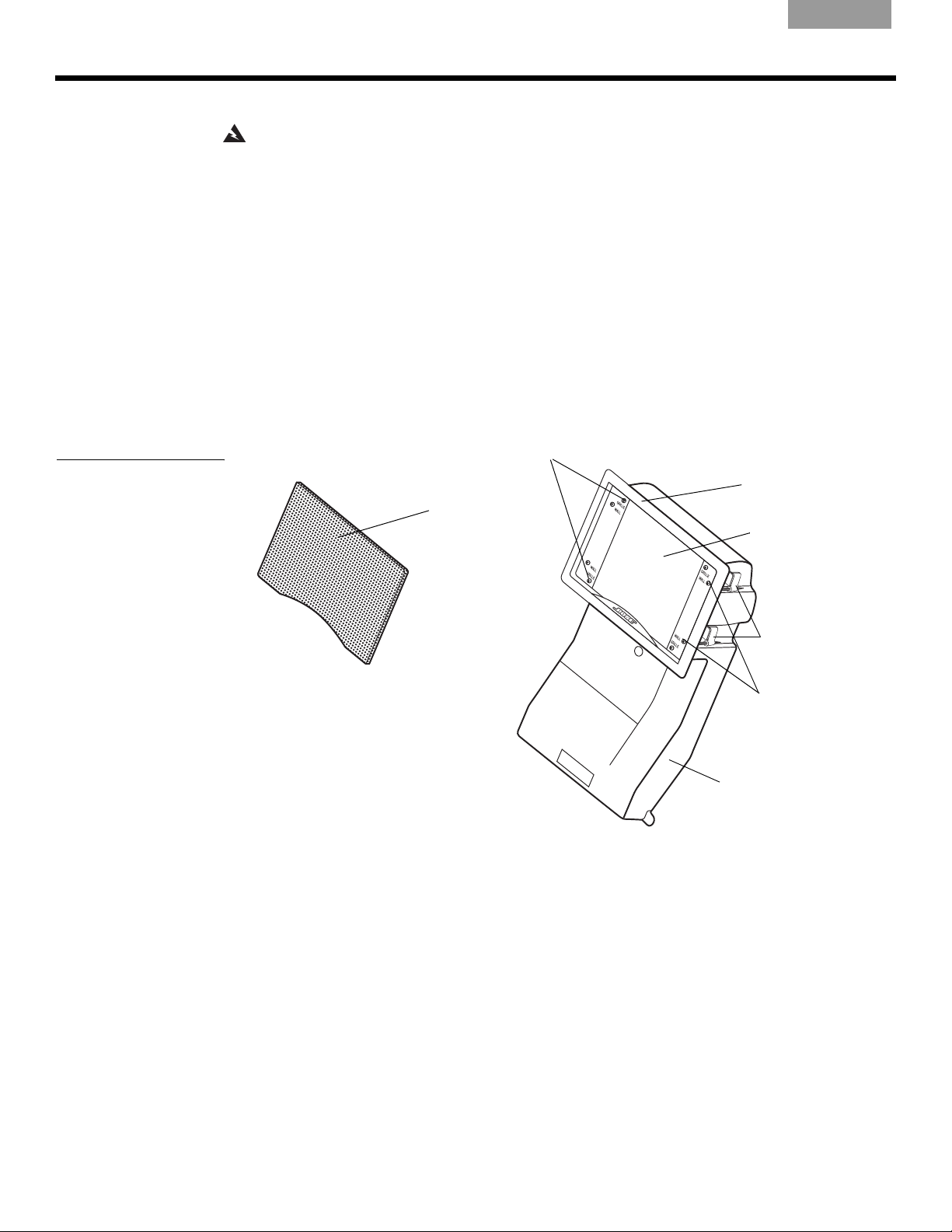
What makes this speaker better also makes it different
When installed, Virtually Invisible® 191 speakers take up very little wall space. What isn’t
apparent is their advanced speaker enclosure design, shown in Figure 1. It ensures
predictably fine performance wherever the speakers are installed, regardless of the size and
shape of the wall space. It also helps prevent the speaker sound from invading other rooms, a
common problem with installed speakers of more conventional design.
®
Virtually Invisible® 191 speakers. Innovative
EnglishFrançaisNederlands DeutschItaliano
Figure 1
Speaker enclosure with the
rectangular frame attached
Rectangular grille
Speaker frame screws
Rectangular
speaker frame
Speaker face
Dogleg clamps
Dogleg clamp
screws
Speaker enclosure
4
Page 5
English Français NederlandsDeutsch Italiano
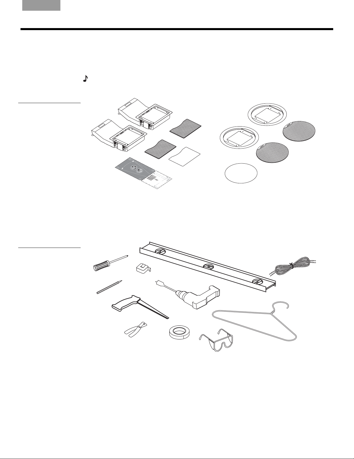
Unpacking
Carefully unpack the speakers. Check to be sure the carton includes all the parts shown in
Figure 2. If any part of the speaker pair appears damaged, do not use them. Notify Bose or
your authorized Bose dealer immediately. For Bose contact information, refer to the address
list included in the carton.
Note:
Now is a good time to find the serial numbers on the back of each speaker and copy the
numbers onto your warranty card and in the “For your records” space on page 2.
PREPARATION
Figure 2
Contents of the carton:
• 2 Speakers, rectangular
frames attached
• 2 Rectangular speaker
grilles
• 1 Rectangular paint shield
• 1 Template
• 2 Round speaker frames
• 2 Round speaker grilles
• 1 Circular paint shield
Figure 3
Items required to install the
speakers as instructed
Speakers
Rectangular
Round speaker
frames
speaker grilles
H
E
TA
RE
P
E
G
RA
C
U
YAREA
T
A
D
RO
O
U
N
N
O
G
R
C
A
UT
YA
A
R
D
R
E
O
O
A
U
N
N
OT
H
D
ERE
T
A
P
E
Template
D
T
G
R
C
AY
U
T
AR
AR
D
E
O
O
A
U
N
N
O
D
T
9
G
"
R
(
2
C
2
AYA
.
U
9cm
TAR
G
RA
YARE
T
A
ROU
A
N
O
D
T
)
R
14
D
C
E
O
O
U
D
ON
/
A
2
1
"(
U
N
36
N
O
.
9
D
T
c
m
H
)
ER
T
A
E
P
E
G
R
C
AY
U
TA
AR
G
RA
C
U
Y
T
A
A
RE
D
ROUN
ON
A
O
D
T
b
e
f
D
a
ROU
o
r
r
E
en
eyou
e
O
le
ot
A
h
c
az
t
r
s
i
p
for
ur
c
a
N
ro
alw
r
e,
d
d
c
W
N
s
r
e
c
illi
O
i
A
ed.
o
ri
c
n
on
n
ns
R
D
g
g,
N
.
T
u
c
D
I
ea
l
c
N
t
o
o
a
G
n
l
n
ed
pr
d
:
o
ui
M
tc
o
b
t
f
a
s
ehi
ess
u
k
t
or
es
t
n
h
A
io
r
d
pl
ure
o
na
um
t
ug
h
E
l
em
t
h
n
i
he
b
ns
g
su
i
yo
n
,
t
l
s
g
s
a
i
r
u
po
p
s
f
.
uch
l
ace
le
rof
p
h
I
t
r
f
r
are
oc
c
y
e
&
s
a
ho
ou
s
e
s
c
th
s
not
T
o
ed
s
i
on
at
n
en
r
su
du
a
.
h
a
s
n
c
av
li
i
ure
c
i
s
h
t
sl
o
s
n
s
e
n
a
s
o
s
a
,
a
t
c
s
r
u
a
c
f
e
ti
e
p
rf
G
e
on
ll
d
a
e
l
a
o
l
u
r
e
l
r
e
i
c
s
m
n
l
c
l
s
b
e
d
u
i
t
n
RA
YAR
R
E
O
A
U
N
D
T
H
E
T
RE
A
P
E
p
s
b
e
r
s
l
ta
i
g
be
o
c
i
C
f
n
o
t
.
W
t
a
hat
g
r
Don
h
ch
l
e
.
A
w
in
U
I
o
R
ha
f
ir
d
s
y
i
N
n
ot
th
e
o
v
g,
I
T
n
u
N
e
e
c
m
i
G
u
h
s
t
a
:
,
saf
t
z
A
M
h
a
r
a
e
o
r
ds
k
u
D
fo
e
g
r
h
su
ON
r
e
t
h
e
c
m
O
)
y
o
u
p
e
r
o
n
c
o
e
t
p
e
s
r
d
l
e
o
u
P
.
p
c
c
r
r
e
t
e
o
i
r
I
,
e
ic
lo
fe
f
c
d
y
a
s
o
e
h
.
o
l
s
n
l
t
a
u
e
w
i
s
v
o
c
c
i
u
a
e
o
n
r
t
r
i
l
r
n
a
n
i
t
t
h
e
c
s
h
c
l
g
a
a
a
r
n
e
i
s
,
z
l
o
c
n
a
o
a
a
w
h
u
s
f
t
le
r
o
ta
i
g
e
d
r
su
W
in
s
d
h
s
l
f
e
l
o
g
e
A
r
b
s
n
r
e
,c
r
u
e
RN
,
i
H
b
r
h
be
s
o
f
c
e
i
a
n
n
s
o
h
I
f
c
f
o
p
N
d
o
afefo
d
n
o
e
e
r
u
r
s
G:
r
m
o
t
s
e
l
e
i
n
u
h
t
f
e
s
.
e
o
th
lt
e
y
y
p
M
s
I
o
t
ou
m
p
o
u
f
rd
a
a
r
s
r
s
l
o
u
t
a
y
u
t
i
,
c
t
p
u
o
fe
i
k
co
o
m
r
h
o
n
s
p
l
r
n
il
e
u
u
e
u
a
n
g
r
s
c
l
a
b
m
n
o
i
a
,
c
v
s
d
.
s
n
o
a
l
i
d
c
ng
s
ha
eha
i
c
u
b
u
D
g
n
i
re
o
d
n
e
u
o
be
i
re
i
.
c
e
n
n
r
o
t
s
e
i
.I
n
s
i
t
D
e
le
g
a
a
l
n
s
t
s
d
l
n
s
a
h
W
a
h
th
i
t
.
l
o
o
o
z
n
.
f
i
c
u
l
o
o
i
l
az
o
i
l
a
t
r
n
e
g
t
yo
e
e
n
AR
l
n
t
r
n
r
t
s
r
s
d
p
d
.
r
s
i
o
c
d
sb
a
c
u
s
a
ur
u
l
D
t
t
u
u
th
s
a
b
r
p
a
r
N
n
ds
f
c
o
t
m
a
e
l
e
o
l
a
o
e
e
l
I
u
t
erb
r
w
,
h
t
N
c
n
l
h
t
b
m
e
i
t
o
s
c
i
c
e
i
ot
r
c
i
G
n
r
w
n
o
,
o
o
s
s
i
u
dt
n
s
g
n
:
su
u
n
e
a
c
t
u
t
g
s
.
M
g
c
f
f
h
u
t
r
h
e
o
,
u
WAR
5
h
I
c
e
h
e
a
t
f
a
e
r
l
h
r
f
a
t
t
e
t
o
y
o
t
k
m
s
hr
h
l
c
h
a
o
e
r
e
u
u
y
es
,
a
o
u
d
d
r
g
o
m
p
s
N
s
f
v
u
r
h
a
u
r
a
u
i
u
e
p
g
ll
o
I
c
r
r
N
c
in
)
o
pr
h
fe
e
e
e
h
t
G:
g.
W
s
s
o
s
n
t
c
a
h
u
cee
s
h
t
o
D
s
h
e
r
M
io
os
t
f
a
o
a
e
H
s
s
n
a
t
en
d.
c
l
p
u
a
k
e
h
e
r
o
li
e
c
a
e
s
I
t
t
n
ve
,
r
T
c
t
i
s
h
c
c
h
t
o
a
a
a
o
h
EC
t
n
l
s
ll
a
h
s
w
erb
e
z
u
a
n
i
a
r
lta
l
v
t
in
r
i
e
d
s
a
e
g
s
h
f
s
,
o
U
,
a
a
r
s
z
p
e
f
u
e
a
T
c
ro
yo
r
f
h
d
o
c
s
u
r
a
fe
ondu
OU
s
p
r
ss
el
o
c
e
e
c
i
e
t
o
ri
T
i
d
t
c
n
.
s
D
a
a
l
A
o
o
l
r
in
RE
n
pl
s
o
t
u
t
a
m
c
A
l
le
u
b
t
r
i
n
thr
g
,
o
u
g
h
H
E
T
R
A
E
PE
E
AR
T
U
O
T
U
C
E
T
5
I
p
r
o
H
c
/
f
2
1
o
e
n
s
"
c
s
d
o
W
io
u
n
(14
d
i
ce
n
r
ts
i
l
a
lin
W
a
l
o
l
i
g
r
e
n
A
.
p
d
s
R
D
l
t
u
w
b
a
NI
o
m
e
ll
i
r
er
n
h
W
N
in
b
o
i
in
G
n
g
A
t
b
d
,
c
g
:
R
e
u
c
.I
M
t
f
N
h
o
o
t
a
e
t
r
n
I
f
h
N
e
k
m
d
y
ro
e
G
u
o
,
ug
it
u
:
s
s
so
u
u
M
a
h
r
c
r
e
a
s
h
r
k
ur
t
p
a
e
h
l
f
s
e
u
ac
su
m
e
s
e
r
p
b
b
e
s
o
i
n
e
t
t
t
h
g
h
c
f
a
,
e
o
h
t
c
o
o
s
r
o
s
p
n
e
nc
e
o
c
n
t
e
y
cho
e
i
a
o
l
a
e
u
d
s
l
c
ed
e
b
p
n
est
eh
r
i
s
o
i
b
n
sa
d
ce
e
h
f
t
e
h
a
e
f
in
th
o
d
r
:
d
c
.
a
M
th
v
a
e
T
e
k
r
m
a
h
e
n
8
s
a
.
l
s
za
I
u
f
/
1
1
r
yo
rd
6
e
"
s
t
u
h
(
,
2
e
a
s
0
re
u
s
.
c
p
h
n
o
o
t
a
t
c
s
s
h
e
u
o
l
r
s
e
e
e
c
,
ni
tr
c
i
o
c
s
n
a
s
su
l
a
w
fe
ir
in
f
o
g
r
,
c
ut
t
i
n
g.
Rectangular
paint shield
H
E
TA
R
E
c
P
E
s
u
r
W
f
a
A
R
N
IN
G
Circular
paint shield
Round
speaker grilles
Other equipment you will need
Hardware for securing the speaker to a wall or ceiling comes attached to the speaker, but you
will need a variety of other equipment and tools to install the speakers (Figure 3).
Please refer to “Help for the beginning installer” on page 21 for additional information
on working with tools, materials, and other do-it-yourself information.
Phillips-head
screwdriver
Tape measure
Carpenter’s level*
Speaker cord**
Sharp pencil
Keyhole saw****
Half-inch spade bit
Power drill
Sturdy wire
(such as a coat hanger)
that is 22 in. long
Painter’s tape***
Wire cutter/stripper
Protective eyewear
* Carpenter’s level is suggested for use when installing speakers in a wall.
** Speaker cord specifications are provided in the Reference section of this guide.
*** Painter’s tape or other tape with light adhesive that will not damage paint or wallpaper.
**** Cutting tool – For drywall: a keyhole saw, drywall saw, rotary cutting tool, or jigsaw.
For plaster and lath: a saber saw or a rotary cutting tool.
5
Page 6
P
English&
ranslations
REPARATION
Deciding on speaker placement
The design of your new Virtually Invisible® 191 speakers makes them well-suited to either wall
or ceiling installation. The location you choose will affect the procedure for installing them.
Consider the options below, then follow the instructions that apply to your choices:
• How you will use the speakers?
• for stereo sound at the front of a room or seating arrangement, or
• as home theater front speakers or surround sound rear speakers
• What surface will you install them in?
• an interior wall (abutting another room), or exterior wall (abutting outside), or ceiling
• in finished (plaster and lath or wallboard), or new construction
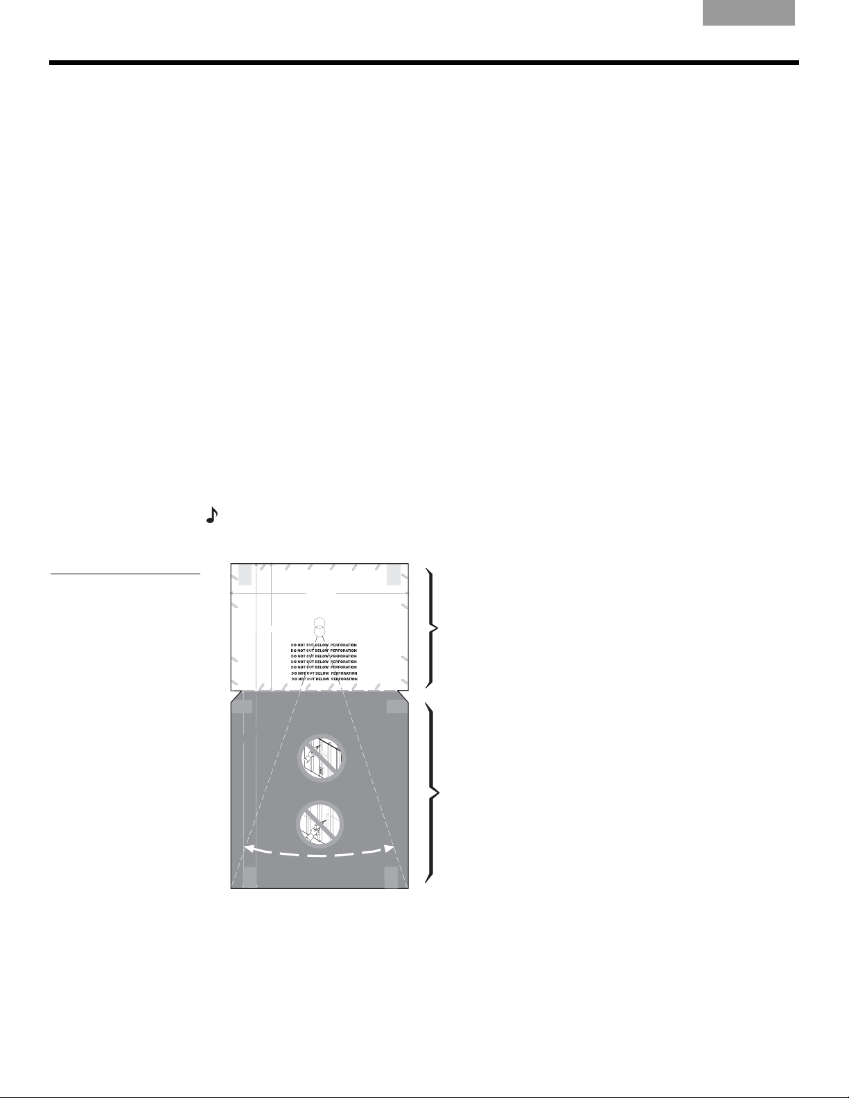
Three tips for determining speaker placement
1. The template can be placed against a wall or ceiling to help determine the amount of
space the speaker will need. Each speaker enclosure extends into the wall or ceiling, as
shown in the gray DO NOT CUT area on the template (Figure 4). In a wall, the speaker
may be inserted either up or down and will extend either above or below the grille.
2. Use of a stud finder can help ensure that the speaker hole is at least 4
a stud or joist.
3. All electrical wiring, vents and plumbing pipes located inside the walls must be avoided
(Figure 5 on page 7). Check with a trained professional to learn how to locate and avoid
them.
EnglishFrançaisNederlands DeutschItaliano
3
/4 in. (12 cm) from
Figure 4
Tem pl at e
Note:
To prevent problems with condensation in cold climates where a humidifier is used, avoid
inserting the speaker upside-down in an exterior wall.
TAPE
WARNING: Make sure the spot chosen is safe for cutting. Do not cut through
HERE
surfaces that have hazards, such as electrical wiring, conduits or plumbing,
concealed behind them. If you are not sure, consult a professional installer
before you proceed.
WARNING: Make sure the spot chosen is safe for cutting. Do not cut through surfaces that have hazards, such as electrical
wiring, conduits or plumbing, concealed behind them. If you are not sure, consult a professional installer before you proceed.
WARNING: Make sure the spot chosen is safe for
WHITE CUT OUT AREA
drilling. Do not cut through surfaces that have hazards
concealed behind them, such as electrical wiring,
conduits or plumbing. If you are not sure, consult a
professional installer before you proceed.
51/2" (14 cm)
WARNING: Make sure the
spot chosen is safe for
drilling. Do not cut through
surfaces that have hazards
concealed behind them,
such as electrical wiring,
conduits or plumbing. If you
are not sure, consult a
professional installer before
you proceed.
WARNING: Make sure the spot chosen is safe
for drilling. Do not cut through surfaces that have
hazards concealed behind them, such as
electrical wiring, conduits or plumbing. If you
are not sure, consult a professional installer
before you proceed.
DO NOT
TAPE
HERE
CUT AROUND
GRAY AREA
141/2" (36.9 cm)
9" (22.9 cm)
CUT AROUND
GRAY AREA
DO NOT
CUT AROUND
GRAY AREA
DO NOT
TAPE
CUT AROUND
HERE
GRAY AREA
DO NOT
81/16" (20.5 cm)
Translations below
WARNING: Make sure the spot chosen is safe for
drilling. Do not cut through surfaces that have hazards
concealed behind them, such as electrical wiring,
conduits or plumbing. If you are not sure, consult a
professional installer before you proceed.
Pilot Hole
English &
Translations
CUT AROUND
CUT AROUND
WARNING: Make
sure the spot chosen
is safe for drilling. Do
not cut through
surfaces that have
hazards concealed
behind them, such
as electrical wiring,
conduits or
plumbing. If you are
not sure, consult a
professional installer
before you proceed.
WARNING: Make sure the spot
chosen is safe for drilling. Do not cut
through surfaces that have hazards
concealed behind them, such as
electrical wiring, conduits or plumbing.
If you are not sure, consult a
professional installer before you
proceed.
DO NOT
GRAY AREA
DO NOT
CUT AROUND
GRAY AREA
DO NOT
CUT AROUND
GRAY AREA
DO NOT
GRAY AREA
TAPE
HERE
WHITE CUT OUT AREA
TAPE
HERE
TAPE
HERE
FOR CUTTING
Large white area
represents what to cut
out for the speaker face.
NOT FOR CUTTING
Large gray area
represents space to
reserve behind the wall
for the speaker
enclosure.
6
Page 7
English Français NederlandsDeutsch Italiano
P
REPARATION
Figure 5
Cautions against unseen
danger, such as (a) electrical wires or (b) plumbing
pipes, behind the wallboard
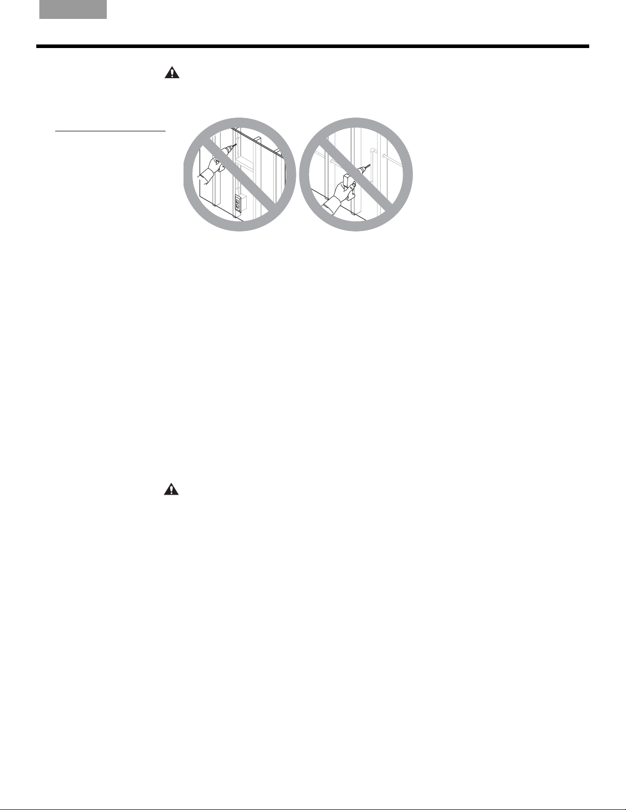
CAUTION:
When installed, the speaker enclosure cannot be seen behind the wall or ceiling. Do
not attempt to nail, cut, or drill on that surface area. Puncturing the speaker enclosure with a tool
will seriously damage the speaker.
(a)
(b)
Consider which shape you prefer for your speakers
You have a choice of a rectangular or round speaker face – the part that is visible when the
speaker is installed. Consider which shape will work best in the location you choose for the
speakers. Typically, the rectangular shape is best suited for walls and the round shape is best
suited for ceilings.
It is easy to remove the rectangular frames and replace them with round frames. You can do it
now or wait until you know for sure where each speaker will fit. However, be sure to make
that change before you insert either speaker into the wall or ceiling. The lip of the
speaker frame prevents the speaker from slipping behind the wall and out of reach. Do not
remove the frame while the speaker is in the wall. See
frames” on page 15 for instructions for removing and replacing speaker frames.
“Reorienting or changing speaker
Considering your wall type and the approach it requires
If you are installing the speakers in a pre-wired room of finished construction with 2 x 4 stud
walls covered with wallboard, the placement of your speakers has already been determined.
Please refer to “Steps to Installing” on page 9. These instructions cover installation of the
speakers, with either a rectangular or round grille, in a wall or ceiling.
If your installation is different, use the information below to help determine where to place
your speakers. As you decide where you want each speaker grille, use the guidelines below:
CAUTION:
Do not install near any heat sources, such as halogen lamps, registers, stoves, or
other apparatus (including amplifiers) that produce heat.
For placement in walls
• The two speakers should be a minimum of 5 ft. (1.5 m) apart.
• For in-wall speakers providing stereo at the front of the room or home theater surround
sound from the rear, install so each speaker grille is 4 to 6 ft. (1.2 to 1.8 m) from the floor for
best performance.
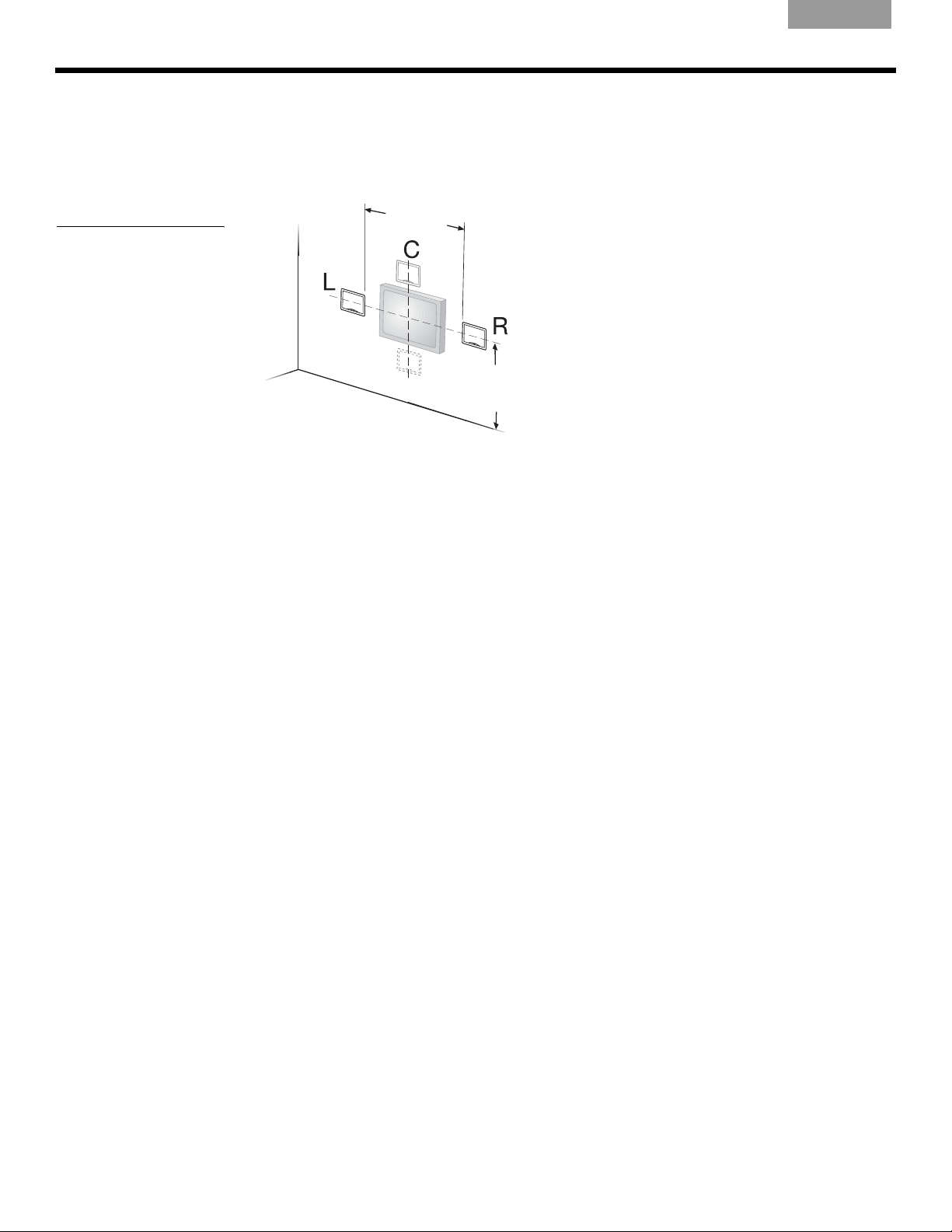
• For in-wall home theater front speakers, install the pair horizontally aligned with the center
of the video screen (Figure 6 on page 8).
7
Page 8
P
REPARATION
EnglishFrançaisNederlands DeutschItaliano
• Place the in-wall center channel speaker above or below the video screen, centered
between, but not on horizontal center with, the left and right front speakers. If a line were
drawn between the left, center, and right front speakers a “V” shape would be created.
• The speakers should not be installed sideways in a wall; the enclosure should be either
above or below the speaker face.
Figure 6
Orienting wall speakers for
front home theater use
5ft.
(1.5m)
4 - 6 ft.
(1.2 - 1.8 m)
For placement in ceilings
When placing the speakers in the ceiling, please use the following guidelines. The direction
the enclosures face will be determined by the spacing of the ceiling joists. The speaker
enclosures should be parallel to the ceiling joists.
For best in-ceiling stereo performance:
• the speakers should each be placed an equal distance on either side of the primary
listening area.
For best in-ceiling home theater performance:
• Place the right and left front speakers at equal distances to the right and left above the
video screen.
• Place the center speaker above the center of the video screen.
• Place the surround speakers opposite the video screen wall, evenly spaced.
8
Page 9
English Français NederlandsDeutsch Italiano
Before you make any holes
Be sure you have read and understand the considerations provided in “Preparation” starting
on page 5, so you can proceed with confidence.
STEPS TO INSTALLING
CAUTION:
If you are unsure of your ability to complete this process, contact a professional
installer.
Small check marks call your attention to the tools you’ll need for the next step.
Tips offer ideas to make the job go easier and help you avoid mistakes.
Drill a pilot hole for testing the wall space
Before you make a large cut into the wallboard, check the space by probing behind the wall
or ceiling through a small pilot hole. Time spent now can help ensure a successful installation.
Note:
behind a pilot hole. You may prefer to eliminate this step and skip ahead to “Prepare the wall for
inserting the speaker” on page 13. Do this only if you can be sure the insulation is malleable and
that nothing else behind the wall will impede the installation.
WARNING:
do not drill or cut into that wall. Find a different location for the speakers instead.
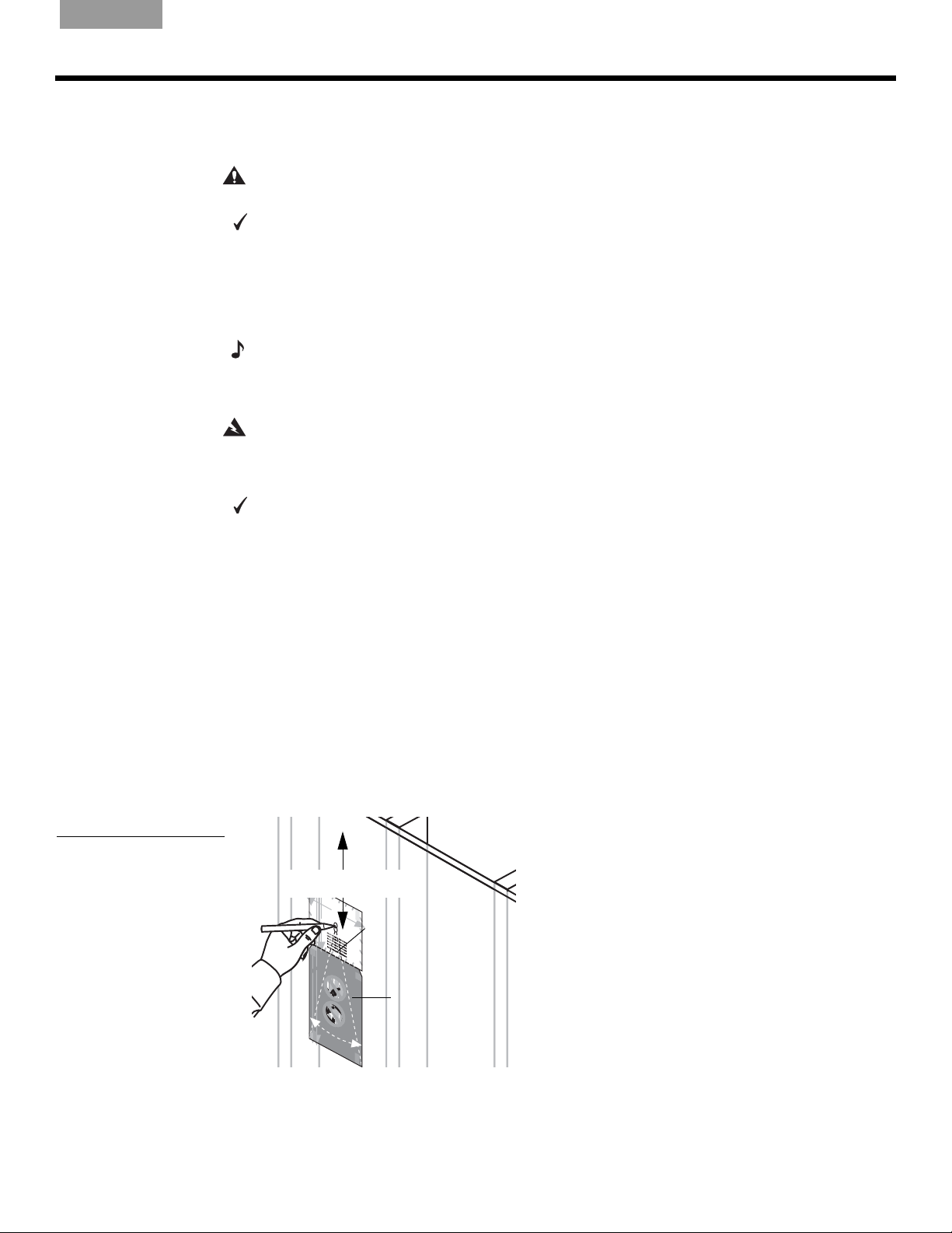
Using the template
You will need a sharp pencil for this step.
The template shows where to drill two
large enough for the entire speaker. You can then test the space behind the hole to make sure
there is enough room for the speaker and that there are no materials blocking the installation.
Notice the dotted lines extending at an angle from the pilot hole to the bottom corners of
the DO NOT CUT area on the template. Use them as a guideline to be sure there is enough
room below the pilot hole for the length and width of the speaker enclosure.
To position the template
1. Select a spot on the wall or ceiling where you want the center of the speaker grille. Allow
2. Center the pilot-hole circles on the selected spot as you press the template to the wall.
3. Use a pencil to trace around the inside of the circles (Figure 7).
4. Remove the template.
If you are working in an exterior wall where there is insulation, it may be difficult to probe
If you believe the insulation behind the wall may be composed of asbestos,
enough space for the speaker enclosure both above and below the pilot hole. You may
need that second option if you find an impediment in the space below the hole.
1
/2 in. (13 mm) pilot holes before you make an opening
Figure 7
Preparing to cut a pilot hole
At least 9" (22.9 cm)
T
AP
E
H
E
R
E
WA
R
N
s
ING:
urfa
ces
Make
c
on
tha
ce
s
t
ale
ur
befo
h
e
ave
d
th
be
re
h
e
y
h
az
s
ind
po
ou
ard
t
pro
th
ch
s
em
,
o
c
su
s
ee
. If
e
c
n
d
h
WHITE CUT OUT AREA
is sa
.
y
a
ou
s
e
are
fe
le
W
fo
ctr
A
not
R
N
r
ic
IN
w
c
a
ir
G
ut
i
su
l
n
:
g,
M
w
ti
re,
c
ng.
a
iring,
o
k
n
e
d
s
c
u
u
D
i
o
t
r
s
W
e
nsu
o
o
t
co
1
A
8
h
r
R
n
e
p
nduits
s
N
l
o
u
d
/
lt
IN
po
m
r
t
il
li
G
b
a
t
c
n
"
i
c
:
n
g
1
u
M
h
p
g
.
6
(20
co
o
t th
D
,
r
a
s
c
o
ofe
or
ke
n
e
o
c
n
n
n
.5
ea
ot
r
s
c
i
s
oug
plu
e
u
T
c
ssion
c
l
r
a
T
e
s
o
r
u
c
e
a
a
l
d
n
ed
A
t
n
th
f
m
t
d
e
b
s
h
mb
P
u
l
h
e
e
r
ati
be
fo
i
o
)
h
t
p
E
s
s
u
r
i
o
r
h
a
n
p
o
c
g
ing
n
o
i
d
o
h
n
s
l in
u
f
r
t
e
t
H
d
t
s
p
he
t
b
s
c
u
i
l
th
s
e
n
h
E
u
,
r
l
i
g
o
m
f
stall
m
o
o
e
a
R
.
s
w
n
m
c
,
b
e
D
s
a
e
i
E
n
. I
n
l i
o
s
u
g
i
f
ch
n
th
n
s
er
.
y
s
s
o
at
o
a
t
If
t
a
a
c
u
y
s
ha
l
f
l
e
u
e
a
o
e
fo
t
r
r
v
u
l
e
e
e
t
b
h
n
a
r
c
e
h
r
r
tr
o
fo
o
az
e
i
u
1
t
c
5
r
n
g
a
s
a
e
o
h
u
rd
l
y
t
r
w
s
s
s
o
e
/
i
u
u
,
u
r
i
r
c
r
"
ng
fa
p
e
o
r
, c
c
2
n
o
,
(
e
s
1
c
o
s
u
e
4
n
l
e
t
t
s
h
d
a
u
a
cm
.
l
t h
p
t
r
a
o
a
f
W
v
)
e
e
s
A
W
s
h
R
i
A
o
az
NI
n
R
d
a
a
N
r
N
r
l
i
s
I
d
l
i
N
G
l
n
p
i
s
n
G
o
s
:
,
g
t
t
:
M
s
a
.D
M
c
co
u
l
h
a
l
c
e
a
o
k
o
d
n
h
P
r
k
s
e
ri
c
n
e
e
b
a
l
e
l
s
i
n
o
i
e
s
ng
s
a
l
u
t
u
f
co
i
l
o
o
s
e
r
e
c
r
.
e
e
r
l
u
d
s
D
su
n
e
e
t
af
t
tt
t
d
c
o
h
be
h
y
r
t
e
u
Pilot hole
e
h
f
e
r
n
o
ace
i
i
r
f
hi
ot
t
ca
u
p
o
o
s
s
r
r
n
p
u
p
c
o
or
l
s
c
d
o
g
u
r
f
o
t
o
h
e
t c
t
h
t
n
t
p
c
h
s
at
h
c
s
l
e
s
h
e
u
e
ro
u
i
e
o
h
m
m
o
a
rfa
u
d
ave
s
l
n
s
e
,
b
g
e
.
u
a
d b
c
s
H
i
h
n
n
c
l
e
u
h
h
g
i
s
is
c
n
e
a
o
.
a
h
s
h
t
z
I
s
h
s
a
t
i
f y
a
n
l
c
a
a
a
e
r
e
o
d
s
l
fe
d
t
l
l
ou
n
e
e
s
t
h
e
d
he
f
ct
r
a
l
b
u
o
e
ric
a
v
i
m
r
t
ct
e
r
s
e
a
a
e
,
fo
r
o
re
l w
h
n
i
r
c
r
a
pl
a
e
o
n
i
z
ri
l
t
o
u
a
w
y
n
m
t
su
r
o
g
s
p
d
i
u p
,
b
ri
u
r
s
re
in
o
n
r
e,
f
g
g
,
es
r
.
o
,
co
co
s
ce
I
f
io
y
n
n
y
o
e
n
s
o
s
WA
u
ali
u
d
u
u
l
l
.
p
t
t
ns
RN
r
a
a
o
W
c
tal
f
e
I
o
NG
A
e
l
e
r
d
R
d
r
.
:
ri
b
N
ll
M
e
i
I
s
n
f
N
o
a
h
u
g.
r
k
a
G
r
e
e
e
z
D
:
a
th
su
o
M
r
ds
e
n
i
r
a
s
e
o
el
s
k
s
t
c
p
t
c
e
e
h
af
on
o
c
e
u
t
t
e
t
ric
cea
sp
ch
th
f
n
o
al
r
ar
o
o
o
r d
o
l
t
s
t
ed
u
w
e
c
e
c
gh
r
no
h
ir
i
n
u
l
o
b
i
l
n
i
t
n
s
e
s
s
t
g
t
s
e
g.
u
h
be
h
u
,
n
rf
i
u
r
r
c
n
o
f
a
D
f
r
i
o
d
a
s
o
e
c
u
o
n
c
r
,
e
t
s
g
e
d
h
es
co
s
a
h
h
u
em
y
fe
th
a
i
o
ns
t
th
s
z
a
u
,
a
t
u
or
a
s
p
h
r
l
t
u
t
d
r
a
pl
oc
c
h
a
b
s
v
h
a
u
e
e
p
c
e
v
m
a
h
r
o
e
e
o
s
in
bi
n
d
fe
.
c
d
n
s
e
t
g
a
s
al
h
.
s
i
o
e
e
I
e
n
f
m
d
l
al
y
ec
,
ou
s
i
n
c
t
r
u
o
s
i
c
t
c
n
al
al
h
d
le
u
w
r
i
t
p
ir
s
l
i
u
n
o
m
g
r
,
b
i
n
n
g
o
.
t
su
I
f
y
r
o
e
p
u
r
,
o
a
c
f
o
e
re
n
s
s
s
b
i
u
on
e
l
t
f
o
a
a
r
li
ey
n
s
o
t
a
u
l
le
T
p
r
r
A
oc
W
WHITE CUT OUT AREA
P
e
A
e
E
R
d
N
.
c
I
H
h
N
os
G
E
e
:
R
n
M
th
i
E
a
s
r
k
s
o
e
u
a
g
su
fe
h
c
D
r
f
o
s
or
e
n
u
t
c
rf
h
d
O
e
a
e
r
a
i
c
l
e
l
s
le
i
e
n
le
p
N
s
d
g
o
c
t
.
t
t
b
ha
r
D
i
e
c
o
h
a
O
t
If
C
i
l
h
n
n
y
w
a
o
d
o
i
v
t
T
r
U
u
t
in
e
c
h
u
a
g
e
ha
p
t
r
,
m
T
e
ro
c
z
,
o
n
f
a
s
n
e
o
r
u
d
s
d
A
t
c
u
s
s
s
p
h
i
i
t
o
u
ro
s
R
n
a
r
e
o
c
a
s
r
,
e
l
i
p
c
e
O
n
lu
o
d
E
s
n
.
m
t
s
n
a
U
G
b
u
l
g
le
i
l
n
t
l
r
g
is
a
N
R
.
b
h
e
fo
D
A
&
r
e
T
Y
y
r
ans
o
u
A
l
at
R
i
on
E
s
A
1
1
4
/
D
"
O
2
(
3
6
N
.
9
9
"
O
C
c
(
m
2
T
U
2
)
.
9
T
c
m
A
)
R
O
U
G
N
R
D
A
T
Y
A
P
A
E
R
H
E
E
R
A
E
D
O
N
O
C
T
U
T
A
R
O
U
G
N
R
D
A
Y
A
R
E
A
D
O
N
O
C
T
U
T
A
R
O
U
G
N
R
D
A
Y
Template
A
R
E
A
D
O
N
O
C
T
U
T
A
R
O
U
G
N
R
D
A
Y
A
R
E
A
D
O
N
O
C
T
U
T
A
R
O
U
G
N
R
D
A
Y
A
R
E
A
D
O
N
O
T
C
A
T
P
U
E
T
H
E
A
R
R
E
O
U
G
N
R
D
A
Y
A
R
E
A
D
O
N
O
C
T
U
T
A
R
O
U
G
N
R
D
A
Y
A
R
E
A
T
A
P
E
H
E
R
E
9
Page 10
S
TEPS TO INSTALLING
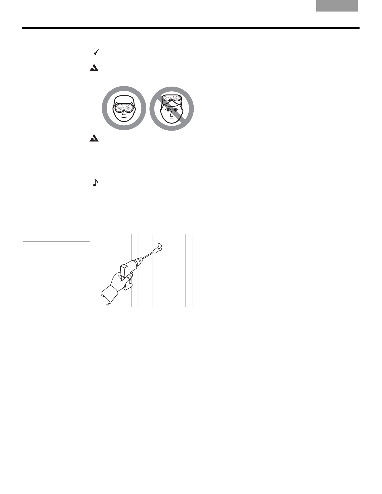
Figure 8
Caution against drilling
without eye protection
EnglishFrançaisNederlands DeutschItaliano
Drilling the pilot hole
You will need a half-inch spade bit and power drill, or a special rotary cutting tool for this
step.
WARNING:
or cutting tool (Figure 8).
WARNING: Make sure the spot chosen is safe for cutting. Do not cut through surfaces that may
have hazards such as electrical wiring, conduits, or plumbing concealed behind them. Follow all
other safety precautions.
1. Center the tip of the drill bit in the top circle you have drawn.
2. Drill completely through the wallboard to create a hole that you can probe behind.
Use eye protection and be sure to observe all safety precautions while using a drill
Figure 9
Using a spade bit with a
power drill to create the
pilot hole
Note:
If you encounter insulation in the wall, it will be difficult, or impossible, to probe behind the
pilot hole. If you are certain that your chosen location is free of hazards and impediments, you
may choose to cut the hole for the speaker anyway, remove some of the malleable insulation, and
proceed from there. Refer to “Prepare the wall for inserting the speaker” on page 13.
3. Drill the second hole just below the first one (Figure 9). This elongates the hole to allow
for testing the space for the length of the speaker enclosure.
10
Page 11
English Français NederlandsDeutsch Italiano
Testing the space behind the hole
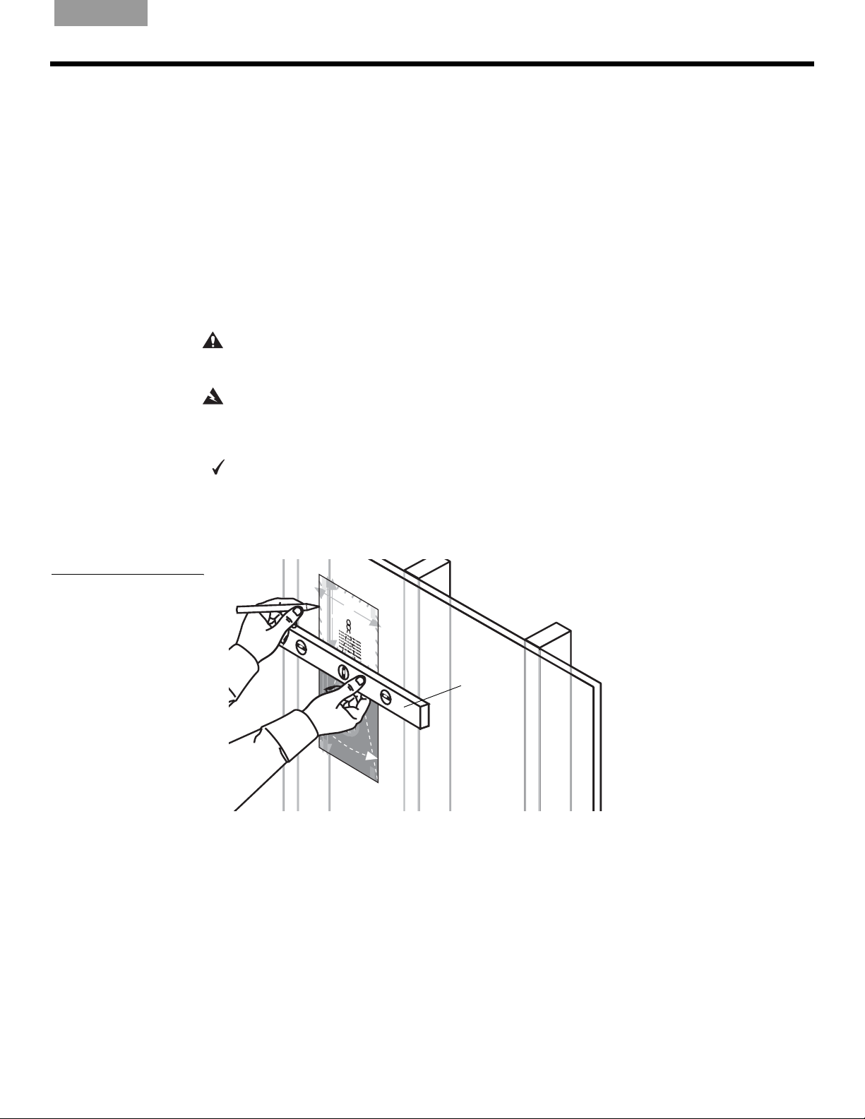
7LSYou need a tape measure and a sturdy wire (such as a straightened coat hanger)
22 in. (55.9 cm) in length for this step.
1. Bend the wire as shown in Figure 10.
Figure 10
A 22-inch (55.9 cm) length
of sturdy wire bent in two
places
7LSFor greater accuracy, make the first bend a little long, measure again, and cut off the extra
length at that end.
WARNING:
the wire with electrical tape to prevent electric shock.
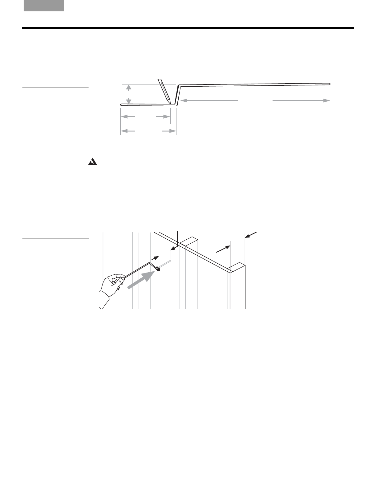
2. Make a mark 4
3. Use the bent wire to test for enough depth, front-to-back:
3 in. (7.6 cm)
1
4
/
in.
8
(10.5 cm)
3
/
in.
4
4
(12 cm)
If there is any possibility of electrical wiring in the space behind the wallboard, wrap
front-to-back depth of the hole.
Insert the short end of the wire into the hole and straight back (Figure 11). Probe to make
sure nothing is in the way to a depth of 4
behind the wallboard is deep enough for the front-to-back speaker dimension.
S
TEPS TO INSTALLING
1
14
/
in.
4
(36.2 cm)
1
/8 in. (10.5 cm) from the short end as an indicator of the proper
1
/8 in. (10.5 cm). This indicates that the space
Figure 11
Checking the space for the
depth of the speaker
1
"
/
8
4
)
m
c
1
"
/
8
4
)
m
c
5
.
0
1
(
5
.
0
1
(
• If the wire goes in without a problem, proceed to step 4, below.
• If you cannot insert the wire to the 4
1
/8-inch (10.5 cm) mark, you need to drill a new pilot
hole elsewhere. Then repeat step 3.
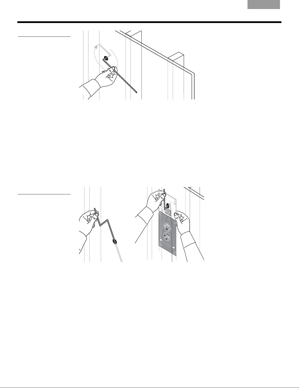
4. Use the wire again to test the width, side-to-side:
With the short end still in the hole, reposition it, as shown in Figure 12 on page 12, and
rotate it 360° around the hole. This indicates if the wall space is wide enough on each
side of the hole for the side-to-side dimension of the speaker.
11
Page 12
S
TEPS TO INSTALLING
Figure 12
Checking the space for the
width of the speaker
EnglishFrançaisNederlands DeutschItaliano
360°
• If the wire goes around the 360° arc without a problem, proceed to step 5 below.
• If you cannot rotate the wire all the way around up to the first bend, you need to drill a
new pilot hole elsewhere. Then repeat the preceding steps 3 and 4.
5. Use the bent wire to check for enough length below the hole:
Holding the short end of the wire, insert the long end into the wall or ceiling and straight
down from the hole (Figure 13a).
Figure 13
Inserting the long end of the
wire (a) and sweeping from
side to side to check the
length (b)
7LSYou may want to use the template for this step, as shown in Figure 13b.
• With the long end of the wire still in the hole, sweep it from side to side in a curve as
shown on the template. This indicates if the wall or ceiling space is long enough and
wide enough at the far end.
7LSWhen testing for length, move the wire near the wall or ceiling, then farther back from it
(as in Figure 13a, below).
(a)
(b)
9"
T
A
PE
HE
R
WHITE CUT OUT AREA
W
A
R
N
fo
r
d
r
ill
in
h
a
z
a
r
d
s
e
l
e
c
t
r
i
c
a
a
r
e
no
t
b
e
for
e
y
T
A
PE
H
E
R
E
1
4
(22
.9
c
T
A
H
E
W
A
R
N
s
I
N
u
G
r
f
ac
:
M
e
co
a
st
k
n
e
h
ce
a
s
t
u
a
b
hav
r
le
e
e
d
fo
t
e
h
b
r
e
e
eh
h
a
s
y
i
p
z
o
n
a
o
u
d
r
t
d
p
t
c
h
s,
ro
h
e
o
c
m
s
s
e
u
e
.
e
ch
nis
I
d
f
.
y
a
o
s
s
u
a
e
a
f
le
e
W
re
ct
A
f
o
R
no
r
NI
r
ic
w
c
N
t
a
i
r
G
u
i
s
lw
n
:
tt
g,
u
M
in
r
co
ir
ak
e
g
i
nd
,
e s
n
.
co
g
ui
D
u
,
t
r
W
s
e
o
n
con
1
o
A
t
8
s
h
r
RN
no
e
u
p
l
s
d
u
lt
/
d
I
po
r
m
t
NG:
i
l
u
li
a
b
cu
tc
n
"
i
i
g
n
1
t
M
p
h
.
s
g,
6
(
co
t
ose
D
2
r
a
c
th
o
o
or
n
k
0
on
esu
c
n
fe
n
.5
e
ro
o
c
i
al
p
t
s
e
Tr
s
c
c
TAP
e
re
a
u
l
o
s
c
u
s
u
a
db
led b
af
n
t
n
g
io
m
t
du
m
t
s
he s
e
h
h
l
e
a
r
n
f
it
o
)
t
h
b
o
p
E
eh
i
s
u
o
in
a
r
ro
p
in
g
c
n
o
d
in
o
lin
h
s
f
rpl
ut
e
HE
t
g
d
t
s
s
b
h
c
t
u
i
,
s
e
t
e
h
u
ng
h
r
l
s
io
m,su
o
f
m
o
e
ac
R
s
w
t
.D
na
m
b
a
e
e
E
i
n
n
.I
l
s
lle
o
g
i
c
i
n
f y
t
s
n
.
h
h
st
ot
a
r
s
as
ou
I
a
f
t
a
l
ha
c
y
f
le
e
u
ou
a
elec
r
v
tt
r
f
e n
o
e
b
a
hr
r
efor
h
r
t
o
e
o
r
az
1
ic
ug
ts
5
no
ey
a
a
r
ur
l
h
d
t
w
o
/
s
s
s
e
i
up
ur
ure
r
,
i
"
ng
c
f
o
a
(
ro
,
2
n
c
,
c
1
es
c
su
o
e
4
ns
th
ed
l
t
a
u
c
a
.
l
ta
pr
t
m
hav
of
W
)
e
e
s
ARN
WA
s
h
i
o
a
R
n
d
z
I
NI
al
a
r
N
il
s
rd
l
N
G
p
i
i
ng.
n
s
G
o
:
s
M
,
t c
:
t
s
c
all
M
D
h
uc
o
a
o
a
dr
o
n
e
ke
P
s
k
h
no
c
r
i
e
e
ll
ea
s
b
as
i
i
s
n
n
efo
l
u
t
c
u
g
i
le
o
s
r
c
o
r
.
e
e
e
u
d
s
D
s
nd
r
le
t
a
e
t
u
th
t
o
be
he
f
c
rf
t
ui
e
n
e
y
h
t
a
r
o
ro
h
f
t
o
s
p
c
ica
o
s
u
t
i
es
r
r
n
o
u
p
o
c
c
pr
d
g
o
l
u
th
f
o
r
e
h
t
t th
n
t
oc
p
ss
he
ch
at
c
s
l
u
e
r
e
u
i
o
h
m
o
m
o
a
rf
e
u
av
s
l
n
s
e
d
a
,s
bin
g
en
u
a
dbe
H
.
c
e
h
c
l
es
u
h
ha
g.
i
c
i
n
o
s
a
h
s
h
t
z
I
s
h
s
t
i
f
a
l
c
n
a
a
y
a
a
e
o
e
rd
d
s
l
f
t
l
l
o
nd
e
e
e
h
e
s
t
u a
h
c
r
f
a
u
le
t
em
o
r
be
i
ve
ic
t
c
r
s
r
a
al
e
t
,
fo
o
r
r
h
e
ic
r
n
w
re
az
p
al
no
o
i
r
l
u
t
in
a
y
t
w
mb
s
ou
g
r
s
p
ur
d
i
,
ur
r
ro
s
i
in
e
n
p
e
fe
g
,c
g
r
,
.
s
oc
,
c
sio
I
on
o
f
y
e
n
y
o
n
e
s
o
s
u
a
ul
u
d
ul
l
p
.
t a
t
i
n
ro
a
s
W
ce
ta
I
N
AR
ll
e
e
G
d.
rbe
:
NI
M
s
fo
N
u
a
g
r
k
r
G:M
.
e
e t
D
e
s
o
h
u
e s
n
i
r
a
s
e
o
k
s
t
c
po
t
e
he
a
c
on
ut
f
t
e f
c
c
s
t
e
n
h
p
ho
or
a
r
o
o
o
lw
l
t
t
s
ed
dr
u
cu
c
e
g
i
h
i
n
r
l
h
i
be
os
li
n
t
n
s
s
g
t
g
en
h
u
u
h
s
,
c
.
rfac
in
u
r
r
f
oug
D
is
r
o
a
d
e,
o
n
c
e
t
s
c
du
e
h
s
af
h
h
e
s
o
az
t
i
e
t
m
o
ns
h
t
sorp
ha
u
a
,
ar
ul
t
s
p
h
t
ds
u
t
ro
a
a
ha
c
beh
v
c
l
h
u
e
p
c
e
v
m
a
r
on
e
e
o
in
s
d.
b
f
e
c
i
d
n
ss
ea
as
g
t
h
.
i
o
l
e
em
ed
If
n
y
le
al
,
o
c
i
s
c
u
n
t
ri
uc
ondu
st
cal
a
h
l
l
e
wi
it
r
p
s
r
l
or
i
u
n
mbi
g
,
n
n
g.I
ot
su
f
y
r
o
pr
e
u
,
o
c
are
fes
o
ns
s
befor
i
u
o
l
n
t
a
a
l
e
i
n
y
s
o
t
a
u
l
l
e
p
r
r
o
W
WHITE CUT OUT AREA
c
e
A
e
R
d.
N
c
I
h
N
os
G
en
:M
t
h
i
a
ss
r
ke s
oug
a
f
e
h
ur
c
D
f
once
su
o
e
r
t
r
d
h
O
fa
r
e
aled
i
c
l
e
l
s
e
i
le
n
p
s
g
c
o
N
th
.
t
b
t
r
D
i
e
atha
c
o
h
a
O
If
C
i
l
n
n
y
w
d
o
o
i
v
T
t c
r
U
u
th
i
e
n
a
u
g,co
e
h
p
re
t
m
T
a
r
o
z
,
n
f
ar
e
n
su
o
s
d
d
A
t
s
u
c
s
p
s
iona
h
its
u
r
o
R
r
a
e
c
o
s
e
,c
r
l
e
p
O
in
o
l
d
u
E
s
ns
.
m
t
ng
a
G
U
b
u
lle
in
l
t
l
r
ish
g
a
R
N
b
.
e
f
A
&
D
o
re
T
Y
y
r
a
o
u
ns
A
l
a
R
t
io
n
EA
s
1
/
D
"
O
(
2
36
N
.9
c
O
C
m
T
U
)
T
m
A
)
R
O
GR
U
N
A
D
TA
Y
P
A
E
R
HE
EA
R
E
D
O
N
O
C
T
U
T
A
RO
G
U
R
N
A
D
Y
A
R
E
A
D
O
N
O
C
T
U
T
A
R
O
G
U
R
N
A
D
Y
A
R
E
A
D
O
N
O
C
T
U
T
A
R
O
G
U
R
N
A
D
Y
A
RE
A
D
O
NO
C
T
U
T
A
R
O
G
U
N
R
A
D
Y
AR
E
A
D
O
N
O
C
P
T
U
E
T
E
A
RE
R
OU
G
R
N
A
D
Y
A
R
E
A
D
O
N
O
C
T
U
T
A
R
O
G
U
R
N
A
D
Y
A
R
E
A
T
A
PE
H
E
R
E
• If the wire goes in and sweeps from side to side at the far end without a problem, proceed
to the next major step: “Prepare the wall for inserting the speaker” on page 13.
• If you find an impediment below the pilot hole, and you are working in an interior wall,
insert the wire upward. If there are no impediments above the pilot hole, you can install the
speaker upside-down. If you are working in an exterior wall, installing the speaker
upside-down is not recommended. In this case, if you find an impediment you need to drill
a new pilot hole elsewhere. Then repeat the preceding steps 3, 4, and 5.
12
Page 13
English Français NederlandsDeutsch Italiano
Passing the pilot hole test
If you have successfully determined that this location will work for one speaker, test the wall
or ceiling for the second speaker before making any larger holes. Refer to “Drill a pilot hole for
testing the wall space” on page 9 and repeat those steps.
If the first speaker location is fine, but the second is not, you may want to relocate both
speakers.
Repairing a pilot hole
To patch a pilot hole, fill it with spackle. Let the spackle dry, then add more until the hole is
slightly overfilled. When it is thoroughly dry, sand the area to make it flush with the wall.
Prepare the wall for inserting the speaker
Use care in the steps that follow to ensure satisfaction with the end result.
CAUTION:
about cutting into or running cord behind the wall, it is best to stop here. Contact a professional
installer, describe the job, and request a cost estimate before engaging the installer’s services.
WARNING:
a different location for installing the speakers instead.
Now is a good time to reconsider your comfort level with this job. If you have doubts
If you believe insulation in a wall may contain asbestos, do not cut into the wall. Find
S
TEPS TO INSTALLING
Figure 14
Making sure the template is
straight
Measure and mark the hole to be cut
You need a carpenter’s level, a sharp pencil, and optional tape with the template to
complete this step.
1. Position the template carefully over the pilot hole where you want to install one speaker.
2. Make sure the template is level (Figure 14).
T
A
P
E
H
E
R
E
WA
R
N
s
IN
u
rf
G
ac
:M
co
es
a
n
that
k
cea
e
su
b
led
efor
h
r
av
e
beh
e
e
t
he s
haza
y
o
ind
u
po
p
th
rds
r
t
oc
c
em. If
,
hos
su
e
WHITE CUT OUT AREA
ed.
c
e
h
n
y
ou
a
is
W
s
s
A
e
a
R
a
NIN
le
r
w
fe
e
ir
c
i
G
n
no
t
f
g
:
r
or
,
ic
Ma
c
t
c
o
al
k
s
nd
e
uttin
ur
s
u
w
W
it
u
e,
s
r
i
A
e
r
o
i
R
t
ng,c
g.
r
hes
c
N
dri
p
on
I
1
lu
8
N
ll
D
i
m
p
G
n
o
g
su
b
o no
:
/
t
.
c
onduit
i
c
Mak
n
D
o
g,
h
n
lta
on
"
o
c
16
c
e
s
e
ot
o
t cut
(20
en
ale
c
s
n
on
u
c
pro
c
u
d
iss
r
ea
s
d
e
t
.5 c
b
u
T
t
t
l
h
e
ed
o
i
he
p
a
ra
t
r
fess
th
h
s
r
f
o
r p
n
e
o
i
u
nd
o
b
s
s
fo
f
r
g
e
l
m
r
p
e
a
ough
h
ss
p
o
ti
h
r
l
t
h
um
lu
t
s
o
i
i
cu
)
T
n
i
e
on
u
o
n
ch
m
d
A
m
s
r
n
t
f
t
t
b
a
o
al
i
,
b
h
PE
n
bin
s
c
i
s
alin
n
elo
e
g
e
e
ins
u
g
m.
.
s
ni
c
.
w
D
t
t
h
ha
H
g
a
s
I
o
I
f
f
s
l
a
,
le
s
y
t
n
ER
y
s
a
ou
hav
o
ot
ta
r
f
e
u
e
bef
l
ar
c
e
a
l
f
e
1
5
/
"
2
W
A
R
N
s
I
p
N
o
G
t
c
h
d
o
r
se
i
l
l
i
n
g.
s
D
u
o
r
fa
c
e
co
s
th
n
c
e
ale
s
u
d
c
h
a
s
co
e
n
le
du
i
t
a
s
r
o
e
r
no
t
profe
s
ur
s
s
W
yo
i
o
AR
n
u
p
N
r
for
o
I
N
c
ee
d
G:
r
i
l
ling
M
ha
a
.
z
k
D
a
e
r
ono
s
d
el
u
s
r
ec
e
c
tcu
o
t
t
h
n
r
i
e
c
ca
t
ar
e
t
sp
hr
a
l
e
l
w
o
e
n
ug
i
d
rin
o
b
t
be
h
g
e
s
,
u
h
f
c
o
r
i
n
e
o
r
e
d
,
n
c
d
y
th
o
u
o
n
i
u
t
s
s
p
u
o
r
l
t
o
r
a
c
p
e
p
e
r
o
d
f
.
e
s
TA
P
E
H
ERE
C
U
G
1
1
4
/
"
2
(36.
9"
9
(2
c
2.9c
m
m)
C
U
G
C
U
G
T
A
C
P
U
E
H
E
R
E
G
3. Tape or hold the template firmly in place as you trace around the sides and upper edge of
the WHITE CUT-OUT AREA portion.
E
u
le
c
or
re
o
t
t
h
e
r
r
thr
a
i
r
e
n
c
n
z
a
o
o
y
ar
o
l
t
t
o
ug
w
d
s
s
u
u
s
ur
ir
h
p
(1
r
in
e
e
r
s
o
,
g
,
ur
4
c
c
,
c
e
o
on
f
a
e
n
c
c
d.
s
s
es
m
ul
u
l
t
t
t
)
a
a
h
a
p
th
r
W
o
a
f
e
A
ve
s
R
s
NI
io
:
d
h
M
r
a
n
i
NG:
l
z
a
l
a
i
a
ng
k
l
r
e
in
n
d
c
P
.
s
M
s
st
i
o
s
D
u
,
nc
ak
re
a
i
s
o
s
l
l
a
u
le
e
o
t
e
no
f
h
c
n
e
a
r
c
e
h
otc
s
t
le
f
o
tc
b
ur
o
as
nd
ef
r
d
u
e
u
o
t
b
u
t
e
a
t
r
t
e
t
i
h
p
e
h
h
l
t
t
ec
h
s
e
r
r
h
r
o
oug
y
ind
o
a
o
s
t
fe
o
u
ve
r
r
p
u
ic
g
s
p
o
b
h
t
h
a
s
pr
h
h
e
l
t
um
c
ion
l
a
e
h
s
o
z
i
u
m
h
n
H
c
a
r
bi
o
a
d
e
,
f
r
a
d
s
l
ed
ct
n
s
the
o
e
s
in
c
u
g
r
es
n
i
s
c
.
.
c
l
m
t
h
a
I
i
e
a
s
f
,
t
l
h
ll
a
y
w
p
s
e
a
s
ou
l
a
i
u
r
r
t
i
f
e
m
ng
e
h
b
le
a
a
e
b
f
,
r
i
c
v
o
f
e
n
e
o
t
e
r
,
g
r
r
n
c
i
.
e
c
h
o
o
I
y
a
a
f
ns
ts
l
z
y
o
a
w
o
ar
u
up
u
l
in
u
l
i
t
r
d
ri
e
a
s
s
ng,
r
,
t
o
a
c
c
l
l
on
e
d
e
r
.
ed
s
b
u
e
.
lta
fo
W
re
A
R
NI
s
u
N
r
G
e t
:
o
h
t
M
is
e
ch
a
s
sa
k
p
os
s
e
o
f
ur
e
en
tc
n
f
f
a
o
o
h
i
cest
r
s
t
o
s
d
cu
s
e
r
a
e
m
il
f
t
n
ha
s
l
e
in
,
ur
t
h
s
g
t
hav
r
u
fac
.
ou
c
l
D
u
h
e
mbin
o
h
g
e
a
s
a
h
s
z
t
h
a
s
g
a
r
i
d
.
on
t
b
h
s
If
e
al i
a
c
h
y
o
v
i
o
nd
n
e
n
u
s
c
a
t
e
a
t
s
h
a
l
l
e
em
e
l
ed
lec
r
c
,
tr
ondu
s
ic
u
c
a
h
l
i
pl
wi
t
s
u
r
o
m
ing
r
b
in
,
n
o
g
t
.
su
I
f
r
p
y
e
o
r
o
,
u
f
c
e
a
o
ss
r
n
e
b
s
io
e
u
f
n
l
o
t
a
r
a
e
lin
y
s
o
ta
u
l
p
l
e
W
r
r
o
AR
c
ee
WHITE CUT OUT AREA
N
ch
d
I
.
N
o
s
G
D
e
:
n
t
Mak
hr
is
O
o
sa
u
e
gh
fe
c
s
o
N
u
s
fo
n
r
u
c
e
r
r
e
O
f
d
th
a
ale
e
r
c
l
e
il
e
e
l
i
d
T
c
s
n
s
t
p
g
r
b
T
t
i
o
c
ha
.
e
If
a
t
Do
h
l
y
t
in
wiri
o
A
h
no
d
u
a
v
n
t
a
p
h
t
R
e
g
r
r
e
c
e
,
o
h
u
m
c
f
a
n
e
t
OU
o
,
z
o
s
n
su
a
p
sion
t
d
rds
r
s
ui
E
o
c
u
t
c
n
h
R
s
r
a
e
e
g
a
o
li
N
e
,
l
s
r
d
i
c
ns
p
A
s
.
o
l
h
u
D
n
t
al
Y
m
s
&
u
le
bin
T
l
t
r
A
a
b
g.
r
e
a
f
n
o
R
s
re yo
la
E
ti
o
u
A
n
s
DO
N
)
C
O
U
T
T
A
R
O
G
U
R
N
A
D
Y
T
A
A
PE
R
HER
E
A
DO
T
R
D
T
R
D
T
R
E
N
O
T
A
RO
U
N
A
D
Y
A
R
E
A
D
O
N
C
O
U
T
T
A
R
O
G
U
RA
N
D
Y
A
R
E
A
O
N
O
T
A
R
O
U
N
A
D
Y
A
R
E
A
D
O
N
C
O
U
T
T
A
R
O
G
U
R
N
A
D
Y
A
R
E
A
O
N
O
T
A
R
O
U
N
A
D
Y
A
RE
A
DO
N
C
O
U
T
T
A
R
O
G
U
R
N
A
D
Y
A
R
E
A
T
A
PE
H
E
R
E
Carpenter’s level
13
Page 14
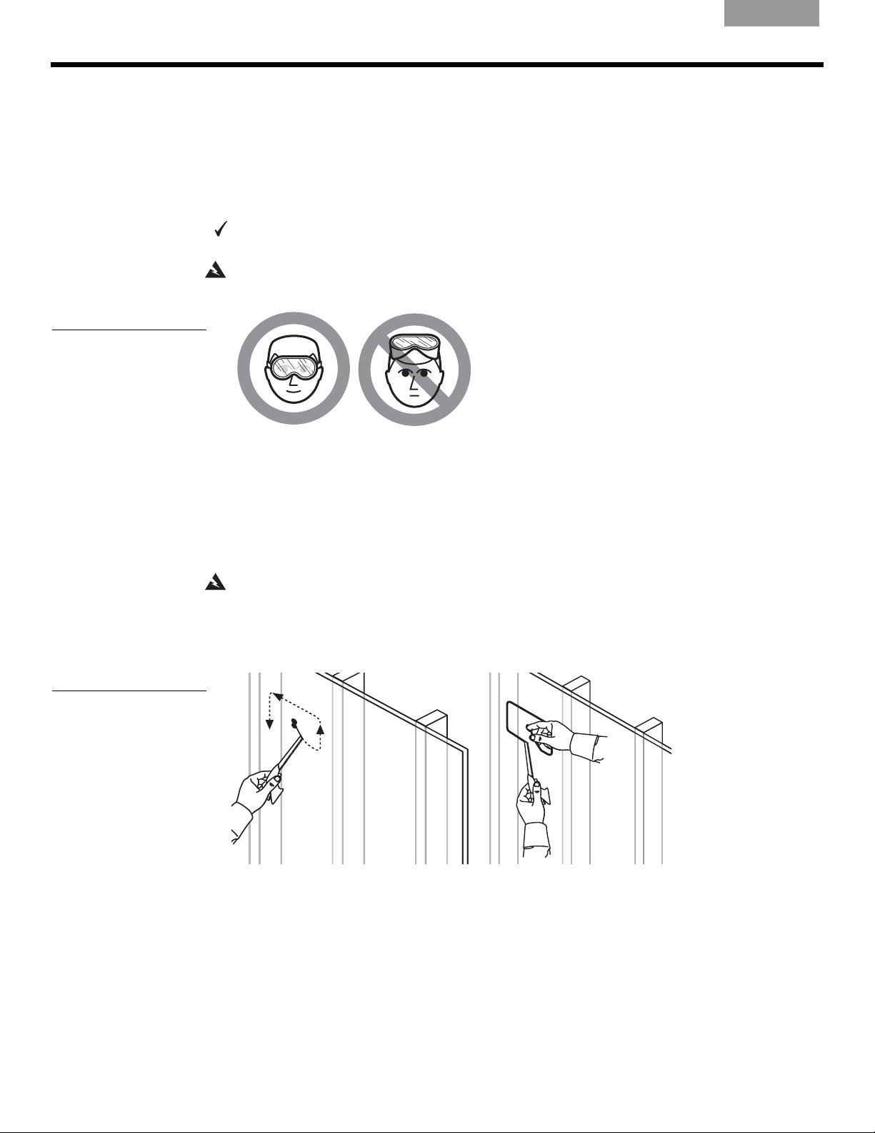
S
TEPS TO INSTALLING
EnglishFrançaisNederlands DeutschItaliano
4. Make a dotted line, using the slotted holes along the bottom of the WHITE CUT-OUT
AREA portion, for the bottom edge of the hole.
5. Remove the template.
7LSIf necessary, use tape to hold the template temporarily in place (see TAPE HERE on the
template). Then run your pencil along the entire template edge, except where there is tape.
Cutting the speaker hole
You need a small saw or specialized cutting tool (for example, a keyhole or drywall saw)
for this step of the installation.
Figure 15
Caution against drilling
without eye protection
Figure 16
Cutting along the outline
(a), and using a finger to
hold the cutout piece (b)
WARNING:
Use eye protection (Figure 15) and be sure to observe all safety precautions while
using the saw or cutting tool.
1. It is best to drill holes inside each corner of the rectangular outline you have drawn,
before you begin cutting. Insert the blade into the pilot hole and cut down and at an angle
until you reach one pencil line.
7LSWhile it is important to cut carefully, remember that the speaker frame overlaps the
wallboard by
1
/4 inch (0.6 cm) when the speaker is in place. Minor cutting inaccuracies will be
hidden behind that frame.
2. Cut around three of four sides of the drawn outline, not all the way around (Figure 16a).
WARNING:
Keep fingers away from the cutting blade.
3. Hook your finger into the pilot hole to keep the wallboard from falling behind the wall, and
then make the final cut (Figure 16b).
4. Using your finger, pull out the piece of wallboard you have just cut.
(a)
(b)
14
Page 15
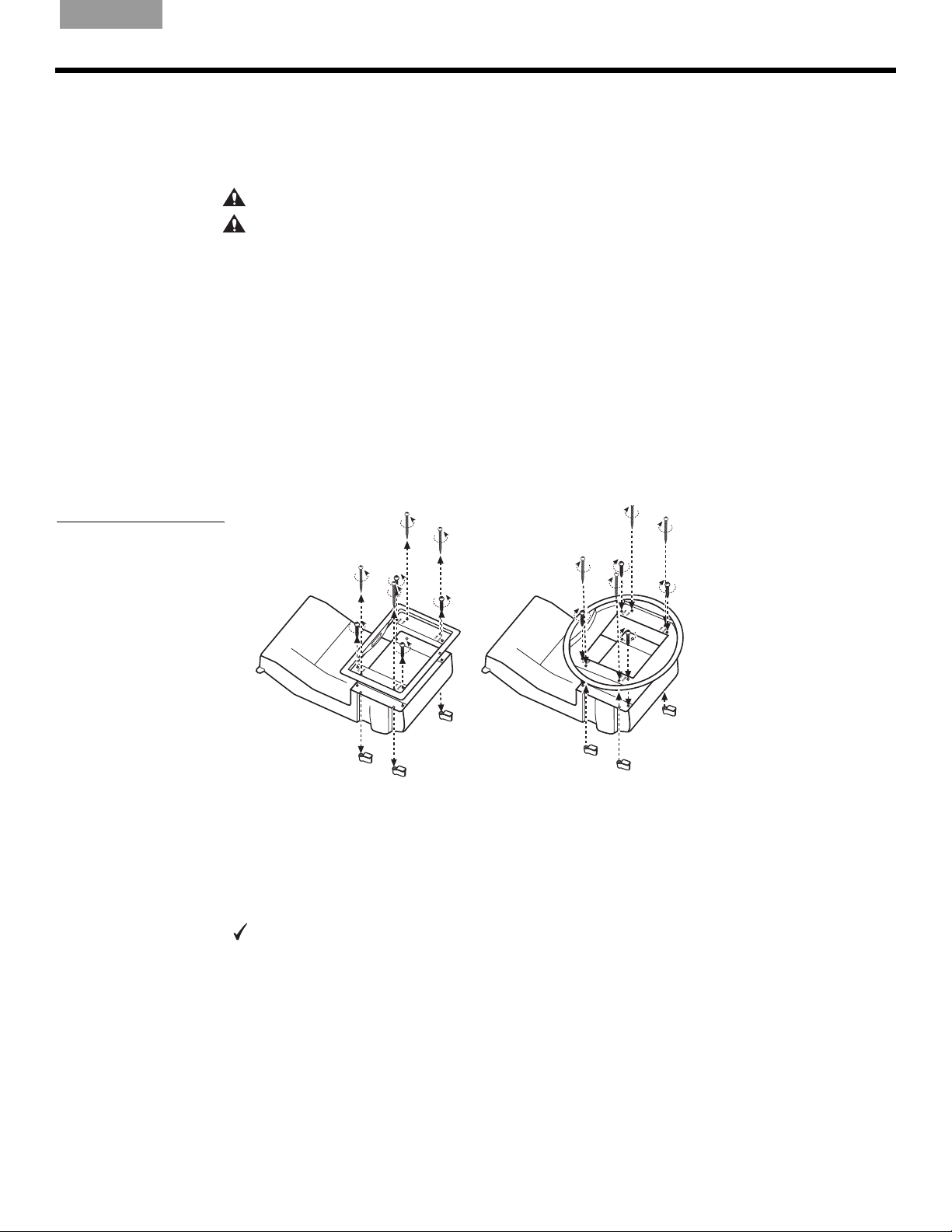
English Français NederlandsDeutsch Italiano
If you encounter insulation behind the wall
You can expect to find insulation in an exterior wall and sometimes in an interior wall. If the
insulation found there is malleable, you can cut and remove some of it from both above and
below the speaker hole to make room for the speaker. Other types of insulation will be difficult
or possibly dangerous to handle.
CAUTION:
CAUTION:
insulation that contains fiberglass.
Beware of hidden nails when reaching into the wall to remove insulation.
Wear gloves and protection for your mouth, nose, and eyes before handling
Reorienting or changing speaker frames
Reorienting the rectangular frame logo
If you intend to mount a rectangular framed speaker upside-down due to a lack of space
below the hole, you will need to reorient the logo before inserting it into the hole.
To do this, remove the frame from the speaker, rotate it 180°, and reattach the frame. There
are four frame screws, labeled GRILLE, that hold the frame in place (See Figure 17 below and
Figure 23 on page 18). Do not confuse them with the dogleg clamp screws that are labeled
WALL.
Do not insert the speaker into the wall without a frame attached. The frame keeps the
speaker from falling into the wall.
S
TEPS TO INSTALLING
Figure 17
Replacing the rectangular
speaker frame with the
round frame
Installing round speaker frames
If you intend to use round speaker frames, install them now by removing the four screws that
hold each rectangular frame and using them to secure the round frames (Figure 17). The logo
is on the round speaker grille, which will be positioned later.
Insert and wire the speaker
You need a Phillips-head screwdriver and optional tape to complete this step.
If your wall is not pre-wired, refer to “What to do when the room is not pre-wired” on page 24.
When wire is within reach of the hole you have cut, follow the procedure below:
1. From inside the newly cut speaker hole, locate and pull out 14 in. (36 cm) or more of the
pre-wired speaker cord (Figure 18 on page 16).
15
Page 16
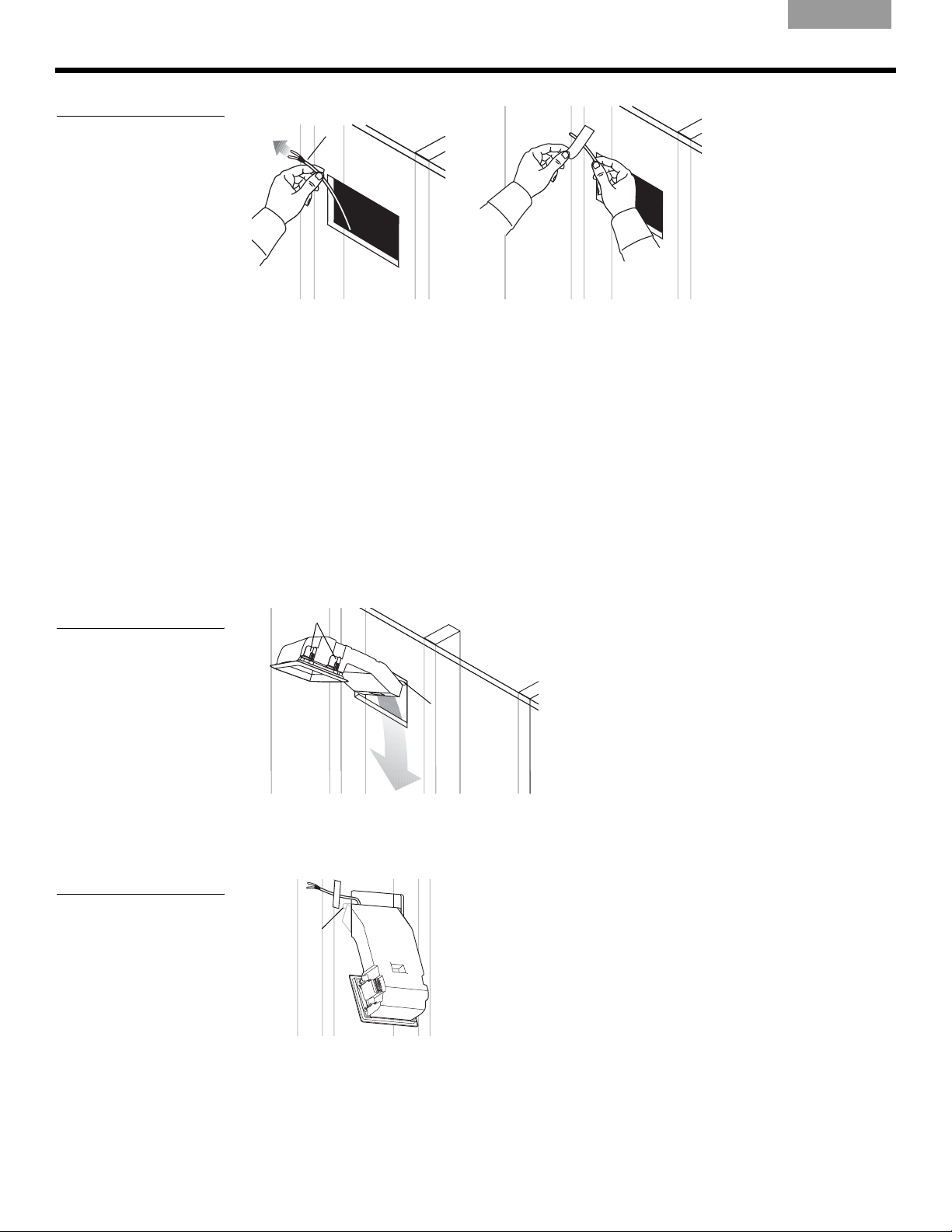
S
TEPS TO INSTALLING
EnglishFrançaisNederlands DeutschItaliano
Figure 18
Pulling the wire up and out,
to the left (a) and securing it
with tape (b).
At least 14 in.
(36 cm) of wire
(a) (b)
2. Use tape to temporarily affix the loose end of the wire above and to the left of the hole
(Figure 18b). This keeps the wire out of the way until you have the speaker partially
inserted in the wall and are ready to make the connections.
Insert the speaker into the opening
Before you follow the steps below, check to be sure none of the dogleg clamps (two on each
side) are protruding from behind the frame of the speaker. If they are, press them back behind
the frame so the speaker will fit into the hole.
7LSLoosen the screw terminals on the upper left side of the speaker before inserting the
speaker into the hole to save effort in making the connections.
1. Use both hands to support the speaker and angle it slightly, so it is diagonal to the hole.
This allows clearance for the wall stops.
2. Insert the bottom of the enclosure through the hole and down part of the way – or up,
depending on your clearance issues (Figure 19).
Figure 19
Partially inserting the
rectangular-faced or roundfaced speaker
Figure 20
Speaker held in place by
wall stops
Dogleg clamps
Wall stop
3. Leave the speaker in this partially inserted position, resting on the wall stops that prevent
it from falling out (Figure 20). This allows ready access to the connection terminals on the
upper left-hand side of the speaker.
Wall stop
16
Page 17
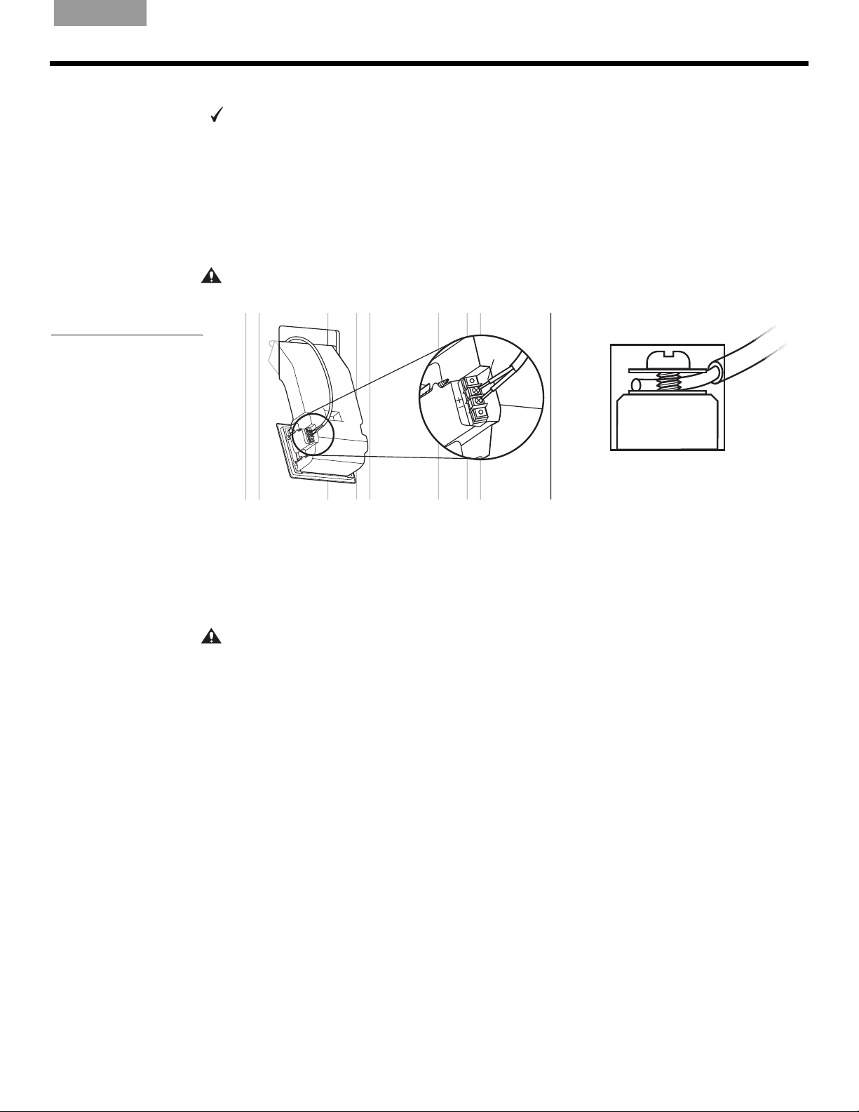
English Français NederlandsDeutsch Italiano
Make the speaker connections
You need a Phillips-head screwdriver for this step.
7LSPay attention to maintaining the proper polarity (+ to + and – to –) with these connections.
An error here will adversely affect speaker performance. Also be sure to tighten each screw
securely, but not enough to cause undesirable compression of the wire.
1. If you have not done so earlier, loosen the screws on both terminals.
2. Insert the end of the marked wire (+) into the positive (+) terminal and tighten the screw
(Figure 21).
3. Insert the end of the unmarked wire (–) into the negative (–) terminal. Tighten the screw.
CAUTION:
components. Trim excess wire and reinsert as necessary.
Figure 21
Attaching wires to the
terminals
Do not allow exposed wires to brush against each other, which could damage your
S
TEPS TO INSTALLING
+
Test the speaker now
With the connections still within reach, now is a good time to test the speaker to make sure it
functions properly before you secure it in the wall.
It may be preferable to begin installing the second speaker now, before you test either one.
When you get the second speaker connected, you can test both speakers, and make sure
they are both functioning fine before proceeding with the installation steps for each one.
CAUTION: If
wire to that first speaker is the only one connected to the receiver/amplifier. This prevents
unattached speaker wires from making contact, which can damage the receiver/amplifier.
To test the speaker:
1. Turn on the receiver/amplifier and play a piece of music that is familiar to you.
2. Listen for clarity and accuracy of the performance from one speaker.
• If you hear a problem, refer to “Troubleshooting” on page 27.
• If the performance sounds fine, test the other speaker, or continue with the installation
steps for this speaker.
you are testing the first speaker before the other one is connected, make sure the
Position the speaker all the way into the hole
1. When the connections are completed, push any excess wire into the hole behind the
speaker (Figure 22 on page 18).
17
Page 18
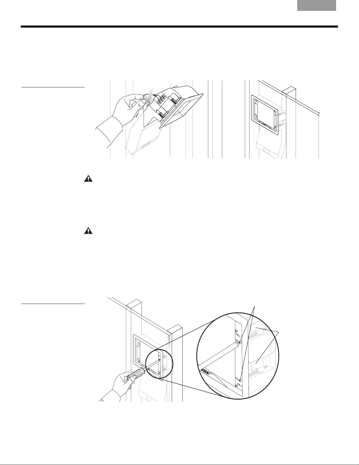
S
TEPS TO INSTALLING
EnglishFrançaisNederlands DeutschItaliano
2. Make sure the frame of the speaker is firmly screwed onto the face. The frame prevents
the speaker from slipping all the way into the hole. Refer to Figure 17 on page 15 if you
need to reverse the frame to orient the Bose logo on the rectangular speaker face.
3. Push the speaker into the hole until the face is straight and flush with the wall
(Figure 22b).
Figure 22
Pushing excess wire behind
the speaker (a) and
Positioning the speaker all
the way in the hole (b)
(a)
Secure the speaker to the wall
CAUTION: If you use a screw gun to tighten any screws, first select the gun’s lowest torque set-
ting (do not exceed 2-4 inch-pounds or 0.2-0.5 N-m of torque). If the screw does not seat properly, finish installing the screw at the next highest torque setting, or by hand.
When the speaker is positioned inside the hole with the face straight and flat against the wall,
you are ready to tighten the dogleg clamp screws, labeled WALL, along the sides of the
frame. The dogleg screws exert pressure from inside to hold the speaker firmly against the
wall. Do not confuse the dogleg screws with those labeled GRILLE, which hold the frame.
CAUTION:
dogleg screws. Too much compression can crush the wallboard, making it crumble. This creates
uneven surface support and can leave gaps between the speaker face and the wall.
Although they should be thoroughly screwed down, be sure not to overtighten the
(b)
Figure 23
Tightening the dogleg
clamp screws
1. Slightly tighten the four dogleg clamp screws (Figure 23) until each one begins to grip.
This is caused by the clamps that swing out and press against the back of the wallboard.
2. With your fingers grasping the frame of the speaker, rock it slightly back and forth into
position. Check for even seating of the face before you tighten the screws any further,
and adjust the speaker if it needs to be straightened.
Dogleg clamp screws
G
R
I
L
L
E
W
A
L
L
W
A
L
L
G
R
I
L
L
E
Dogleg
clamps
3. When the speaker is straight, tighten each screw.
18
Page 19
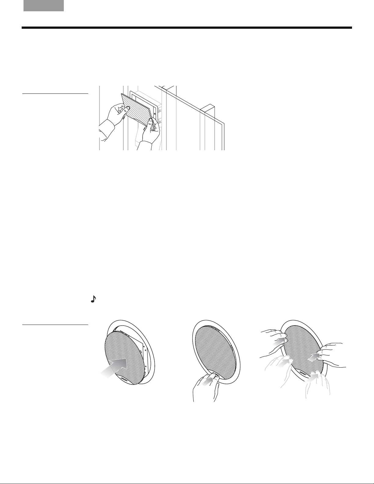
English Français NederlandsDeutsch Italiano
Attaching rectangular grille frames
1. Line up the curved edge of the grille with the curve over the Bose® logo and press that
edge into the speaker frame first (Figure 24).
2. Press the top of the grille firmly into place until you feel some resistance. When the grille
lines up flush with the frame of the speaker, it is seated properly.
Figure 24
Snapping the grille into
place
If the speaker looks crooked
When you step back from the wall, you may notice that the speaker is not straight. If so, it is
easy to adjust the speaker slightly:
1. Remove the grille by inserting a thin-bladed tool between the speaker frame and the grille
and carefully prying it out.
2. Slightly loosen each of the four dogleg clamp screws, labeled WALL.
3. Press on the sides of the speaker frame to shift it up or down into the proper position.
4. Stand back to make sure it is straight. Repeat step 3 if it is not.
5. Tighten all four dogleg clamp screws.
6. Reattach the grille to the front of the speaker.
S
TEPS TO INSTALLING
Figure 25
Attaching round grilles
Attaching round grilles
1. Line up the Bose logo in the desired position.
2. Tuck the Bose logo into the speaker frame first. See Figure 25.
3. Work your way to the top of the grille frame, using both hands to tuck the grille tabs into
the frame. Be careful not to permanently bend the grille tabs.
Note:
insure it is in the desired position before pressing the entire grille into the frame.
When the grille is inserted into the frame, the logo can not be re-positioned. Take care to
19
Page 20

REFERENCE
Painting the speakers
The grille and frame of your Virtually Invisible® 191 speakers can be painted before or after the
speaker is installed. This is optional, however, and Bose cannot be responsible for the quality
of adhesion or finish of non-factory applied paints.
There are different techniques for painting the grille and painting the frame. Be sure to use
paint that is appropriate to the technique you choose.
WARNING:
the proper use of eye protection, ventilation systems, respirators or filter masks, and fire safety
equipment if flammable solvents are used.
Painting the grille
It is important to prevent paint from clogging the grille perforations, which can adversely
affect performance. You can use a dry brush technique or spray paint the grille. However, do
not use a paint roller:
• Remove the grille from the speaker if it has been installed.
• Before you begin to paint, clean the grille to remove possible contaminants. Even
fingerprints can prevent uniform coverage.
• Check to be sure the paint is distributed evenly and covers the grille thoroughly. If not, you
may need to paint the inside of the grille to fix the problem.
EnglishFrançaisNederlands DeutschItaliano
Follow all recommended safety procedures for the chemicals involved. This includes
• When it is dry, protect the painted grille with a clean cloth or tissue paper until you attach it
to the speaker.
Using a dry brush technique
Unthinned latex paint is appropriate for this method. Be sure to put down enough paper to
cover your work area and allow for repeatedly blotting the brush.
1. Dip the tip of a clean, dry brush in the paint.
2. Stroke across the paper to reduce the amount of paint on the brush. When you can see
individual bristle marks, the brush is ready to use on the grille.
3. Stroke lightly back and forth on the front of the grille, in a horizontal direction, until you
need more paint.
7LSIf paint clogs any of the grille perforations, try angling your stroke to unclog it, or blow
gently on the clog.
4. Repeat the above steps until the outside of the grille is completely covered.
5. Turn the grille 180° and repaint the entire surface using back-and-forth strokes again.
Using a spray technique
Latex or oil-based architectural paint requires thinning for use with a siphon-feed spray gun
set for 30 psi (2.1 bar) and for application in a 3- to 5-inch (7.6-12.7 cm) fan pattern. The
thinning formula depends on the type of paint you are using.
• Thin vinyl acrylic latex paint as follows:
To 6 parts of paint, add 3 parts of water and mix thoroughly. Add 1 part of denatured ethyl
alcohol (which breaks down paint particles so they do not clog the grille) and mix again.
• For use of architectural or automotive paints:
This type of paint should be used by a professional with the right equipment and technique.
This paint must also be thinned, using a solvent.
• Lacquer or enamel spray paint comes in an aerosol can and needs no further thinning.
20
Page 21
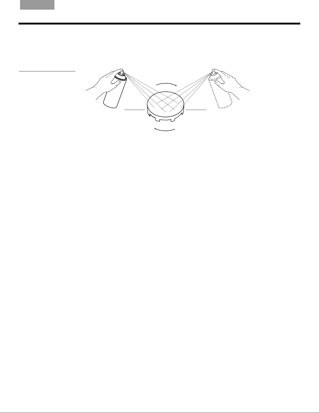
English Français NederlandsDeutsch Italiano
1. To prevent dirt or dried paint particles from blowing back into the grille perforations,
suspend the grille or place it on a wire screen.
2. Apply the paint to the grille surface at a 45° angle. Then rotate the grille by 180° and
repaint it at 45°.
Figure 26
Angling and turning used to
apply the paint twice
45°
7LSPiercing a perforation with a sharp implement to remove a clog can cosmetically
damage the grille and is not recommended. If paint clogs any of the grille perforations, blow
gently in that area to unclog it. If that does not work, immediately wash the grille with the
appropriate solvent. Make sure the grille is thoroughly dry before repainting.
180°
45°
R
EFERENCE
The paint may feel dry in a few minutes. However, if alcohol has been added, it may take
several days to fully cure.
Painting the frame
Before you begin, protect the speaker cones by inserting the paint shield that came in the
carton. Then you can use the same conventional spray or roller equipment used to paint the
wall or ceiling.
You can use either latex or oil-based paints, which adhere to the speaker frame. However,
both can be easily scratched through careless handling.
Be careful so the paint does not puddle or run. You may want to use a brush for spreading
paint where needed.
Help for the beginning installer
This section provides information that may be helpful for the do-it-yourself installer.
Optional items that will assist you:
• Clothing appropriate for the job
• Gloves and protection for your mouth, nose, and eyes
• A drop cloth or other material to protect the area from debris
• A wire snake for running speaker cord behind wallboard
• A sturdy stool or ladder for installing speakers above your head
21
Page 22

R
EFERENCE
EnglishFrançaisNederlands DeutschItaliano
Accessories that can help
For installation in a drop ceiling (where tile is installed below the ceiling joists), Bose offers an
optional Drop Ceiling Kit for two speakers. It protects the tile from bearing the weight of the
speakers. Instructions are included with the kit.
For installation in new construction, Bose offers a Rough-in Kit for two speakers. It is
designed for use after the studs are in place and before the wallboard is added to reserve a
place for the speakers and indicate where the wallboard hole should be made. It also
protects the wallboard by providing additional support for the dogleg clamps that secure the
speaker to the wall. Instructions are included with the kit.
For more information or to order an accessory, contact your Bose dealer. Or, to contact Bose
directly, refer to the address list included in the carton.
Using speaker cord
Before you cut any cord, estimate how much will be needed by measuring the distance from
the receiver/amplifier to where each speaker will be installed. Make some allowance if the
cord must go around corners or through walls, and leave at least 14 in. (36 cm) of cord to pull
from the wall for making the connections easily. Allow extra length if you are installing ceiling
speakers, so that you can make connections while standing on the floor.
Wire recommendations
.
Gauge Maximum Length
18 AWG (0.82 mm2)
16 AWG (1.3 mm2)
14 AWG (2.1 mm2) 50 ft (15 m)
20 ft (6 m)
30 ft (9 m)
Preparing the speaker cord
Speaker cord consists of two insulated wires. The insulation around one wire is marked
(striped, collared, or ribbed) to identify it as positive. The other wire is negative.
Note:
1. Strip approximately
It is sometimes difficult to distinguish wire markings. Inspect both wires carefully.
1
e2inch (13 mm) of insulation from both wires. You will need a wire
cutter and wire stripper for this work.
2. Twist the bare end of each wire so loose strands will not touch across terminals.
Be sure to connect each wire to the proper terminal, positive to positive (+) and negative to
negative (–).
Before the wallboard goes up
There are some standard guidelines for working in unfinished construction.
• Begin this work after the studs and joists are in and the electrical wiring is completed.
• Snap a chalk line across the face of the studs or the bottom of the joists and move
backward as you drill, so you can keep the last hole drilled in your line of sight.
22
Page 23
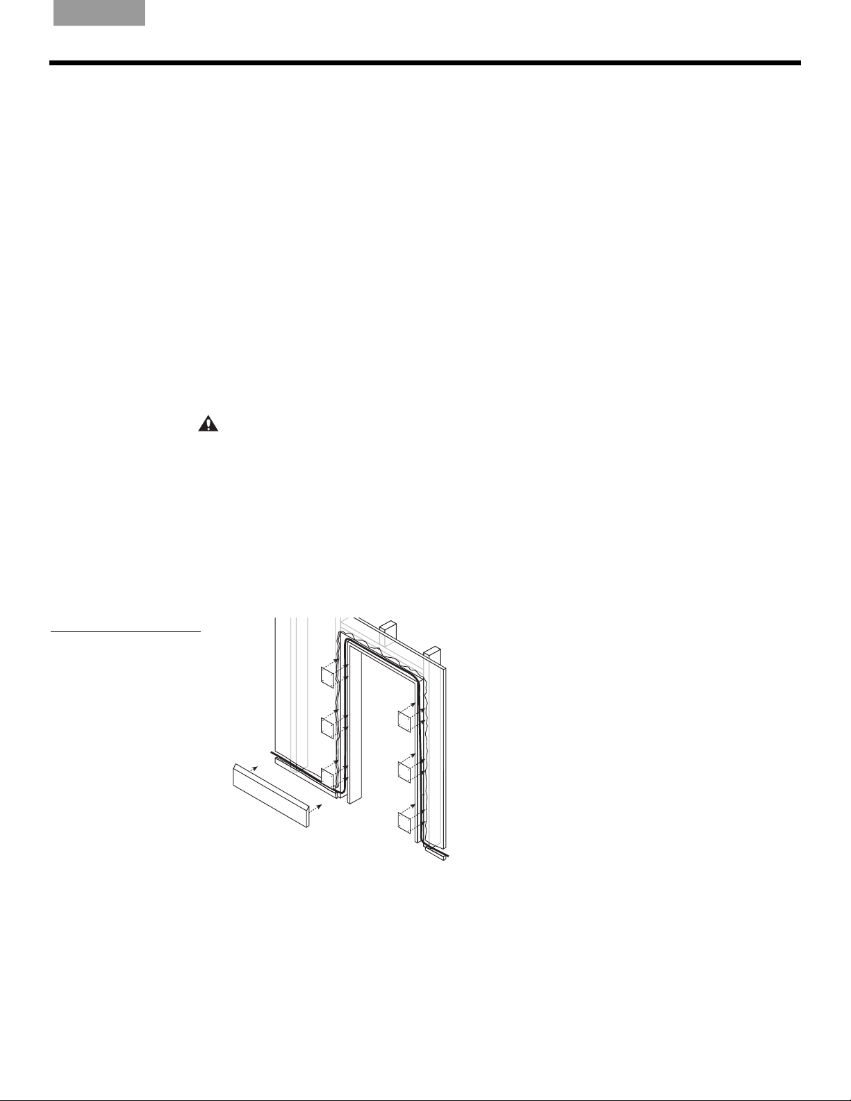
English Français NederlandsDeutsch Italiano
• Never run speaker cord and electrical cable through the same hole or into the same
junction box.
• If a short section of the cord must run parallel to nearby electrical cable, keeping that run to
the absolute minimum will result in less interference.
• Use metal conduit or shielded speaker cord if the cord must run next to electrical cable for
10 ft. (3 m) or more.
• Use cable clamps or large wire staples to fasten the cord to a joist or stud wherever the
cord runs more than 4
1
/2 ft. (1.4 m) from a hole.
• Use protective guard strips, raceways, or conduits to protect the cord from being stepped
on or compressed in an attic or crawl space.
Installing in a pre-wired room
An installation is simplest when the room has been pre-wired during construction. In that
case, the builder will have left speaker cord within easy reach of the intended speaker
positions. In the ideal situation, after cutting the speaker hole you can simply reach inside to
locate the length of cord the builder has installed.
If you are not sure that you have a pre-wired room, or do not know where the wiring is
located, check the architectural drawings of your room or call the builder.
R
EFERENCE
Figure 27
Running cord behind
baseboards and a
doorjamb
CAUTION:
It is important to know where the pre-wired cord is to prevent damaging it while
drilling or cutting into the wall.
Where the walls are finished
Here are some suggestions for how to make this job easier.
Look for ways to conceal cord outside the walls (See Figure 27):
• Along or behind baseboards
• Under carpets (using special flat speaker cord for under-the-rug speaker runs)
• Under doorjambs.
23
Page 24
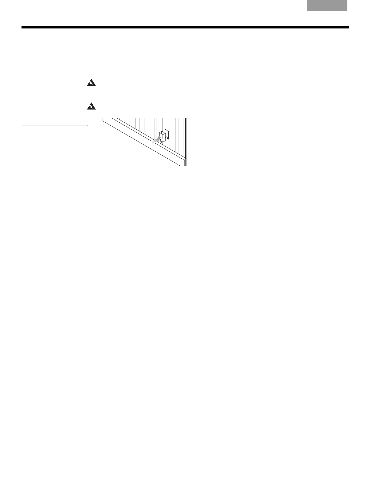
R
EFERENCE
Figure 28
An open-backed junction
box that allows cord to
come through the wall near
the receiver or amplifier
EnglishFrançaisNederlands DeutschItaliano
What to do when the room is not pre-wired
In this case, you will need to run speaker cord from the receiver or amplifier through the wall
to the area you have chosen for installing the speakers. You will need to mount an
open-backed junction box in the wall near the receiver or amplifier (Figure 28).
You also need to observe safe and practical standards:
WARNING:
have hazards, such as electrical wiring, conduits, or plumbing concealed behind them. Follow all
other safety precautions.
WARNING:
• Use a drill bit large enough for the cord you will pull through the holes.
• Use an auger bit, if possible, to make the work of drilling multiple holes less tiring.
Make sure the spot chosen is safe for drilling. Do not drill through surfaces that may
Consult local building codes to inform yourself of the requirements in your area.
• Do not drill through a load-bearing beam. Consult the building contractor if this is an issue.
• Keep cord 3 to 4 ft. (1 to 1.3 m) away from electrical cord, which can create a hum or buzz
in the speakers. See Figure 29 on page 25.
• To avoid nails, drill holes in the center of each stud or joist.
• Use a nail plate to protect the cord if your only option is to notch a stud or joist.
• Line up holes as perfectly as possible to make pulling the cord through easier.
• Pull the cord so there are no sags but do not pull tight enough to create tension.
Find the easiest path for cord that must run behind the wallboard:
• Choose interior walls, which are less likely to have insulation packed behind the wallboard.
• Use an attic or basement run where possible, so you have easy access and can see where
plumbing, electrical wires, and other impediments occur.
• In slab construction, consider using plenum-rated wire run through heating or air
conditioning vents.
24
Page 25
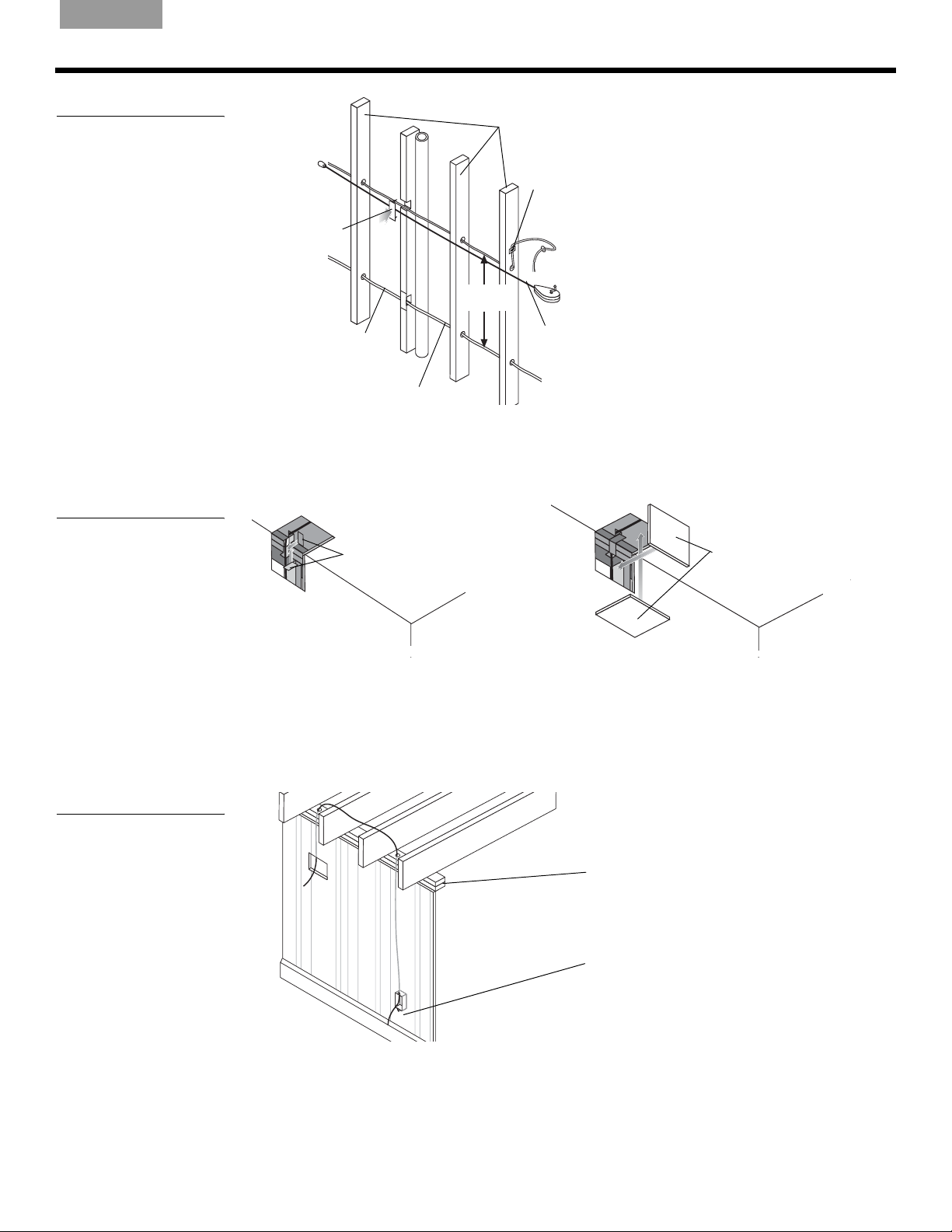
English Français NederlandsDeutsch Italiano
R
EFERENCE
Figure 29
Techniques to use for
running speaker cord
through studs or joists
Figure 30
Running cord around a
corner with nail plates for
protection (a) and cutout
pieces as patches
Studs
Wire Staple
Nail plate
3-4’
(1-1.3m)
Speaker cord
Electrical wire
Plumb line
for chalk mark
If you must route cord around a corner, you will need to cut out a rectangular piece of
wallboard on either side of the joist at that corner. Use each regular-shaped cutout as the
patch for the wall when you finish. By reaching through the cutout, you can notch the joist to
make room for the cord and use nail plates to cover the cord in each notch (Figure 30).
(a)
Nail plates
Ceiling
Electrical wire
(b)
Cutout pieces
Ceiling
Figure 31
Running the cord up
through the attic
Wall
Wall
Wall
Wall
To patch the wall, reposition the cutout pieces and use joint tape and joint compound to hold
them in place. When they are dry, sand and paint the area to match surrounding surfaces.
It is common to run cord from a speaker location in a wall or ceiling to the attic and through
the wooden top plate that runs horizontally across the top of the vertical studs. You can then
run the cord to the spot above the junction box near the receiver or amplifier. Drill through the
top plate at that point and route the cord through the hole and down into the wall (Figure 31).
Top plate
Open-backed
junction box
25
Page 26

R
EFERENCE
EnglishFrançaisNederlands DeutschItaliano
Installing in an exterior wall
If you choose to install these speakers in an exterior wall (abutting the outside of your house),
you may encounter insulation behind the wallboard. This can complicate the installation,
requiring you to trim and push malleable insulation out of the way. You will need to wear eye
protection and gloves for working with fiberglass insulation.
WARNING:
into the wall. Choose a different location for the speakers instead.
Insulation will also impede your use of a pilot hole to test the size of the space behind the
wallboard. Doing such a test is recommended to make sure the space is large enough before
cutting a speaker-sized hole.
If you believe the insulation inside a wall may be composed of asbestos, do not cut
Use special care in cutting through plaster and lath
For wall construction of plaster and lath, use special care to prevent plaster from cracking:
• After you have drawn an outline of the hole to cut, tape around the outline and use a sharp
blade to make shallow cuts where the hole will be.
• Then, within the outline only, chip the plaster away until you expose the lath underneath.
Finally, cut through the lath very carefully. Using an electric sabre saw can be quick but risky.
We recommend using a hand saw and proceeding cautiously to avoid damaging the
surrounding plaster.
Special considerations in cold climate regions
With exterior wall installations in regions where outdoor temperatures dip below freezing for
days at a time, using a humidifier can cause condensation to form inside the speakers. This
can be more of a problem if the speakers are mounted upside down.
If you must mount in an exterior wall:
• Avoid installing the speakers upside down.
• Leave some of the insulation between the speakers and the exterior wall.
• Refrain from setting the humidifier on high, especially when outside temperatures are below
freezing.
26
Page 27

English Français NederlandsDeutsch Italiano
Troubleshooting
R
EFERENCE
Neither speaker
plays
The bass or treble
is weak
Only one speaker
plays
Only one speaker
still plays
• Check the settings on your receiver/amplifier. Refer to the owner’s guide that came with it for
instruction on settings.
• If your Virtually Invisible
®
191 speakers are the second pair of speakers connected to your
receiver/amplifier, make sure the connections have been made to the “B” terminals and that
the “B” speakers are selected to play.
• Check the tonal balance setting on your receiver/amplifier.
• Check for consistent polarity of the connections (+ to + and – to –) to the receiver/amplifier and
to the speaker. Review “Make the speaker connections” on page 17.
• Check the balance control on your receiver/amplifier and make sure it is centered.
• Check the wires connected to the speaker that does not play. Make sure the wires are in good
condition and are firmly connected. Review “Make the speaker connections” on page 17.
• Trace the cord from the speaker in question to the receiver/amplifier. Disconnect the cord from
the receiver/amplifier channel and reconnect it to a different receiver/amplifier channel.
– If the performance is now fine, the problem lies in the original receiver/amplifier channel,
the component source of the music, or the connections between the receiver/amplifier
and the source. Check all of those to make sure they are performing properly. Reconnect
the speaker to the correct channel of a functioning receiver/amplifier.
– If the problem persists, its source is either the speaker wire or the speaker in question.
Follow the next instruction.
• Disconnect the cord from the speaker in question and reconnect it to the second speaker.
– If the performance is now fine, the problem lies in the original speaker. Contact your
authorized Bose
®
dealer, who will arrange for service. Or, to contact Bose directly, refer to
the address list included in the carton.
• Before you take steps to replace and re-run the speaker wire, recheck all of the connections.
Static or noise from
• Check the connections at the speaker and at the receiver/amplifier. Make sure the wires are in
one speaker
Customer service
Warranty period
– If the problem persists, its source is the speaker wires. Follow the next instruction.
Then repeat the procedure for pinning down the problem source, above.
good condition, are firmly connected, and no wires are touching across terminals. Also check
the connections from the receiver/amplifier to the component source of the music.
– If the problem persists, follow the troubleshooting instructions for “Only one speaker still
plays,” above.
For additional help in solving problems, contact your Bose dealer. Or, to contact
®
Bose
Customer Service, refer to the address list included in the carton.
Bose Virtually Invisible® 191 speakers are covered by a limited 5-year transferable warranty.
Details of coverage are on the warranty card that came with your speakers. Please fill out the
information section, detach, and mail it to Bose.
27
Page 28

R
EFERENCE
Accessories
• Drop Ceiling Kit for two speakers
Protects the tile from bearing the weight of the speakers. Instructions included.
• Rough-in Kit for two speakers
Reserves a place for the speakers after the studs are in place and before the wallboard is
added, and indicates where the wallboard hole should be made. Instructions included.
For further information or to order accessories, contact your Bose dealer. Or, to call Bose
directly, refer to the address list included in the carton.
Technical information
EnglishFrançaisNederlands DeutschItaliano
Features
• Virtually Invisible
®
and Articulated Array® speaker design
• Proprietary enclosure technology
• Stereo Everywhere
®
speaker performance
• Paintable grille
• Syncom
®
computer tested
Compatibility
• Compatible with amplifiers or receivers rated 10-100W per channel/rated 4 to 8 ohms
• 50W IEC continuous power handling; rated 6 ohms
Driver complement
• Two (2) 2
1
/2" (6.4 cm) full-range drivers per speaker
Enclosure
• Ported and molded high-impact polystyrene
• White frame and grille
Dimensions
• Each speaker:
3
13
/4"H x 77/8"W x 37/8"D (34.9 cm H x 19.9 cm W x 9.8 cm D)
• Wall or ceiling surface area required for each:
Rectangular-faced speaker – 8
Round-faced speaker – 11
3
/4"W x 6"H (20.5 cm x 14 cm)
1
/4" diameter (26 cm)
28
Weight
• 4.5 lb. (2.0 kg) each
Page 29

English Français NederlandsDeutsch Italiano
29
Page 30

SICHERHEITSHINWEISE
Wichtige Sicherheitshinweise
Lesen Sie diese Anleitung vollständig durch, bevor Sie mit den Arbeiten beginnen. Schätzen Sie Ihre Erfahrung im
Umgang mit den Werkzeugen richtig ein, und beachten Sie die hier erwähnten Vorsichtsmaßnahmen. Wenn Sie
sich nicht sicher sind, ob Sie die Installation durchführen können, wenden Sie sich an den Händler, bei dem Sie
das Produkt gekauft haben, an einen Elektrotechniker oder an einen qualifizierten Fachbetrieb für Audio/VideoInstallationen. Beschreiben Sie die durchzuführenden Arbeiten, und holen Sie einen Kostenvoranschlag ein, bevor
Sie entsprechende Dienstleistungen in Auftrag geben.
WARNUNG: Die Installation muss in Übereinstimmung mit den jeweils gültigen Regelungen des National Electrical
Code, ANSI/NFPA 70, und/oder des National Fire Alarm Code, ANSI/NFPA 72, ausgeführt werden. Die Verkabelungsart
und räumliche Abtrennung muss so erfolgen, dass der Betrieb des Lautsprechers nicht gestört wird.
ACHTUNG: Informieren Sie sich über die örtlichen Bauvorschriften, bevor Sie mit der Installation beginnen.
ACHTUNG: Dieses Produkt ist nicht für die Verwendung in Luftkammern gedacht.
ACHTUNG: Wenn die Anweisungen in dieser Anleitung nicht befolgt werden, kann die Garantie der Lautsprecher
verfallen.
Die Anweisungen beziehen sich ausschließlich auf Fachwerks- oder ähnliche
Konstruktionen.
Jeder Lautsprecher benötigt 20,5 cm horizontalen sowie 35,6 cm vertikalen Freiraum hinter der Wand oder Decke;
von der Oberfläche der Wand (max. 1,9 cm dick) muss ein Freiraum von 10,5 cm Tiefe gewährleistet sein.
EnglishFrançaisNederlands DeutschItaliano
Bose empfiehlt, die Lautsprecher nur in Fachwerks- oder ähnlichen Konstruktionen zu installieren, bei denen
genügend Freiraum zwischen den Balken vorhanden ist (z. B. in Wand- oder Deckenkonstruktion mit BalkenNormmaßen 38 x 89 mm oder 38 x 140 mm). Die Anweisungen in dieser Anleitung beziehen sich ausschließlich auf
diese Art der Installation.
Hinweis: Die Lautsprecher sind nicht für die Installation in Mauerwerk oder gemauerten Decken vorgesehen.
Wichtige Sicherheitshinweise
1. Lesen Sie diese Anweisungen – für alle Komponenten und vor dem Gebrauch dieses Produkts.
2. Bewahren Sie diese Anweisungen auf – zum späteren Nachschlagen.
3. Beachten Sie alle Warnhinweise – am Produkt und in dieser Bedienungsanleitung.
4. Befolgen Sie alle Anweisungen.
5. Blockieren Sie keine Lüftungsöffnungen, und nehmen Sie die Installation nur nach den Anweisungen
des Herstellers vor.
6. Verwenden Sie nur Zubehör-/Anbauteile, die vom Hersteller zugelassen sind.
Bose® Virtually Invisible® 191 Lautsprecher erfüllt die folgenden Spezifikationen:
Dieses Produkt entspricht den Bestimmungen der EMV-Richtlinie 89/336/EWG und der Niederspannungs-Richtlinie
73/23/EWG. Die vollständige Konformitätserklärung ist einsehbar unter <www.bose.com>.
Für Ihre Unterlagen
Die Seriennummern befinden sich mittig auf der Rückseite an jedem Virtually Invisible®191 Lautsprecher.
Seriennummern:______________________________ und ____________________________________________
Name des Fachhändlers:_______________________________________________________________________
Telefonnummer:_____________________________________Kaufdatum: _______________________________
Wir empfehlen Ihnen, die Kaufquittung und Garantiekarte zusammen mit dieser Bedienungsanleitung
aufzubewahren.
2
Page 31

English Français NederlandsDeutsch Italiano
INHALT
EINFÜHRUNG 4
Vor dem Start . . . . . . . . . . . . . . . . . . . . . . . . . . . . . . . . . . . . . . . . . . . . . . . . . . . . . . . . . . . . . . . . . . . . . . . . . . . . . . . . 4
Verbesserung durch Veränderung . . . . . . . . . . . . . . . . . . . . . . . . . . . . . . . . . . . . . . . . . . . . . . . . . . . . . . . . . . . . . . . . 4
VORBEREITUNG 5
Auspacken . . . . . . . . . . . . . . . . . . . . . . . . . . . . . . . . . . . . . . . . . . . . . . . . . . . . . . . . . . . . . . . . . . . . . . . . . . . . . . . . . . 5
Weitere benötigte Materialien . . . . . . . . . . . . . . . . . . . . . . . . . . . . . . . . . . . . . . . . . . . . . . . . . . . . . . . . . . . . . . . 5
Lautsprecher positionieren . . . . . . . . . . . . . . . . . . . . . . . . . . . . . . . . . . . . . . . . . . . . . . . . . . . . . . . . . . . . . . . . . . . . . 6
Drei Tipps zur Lautsprecherpositionierung . . . . . . . . . . . . . . . . . . . . . . . . . . . . . . . . . . . . . . . . . . . . . . . . . . . . 6
Bevorzugte Lautsprecherform auswählen . . . . . . . . . . . . . . . . . . . . . . . . . . . . . . . . . . . . . . . . . . . . . . . . . . . . . 7
Wandtyp ermitteln und Vorgehensweise festlegen . . . . . . . . . . . . . . . . . . . . . . . . . . . . . . . . . . . . . . . . . . . . . . 7
Platzierung in Wänden . . . . . . . . . . . . . . . . . . . . . . . . . . . . . . . . . . . . . . . . . . . . . . . . . . . . . . . . . . . . . . . . . . . . 7
Platzierung in Decken . . . . . . . . . . . . . . . . . . . . . . . . . . . . . . . . . . . . . . . . . . . . . . . . . . . . . . . . . . . . . . . . . . . . . 8
INSTALLATION 9
Vor dem Bohren . . . . . . . . . . . . . . . . . . . . . . . . . . . . . . . . . . . . . . . . . . . . . . . . . . . . . . . . . . . . . . . . . . . . . . . . . . . . . . 9
Probebohrung zum Ermitteln des Freiraums . . . . . . . . . . . . . . . . . . . . . . . . . . . . . . . . . . . . . . . . . . . . . . . . . . . . . . . . 9
Schablone verwenden . . . . . . . . . . . . . . . . . . . . . . . . . . . . . . . . . . . . . . . . . . . . . . . . . . . . . . . . . . . . . . . . . . . . 9
Probebohrung setzen . . . . . . . . . . . . . . . . . . . . . . . . . . . . . . . . . . . . . . . . . . . . . . . . . . . . . . . . . . . . . . . . . . . . . 10
Raum hinter der Bohrung prüfen . . . . . . . . . . . . . . . . . . . . . . . . . . . . . . . . . . . . . . . . . . . . . . . . . . . . . . . . . . . . 11
Nach erfolgreicher Probebohrung . . . . . . . . . . . . . . . . . . . . . . . . . . . . . . . . . . . . . . . . . . . . . . . . . . . . . . . . . . . 13
Probebohrung verschließen . . . . . . . . . . . . . . . . . . . . . . . . . . . . . . . . . . . . . . . . . . . . . . . . . . . . . . . . . . . . . . . . 13
Wand für den Einbau der Lautsprecher vorbereiten . . . . . . . . . . . . . . . . . . . . . . . . . . . . . . . . . . . . . . . . . . . . . . . . . . 13
Öffnung ausmessen und markieren . . . . . . . . . . . . . . . . . . . . . . . . . . . . . . . . . . . . . . . . . . . . . . . . . . . . . . . . . . 13
Lautsprecheröffnung aussägen . . . . . . . . . . . . . . . . . . . . . . . . . . . . . . . . . . . . . . . . . . . . . . . . . . . . . . . . . . . . . 14
Neuausrichten oder Ändern der Lautsprecherrahmen . . . . . . . . . . . . . . . . . . . . . . . . . . . . . . . . . . . . . . . . . . . . . . . . . 15
Logo des rechteckigen Rahmens neu ausrichten . . . . . . . . . . . . . . . . . . . . . . . . . . . . . . . . . . . . . . . . . . . . . . . 15
Runde Lautsprecherrahmen installieren . . . . . . . . . . . . . . . . . . . . . . . . . . . . . . . . . . . . . . . . . . . . . . . . . . . . . . . 15
Lautsprecher einhängen und anschließen . . . . . . . . . . . . . . . . . . . . . . . . . . . . . . . . . . . . . . . . . . . . . . . . . . . . . . . . . . 15
Lautsprecher in die Öffnung einhängen . . . . . . . . . . . . . . . . . . . . . . . . . . . . . . . . . . . . . . . . . . . . . . . . . . . . . . . 16
Lautsprecher anschließen . . . . . . . . . . . . . . . . . . . . . . . . . . . . . . . . . . . . . . . . . . . . . . . . . . . . . . . . . . . . . . . . . 17
Lautsprecher prüfen . . . . . . . . . . . . . . . . . . . . . . . . . . . . . . . . . . . . . . . . . . . . . . . . . . . . . . . . . . . . . . . . . . . . . . 17
Lautsprecher ganz in die Öffnung einsetzen . . . . . . . . . . . . . . . . . . . . . . . . . . . . . . . . . . . . . . . . . . . . . . . . . . . 17
Lautsprecher in der Wand sichern . . . . . . . . . . . . . . . . . . . . . . . . . . . . . . . . . . . . . . . . . . . . . . . . . . . . . . . . . . . . . . . . 18
Rechteckige Gitter befestigen . . . . . . . . . . . . . . . . . . . . . . . . . . . . . . . . . . . . . . . . . . . . . . . . . . . . . . . . . . . . . . 19
Runde Gitter befestigen . . . . . . . . . . . . . . . . . . . . . . . . . . . . . . . . . . . . . . . . . . . . . . . . . . . . . . . . . . . . . . . . . . . 19
REFERENZ 20
Anstreichen der Lautsprecher . . . . . . . . . . . . . . . . . . . . . . . . . . . . . . . . . . . . . . . . . . . . . . . . . . . . . . . . . . . . . . . . . . . 20
Gitter anstreichen . . . . . . . . . . . . . . . . . . . . . . . . . . . . . . . . . . . . . . . . . . . . . . . . . . . . . . . . . . . . . . . . . . . . . . . . 20
Rahmen anstreichen . . . . . . . . . . . . . . . . . . . . . . . . . . . . . . . . . . . . . . . . . . . . . . . . . . . . . . . . . . . . . . . . . . . . . . 21
Hilfe für die Installation . . . . . . . . . . . . . . . . . . . . . . . . . . . . . . . . . . . . . . . . . . . . . . . . . . . . . . . . . . . . . . . . . . . . . . . . . 21
Zusätzliche Gegenstände, die Sie brauchen könnten: . . . . . . . . . . . . . . . . . . . . . . . . . . . . . . . . . . . . . . . . . . . . 21
Hilfreiches Zubehör . . . . . . . . . . . . . . . . . . . . . . . . . . . . . . . . . . . . . . . . . . . . . . . . . . . . . . . . . . . . . . . . . . . . . . 22
Lautsprecherkabel . . . . . . . . . . . . . . . . . . . . . . . . . . . . . . . . . . . . . . . . . . . . . . . . . . . . . . . . . . . . . . . . . . . . . . . 22
Vorbereiten des Lautsprecherkabels . . . . . . . . . . . . . . . . . . . . . . . . . . . . . . . . . . . . . . . . . . . . . . . . . . . . . . . . . 22
Vor der Montage der Gipskartonplatten . . . . . . . . . . . . . . . . . . . . . . . . . . . . . . . . . . . . . . . . . . . . . . . . . . . . . . . 22
Installation in vorverkabeltem Raum . . . . . . . . . . . . . . . . . . . . . . . . . . . . . . . . . . . . . . . . . . . . . . . . . . . . . . . . . 23
Bei bereits bestehenden Wänden . . . . . . . . . . . . . . . . . . . . . . . . . . . . . . . . . . . . . . . . . . . . . . . . . . . . . . . . . . . 23
Vorgehen bei nicht vorverkabelten Räumen . . . . . . . . . . . . . . . . . . . . . . . . . . . . . . . . . . . . . . . . . . . . . . . . . . . 24
Installation in Außenwänden . . . . . . . . . . . . . . . . . . . . . . . . . . . . . . . . . . . . . . . . . . . . . . . . . . . . . . . . . . . . . . . 26
Vorsicht beim Sägen in Ständerwerk/Putz . . . . . . . . . . . . . . . . . . . . . . . . . . . . . . . . . . . . . . . . . . . . . . . . . . . . . 26
Besondere Hinweise für Gegenden mit niedrigen Außentemperaturen . . . . . . . . . . . . . . . . . . . . . . . . . . . . . . . 26
Fehlersuche . . . . . . . . . . . . . . . . . . . . . . . . . . . . . . . . . . . . . . . . . . . . . . . . . . . . . . . . . . . . . . . . . . . . . . . . . . . . . . . . . 27
Kundendienst . . . . . . . . . . . . . . . . . . . . . . . . . . . . . . . . . . . . . . . . . . . . . . . . . . . . . . . . . . . . . . . . . . . . . . . . . . . . . . . . 28
Garantie . . . . . . . . . . . . . . . . . . . . . . . . . . . . . . . . . . . . . . . . . . . . . . . . . . . . . . . . . . . . . . . . . . . . . . . . . . . . . . . . . . . . 28
Zubehör . . . . . . . . . . . . . . . . . . . . . . . . . . . . . . . . . . . . . . . . . . . . . . . . . . . . . . . . . . . . . . . . . . . . . . . . . . . . . . . . . . . . 28
Technische Daten . . . . . . . . . . . . . . . . . . . . . . . . . . . . . . . . . . . . . . . . . . . . . . . . . . . . . . . . . . . . . . . . . . . . . . . . . . . . 28
3
Page 32

EINFÜHRUNG
Vor dem Start
ACHTUNG: Lesen Sie diese Anleitung aufmerksam durch, bevor Sie Sägearbeiten ausführen.
Bei dieser Art der Installation sind viele Faktoren zu berücksichtigen.
Vielen Dank, dass Sie sich für die Installation der Bose
in Ihren Räumen entschieden haben. Dank innovativer Technik und fortschrittlicher
Gestaltung bieten diese Lautsprecher trotz ihrer geringen Baugröße originalgetreue
Wiedergabe in Bose-Qualität.
Die Virtually Invisible
Lautsprecheranordnung, welche die als Bose Stereo Everywhere® bekannte
Wiedergabequalität liefern: klarer, originalgetreuer Klang und gleichmäßige Schallverteilung.
Verbesserung durch Veränderung
Nach der Installation beanspruchen die Virtually Invisible®191 Lautsprecher nur eine sehr
kleine Wandfläche. Dabei ist ihre fortschrittliche Gehäusegestaltung (wie in Abbildung 1
gezeigt) nicht sichtbar. Die Gestaltung stellt sicher, dass unabhängig von Lage und
Beschaffenheit des Installationsortes eine gleichbleibend hohe Wiedergabequalität erzielt
wird. Darüber hinaus wird so verhindert, dass der Schall in andere Räume gelangt; dies stellt
bei herkömmlichen fest installierten Lautsprechern oft ein Problem dar.
®
191 Lautsprecher bestehen aus einer Articulated Array
EnglishFrançaisNederlands DeutschItaliano
®
Virtually Invisible®191 Lautsprecher
®
Abbildung 1
Lautsprechergehäuse mit
rechteckigem Rahmen
Rahmenschrauben
rechteckiger
Lautsprecherrahmen
Rechteckiges Gitter
Lautsprecherfront
Halteklemmen
Klemmenschrauben
Lautsprechergehäuse
4
Page 33

English Français NederlandsDeutsch Italiano
Auspacken
Packen Sie die Lautsprecher vorsichtig aus. Überprüfen Sie, ob alle in Abbildung 2 gezeigten
Gegenstände mitgeliefert wurden. Verwenden Sie das Lautsprecherpaar nicht, wenn ein
Bestandteil beschädigt wirkt. Teilen Sie Bose oder Ihrem autorisierten Fachhändler die
Beschädigung unverzüglich mit. Eine Liste mit Kontaktinformationen finden Sie im
Versandkarton.
Hinweis: Sie sollten jetzt die Seriennummern, die Sie jeweils auf der Rückseite der Lautsprecher
finden, auf der Garantiekarte und unter Für Ihre Unterlagen auf Seite 2 eintragen.
VORBEREITUNG
Abbildung 2
Inhalt des Kartons:
• 2 Lautsprecher,
rechteckige Rahmen
vormontiert
• 2 rechteckige
Lautsprechergitter
• 1 rechteckige Abdeckung
• 1 Schablone
• 2 runde
Lautsprecherrahmen
• 2 runde
Lautsprechergitter
• 1 runde Abdeckung
Abbildung 3
Gegenstände zum
Installieren der
Lautsprecher entsprechend
den Anweisungen
Lautsprecher
E
A
H
E
T
RE
A
P
E
Schablone
rechteckige
Lautsprechergitter
H
E
TA
RE
P
E
G
RA
C
U
YAREA
T
A
D
RO
O
U
N
N
O
D
T
G
RAY
C
U
T
AR
G
AR
R
D
CU
E
AYA
O
O
A
U
TA
N
N
O
R
D
D
R
T
O
O
U
NOT
N
D
G
RA
C
U
YARE
T
A
D
RO
ON
A
U
N
O
D
T
9
G
"
R
(
2
C
2.
A
U
9
YA
c
T
m
AR
)
R
14
D
E
O
O
/
A
2
1
"
U
N
(
3
N
6
O
.
9
D
T
c
m
H
)
E
T
R
A
E
P
G
RA
C
U
Y
T
A
A
RE
D
RO
O
A
UN
N
O
D
T
b
e
f
D
a
RO
o
r
r
E
en
e
el
O
y
e
ot
ou
A
h
c
az
t
r
s
U
i
p
for
ur
c
a
N
roc
alw
r
e,
d
d
W
N
s
r
e
c
i
OT
lli
i
A
ed.
o
r
c
i
n
on
ng,
n
R
D
g
s
N
.
u
c
D
I
ea
l
c
N
t
o
o
a
G
n
l
n
ed
p
d
:
o
r
u
M
tc
o
b
i
t
f
a
s
eh
es
u
k
t
or
es
t
s
i
n
h
A
io
r
d
pl
u
o
na
umbi
ret
t
ug
h
E
E
li
em
h
n
he
ns
g
s
yo
n
,
u
t
l
s
g
s
a
is
r
u
po
p
f
.
uc
l
ace
le
ro
p
h
I
t
r
f
r
h
are
f
oc
c
y
e
&
s
a
ho
ou
s
e
s
c
th
s
no
T
o
ed
s
i
a
o
n
e
r
s
na
th
t
du
.
a
n
uc
s
n
av
li
i
u
c
i
s
h
t
s
o
r
s
n
e
s
e
n
as
s
l
or
s
a
,
a
t
c
ur
a
c
fe
e
ti
p
G
e
on
l
d
le
f
a
l
a
o
l
u
r
e
l
r
e
i
c
s
m
l
n
ct
l
s
be
e
d
u
i
n
RA
YAR
R
E
O
A
U
N
D
T
H
E
T
RE
A
P
E
p
s
bi
ri
s
lta
g
be
o
c
for
C
n
t
.
W
t
a
hat
g
Don
h
ch
l
e
.
A
in
w
U
I
o
R
ha
f
ir
d
s
y
i
N
n
ot
th
e
o
v
g,
I
T
n
u
N
e
e
c
m
i
G
u
h
s
t
a
:
,
safe
t
z
A
M
h
a
r
a
o
r
/
ds
2
k
u
D
fo
e
g
"
r
h
s
u
ON
(1
r
e
t
4
h
e
c
m
O
)
rbe
f
o
r
f
e
y
y
o
o
u
u
a
c
p
r
h
e
r
o
a
n
c
s
o
e
t
p
e
c
e
s
e
r
d
l
e
o
u
Pi
s
.
p
c
c
r
r
t
e
t
e
h
o
r
I
,
e
ic
a
l
fe
f
h
c
o
d
t
y
a
o
s
o
e
h
.
o
l
s
s
n
l
t
a
u
e
w
i
e
s
v
o
c
c
n
i
u
a
e
o
n
r
t
ri
i
r
l
n
a
n
t
i
t
h
e
c
s
h
c
l
g
a
a
a
r
n
e
i
s
,
z
l
o
c
n
o
a
a
w
a
h
u
s
f
t
le
r
o
ta
i
g
e
d
r
s
W
eh
i
s
d
h
s
n
l
u
f
e
l
o
g
e
A
r
b
s
n
in
e
r
,c
r
u
e
R
,
d
iss
H
b
r
h
b
o
N
f
c
e
f
i
a
e
t
n
n
o
e
h
I
fo
c
f
o
p
N
d
a
d
n
o
e
e
f
r
ui
r
f
s
o
G:
r
m
o
e
t
s
e
l
e
n
u
h
r
t
f
e
s
e
.
fo
o
t
l
e
y
y
c
t
h
p
M
s
I
o
t
o
m
p
o
u
f
r
a
a
r
s
r
s
u
l
o
u
tt
a
y
u
d
t
i
,
c
p
u
o
fe
i
k
co
o
m
r
h
o
n
s
p
l
r
n
il
e
um
u
T
e
u
a
n
g
r
s
c
l
a
b
n
o
i
r
a
,
c
v
s
d
.
s
n
o
a
l
ing
a
d
c
s
ha
eh
io
c
u
b
u
D
g
n
i
n
re
d
n
e
u
o
be
i
re
i
.
s
c
e
n
n
r
o
t
s
e
i
.I
l
n
s
i
t
D
e
le
g
a
a
ll
n
s
a
t
s
d
n
s
a
h
W
h
a
th
i
t
.
l
o
o
o
za
n
.
f
i
c
u
l
o
o
i
l
az
o
i
l
r
t
n
e
g
tr
yo
es
e
n
AR
lt
n
t
r
n
s
r
d
s
p
d
.
r
s
i
6
o
c
d
sb
a
c
u
a
u
u
l
D
t
t
u
u
th
s
a
b
r
p
a
r
"
N
re
n
ds
f
c
o
t
m
a
l
e
o
l
a
o
e
e
l
I
u
t
r
w
erb
,
h
t
N
(
c
n
l
h
t
b
m
e
i
t
o
s
c
2
c
i
e
i
o
r
c
i
G
ndt
r
w
n
o
,
o
o
s
s
i
t
u
0
n
s
g
n
:M
su
n
u
e
a
c
t
u
t
g
.
s
c
g
f
f
.5
h
u
t
re
h
e
o
,
u
W
hr
I
c
e
h
a
t
f
a
e
r
h
l
f
a
t
t
e
t
or
y
A
o
t
k
m
s
h
h
l
c
h
a
o
e
e
u
u
r
y
R
e
,
a
o
u
d
d
r
g
o
m
p
s
N
s
f
v
u
s
r
h
a
u
r
a
u
ill
u
e
p
g
o
I
c
r
r
N
c
in
)
o
pr
h
fe
e
e
est
h
t
G:
g
W
s
o
s
n
c
t
.
a
h
u
ce
si
h
o
D
se
h
e
r
M
o
t
o
f
a
o
e
a
s
H
s
s
n
a
t
e
d.
c
l
u
p
a
k
e
h
e
n
r
o
c
e
li
c
a
e
s
I
t
t
o
n
v
,
r
T
c
t
ic
e
h
s
c
h
n
t
o
a
a
a
o
h
EC
t
su
n
l
s
ll
a
h
s
w
erb
e
z
u
a
n
i
a
r
lta
l
v
t
in
r
ir
e
i
d
s
a
e
g
s
in
ha
f
s
,
U
o
,
a
r
s
g
z
p
e
f
u
e
a
T
,c
c
r
y
r
f
h
o
d
o
o
s
u
u
r
a
fe
ondu
O
s
p
t
t
r
el
s
o
i
n
U
s
c
e
e
c
g.
i
e
t
o
ri
T
i
d
t
c
n
.
s
D
a
a
l
A
o
on
l
rpl
in
R
s
o
E
t
u
t
a
m
c
A
l
le
u
b
t
r
i
n
thr
g
,
o
u
g
h
H
E
T
R
A
E
P
E
E
G
R
C
AY
U
TA
AR
AR
T
U
O
T
U
C
E
T
5
I
p
r
o
H
c
f
1
o
e
n
s
c
s
d
o
W
io
u
n
d
i
c
n
r
ts
i
e
l
a
l
i
W
a
l
o
n
l
i
g
r
e
n
AR
.
p
d
s
D
l
t
u
w
b
a
NI
o
m
e
ll
i
r
e
n
h
W
N
in
b
o
i
i
G
n
g
A
n
t
d
,
c
g
:
R
u
c
.I
M
t
N
h
o
t
a
e
t
n
I
h
N
k
m
d
ro
e
G
u
,
u
it
:
s
s
g
so
u
u
M
h
r
e
a
s
r
ke
ur
t
p
h
l
f
e
u
a
s
m
u
sp
r
b
e
o
i
n
t
t
g
h
c
f
,
e
o
c
s
r
o
p
e
n
o
c
t
e
y
cho
a
o
l
a
e
u
d
s
l
e
e
b
p
n
d
r
i
s
o
b
s
ce
a
e
h
h
a
e
in
th
d
d
.
a
t
v
h
a
e
em
k
h
e
8
a
.
s
z
I
u
f
a
/
1
1
r
yo
rd
e
s
t
u
h
,
e
a
s
r
u
s
e
c
p
h
n
o
o
t
a
t
c
s
s
h
e
u
o
l
r
s
e
e
e
c
,
n
tr
i
i
c
s
a
sa
l
w
fe
f
o
r
c
H
E
b
T
R
e
A
E
c
P
o
E
n
s
c
u
e
r
W
f
a
A
c
es
R
N
t
IN
G
:M
rechteckige
Abdeckung
Runde
Lautsprecher-
rahmen
Runde
Lautsprechergitter
Runde
Abdeckung
Weitere benötigte Materialien
Vorrichtungen zum Sichern des Lautsprechers in Wänden oder Decken befinden sich direkt
am Lautsprecher. Sie benötigen allerdings weitere Gegenstände und Werkzeuge, um die
Lautsprecher zu installieren (Abbildung 3).
Nähere Informationen zur Arbeit mit Werkzeugen und Materialien finden Sie unter „Hilfe
für die Installation“ auf Seite 21.
Philips-
Kreuzschlitz-
Schraubendreher
Bandmaß
Wasserwaage*
Lautsprecherkabel**
spitzer Bleistift
Flachbohrer (13 mm)
Bohrmaschine
Lochsäge****
dicker Draht
(zum Beispiel Kleiderbügel)
56 cm lang
Maler-
Klebeband***
Seitenschneider/
Abisolierwerkzeug
Schutzbrille
* Für den Einbau in Wänden wird die Verwendung einer Wasserwaage empfohlen.
** Spezifikationen für geeignete Lautsprecherkabel finden Sie unter Referenz in diesem Handbuch.
*** Maler-Klebeband oder Klebeband mit schwachem Kleber, der Anstrich bzw. Tapete nicht
beschädigt.
**** Schneidwerkzeug – für Trockenbauwand: Lochsäge, Trockenbausäge, rotierendes
Schneidwerkzeug oder Elektrostichsäge.
für Ständerwerk und Putz: Elektrosäbelsäge oder rotierendes
Schneidwerkzeug.
5
Page 34

VORBEREITUNG
English&
ranslations
Lautsprecher positionieren
Das Design der neuen Virtually Invisible® 191 Lautsprecher wurde optimiert für die Wand- und
Deckenmontage. Das Installationsverfahren richtet sich nach dem gewählten Anbringungsort.
Bedenken Sie die folgenden Aspekte, und folgen Sie dann den entsprechenden
Anweisungen:
• Wie wollen Sie die Lautsprecher einsetzen?
• für Stereowiedergabe an der Frontseite eines Raumes oder gegenüber einer
Sitzgruppe oder
• als Frontlautsprecher für das Heimkino oder als rückwärtige Lautsprecher für Surround
Sound
• In was für eine Oberfläche wollen Sie die Lautsprecher integrieren?
• eine Innenwand (Abgrenzung zu einem anderen Raum), Außenwand (mit einer Seite im
Freien), Zimmerdecke
• in einer bestehenden Konstruktion (Ständerwerk/Putz oder Gipskarton) oder in einer
Neukonstruktion
Drei Tipps zur Lautsprecherpositionierung
1. Mithilfe der an Wand oder Decke gehaltenen Schablone können Sie feststellen, wie viel
Platz die Lautsprecher benötigen. Jedes Lautsprechergehäuse erstreckt sich in die Wand
bzw. Decke wie in dem grauen Bereich DO NOT CUT (Nicht ausschneiden) auf der
Schablone dargestellt (Abbildung 4). Der Lautsprecher kann nach oben oder nach unten
weisend in eine Wand eingesetzt werden und erstreckt sich dann über oder unter das
Gitter.
2. Mit einem Balkenfinder können Sie sicherstellen, dass die Lautsprecheröffnung
mindestens 12 cm von einem Balken oder Träger entfernt ausgesägt wird.
3. Elektrische Leitungen, Lüftungskanäle und Rohrleitungen in den Hohlwänden dürfen
nicht beschädigt werden (Abbildung 5 auf Seite 7). Wenden Sie sich an eine Fachkraft,
wenn Sie Hilfe beim Auffinden derartiger Installationen benötigen.
EnglishFrançaisNederlands DeutschItaliano
Abbildung 4
Schablone
Hinweis: Vermeiden Sie das Einsetzen des Lautsprechers mit dem Gehäuse nach oben, wenn
niedrige Außentemperaturen auftreten können und wenn ein Luftbefeuchter verwendet wird.
Hierdurch umgehen Sie Probleme durch Kondenswasser.
TAPE
WARNING: Make sure the spot chosen is safe for cutting. Do not cut through
HERE
surfaces that have hazards, such as electrical wiring, conduits or plumbing,
concealed behind them. If you are not sure, consult a professional installer
before you proceed.
WARNING: Make sure the spot chosen is safe for cutting. Do not cut through surfaces that have hazards, such as electrical
wiring, conduits or plumbing, concealed behind them. If you are not sure, consult a professional installer before you proceed.
WARNING: Make sure the spot chosen is safe for
WHITE CUT OUT AREA
drilling. Do not cut through surfaces that have hazards
concealed behind them, such as electrical wiring,
conduits or plumbing. If you are not sure, consult a
professional installer before you proceed.
51/2" (14 cm)
WARNING: Make sure the
spot chosen is safe for
drilling. Do not cut through
surfaces that have hazards
concealed behind them,
such as electrical wiring,
conduits or plumbing. If you
are not sure, consult a
professional installer before
you proceed.
WARNING: Make sure the spot chosen is safe
for drilling. Do not cut through surfaces that have
hazards concealed behind them, such as
electrical wiring, conduits or plumbing. If you
are not sure, consult a professional installer
before you proceed.
DO NOT
TAPE
HERE
CUT AROUND
GRAY AREA
141/2" (36.9 cm)
9" (22.9 cm)
CUT AROUND
GRAY AREA
DO NOT
CUT AROUND
GRAY AREA
DO NOT
TAPE
CUT AROUND
HERE
GRAY AREA
DO NOT
81/16" (20.5 cm)
Translations below
WARNING: Make sure the spot chosen is safe for
drilling. Do not cut through surfaces that have hazards
concealed behind them, such as electrical wiring,
conduits or plumbing. If you are not sure, consult a
professional installer before you proceed.
Pilot Hole
English &
Translations
CUT AROUND
CUT AROUND
WARNING: Make
sure the spot chosen
is safe for drilling. Do
not cut through
surfaces that have
hazards concealed
behind them, such
as electrical wiring,
conduits or
plumbing. If you are
not sure, consult a
professional installer
before you proceed.
WARNING: Make sure the spot
chosen is safe for drilling. Do not cut
through surfaces that have hazards
concealed behind them, such as
electrical wiring, conduits or plumbing.
If you are not sure, consult a
professional installer before you
proceed.
DO NOT
GRAY AREA
DO NOT
CUT AROUND
GRAY AREA
DO NOT
CUT AROUND
GRAY AREA
DO NOT
GRAY AREA
TAPE
HERE
WHITE CUT OUT AREA
TAPE
HERE
TAPE
HERE
HIER AUSSÄGEN
Die große weiße Zone
zeigt den auszusägenden Bereich
für die Lautsprecherfront an.
NICHT AUSSÄGEN
Die große graue Zone
zeigt den für
das Lautsprechergehäuse
erforderlichen Raum hinter der
Wandoberfläche an.
6
Page 35

English Français NederlandsDeutsch Italiano
ACHTUNG: Nach der Installation ist das Lautsprechergehäuse hinter der Wand verborgen.
Führen Sie in diesem Bereich der Wand keinesfalls Schnitte oder Bohrungen aus, und schlagen
Sie keine Nägel ein. Wenn das Lautsprechergehäuse mit Werkzeugen beschädigt wird, kann der
Lautsprecher dadurch zerstört werden.
VORBEREITUNG
Abbildung 5
Vorsichtsmaßnahmen
bei verdeckten
Elektroinstallationen (a) und
Rohrleitungen (b) hinter der
Wandoberfläche
(a)
(b)
Bevorzugte Lautsprecherform auswählen
Sie können die nach dem Installieren sichtbare Lautsprecherfront rechteckig oder rund
gestalten. Überlegen Sie sich, welche Form am besten zu dem gewünschten Installationsort
der Lautsprecher passt. Im Allgemeinen eignet sich die rechteckige Form am besten für
Wände, während die runde Form ideal für Decken ist.
Die rechteckigen Rahmen lassen sich leicht entfernen und durch runde Rahmen ersetzen.
Sie können dies sofort tun oder damit warten, bis Sie die genaue Lage der Lautsprecher
festgelegt haben. Legen Sie die Frontgestaltung jedoch fest, bevor Sie die Lautsprecher
in Wände oder Decken einsetzen. Die Kante des Lautsprecherrahmens verhindert, dass der
Lautsprecher hinter die Wand fällt und nicht mehr erreichbar ist. Entfernen Sie den Rahmen
nicht, wenn sich der Lautsprecher in der Wand befindet. Informationen zum Entfernen und
Ersetzen der Lautsprecherrahmen finden Sie unter „Neuausrichten oder Ändern der
Lautsprecherrahmen“ auf Seite 15.
Wandtyp ermitteln und Vorgehensweise festlegen
Wenn Sie die Lautsprecher in einem vorverkabelten Raum mit Gipskartonplatten auf BalkenLeichtbauwand (38 x 89) installieren, wurde die Platzierung der Lautsprecher bereits
festgelegt. Lesen Sie in diesem Fall „Installation“ auf Seite 9. Diese Anweisungen beziehen
sich auf die Installation der Lautsprecher mit rundem oder rechteckigem Gitter in Wänden
oder Decken.
Wenn Sie eine andere Installation verwenden, legen Sie anhand der nachstehenden
Informationen fest, wo Sie die Lautsprecher platzieren. Wenn Sie die Lage der Lautsprechergitter
bestimmen, beachten Sie folgende Richtlinien:
ACHTUNG: Installieren Sie den Lautsprecher nicht in der Nähe von Wärmequellen (Heizkörper,
Wärmespeicher, Öfen oder andere Geräte (auch Verstärker), die Wärme erzeugen).
Platzierung in Wänden
• Die beiden Lautsprecher sollten mindestens 1,5 m voneinander entfernt sein.
• Bei Anwendung als Frontlautsprecher in einem Raum oder zur Surround-Sound-
Wiedergabe auf der Rückseite eines Heimkinos installieren Sie die Lautsprecher so, dass
sich die Lautsprechergitter 1,2 bis 1,8 m über dem Boden befinden. So erreichen Sie die
optimale Wiedergabe.
• Bei Verwendung als Frontlautsprecher für ein Heimkino richten Sie die Lautsprecher auf der
gleichen Höhe wie die Bildschirmmitte aus (Abbildung 6 auf Seite 8).
7
Page 36

VORBEREITUNG
EnglishFrançaisNederlands DeutschItaliano
• Platzieren Sie den Lautsprecher für den Center-Kanal über oder unter dem Bildschirm und
in der Mitte zwischen dem linken und dem rechten Frontlautsprecher (aber nicht auf einer
horizontalen Ebene mit diesen). Eine imaginäre Linie zwischen den linken, mittleren und
rechten Frontlautsprechern würde ein „V“ ergeben.
• Die Lautsprecher sollten nicht quer in einer Wand montiert werden. Das Gehäuse muss
entweder nach oben oder nach unten weisen.
Abbildung 6
Ausrichtung der
Wandlautsprecher zur
Verwendung als
Frontlautsprecher für
Heimkino
1,5 m
1,2 - 1,8 m
Platzierung in Decken
Beachten Sie die folgenden Richtlinien, wenn Sie die Lautsprecher in der Decke montieren.
Die Richtung, in die das Gehäuse weist, wird durch den Abstand der Deckenträger bestimmt.
Die Gehäuse der Lautsprecher sollten parallel zu den Deckenträgern ausgerichtet werden.
So erzielen Sie die beste Stereoperformance mit der Deckenmontage:
• die Lautsprecher sollten mit gleichmäßigem Abstand auf jeder Seite des
Haupthörbereichs angebracht werden.
So erzielen Sie die beste Heimkino-Performance mit der Deckenmontage:
• Platzieren Sie die rechten und linken Frontlautsprecher mit gleichmäßigem Abstand
rechts und links über dem Videobildschirm.
• Platzieren Sie den Center-Lautsprecher über der Mitte des Bildschirms.
• Platzieren Sie die Surround-Lautsprecher mit gleichmäßigem Abstand gegenüber der
Wand mit dem Bildschirm.
8
Page 37

English Français NederlandsDeutsch Italiano
A
Vor dem Bohren
Lesen Sie zuerst die Hinweise unter „Vorbereitung“ ab Seite 5, und vergewissern Sie sich,
dass Sie alles verstanden haben, damit Sie die folgenden Schritte sicher ausführen können.
ACHTUNG: Wenn Sie Bedenken haben, ziehen Sie einen qualifizierten Fachbetrieb zu Rate.
Kleine Symbole weisen auf die Werkzeuge hin, die Sie für den jeweils nächsten Schritt
benötigen.
Tipps liefern Hinweise, um die Arbeit leichter auszuführen und Fehler zu vermeiden.
Probebohrung zum Ermitteln des Freiraums
Prüfen Sie den Freiraum hinter der Wand oder oberhalb der Decke durch eine kleine
Probebohrung, bevor Sie größere Öffnungen aussägen. Der geringe Aufwand hierfür zahlt
sich aus, wenn dadurch eine erfolgreiche Installation sichergestellt wird.
Hinweis: Wenn Sie an einer Außenwand arbeiten, behindern möglicherweise Dämmstoffe die
Prüfung mit einer Probebohrung. Daher können Sie in diesem Fall ggf. diesen Schritt
überspringen und mit „Wand für den Einbau der Lautsprecher vorbereiten“ auf Seite 13
fortfahren. Sie müssen dazu allerdings sicher sein, dass der Dämmstoff flexibel ist und kein
anderes Objekt hinter der Wandoberfläche die Installation behindert.
INSTALLATION
WARNUNG: Wenn Sie Anhaltspunkte dafür haben, dass der Dämmstoff asbesthaltig ist, bohren
oder sägen Sie keinesfalls in die Wand. Wählen Sie stattdessen einen anderen Installationsort für
die Lautsprecher.
Schablone verwenden
Sie benötigen für diesen Arbeitsschritt einen spitzen Bleistift.
Die Schablone zeigt an, wo zunächst zwei Probebohrungen mit 13 mm Durchmesser zu
bohren sind, bevor größere Öffnungen für den gesamten Lautsprecher hergestellt werden.
Sie können dann den Raum hinter der Bohrung testen, um sicherzustellen, dass genug Platz
für den Lautsprecher vorhanden ist und die Installation nicht durch Objekte gestört wird.
Beachten Sie die unterbrochenen Linien, die von der Probebohrung zu den unteren Ecken
des nicht auszusägenden Bereichs auf der Schablone führen. Verwenden Sie diese Linien als
Richtschnur, um festzustellen, ob unterhalb der Probebohrung genügend Freiraum für das
Lautsprechergehäuse vorhanden ist.
Schablone positionieren
1. Wählen Sie für den Mittelpunkt des Lautsprechergitters einen Punkt auf der Wand oder
an der Decke. Sehen Sie sowohl ober- als auch unterhalb der Probebohrung genügend
Raum für das Lautsprechergehäuse vor. Dadurch haben Sie eine Platzreserve, wenn sich
unter der Wandoberfläche ein Installationshindernis befindet.
2. Drücken Sie die Schablone gegen die Wand, und zentrieren Sie den gewünschten
Mittelpunkt in den Kreisen für die Probebohrungen.
3. Ziehen Sie mit dem Bleistift die Kreislinien für die Probebohrung nach (Abbildung 7).
4. Entfernen Sie die Schablone.
Abbildung 7
Vorbereitungen für die
Probebohrung
Mindestens 22,9 cm
T
AP
E
H
E
R
E
WA
RN
s
ING:
u
rfa
c
Make
es
c
on
that
c
e
s
ale
ur
b
have
efo
e
d
th
be
re
h
e
y
h
az
s
ind
po
o
ard
u
t
pro
th
ch
s
em. If
,
o
c
su
s
ee
e
c
n is sa
d
h
WHITE CUT OUT AREA
.
y
a
ou
s
e
are
fe
le
W
fo
ctr
A
not
R
N
r
ic
IN
w
c
al
ir
G
ut
i
su
n
:
g,
w
M
ti
re,
c
ng.
a
irin
o
k
n
e
du
s
c
g
u
D
i
o
t
r
,
s
W
e
ns
o
o
t
co
1
A
8
h
r
R
n
e
p
ult
nduits
s
N
l
ot
u
dr
/
IN
po
m
i
l
li
G
b
a
t
c
n
"
i
c
:
n
g
1
u
h
p
g
M
.
6
(20
co
o
t th
D
,
a
r
s
c
o
o
o
ke
n
e
o
c
n
n
n
fe
r
.5
ea
ot
r
c
s
i
s
oug
plu
e
u
T
c
ssion
c
l
a
r
T
e
s
o
r
u
cm
e
a
l
a
d
n
ed
A
t
n
f
t
d
th
e
b
s
h
mb
P
u
l
h
e
e
r
ati
be
f
it
o
o
)
h
p
E
s
s
ug
r
i
o
ro
h
al in
n
p
o
c
ing
n
i
d
o
h
n
s
f
u
r
t
e
t
H
d
t
b
s
p
he
t
s
c
u
i
l
th
s
e
n
h
E
u
,
r
l
io
g
o
m
f
stall
m
o
e
a
R
.
s
w
n
m
c
, s
b
e
D
a
e
i
E
n
. I
n
l
o
s
u
i
g
i
f
ch
n
t
n
s
er
.
h
y
s
s
o
a
o
a
t
If
t
a
t
a
c
u
y
s
ha
l
f
l
e
u
e
a
o
e
fo
t
r
r
v
u
l
b
e
e
e
t
h
n
a
r
c
e
h
r
r
tr
o
f
o
a
e
o
i
u
1
t
z
c
5
r
n
g
a
s
a
e
o
h
u
r
l
d
y
t
r
w
s
s
s
o
e
/
i
u
u
,
u
r
i
r
p
c
r
"
ng
fa
e
o
r
, c
c
2
n
o
,
(
e
s
14
c
o
s
u
e
n
l
e
t
t
s
h
d
a
u
a
cm
.
l
t
p
t
h
r
a
o
a
f
W
v
e
)
e
s
A
W
s
h
R
i
A
o
az
NI
n
R
d
a
a
N
r
N
r
l
i
s
I
d
l
in
N
G
l
po
i
s
n
G
s
:
,
g
t
t
:
M
s
a
.
M
c
co
u
l
D
h
a
l
c
e
a
o
k
o
d
n
h
P
r
k
s
e
ri
c
n
e
en
b
a
l
e
l
s
i
i
o
e
ng
s
s
a
lo
u
t
u
f
co
i
l
s
o
e
r
e
c
r
.
e
e
r
l
u
s
d
D
s
n
e
e
t
af
t
tt
u
t
d
c
o
h
b
h
y
r
t
e
u
e
h
f
e
Probebohrung
e
r
n
o
a
i
ica
r
f
hi
ot
t
u
ce
p
o
o
s
s
r
r
n
p
u
p
cu
o
or
s
l
c
d
o
g
r
f
o
th
o
h
e
t c
t
t
n
t
p
c
h
s
at
hr
ce
s
lu
e
s
h
e
u
i
e
o
o
h
m
m
o
a
rfa
u
d
av
s
l
n
s
e
,
b
g
e
.
uc
a
d b
c
s
H
i
e
h
n
n
l
e
u
h
h
g
i
s
is
c
n
e
aza
o
.
a
h
s
h
t
I
s
s
h
t
i
f
a
n
l
c
a
y
a
a
e
r
o
e
d
s
l
fe
d
t
l
l
ou
n
e
er
s
t
h
e
d
h
f
ct
a
l
b
u
e
o
e
r
a
v
i
ic
m,
t
r
ct
e
r
s
e
a
a
e
fo
r
o
re
l w
h
n
i
r
c
r
a
p
a
e
o
n
i
z
ri
l
l
t
o
u
a
w
y
n
m
t
su
r
o
g
s
p
d
i
u p
,
b
ri
u
r
s
re
i
o
n
r
n
e,
f
g
g
,
es
ro
.
,
co
co
s
c
If
io
ee
y
n
n
y
ou
n
s
o
s
WA
al
d
u
u
u
l
l
.
p
t
t
i
ns
RN
r
a
a
o
W
c
tal
f
e
I
or
N
A
e
l
e
G
d
R
r
d
.
:
ri
b
N
ll
M
e
i
I
s
n
f
N
o
a
h
u
g.
r
k
a
G
r
e
e
D
e
z
:
a
t
s
o
h
M
r
u
ds
e
no
i
r
a
s
e
el
s
k
s
t
c
p
t
e
e
h
c
a
on
o
c
e
u
fe
t
t
t
ric
c
s
ch
f
th
ea
p
n
o
al
r
ar
o
o
o
r d
o
l
t
s
t
ed
u
w
e
c
e
c
g
r
h
ir
n
i
n
u
h
ll
o
b
i
o
n
i
t
n
s
e
su
s
t
g
t
s
e
g.
h
be
h
u
,
n
rf
i
u
r
r
c
n
o
f
D
a
f
r
i
o
d
a
o
s
e
c
u
o
n
c
r
,
e
t
s
g
e
d
h
es
co
s
a
h
h
u
em
y
fe
t
a
i
h
o
nsu
t
th
s
z
a
u
,
a
t
or
a
s
p
h
r
l
t
u
t
d
r
a
pl
oc
c
h
a
b
s
v
h
a
u
e
e
p
c
e
v
m
a
h
r
o
e
e
o
s
in
bi
n
d
fe
.
c
d
n
s
e
t
g
a
s
al
h
.
s
i
o
e
e
I
e
n
f
m
d
l
al
y
ec
,
ou
s
i
n
c
t
r
u
o
s
ic
t
c
n
al
al
h
d
le
u
w
r
i
t
p
ir
s
l
i
u
n
o
m
g
r
,
bi
n
n
g
o
.
t
su
I
f
y
r
o
e
p
u a
r
,
o
c
f
o
e
re
n
s
s
s
b
i
u
on
e
l
t
f
o
a
a
r
li
ey
n
s
o
t
a
u
l
le
T
p
r
r
A
oc
W
WHITE CUT OUT AREA
P
e
A
e
E
R
d
N
.
c
I
H
h
N
os
G
E
e
:
R
n
M
th
i
E
a
s
r
k
o
s
e
u
a
g
su
fe
h
c
D
r
f
o
s
or
e
n
u
t
c
r
h
d
O
f
e
a
e
r
a
i
c
l
e
l
s
l
e
i
e
n
l
p
N
e
s
d
g
o
c
t
.
t
t
b
ha
r
D
i
e
c
o
h
a
O
t
If
C
i
l
h
n
n
y
w
a
o
d
o
i
v
t
T
rin
U
u
t
e
c
h
u
a
g
e
h
p
t
r
,
m
a
T
e
ro
c
z
,
o
no
f
a
s
n
e
r
u
d
s
d
A
t
c
u
s
s
s
p
h
i
i
t
o
u
ro
s
R
n
a
r
o
e
c
a
s
r
,
e
l
i
p
c
e
O
n
l
o
d
u
s
E
n
.
m
ta
s
n
U
G
b
u
l
g
le
i
l
n
t
l
r
g
is
a
N
R
.
b
h
e
fo
D
A
&
r
e
T
Y
y
r
a
o
u
ns
A
l
at
R
i
on
E
s
A
1
1
4
/
D
"
O
2
(
3
6.
N
9
9
"
O
C
c
(2
m
T
U
2
)
.
9
T
c
m
A
)
R
O
U
G
N
R
D
A
T
Y
A
P
A
E
R
H
E
E
R
A
E
D
O
N
O
C
T
U
T
A
R
O
U
G
N
R
D
A
Y
A
R
E
A
D
O
N
O
C
T
U
T
A
R
O
U
G
N
R
D
A
Y
Schablone
A
R
E
A
D
O
N
O
C
T
U
T
A
R
O
U
G
N
R
D
A
Y
A
R
E
A
D
O
N
O
C
T
U
T
A
R
O
U
G
N
R
D
A
Y
A
R
E
A
D
O
N
O
T
C
A
T
P
U
E
T
H
A
E
R
R
E
O
U
G
N
R
D
A
Y
A
R
E
9
Page 38

INSTALLATION
Abbildung 8
Nur mit Schutzbrille bohren!
EnglishFrançaisNederlands DeutschItaliano
Probebohrung setzen
Sie benötigen für diesen Arbeitsschritt einen Flachbohrer (13 mm) und eine Bohrmaschine
oder ein spezielles rotierendes Schneidwerkzeug.
WARNUNG: Tragen Sie eine Schutzbrille, und beachten Sie alle Sicherheitsregeln für
Bohrmaschinen und Schneidwerkzeuge (Abbildung 8).
WARNUNG: Stellen Sie sicher, dass sich die gewählte Stelle für Aussägungen eignet. Bohren
Sie nicht in Oberflächen, hinter denen sich Gefahren wie verdeckte elektrische Leitungen,
Führungen oder Rohrleitungen befinden. Treffen Sie alle erforderlichen Sicherheitsvorkehrungen.
1. Zentrieren Sie die Bohrerspitze im oberen Kreis, den Sie gezeichnet haben.
2. Bohren Sie vollständig durch die Gipskartonplatte, damit Sie den Raum dahinter
untersuchen können.
Abbildung 9
Probebohrung mit
Flachbohrer und
Bohrmaschine
Hinweis: Wenn Sie auf Dämmstoff stoßen, ist es schwierig oder ganz unmöglich, den Raum
hinter der Probebohrung zu überprüfen. Wenn Sie sicher sind, dass der gewählte Installationsort
frei von verdeckten Gefahren und Hindernissen ist, können Sie dennoch die Installationsöffnung
aussägen, etwas von dem flexiblen Dämmstoff entfernen und weiter vorgehen. Siehe „Wand für
den Einbau der Lautsprecher vorbereiten“ auf Seite 13.
3. Bohren Sie das zweite Loch direkt unterhalb des ersten (Abbildung 9). Das Loch wird so
verlängert und eignet sich nun zum Prüfen, ob der Raum für das Lautsprechergehäuse
ausreicht.
10
Page 39

English Français NederlandsDeutsch Italiano
Raum hinter der Bohrung prüfen
7LSSSie benötigen für diesen Arbeitsschritt ein Bandmaß und einen steifen Draht
(z. B. geradegebogenen Draht-Kleiderbügel) von 56 cm Länge.
1. Biegen Sie den Draht gemäß Abbildung 10.
Abbildung 10
56 cm langer Draht mit zwei
Biegungen
7LSSUm eine höhere Genauigkeit zu erreichen, lassen Sie den ersten Biegeabschnitt etwas
länger, messen Sie erneut, und schneiden Sie dann den Überstand an diesem Ende ab.
WARNUNG: Wenn sich hinter der Wandoberfläche möglicherweise elektrische Leitungen
befinden, umwickeln Sie den Draht mit Isolierband, um elektrische Schläge zu vermeiden.
2. Setzen Sie am kurzen Ende bei 10,5 cm eine Markierung für die Einbautiefe.
3. So verwenden Sie den gebogenen Draht zum Prüfen der Einbautiefe:
7,6 cm
10,5 cm
12 cm
Führen Sie das kurze Drahtende gerade in das Loch ein, und ziehen Sie es wieder heraus
(Abbildung 11). Dadurch prüfen Sie, ob der Draht bis zu einer Tiefe von 10,5 cm nicht
behindert wird und der Freiraum somit für die Einbautiefe des Lautsprechers ausreicht.
INSTALLATION
36,2 cm
Abbildung 11
Prüfung des Freiraums für
die Einbautiefe des
Lautsprechers
5
,
0
1
m
5
,
0
1
m
c
c
• Wenn sich der Draht problemlos einführen lässt, fahren Sie mit Schritt 4 fort.
• Wenn Sie den Draht nicht bis zur 10,5-cm-Marke einführen können, müssen Sie eine
erneute Probebohrung an anderer Stelle durchführen. Wiederholen Sie dann Schritt 3.
4. So verwenden Sie den Draht, um die seitliche Breite des Freiraums zu prüfen:
Wenn das kurze Ende eingeführt ist, drehen Sie dieses um 90° (wie in Abbildung 12 auf
Seite 12 gezeigt), und lassen Sie es dann in einer vollen Umdrehung um das Loch
rotieren. So prüfen Sie, ob der seitliche Freiraum für die Breite des Lautsprechers
ausreicht.
11
Page 40

INSTALLATION
Abbildung 12
Prüfung des Freiraums für
die Lautsprecherbreite
EnglishFrançaisNederlands DeutschItaliano
360°
• Wenn sich der Draht problemlos um 360° drehen lässt, fahren Sie mit Schritt 5 fort.
• Wenn Sie den Draht nicht mit der ganzen Länge des kurzen Endes um 360° drehen
können, müssen Sie an anderer Stelle erneut eine Probebohrung setzen. Wiederholen
Sie dann die Schritte 3 und 4.
5. So prüfen Sie mit dem Draht, ob genügend Freiraum unterhalb der Probebohrung
vorhanden ist:
Halten Sie den Draht am kurzen Ende. Führen Sie das lange Ende vom Loch aus
senkrecht nach unten in den Hohlraum hinter der Oberfläche ein (Abbildung 13a).
Abbildung 13
Einführen des langen
Drahtendes (a) und
seitliches Schwenken, um
die Länge zu prüfen (b)
7LSSVerwenden Sie hierfür ggf. die Schablone wie in Abbildung 13b gezeigt.
• Schwenken Sie den Draht in der Bohrung, und überstreichen Sie dabei den Winkel von
links nach rechts wie auf der Schablone abgebildet. Damit stellen Sie sicher, dass der
Hohlraum am unteren Ende sowohl lang genug als auch breit genug ist.
7LSSBewegen Sie den Draht beim Prüfen der Länge einmal nahe an der Oberfläche und
einmal etwas davon entfernt (wie in Abbildung 13a, unten).
(a)
(b)
9"
T
A
P
HE
R
WHITE CUT OUT AREA
W
A
R
N
fo
r
d
r
i
l
lin
h
a
z
a
r
d
s
e
l
e
c
t
r
i
c
a
a
r
e
n
o
t
b
e
fo
r
e
y
T
A
PE
H
E
R
E
1
4
(
22
.9
c
T
A
H
E
E
W
A
R
N
s
I
N
u
G
r
f
a
:
c
M
e
co
a
s
k
n
t
e
h
ce
a
s
t
u
a
b
h
r
l
e
e
e
a
d
fo
v
t
e
h
b
r
e
e
eh
h
a
s
y
in
p
z
o
a
o
u
d
rds
t
p
t
c
h
ro
h
e
,
o
c
m
s
s
e
uc
e
.
e
n
I
d
h
f
.
i
y
s
a
o
s
s
u
a
ele
a
f
e
W
re
c
A
f
t
o
R
n
r
NI
r
i
o
c
w
c
N
t
a
i
r
G
u
i
s
lw
n
:
tt
g
u
M
,
ing.
r
co
i
ak
e
ri
n
,
e s
n
d
co
g
ui
D
u
,
ts
r
WA
e
o
n
c
o
1
t
8
s
h
on
rp
R
no
e
u
N
s
lu
d
lt
/
d
I
p
r
m
t
N
i
ot
l
u
l
a
G:
b
cu
i
n
"
in
its
c
g
16
M
pr
h
.
g,
(
c
t
ose
D
2
o
a
c
th
o
o
or
n
k
0
o
esu
c
n
f
n
nc
.5
e
ro
e
o
is
ale
p
t
e
T
s
c
c
TAP
re
a
u
l
o
r
s
c
ut
s
u
a
db
led
af
n
n
g
ion
m
t
d
m
t
s
he
e
h
h
u
l
e
a
r
b
f
it
o
)
t
hi
b
s
o
p
E
eh
i
s
u
on
a
r
ro
n
p
i
g
c
o
n
d
in
o
lin
h
s
f
rpl
ut
es
HE
t
g
d
t
s
h
b
ch
t
u
i
,
s
e
t
em,
u
ng
h
r
l
s
io
o
f
m
o
e
a
R
s
w
t
.D
n
c
m
b
a
e
a
e
E
su
i
n
n
.
l
s
lle
o
g
If y
i
c
i
n
t
s
n
.
ha
h
st
otc
r
s
as
ou
I
a
f
t
a
l
ha
y
f
l
ef
er
u
ou
ar
elec
v
t
e
o
e
b
t
a
h
n
r
e
h
r
r
t
for
o
e
ots
r
az
1
ical
ug
5
no
e
a
r
ur
h s
y
d
t
w
s
oup
/
s
e
ir
u
u
,
i
"
r
r
c
n
f
e
o
a
g
(
ro
,
2
n
c
,
c
1
es
ce
s
o
u
4
ns
t
ed.
l
t
h
a
u
c
at
l
ta
p
m
r
hav
o
W
f
)
e
e
s
A
WA
s
RN
h
i
o
a
RN
n
d
z
I
al
a
ri
N
s
rd
l
I
li
NG
G
p
in
ng.
s
ot c
:
s
M
,
:
t
su
c
a
M
D
h
o
a
l
l
o
a
c
o
d
n
e
ke
P
s
k
h
r
no
c
r
i
e
e
ll
ea
sur
b
as
i
ing
s
n
e
l
t
c
u
i
l
o
s
fo
e
c
o
r
.
e
e
e
u
d
s
D
s
nd
r
l
t
e
a
e
t
u
th
t
o
be
he s
f
c
rf
t
ui
e
n
e
y
h
t
a
r
o
ro
h
f
t
o
pr
c
ic
o
s
u
t
i
es
r
n
o
u
p
a
o
c
c
pr
d
g
o
l
u
th
f
o
r
e
h
t
t th
n
t
o
p
s
he
ch
at
c
c
s
l
s
u
e
r
e
u
i
o
h
m
o
m
on
a
rf
ed
u
av
s
l
s
e
a
,s
b
g
e
u
a
d
H
.
c
e
in
h
n
cha
l
e
u
b
ha
g
i
s
c
is
n
e
o
.
h
s
h
t
z
I
s
h
s
t
i
f
ard
l
c
n
a
a
y
af
a
e
ond
e
d
s
l
t
l
l
o
e
e
e
h
e
s
t
u
h
c
r
f
a
u
l
t
em
a
e
o
r
befo
i
v
ical
tso
c
r
r
e
ar
e
t
,
r
h
e
i
r
no
w
c
rey
a
p
al
no
i
z
r
l
u
t
in
a
t
w
mb
s
ou
g,
r
s
p
u
d
i
ur
r
ro
r
s
i
in
e
n
pr
e
f
g
e
,
g
,c
.
s
o
c
,
sio
c
I
on
o
f
y
e
n
y
o
n
e
s
o
s
u
a
ul
u
d
u
l
p
.
lt
t a
in
r
o
a
s
W
ce
t
a
ING
ARNI
ll
e
e
d.
r
:
be
M
s
f
NG:
o
a
u
g
r
k
r
.
e
e
D
e
th
s
o
M
u
e s
n
i
r
a
s
e
o
k
sa
t
c
po
t
e
he
c
o
ut
f
n
t
e
cea
spo
c
f
t
no
h
ho
or
r
o
lw
l
t
t
s
ed
dr
u
c
e
c
g
i
hos
il
n
u
r
h
i
be
l
n
i
t
n
s
s
g
t
g
e
h
u
ur
hr
s
,
c
.
n
r
in
u
fa
f
ou
D
i
r
o
ac
d
e,
s
c
o
n
e
t
gh
s
c
d
e
h
s
af
h
u
e
s
o
a
t
i
e
t
m
ou
ns
h
t
z
so
h
a
,
ar
ult a
th
a
s
pro
rpl
t
d
u
a
ha
c
beh
s
v
cee
h
u
e
p
c
v
m
a
r
o
e
o
in
s
n
d
b
f
e
c
.
in
d
ss
eale
a
g
t
hem
s
.
i
o
e
If
n
d
y
le
alin
,
o
c
s
c
u
tric
uc
o
s
n
t
al
a
h
du
l
l
e
wi
it
r
p
s or
r
l
i
u
n
m
g
,
b
i
n
n
g.I
o
t
s
f
u
y
r
o
pr
e,
u
o
c
ar
fes
o
e
ns
s
be
i
u
o
l
n
t
for
a
a
l
e
i
n
y
s
o
t
a
u
ll
e
p
r
r
o
W
WHITE CUT OUT AREA
c
e
A
e
R
d
N
.
ch
I
N
o
G
s
e
:M
n
t
i
h
a
ssa
r
k
o
e s
ug
fef
h
ur
c
D
on
s
o
e
u
r
t
ce
r
d
he
O
fa
ri
al
c
l
e
l
s
e
i
e
le
n
p
s
d
g
c
o
N
t
.
t
be
t
h
r
D
ic
a
o
h
a
O
t
If
C
i
l
hav
n
no
y
w
d
o
i
T
t c
ri
U
u
them
e
n
a
u
g,co
h
p
re
t
T
a
r
o
z
,
n
f
ar
es
n
s
o
u
d
d
A
t
s
su
u
c
s
p
i
h
it
o
r
s
o
R
na
r
as
e
c
o
e
,c
r
l
e
p
O
i
ns
o
l
d
u
E
ns
.
m
t
ngli
al
G
U
b
ult
l
in
erb
g
a
R
N
sh
.
e
f
A
&
D
o
re
T
Y
y
r
a
ou
ns
A
l
a
R
tio
n
E
s
A
1
/
D
"
O
(
2
36
N
.9
c
O
C
m
T
U
)
T
m
A
)
R
O
GR
U
N
A
D
T
Y
A
P
A
E
RE
HE
R
A
E
D
O
N
O
C
T
U
T
A
RO
G
U
R
N
A
D
Y
A
RE
A
D
O
N
O
C
T
U
T
A
R
O
G
U
R
N
A
D
Y
A
RE
A
D
O
N
O
C
T
U
T
A
R
O
G
U
R
N
A
D
Y
A
RE
A
D
O
N
O
C
T
U
T
A
R
O
G
U
R
N
A
D
Y
AR
E
A
D
O
N
O
C
P
T
U
E
T
ER
A
R
E
OU
G
R
N
A
D
Y
A
RE
A
D
O
N
O
C
T
U
T
A
R
O
G
U
R
N
A
D
Y
A
RE
A
T
A
PE
H
E
R
E
• Wenn Sie den Draht problemlos einführen und von einer Seite zur anderen schwenken
können, fahren Sie mit dem nächsten Schritt fort: „Wand für den Einbau der Lautsprecher
vorbereiten“ auf Seite 13.
• Wenn Sie unter der Oberfläche einer Innenwand auf ein Hindernis stoßen, führen Sie den
Draht nach oben gerichtet ein. Wenn der Raum oberhalb der Probebohrung frei ist, können
Sie den Lautsprecher mit dem Gehäuse nach oben installieren. Bei einer Außenwand wird
von der Installation mit dem Gehäuse nach oben abgeraten. Wenn Sie in diesem Fall auf ein
Hindernis stoßen, müssen Sie an anderer Stelle erneut eine Probebohrung setzen.
Wiederholen Sie dann die Schritte 3, 4 und 5.
12
Page 41

English Français NederlandsDeutsch Italiano
Nach erfolgreicher Probebohrung
Wenn Sie sicher festgestellt haben, dass der gewünschte Installationsort für einen
Lautsprecher geeignet ist, führen Sie zunächst die Probe am Installationsort des zweiten
Lautsprechers durch, bevor Sie größere Öffnungen aussägen. Wiederholen Sie hierzu die
Schritte unter „Probebohrung zum Ermitteln des Freiraums“ auf Seite 9.
Wenn der Installationsort zwar für den ersten, jedoch nicht für den zweiten Lautsprecher
geeignet sind, müssen Sie ggf. beide Positionen neu wählen.
Probebohrung verschließen
Verschließen Sie eine Fehlbohrung mit Spachtelmasse. Lassen Sie eine Schicht
Spachtelmasse trocknen, und füllen Sie dann das Loch komplett auf. Lassen Sie dabei etwas
Spachtelmasse überstehen. Nach vollständiger Trocknung können Sie die Stelle abschleifen,
um wieder eine ebene Fläche herzustellen.
Wand für den Einbau der Lautsprecher vorbereiten
Führen Sie die folgenden Schritte besonders sorgfältig aus, um ein gutes Arbeitsergebnis zu
erzielen.
ACHTUNG: Überlegen Sie erneut, ob Sie die Arbeiten problemlos ausführen können. Wenn Sie
Bedenken haben, in die Wandoberfläche zu sägen oder Kabel in der Wand zu verlegen, stellen
Sie die Arbeit am besten ein. Setzen Sie sich in diesem Fall mit einem qualifizierten Fachbetrieb in
Verbindung, und beschreiben Sie die durchzuführenden Arbeiten. Holen Sie einen
Kostenvoranschlag ein, bevor Sie entsprechende Dienstleistungen in Auftrag geben.
WARNUNG: Wenn Sie Hinweise darauf haben, dass der Dämmstoff in der Wand asbesthaltig
sein könnte, führen Sie keine Sägearbeiten durch. Wählen Sie stattdessen einen anderen
Installationsort für die Lautsprecher.
INSTALLATION
Abbildung 14
Korrekte Ausrichtung der
Schablone
Öffnung ausmessen und markieren
Für den folgenden Arbeitsschritt benötigen Sie eine Wasserwaage, einen spitzen Bleistift
und eventuell etwas Klebeband für die Schablone.
1. Platzieren Sie die Schablone genau über der Probebohrung des Installationsortes.
2. Stellen Sie sicher, dass die Schablone waagerecht ausgerichtet ist (Abbildung 14).
T
A
P
E
HE
R
E
WA
R
N
s
I
u
N
rf
G
ac
:M
co
esthat
a
n
k
cea
e
su
b
led
efore
h
r
av
e
be
e
t
he s
haza
y
h
o
ind
u
po
proc
th
rds
t
c
em. If
,
hos
su
e
WHITE CUT OUT AREA
ed.
c
e
h
n
y
ou
a
is
W
s
s
A
e
a
RNIN
a
lec
r
w
fe
e
ir
i
G
n
no
t
f
g
:
r
or
,
ic
Ma
c
t
c
o
al
k
s
n
e s
d
uttin
ur
u
w
W
it
u
e,
s
r
i
A
e
r
o
i
R
t
ng,
g.
r
he
c
N
d
p
on
ri
I
1
l
8
N
u
ll
s
D
i
m
p
G
n
c
o
g.
s
b
o no
:
/
t
c
onduit
i
u
c
Mak
n
D
o
g,
h
n
lta
on
"
o
c
16
c
e
s
e
ot
o
t cut
(2
en
ale
c
s
n
o
u
cu
pr
c
n
0
d
is
r
ea
s
d
e
t
.5 c
b
u
o
T
t
s
t
l
h
e
e
or p
i
he
p
a
ra
t
r
fess
th
h
s
d
r
f
o
n
e
o
i
u
n
o
b
s
s
f
f
r
g
e
l
d
m
r
p
e
o
a
ough
hs
s
p
o
h
t
r
l
t
i
s
h
um
l
t
o
in
i
cu
)
T
u
i
em
on
u
o
n
ch
m
d
A
sb
r
n
t
f
t
tin
a
b
o
a
,
h
PE
bing,
s
c
in
s
l
alin
e
e
g
e
e
i
l
ns
u
g
m.
.
o
s
ni
c
.
w
D
t
t
h
h
H
al
s
I
o
I
f
at
f
a
le
s
s
y
n
ERE
y
s
a
o
ha
o
ot
ta
r
f
e
u
u
e
b
l
v
ar
c
e
ef
a
l
f
e
1
u
le
5
c
or
r
o
e
t
t
h
e
r
r
t
a
i
r
e
no
h
c
n
z
/
a
r
o
y
a
o
l
t
t
o
r
s
ugh
w
"
d
sur
u
u
s
ir
2
p
(1
r
in
e
e
r
s
o
,c
g
,
urf
4
c
,
c
e
o
on
a
e
n
c
c
d.
s
s
e
m
u
u
s
l
l
t
t
W
t
)
a
a
h
A
a
p
t
R
r
W
h
o
N
s
a
f
IN
e
A
p
ve
s
o
R
G
s
t
NI
io
c
:
d
h
h
M
r
a
n
d
i
NG:
o
l
z
a
r
l
a
s
i
i
a
ng
ll
k
l
e
i
r
e
n
in
n
d
c
P
g.
.
s
M
s
sta
i
o
s
D
u
s
,
Do
nc
ak
re
i
u
s
o
s
l
l
a
r
u
le
fa
e
o
t
e
no
fe
h
ch
n
a
r
c
c
e
ot
s
t
le
e
f
o
t
b
o
ur
co
s
as
c
nd
ef
c
r
d
u
e
u
th
n
o
t
b
ui
t
c
e
a
t
r
t
e
t
e
h
p
e
h
h
l
t
ts
e
h
ale
e
r
r
h
r
s
ofe
ou
c
y
ind
o
a
u
o
s
t
o
u
v
d
r
c
r
p
g
u
ic
g
e
h
s
p
b
o
h
t
h
a
s
pr
h
h
e
a
l
t
um
ch
ion
l
a
e
h
s
s
co
o
z
i
u
m
nd
e
H
c
a
n
r
bi
o
a
le
e
,
f
r
du
a
d
s
l
ed
c
n
s
t
o
h
s
e
in
c
t
u
g
i
r
e
ts
es
n
a
i
s
c
.
.I
c
l
m
r
ta
h
a
o
i
e
e
t
s
f
,
l
r
not
h
ll
a
y
w
p
s
e
a
s
o
l
a
i
u
r
r
th
u
profe
i
f
e
m
ng
s
e
b
le
a
ur
a
e
b
f
,
r
i
c
v
o
f
e
n
e
o
t
e
r
s
,
g
r
r
n
s
c
i
.
W
e
yo
h
c
io
o
o
If
y
a
AR
N
fo
IN
r
d
G:
ri
l
ling
ha
.
z
D
a
r
d
elec
s
c
o
t
n
r
i
ca
ar
l
e
w
n
i
o
t
be
s
u
f
o
r
e
r
e
y
o
u
p
T
A
P
E
H
ERE
1
1
4
/
2
9"
(2
2.9
c
m)
TA
P
H
ERE
3. Kleben oder halten Sie die Schablone fest, und zeichnen Sie die Seiten und die
Oberkante der WEISSEN ZONE ZUM AUSSÄGEN nach.
a
ns
t
n
u
lw
z
y
o
s
a
o
ar
u
p
u
u
l
in
u
l
r
i
t
r
d
ri
o
p
e
a
s
s
c
ng,
r
,
ta
ee
o
c
c
l
l
on
d
e
e
M
r
.
ed
s
b
a
u
e
k
.
lt
fo
e
W
a
s
o no
re
A
u
r
R
e
t
cu
NI
t
h
s
e
u
c
N
t
e
r
t
sp
G
e
hro
a
t
l
:
o
e
h
M
ug
t
d
is
es
r
ch
i
n
b
a
s
h
g
e
k
p
o
af
sur
,
h
e
sen
o
c
e
i
t
n
o
n
f
c
f
d
,
a
n
o
o
h
i
c
ce
d
r
s
th
t
o
o
cu
u
sa
d
s
e
s
n
i
r
t
e
m
s
il
s
t
f
t
n
ha
s
l
u
e
in
o
,
u
t
r
l
t
h
oc
s
r
g
t
r
h
a
r
u
f
p
.
ac
ou
e
c
av
l
D
p
u
h
e
r
mbin
e
o
h
g
o
e
d
a
s
a
h
f
.
s
e
z
t
s
ha
a
s
g
r
i
d
.
on
t
b
h
s
If
e
al
y
a
c
h
i
o
v
i
o
n
ns
e
n
u
d
c
a
t
e
a
t
s
h
a
l
l
e
em
e
l
ed
le
r
c
c
,
t
o
s
r
ic
nd
u
c
a
h
u
l
i
pl
wir
t
s
u
o
m
ing
r
b
in
,
n
o
g
t
.
su
I
f
r
p
yo
e
r
o
,
u
f
c
e
a
o
ss
r
n
e
b
s
io
e
u
f
n
l
or
t
a
a
e
l
in
y
s
o
ta
u
l
p
l
e
W
r
r
o
AR
c
ee
WHITE CUT OUT AREA
N
cho
d
I
.
N
s
G
D
e
:
n
t
Mak
hr
i
s
O
o
sa
u
e
gh
fe
c
s
o
N
u
s
fo
n
re
u
C
c
r
r
e
O
f
d
th
a
ale
e
r
c
U
l
e
il
ec
e
l
i
d
T
s
n
st
t
p
g
r
b
T
i
o
c
ha
.
e
I
a
t
f
Do
h
l
y
t
in
w
o
A
h
n
d
i
u
a
ri
o
v
n
t
a
p
h
t
R
e
g
r
r
e
c
,
e
o
h
u
m
co
f
a
n
e
t
OU
,
z
o
s
n
su
G
"
(36.
9
c
m
C
U
G
C
U
G
C
U
E
G
a
p
sion
t
d
r
r
su
ui
E
ds
o
c
t
c
n
h
R
s
r
a
e
e
g
a
o
l
N
e
,
l
s
r
i
d
is
c
ns
p
A
.
o
l
h
u
D
ns
t
al
Y
mbi
&
u
le
T
l
t
r
A
n
a
be
g.
ra
f
nsla
o
R
r
e
yo
E
ti
o
u
A
n
s
DO
N
)
C
O
U
T
T
A
R
O
G
U
R
N
A
D
Y
T
A
A
P
R
E
HER
E
A
DO
T
R
D
T
R
D
T
R
E
N
O
T
A
RO
U
N
A
D
Y
A
R
E
A
D
O
N
C
O
U
T
T
A
R
O
G
U
RA
N
D
Y
A
R
E
A
O
N
O
T
A
R
O
U
N
A
D
Y
A
R
E
A
D
O
N
C
O
U
T
T
A
R
O
G
U
R
N
A
D
Y
A
R
E
A
O
N
O
T
A
R
O
U
N
A
D
Y
A
RE
A
D
O
N
C
O
U
T
T
A
R
O
G
U
R
N
A
D
Y
A
R
E
A
T
A
P
E
H
E
R
E
Wasserwaage
13
Page 42

INSTALLATION
Abbildung 15
Nur mit Schutzbrille bohren!
EnglishFrançaisNederlands DeutschItaliano
4. Schraffieren Sie den unteren Rand der weißen Zone zum Aussägen durch die Schlitze in
der Schablone.
5. Entfernen Sie die Schablone.
7LSSFixieren Sie die Schablone bei Bedarf vorübergehend mit Klebeband (an den mit HIER
FESTKLEBEN bezeichneten Stellen). Ziehen Sie dann den gesamten Umriss der Schablone
bis auf die Klebestellen mit dem Bleistift nach.
Lautsprecheröffnung aussägen
Für diesen Installationsschritt benötigen Sie eine kleine Säge oder ein spezielles
Schneidwerkzeug (z. B. eine Lochsäge oder eine Trockenbausäge).
WARNUNG: Tragen Sie eine Schutzbrille (Abbildung 15), und beachten Sie alle Sicherheitsregeln
für Sägearbeiten und Schneidwerkzeuge.
Abbildung 16
Angezeichnete Öffnung
aussägen (a) und
Ausschnitt mit dem
Finger festhalten (b)
1. Am besten bohren Sie Löcher innerhalb der Ecken des gezeichneten rechteckigen
Umrisses, bevor Sie mit dem Sägen beginnen. Führen Sie das Sägeblatt in die
Probebohrung ein, und sägen Sie bis zu einer Bleistiftlinie.
7LSSSägen Sie vorsichtig und genau, auch wenn der Lautsprecherrahmen die Plattenkante
nach der Montage um 6 mm überragt. Kleinere Sägeungenauigkeiten werden durch den
Rahmen verdeckt.
2. Sägen Sie nur auf drei von vier Seiten des gezeichneten Umrisses, nicht vollständig
herum (Abbildung 16a).
WARNUNG: Halten Sie Ihre Finger vom Sägeblatt fern.
3. Haken Sie einen Finger in die Probebohrung ein, damit das Wandstück nicht nach innen
fällt, und sägen Sie dann das letzte Stück (Abbildung 16b).
4. Ziehen Sie das ausgesägte Stück mit dem Finger heraus.
(a)
(b)
14
Page 43

English Français NederlandsDeutsch Italiano
Dämmstoffe hinter der Oberfläche
In der Regel sind Außenwände und manchmal auch Innenwände mit Wärmedämmstoffen
versehen. Wenn der vorgefundene Dämmstoff flexibel ist, können Sie ihn über und unter der
Lautsprecheröffnung teilweise wegschneiden, um Platz für den Lautsprecher zu schaffen.
Der Umgang mit manchen Dämmstoffen ist schwierig und möglicherweise gefährlich.
ACHTUNG: Seien Sie vorsichtig, wenn Sie in den Hohlraum der Wand greifen, damit Sie sich
nicht an verborgenen Nägeln verletzen.
ACHTUNG: Tragen Sie Handschuhe, Atemschutz und Schutzbrille, bevor Sie mit faserhaltigen
Dämmstoffen (Glaswollematten) arbeiten.
Neuausrichten oder Ändern der Lautsprecherrahmen
Logo des rechteckigen Rahmens neu ausrichten
Wenn Sie aus Platzgründen einen Lautsprecher mit rechteckigem Rahmen mit dem Gehäuse
nach oben installieren müssen, bringen Sie vor dem Einsetzen das Logo in die richtige
Position.
Nehmen Sie dazu den Rahmen vom Lautsprecher ab, drehen Sie ihn um 180° und bringen
Sie den Rahmen wieder an. Der Rahmen wird von vier mit „GRILLE“ (Gitter) bezeichneten
Schrauben gehalten. (Siehe Abbildung 17 unten und Abbildung 23 auf Seite 18). Verwechseln
Sie diese nicht mit den Klemmenschrauben, die mit „WALL“ (Wand) bezeichnet sind.
Setzen Sie den Lautsprecher nicht ohne Rahmen in die Wand ein. Der Rahmen verhindert,
dass der Lautsprecher in die Wand fällt.
INSTALLATION
Abbildung 17
Rechteckigen durch runden
Lautsprecherrahmen
ersetzen
Runde Lautsprecherrahmen installieren
Wenn Sie runde Lautsprecherrahmen verwenden möchten, installieren Sie sie jetzt. Entfernen
Sie dazu jeweils die vier Schrauben, die die rechteckigen Rahmen halten, und verwenden Sie
diese zum Sichern der runden Rahmen (Abbildung 17). Das Logo befindet sich auf dem
runden Lautsprechergitter, welches später eingesetzt wird.
Lautsprecher einhängen und anschließen
Für diesen Arbeitsschritt benötigen Sie einen Philips-Kreuzschlitz-Schraubendreher und
zusätzlich ggf. Klebeband.
Wenn die Wand nicht vorverkabelt ist, finden Sie weitere Informationen unter „Vorgehen bei
nicht vorverkabelten Räumen“ auf Seite 24. Sofern das Kabel in Reichweite der ausgesägten
Öffnung ist, gehen Sie so vor:
1. Greifen Sie in die ausgesägte Öffnung, und ziehen Sie mindestens 36 cm des verlegten
Lautsprecherkabels heraus (Abbildung 18 auf Seite 16).
15
Page 44

INSTALLATION
EnglishFrançaisNederlands DeutschItaliano
Abbildung 18
Kabel hoch und heraus
nach links ziehen (a) und mit
Klebeband sichern (b)
Mindestens
36 cm Draht
(a) (b)
2. Fixieren Sie das Kabelende links oben mit einem Klebestreifen (Abbildung 18b). Dadurch
wird die Öffnung freigehalten, um den Lautsprecher problemlos einhängen zu können.
Lautsprecher in die Öffnung einhängen
Stellen Sie sicher, dass keine Halteklemme (zwei auf jeder Seite) über den Lautsprecherrahmen
hervorsteht, bevor Sie die nächsten Schritte ausführen. Drücken Sie die Halteklemmen ggf.
hinter den Rahmen zurück, so dass der Lautsprecher einwandfrei in die Öffnung eingesetzt
werden kann.
7LSSWenn Sie die Schrauben der Anschlussklemmen oben links am Lautsprecher bereits
vor dem Einsetzen lösen, erleichtern Sie sich das Anschließen.
1. Halten Sie den Lautsprecher leicht angewinkelt mit beiden Händen, so dass er sich
diagonal vor der Öffnung befindet. So ist ausreichend Raum für die Halter vorhanden.
2. Führen Sie je nach Lage des Freiraums hinter der Wandoberfläche die Unterseite des
Gehäuses ein Stück weit auf- oder abwärts ein (Abbildung 19).
Abbildung 19
Lautsprecher mit
rechteckiger oder runder
Front teilweise einsetzen
Abbildung 20
Lautsprecher, auf den
Haltern ruhend
Halteklemmen
Halter
3. Belassen Sie den Lautsprecher in dieser teilweise eingeführten Position. Die Halter
verhindern, dass das Gehäuse herausfällt (Abbildung 20). In dieser Lage können Sie die
Anschlussklemmen links oben am Lautsprecher leicht erreichen.
Halter
16
Page 45

English Français NederlandsDeutsch Italiano
Lautsprecher anschließen
Für diesen Schritt benötigen Sie einen Philips-Kreuzschlitz-Schraubendreher.
7LSSAchten Sie auf richtige Polarität beim Anschließen (+ an + und – an –). Anschlussfehler
wirken sich sehr nachteilig auf die Wiedergabequalität aus. Ziehen Sie die Schrauben jeweils
fest, aber nicht zu stark an, um das Kabel nicht zu quetschen.
1. Lösen Sie zunächst die Schrauben an beiden Anschlussklemmen.
2. Führen Sie das Ende der markierten Ader (+) in die positive Anschlussklemme (+) ein, und
ziehen Sie die Schraube fest (Abbildung 21).
3. Führen Sie das Ende der unmarkierten Ader (–) in die negative Anschlussklemme (–) ein,
und ziehen Sie die Schraube fest.
ACHTUNG: Frei liegende Kabel dürfen einander nicht berühren, da dies die Verstärkerkomponenten
beschädigen könnte. Schneiden Sie überstehenden Draht ab, und führen Sie die Ader wieder in
die Klemme ein.
Abbildung 21
Kabel mit
Anschlussklemmen
verbinden
INSTALLATION
+
Lautsprecher prüfen
Solange die Anschlüsse noch leicht erreichbar sind, sollten Sie den Lautsprecher prüfen.
Stellen Sie sicher, dass er korrekt funktioniert, bevor Sie ihn in der Wand sichern.
Es ist sinnvoll, die Lautsprecher zusammen auf Funktion zu prüfen und deshalb zunächst
auch den zweiten vorzuinstallieren. Wenn Sie den zweiten Lautsprecher angeschlossen
haben, können Sie beide überprüfen. Damit gehen Sie sicher, dass beide richtig
funktionieren, bevor Sie die Installation fortsetzen.
ACHTUNG: Falls Sie den ersten Lautsprecher vor dem Anschließen des zweiten prüfen, stellen
Sie sicher, dass ausschließlich der erste Lautsprecher an den Receiver/Verstärker angeschlossen
ist. So wird verhindert, dass sich nicht angeschlossene Drähte berühren und dadurch den
Receiver/Verstärker beschädigen.
So prüfen Sie den Lautsprecher:
1. Schalten Sie den Receiver/Verstärker ein, und spielen Sie ein Musikstück ab, das Ihnen
bekannt ist.
2. Achten Sie während der Wiedergabe über einen Lautsprecher auf Klarheit und
Wiedergabetreue.
• Wenn Sie Beeinträchtigungen feststellen, lesen Sie den Abschnitt „Fehlersuche“ auf
Seite 27.
• Wird der Klang korrekt wiedergegeben, prüfen Sie den zweiten Lautsprecher, oder
fahren Sie mit der Installation fort.
Lautsprecher ganz in die Öffnung einsetzen
1. Wenn alle Anschlüsse hergestellt sind, drücken Sie überstehendes Kabel zurück in die
Installationsöffnung (Abbildung 22 auf Seite 18).
17
Page 46

INSTALLATION
EnglishFrançaisNederlands DeutschItaliano
2. Stellen Sie sicher, dass der Rahmen des Lautsprechers fest mit der Front verschraubt ist.
Der Rahmen verhindert, dass der Lautsprecher ganz in die Öffnung hineinfällt. Wenn Sie
den Rahmen umdrehen müssen, damit das Logo richtig herum zu sehen ist, orientieren
Sie sich an Abbildung 17 auf Seite 15.
3. Drücken Sie den Lautsprecher so weit in die Installationsöffnung, bis die Front eben
aufliegt und bündig mit der Wand abschließt (Abbildung 22b).
Abbildung 22
Überstehendes Kabel hinter
den Lautsprecher (a)
drücken und Lautsprecher
ganz in die Öffnung
einsetzen (b)
(a)
Lautsprecher in der Wand sichern
ACHTUNG: Wenn Sie die Schrauben mit einem Akkuschrauber festziehen, wählen Sie die
geringste Drehmomenteinstellung des Schraubers aus (keinesfalls mehr als 0,2-0,5 Nm). Wenn
Sie eine Schraube nicht richtig anziehen können, stellen Sie das nächsthöhere Drehmoment ein,
oder schrauben Sie von Hand weiter.
Sobald der Lautsprecher in der Öffnung so platziert ist, dass die Front eben aufliegt und
bündig mit der Wand abschließt, können Sie die Klemmenschrauben (beschriftet mit „WALL“
(Wand)) an den Rahmenseiten anziehen. Die Halteklemmen üben Druck von innen her auf die
Wand aus, um den Lautsprecher fest an der Wand zu halten. Verwechseln Sie die
Halteklemmen nicht mit den für „GRILLE“ (Gitter) markierten Schrauben.
ACHTUNG: Die Klemmen sollten zwar fest angezogen werden, die Schrauben der Klemmen
dürfen jedoch nicht zu fest angezogen werden. Bei zu hohem Druck der Klemmen kann die
Gipskartonplatte beschädigt werden und zerbröseln. Dadurch wird die Auflagefläche uneben,
und es kann zu Lücken zwischen Lautsprecherfront und Wand kommen.
1. Ziehen Sie die vier Klemmenschrauben reihum vorsichtig an (Abbildung 23), bis sie zu
greifen beginnen. Dabei schwenken die Halteklemmen heraus und drücken gegen die
Rückseite der Gipskartonplatte.
2. Greifen Sie den Rahmen des Lautsprechers mit den Fingern, und schieben Sie den
Rahmen leicht hin und her, so dass er in die richtige Position gelangt. Stellen Sie sicher,
dass die Front eben aufliegt, bevor Sie die Schrauben weiter festziehen, und richten Sie
den Lautsprecher ggf. aus.
(b)
Abbildung 23
Klemmenschrauben
anziehen
18
Klemmenschrauben
G
R
I
L
L
E
W
A
LL
W
A
L
L
G
R
I
L
L
E
3. Wenn der Lautsprecher richtig sitzt, ziehen Sie alle Schrauben an.
Halteklemmen
Page 47

English Français NederlandsDeutsch Italiano
Rechteckige Gitter befestigen
1. Richten Sie die geschwungene Kante des Gitters an der entsprechenden Kante über
dem Bose
(Abbildung 24).
2. Drücken Sie die Oberseite des Gitters hinein, bis Sie etwas Widerstand spüren.
Das Gitter sitzt richtig, wenn die Gitterkanten bündig mit dem Lautsprecherrahmen
abschließen.
Abbildung 24
Gitter in Endlage einrasten
Bei schiefer Montage
Betrachten Sie den Lautsprecher aus einiger Entfernung. Möglicherweise sitzt er nicht ganz
gerade. In diesem Fall können Sie den Sitz des Lautsprechers noch leicht korrigieren:
1. Entfernen Sie das Gitter, indem Sie ein Werkzeug mit dünner Klinge zwischen
Lautsprecherrahmen und Gitter einführen und es vorsichtig heraushebeln.
2. Lösen Sie die mit „WALL“ (Wand) beschrifteten vier Schrauben der Halteklemmen ein
wenig.
3. Drücken Sie gegen die Seiten des Lautsprecherrahmens, um diesen nach oben oder
unten in die richtige Position zu verschieben.
4. Betrachten Sie die Front aus einiger Entfernung, um den geraden Sitz zu prüfen.
Wiederholen Sie ggf. Schritt 3.
5. Ziehen Sie alle vier Klemmenschrauben an.
6. Bringen Sie das Gitter wieder an der Front des Lautsprechers an.
®
-Logo aus, und drücken Sie zuerst diese Kante in den Lautsprecherrahmen
INSTALLATION
Abbildung 25
Runde Gitter befestigen
Runde Gitter befestigen
1. Bringen Sie das Bose-Logo in die gewünschte Position.
2. Stecken Sie das Bose-Loge zuerst in den Lautsprecherrahmen. Siehe Abbildung 25.
3. Stecken Sie mit beiden Händen die Laschen des Gitters in den Rahmen, bis Sie oben am
Gitter angekommen sind. Verbiegen Sie die Gitterlaschen nicht dauerhaft.
Hinweis: Wenn das Gitter in den Rahmen eingesetzt wurde, kann das Logo nicht mehr
umgesetzt werden. Achten Sie deshalb darauf, dass das Logo an der gewünschten Position
sitzt, bevor Sie das gesamte Gitter in den Rahmen stecken.
19
Page 48

REFERENZ
Anstreichen der Lautsprecher
Gitter und Rahmen der Virtually Invisible® 191 Lautsprecher können entweder vor oder nach
dem Installieren der Lautsprecher mit Farbe überstrichen werden. Dies geschieht jedoch auf
eigene Verantwortung, und Bose kann die Anhaftung und Qualität der nachträglich
aufgebrachten Farbe nicht garantieren.
Die Vorgehen zum Anstreichen des Gitters und zum Anstreichen des Rahmens unterscheiden
sich. Verwenden Sie nur solche Farbe, die sich für die gewählte Technik eignet.
WARNUNG: Beachten Sie alle Sicherheitsregeln und -hinweise für die hierzu verwendeten
Substanzen. Dies umfasst unter anderem Tragen einer Schutzbrille, Entlüftung, Atemschutz und
Filtermasken sowie Brandschutz- und Löschvorkehrungen, sofern Sie entzündliche Lösemittel
verwenden.
Gitter anstreichen
Die Farbe darf die Gittermaschen nicht zusetzen, da die Wiedergabe sonst beeinträchtigt
wird. Sie können Pinsel- oder Sprühtechniken anwenden, um das Gitter zu beschichten.
Verwenden Sie jedoch keinen Farbroller.
• Entfernen Sie das Gitter, wenn es bereits installiert wurde.
• Reinigen Sie das Gitter vor dem Beschichten, um jegliche Verschmutzungen zu entfernen.
Selbst Fingerabdrücke können das gleichmäßige Auftragen der Farbe stören.
EnglishFrançaisNederlands DeutschItaliano
• Stellen Sie sicher, dass die Farbe gleichmäßig und deckend auf dem Gitter verteilt ist.
Streichen Sie das Gitter ggf. auch von innen.
• Schützen Sie das Gitter nach dem Trocknen mit einem sauberen Tuch oder Papier, bis Sie
es am Lautsprecher anbringen.
Pinseltechnik
Für diese Methode eignet sich unverdünnte Latexfarbe. Decken Sie die Arbeitsumgebung
sorgfältig mit Papier ab, so dass Sie den Pinsel wiederholt abstreifen können.
1. Tauchen Sie die Spitze eines sauberen, trockenen Pinsels in die Farbe.
2. Streichen Sie über das Papier, um die Farbmenge am Pinsel zu verringern. Wenn Sie
einzelne Borstenstriche erkennen können, ist der Pinsel einsatzbereit.
3. Streichen Sie auf der Vorderseite des Gitters sanft horizontal hin und her, bis Sie mehr
Farbe benötigen.
7LSSWenn sich die Farbe in die Gittermaschen setzt, winkeln Sie die Pinselstriche etwas an,
um die Farbe wieder zu verteilen, oder blasen Sie leicht gegen die Farbansammlung.
4. Wiederholen Sie diese Schritte, bis die Außenseite des Gitters vollständig bedeckt ist.
5. Drehen Sie das Gitter um 180°, und überstreichen Sie auf die gleiche Weise die gesamte
Oberfläche erneut.
Sprühtechnik
Latexfarben und Wandfarben auf Ölbasis müssen zum Sprühen mit einer Spritzpistole
verdünnt werden. Wählen Sie einen Spritzdruck von 30 psi (2,1 bar) und einen Sprühkegel
von 7,6 bis 12,7 cm. Die Verdünnung hängt von der Art der verwendeten Farbe ab.
• So verdünnen Sie Latexfarbe auf Vinyl-/Acrylbasis:
Mischen Sie 6 Teile Farbe mit 3 Teilen Wasser gründlich durch. Geben Sie 1 Teil Ethanol
bzw. Spiritus hinzu, und mischen Sie die Flüssigkeit erneut gründlich. Damit werden die
Farbpartikel getrennt und Farbansammlungen auf dem Gitter verhindert.
• Wand- und Kraftfahrzeugfarben:
Derartige Farben sollten nur von Fachleuten mit geeignetem Werkzeug und professioneller
Technik verwendet werden. Diese Farben müssen ebenfalls mit Lösemitteln verdünnt
werden.
20
• Lack- und Emaille-Sprühfarben werden in einer Aerosol-Sprühdose verkauft und benötigen
keine weitere Verdünnung.
Page 49

English Français NederlandsDeutsch Italiano
1. Um zu verhindern, dass Schmutz und getrocknete Farbpartikel in die Gittermaschen
geblasen werden, hängen Sie das Gitter auf, oder fixieren Sie es auf einem Drahtschirm.
2. Bringen Sie die Farbe in einem Winkel von 45° zur Gitteroberfläche auf. Drehen Sie das
Gitter um 180°, und sprühen Sie erneut im Winkel von 45°.
Abbildung 26
Anwinkeln und Drehen beim
zweimaligen Besprühen
45°
7LSSDurchstechen Sie Farbansammlungen nicht mit einem scharfen oder spitzen Gegenstand.
Dies kann das Gitter beschädigen. Wenn sich Farbe in Gittermaschen sammelt, blasen Sie
leicht auf die Stelle, um die Ansammlung zu beseitigen. Bleiben die Farbansammlungen
bestehen, reinigen Sie das Gitter unverzüglich mit geeignetem Lösemittel. Stellen Sie vor
erneutem Beschichten sicher, dass die Farbe vollständig getrocknet ist.
Die Farbe fühlt sich möglicherweise bereits nach wenigen Minuten trocken an. Wenn jedoch
Lösemittel zugesetzt wurden, kann es mehrere Tage dauern, bis das Gitter vollständig
getrocknet ist.
REFERENZ
45°
180°
Rahmen anstreichen
Schützen Sie die Lautsprechermembranen mit der Abdeckung im Lieferumfang, bevor Sie
beginnen. Sie können die gleichen Werkzeuge verwenden, die auch beim Sprühen oder
Rollen von Wand- und Deckenflächen üblich sind.
Sie können zum Beschichten des Lautsprecherrahmens entweder Latexfarben oder Farben
auf Ölbasis verwenden. Beide Sorten Farbe können jedoch durch raue Behandlung zerkratzt
oder abgeschabt werden.
Achten Sie darauf, dass die Farbe nicht zerläuft oder Nasen bildet. Verwenden Sie
gegebenenfalls einen Pinsel, um die Farbe zu verteilen.
Hilfe für die Installation
In diesem Abschnitt finden Sie Informationen, die für Selbstinstallierer hilfreich sein
können.
Zusätzliche Gegenstände, die Sie brauchen könnten:
• geeignete Kleidung
• Handschuhe, Schutzmasken für Mund und Nase sowie eine Schutzbrille
• Abdeckplane oder ähnliches, um die Umgebung zu schützen
• Kabelzugwerkzeug zum Einziehen der Lautsprecherkabel hinter Gipskartonplatten
• stabiler Hocker oder Leiter zum Installieren der Lautsprecher über Kopfhöhe
21
Page 50

REFERENZ
EnglishFrançaisNederlands DeutschItaliano
Hilfreiches Zubehör
Für die Installation in einer abgehängten Decke (Platten unter den Deckenträgern) bietet Bose
einen Deckenzubehör-Satz für zwei Lautsprecher an. Dieser schützt die Deckenplatte vor
dem Gewicht der Lautsprecher. Installationsanweisungen sind im Lieferumfang des Satzes
enthalten.
Für die Installation in einer Neukonstruktion bietet Bose einen Einbausatz für zwei Lautsprecher
an. Dieser wird eingesetzt, nachdem die Balken eingezogen und bevor die Gipskartonplatten
montiert sind. Er hält einen Einbauraum für die Lautsprecher frei und zeigt, wo die Einbauöffnung
vorzusehen ist. Darüber hinaus schützt der Einbausatz die Gipskartonplatten, indem er die
Auflagefläche für die Halteklemmen verstärkt, die den Lautsprecher in der Wand sichern.
Installationsanweisungen sind im Lieferumfang des Satzes enthalten.
Wenden Sie sich an Ihren Bose-Vertragshändler, wenn Sie weitere Informationen wünschen
oder Zubehör bestellen möchten. Alternativ können Sie sich auch direkt an Bose wenden.
Eine Liste mit Kontaktinformationen finden Sie im Versandkarton.
Lautsprecherkabel
Schätzen Sie zunächst ab, wie lang die Kabel für jeden Lautsprecher sein müssen, bevor Sie
die Kabel zuschneiden. Messen Sie dazu den Abstand vom Receiver bzw. Verstärker bis zum
geplanten Installationsort der Lautsprecher. Berechnen Sie etwas Zuschlag ein, falls das
Kabel um Ecken oder durch Wände geführt werden muss. Lassen Sie mindestens 36 cm freie
Kabellänge durch die Öffnung überstehen, damit Sie die Verbindung zu den Anschlüssen
problemlos herstellen können. Wenn Sie die Lautsprecher in der Decke installieren, können
Sie das Kabel vom Boden aus einfacher anschließen, wenn Sie ein längeres freies Ende
einplanen.
Empfohlene Kabel.
Querschnitt Maximale Länge
0,82 mm
1,3 mm
2,1 mm
2
2
2
6m
9m
15 m
Vorbereiten des Lautsprecherkabels
Das Lautsprecherkabel besteht aus zwei isolierten Adern. Die Isolierung einer der Adern ist
markiert (durch Streifen, Ringe oder Rippen) und kennzeichnet sie als positive Ader. Die
andere Ader ist die negative Ader.
Hinweis: Manchmal ist die Markierung der Adern schwer zu erkennen. Prüfen Sie daher beide
Adern sorgfältig.
1. Entfernen Sie die Isolierung auf ca. 13 mm Länge an beiden Adern. Sie benötigen für
diese Arbeitsschritte einen Seitenschneider und ein Abisolierwerkzeug.
2. Verdrillen Sie die blanken Aderenden, um zu verhindern, dass lose Drähte benachbarte
Anschlussklemmen berühren.
Verbinden Sie jede Ader mit der entsprechenden Anschlussklemme (Plus an Plus(+), Minus
an Minus(-)).
Vor der Montage der Gipskartonplatten
Bei einer nicht fertig gestellten Konstruktion sind einige allgemeine Richtlinien zu beachten.
• Führen Sie die Arbeiten durch, nachdem die Balken und Träger errichtet und die
elektrischen Leitungen verlegt worden sind.
22
• Markieren Sie die Verlegelinie mit einer Schlagschnur über die Balken bzw. die Träger, und
betrachten Sie die Bohrstellen aus einiger Entfernung, um sicherzustellen, dass Sie alle
Löcher in einer Flucht bohren können.
Page 51

English Français NederlandsDeutsch Italiano
• Führen Sie Lautsprecherleitungen und elektrische Leitungen nicht durch die gleiche
Bohrung und nicht in eine gemeinsame Verbindungsdose.
• Wenn ein kurzer Abschnitt der Leitung parallel zu einer elektrischen Leitung geführt werden
muss, halten Sie die Länge dieses Abschnitts möglichst kurz, um Einstrahlungen zu
minimieren.
• Verwenden Sie Leerrohre aus Metall oder abgeschirmtes Lautsprecherkabel, wenn
Lautsprecher- und elektrische Leitungen über mehr als 3 m parallel geführt werden
müssen.
• Befestigen Sie das Kabel mit Kabelschellen oder großen Heftklammern, wenn die
Aufhängepunkte des Kabels weiter als 1,4 m auseinander liegen.
• Verwenden Sie Schutzleisten, Kabelkanäle oder Leerrohre, um das Kabel in Dachböden
oder in begehbaren Decken vor Beschädigungen zu schützen.
Installation in vorverkabeltem Raum
Die Installation gestaltet sich am einfachsten, wenn der Raum während des Baus bereits
vorverkabelt worden ist. In diesem Fall hat der Erbauer Lautsprecherkabel unweit von den
vorgesehenen Lautsprecherpositionen vorverlegt. Idealerweise finden Sie nach dem
Aussägen der Montageöffnung für den Lautsprecher das Kabelende unmittelbar vor.
Wenn Sie sich nicht sicher sind, ob der Raum vorverkabelt ist, oder nicht wissen, wo sich die
Verkabelung befindet, ziehen Sie die Baupläne für den Raum zu Rate, oder wenden Sie sich
an den Erbauer.
ACHTUNG: Es ist wichtig, dass Sie die Leitungsführung kennen, damit die Leitungen nicht
durch Bohr- und Sägearbeiten beschädigt werden.
REFERENZ
Abbildung 27
Verlegen von Kabeln hinter
Sockelleisten und
Türzargen
Bei bereits bestehenden Wänden
Folgende Überlegungen können die Arbeiten einfacher gestalten.
Verlegen Sie das Kabel unauffällig außerhalb von Wänden (siehe Abbildung 27):
• Entlang oder hinter Sockelleisten
• Unter Teppichen (mit speziellem, flachem Lautsprecherkabel für Verlegung unter der
Auslegware)
• Hinter Türzargen.
23
Page 52

REFERENZ
Abbildung 28
Hohlwanddose für
Kabelzuführung am
Receiver/Verstärker
EnglishFrançaisNederlands DeutschItaliano
Vorgehen bei nicht vorverkabelten Räumen
In diesem Fall müssen Sie das Lautsprecherkabel vom Receiver oder Verstärker aus in der
Wand bis zum vorgesehenen Installationsbereich führen. Sie müssen am Aufstellort des
Receivers bzw. Verstärkers eine Hohlwanddose für das Kabel installieren (Abbildung 28).
Sie müssen allgemeine Arbeits- und Sicherheitsstandards beachten:
WARNUNG: Stellen Sie sicher, dass sich die gewählte Stelle für Bohrungen eignet. Bohren Sie
nicht in Oberflächen, hinter denen sich Gefahren wie verdeckte elektrische Leitungen, Führungen
oder Rohrleitungen befinden. Treffen Sie alle erforderlichen Sicherheitsvorkehrungen.
WARNUNG: Informieren Sie sich über die örtlichen Bauvorschriften und jeweiligen
Anforderungen.
• Verwenden Sie einen Bohrer, dessen Durchmesser für die einzuziehenden Kabel ausreicht.
• Verwenden Sie möglichst einen Spiralbohrer, um mehrere Löcher schneller und einfacher
zu bohren.
• Bohren Sie keine tragenden Konstruktionselemente an. Wenden Sie sich im Zweifelsfall an
das Bauunternehmen.
• Halten Sie einen Abstand von mindestens 1 m zu elektrischen Leitungen ein, um
Netzeinstrahlungen (Brummen) in die Lautsprecherleitungen zu vermeiden. Siehe
Abbildung 29 auf Seite 25.
• Durchbohren Sie Balken und Träger mittig, um Schäden durch Nägel zu vermeiden.
• Verwenden Sie Nagelplatten zum Schutz der Leitung, wenn Sie Balken oder Träger
einkerben müssen.
• Ordnen Sie die Bohrungen möglichst in einer Flucht an, um das Einziehen des Kabels zu
erleichtern.
• Ziehen Sie das Kabel straff genug, um Schlaufen und Biegungen zu vermeiden. Ziehen Sie
das Kabel jedoch nicht zu stark an, um mechanische Spannungen zu vermeiden.
So erleichtern Sie die Verlegung des Kabels hinter Wänden:
• Wählen Sie Innenwände zum Verlegen; diese sind üblicherweise nicht mit Dämmstoffen
versehen.
• Verlegen Sie das Kabel wenn möglich durch Dachböden oder Kellerräume. Der Zugang
zum Kabel wird erleichtert, und Sie können Rohre, elektrische Leitungen und andere
Hindernisse besser im Voraus erkennen.
• Verwenden Sie bei Verbundbauweise brandhemmendes Kabel, und führen Sie es durch
Heizungs- oder Belüftungskanäle.
24
Page 53

English Français NederlandsDeutsch Italiano
REFERENZ
Abbildung 29
Vorgehensweise für die
Leitungsführung durch
Balken und Träger
Abbildung 30
Kabelverlegung um die
Ecke: mit Nagelplatten
abdecken (a) und
Ausschnitte zum Reparieren
verwenden
Balken
Kabelschelle
Nagelplatte
1-1,3 m
Lautsprecherkabel
Elektrische Leitung
Schlagschnur
für Kreidemarkierung
Wenn Sie das Kabel um eine Ecke führen müssen, schneiden Sie in der Ecke auf jeder Seite
des Trägers ein rechteckiges Stück der Gipskartonplatte aus. Verwenden Sie den rechteckigen
Ausschnitt nach dem Verlegen zum Reparieren der Platte. Durch den Ausschnitt können Sie
den Träger einkerben und das Kabel durch die Kerben führen. Decken Sie das Kabel in den
Kerben zum Schutz mit Nagelplatten ab (Abbildung 30).
(a)
Nagelplatte
Decke
Elektrische Leitung
(b)
Ausschnitte
Decke
Abbildung 31
Kabelführung nach oben
über den Dachboden
Wand
Wand
Wand
Wand
Platzieren Sie die ausgeschnittenen Plattenstücke wieder in den Öffnungen. Fixieren Sie die
Ausschnitte mit Fugenband und Spachtelmasse. Nach dem Trocknen können Sie die Flächen
schleifen und passend zu den angrenzenden Oberflächen überstreichen.
Üblicherweise wird das Kabel vom Lautsprecher aus in einer Wand oder oberhalb einer
Decke zum Dachboden bzw. durch den oberen Abschlussbalken geführt. Dieser liegt
waagerecht auf den senkrecht stehenden Balken. Sie können das Kabel dann zum
Installationsort der Verbindungsdose führen, die sich am Aufstellort des Receivers/
Verstärkers befindet. Bohren Sie an dieser Stelle durch den Abschlussbalken, führen
Sie das Kabel durch das Loch und hinunter in die Wand (Abbildung 31).
oberer Abschlussbalken
Hohlwanddose
25
Page 54

REFERENZ
EnglishFrançaisNederlands DeutschItaliano
Installation in Außenwänden
Wenn Sie die Lautsprecher in einer Außenwand (Wand mit einer Seite im Freien) installieren
wollen, werden Sie hinter den Gipskartonplatten möglicherweise Dämmstoffe vorfinden. Dies
kann die Installation erschweren; Sie müssen ggf. den verformbaren Dämmstoff beschneiden
bzw. wegdrücken. Beim Arbeiten mit Glaswolle-Dämmmatten müssen Sie eine Schutzbrille
und Handschuhe tragen.
WARNUNG: Wenn Sie Hinweise darauf haben, dass der Dämmstoff asbesthaltig sein könnte,
führen Sie keine Sägearbeiten durch. Wählen Sie stattdessen einen anderen Installationsort für
die Lautsprecher.
Durch Dämmstoffe wird es außerdem erschwert, mit einer Probebohrung die Größe des
Hohlraums hinter den Gipskartonplatten zu ermitteln. Diese Prüfung ist ratsam, um
sicherzustellen, dass ausreichend Freiraum vorhanden ist, bevor ein Loch von der
endgültigen Größe ausgesägt wird.
Vorsicht beim Sägen in Ständerwerk/Putz
Bei Wandkonstruktionen aus Ständerwerk und Putz müssen Sie vorsichtig vorgehen, um ein
Brechen des Putzes zu vermeiden:
• Zeichnen Sie die Umrisse des zu sägenden Lochs, und kleben Sie die Ränder ab.
Verwenden Sie ein Messer mit scharfer Klinge, um die Oberfläche entlang der Umrisse
flach einzuschneiden.
• Brechen Sie dann den Putz von der Innenseite der Umrisse her weg, bis das Ständerwerk
sichtbar wird.
Sägen Sie anschließend vorsichtig durch das Ständerwerk. Das Arbeiten mit einer
Elektrosäbelsäge kann schnell sein, ist aber auch riskant. Verwenden Sie möglichst eine
Handsäge, und gehen Sie vorsichtig vor, um den umliegenden Putz nicht zu beschädigen.
Besondere Hinweise für Gegenden mit niedrigen
Außentemperaturen
Bei Installationen in Außenwänden kann sich in Gegenden mit Außentemperaturen um den
Gefrierpunkt innerhalb der Lautsprecher Kondenswasser sammeln, insbesondere wenn ein
Luftbefeuchter verwendet wird. Dieses Problem verstärkt sich bei Montage mit dem Gehäuse
nach oben.
Wenn Sie die Lautsprecher in einer Außenwand installieren müssen:
• Vermeiden Sie Installation mit dem Gehäuse nach oben.
• Belassen Sie etwas Dämmstoff zwischen Lautsprecher und Außenwand.
• Setzen Sie insbesondere bei niedrigen Außentemperaturen den Luftbefeuchter nicht mit
voller Leistung ein.
26
Page 55

English Français NederlandsDeutsch Italiano
Fehlersuche
REFERENZ
Beide Lautsprecher
ohne Ton
Schwache Bässe
oder Höhen
Nur ein
Lautsprecher mit
Ton
Weiterhin nur ein
Lautsprecher mit
Ton
• Prüfen Sie die Einstellungen an Ihrem Receiver/Verstärker. Schlagen Sie in der
entsprechenden Bedienungsanleitung nach, welche Einstellungen erforderlich sind.
• Wenn Sie die Virtually Invisible
®
191 Lautsprecher als zweites Lautsprecherpaar am Receiver/
Verstärker betreiben, stellen Sie sicher, dass diese an die „B“-Ausgänge angeschlossen sind
und dass die „B“-Ausgänge zur Wiedergabe gewählt wurden.
• Prüfen Sie die Tonbalance-Einstellung am Receiver bzw. Verstärker.
• Stellen Sie sicher, dass Receiver/Verstärker und Lautsprecher polrichtig (+ an + und – an –)
verbunden sind. Weitere Informationen finden Sie unter “Lautsprecher anschließen“ auf
Seite 17.
• Überprüfen Sie den Balanceregler des Receivers/Verstärkers. Stellen Sie sicher, dass sich der
Regler in Mittelstellung befindet.
• Prüfen Sie die Anschlüsse an dem Lautsprecher, der nicht funktioniert. Vergewissern Sie sich,
dass die Kabel unbeschädigt und fest angeschlossen sind. Weitere Informationen finden Sie
unter “Lautsprecher anschließen“ auf Seite 17.
• Verfolgen Sie das Kabel des zu prüfenden Lautsprechers bis zum Receiver/Verstärker.
Entfernen Sie das Kabel vom Ausgang des Receivers/Verstärkers, und verbinden Sie es mit
einem anderen Ausgangskanal des Receivers/Verstärkers.
– Wenn die Wiedergabe nun korrekt erfolgt, liegt das Problem am ursprünglichen Receiver-/
Verstärkerkanal, an der Signalquelle des Klangs oder an den Verbindungen der
Signalquelle mit dem Receiver/Verstärker. Überprüfen Sie diese möglichen
Problemursachen, und stellen Sie sicher, dass alles korrekt funktioniert. Verbinden Sie den
Lautsprecher mit dem richtigen Kanal eines funktionierenden Receivers/Verstärkers.
– Wenn das Problem fortbesteht, liegt die Ursache im Lautsprecherkabel oder im
Lautsprecher selbst. Folgen Sie den weiteren Anweisungen.
• Entfernen Sie das Kabel vom fraglichen Lautsprecher. Schließen Sie es an den zweiten
Lautsprecher an.
– Wenn die Wiedergabe nun korrekt erfolgt, liegt das Problem am ersten Lautsprecher.
Wenden Sie sich an einen autorisierten Bose
®
-Vertragshändler, der sich dann um den
Kundendienst kümmert. Alternativ können Sie sich auch direkt an Bose wenden. Eine
Liste mit Kontaktinformationen finden Sie im Versandkarton.
– Wenn das Problem fortbesteht, liegt die Ursache im Lautsprecherkabel. Folgen Sie den
weiteren Anweisungen.
• Prüfen Sie erneut alle Verbindungen, bevor Sie das Lautsprecherkabel austauschen und neu
verlegen. Wiederholen Sie die beschriebene Vorgehensweise zum Ermitteln der
Fehlerursache.
Knistern oder
Rauschen an einem
Lautsprecher
• Prüfen Sie die Verbindungen am Lautsprecher und am Receiver/Verstärker. Stellen sie sicher,
dass die Kabel in gutem Zustand sind, dass sie fest angeschlossen sind und dass sich
zwischen benachbarten Anschlussklemmen weder Kurzschlüsse noch feindrahtige Leiter
befinden. Prüfen Sie außerdem die Verbindungen zwischen Receiver/Verstärker und
Signalquelle des Klangs.
– Wenn das Problem fortbesteht, gehen Sie nach den oben beschriebenen Anweisungen
unter Weiterhin nur ein Lautsprecher mit Ton vor.
27
Page 56

REFERENZ
Kundendienst
EnglishFrançaisNederlands DeutschItaliano
Garantie
Zubehör
Technische Daten
Weitere Hilfe zur Problembehandlung erhalten Sie beim Bose-Vertragshändler. Alternativ
können Sie sich auch direkt an den Bose
®
-Kundendienst wenden. Eine Liste mit
Kontaktinformationen finden Sie im Versandkarton.
Für Bose Virtually Invisible® 191 Lautsprecher wird eine übertragbare eingeschränkte
Garantie von fünf Jahren gewährt. Einzelheiten zu den Garantiebedingungen finden Sie auf
der Garantiekarte, die Ihren Lautsprechern beiliegt. Füllen Sie bitte den Informationsteil der
Karte aus, trennen Sie ihn ab, und schicken Sie ihn an Bose.
• Deckenzubehör-Satz für zwei Lautsprecher
Schützt die Deckenplatte vor dem Gewicht der Lautsprecher. Installationsanweisungen
werden mitgeliefert.
• Einbausatz für zwei Lautsprecher
Hält einen Einbauraum für die Lautsprecher frei und zeigt, wo die Einbauöffnung
vorzusehen ist. Wird eingesetzt, nachdem die Balken eingezogen und bevor die
Gipskartonplatten montiert sind. Installationsanweisungen werden mitgeliefert.
Wenden Sie sich an Ihren Bose-Vertragshändler, wenn Sie weitere Informationen wünschen
oder Zubehörteile bestellen möchten. Alternativ können Sie sich auch telefonisch an Bose
wenden. Eine Liste mit Kontaktinformationen finden Sie im Versandkarton.
Merkmale
®
• Virtually Invisible
und Articulated Array® Lautsprecherdesign
• Spezielle Gehäusetechnologie
• Stereo Everywhere
®
Wiedergabequalität
• Gitter überstreichbar
• Syncom
®
computergeprüft
Kompatibilität
• Kompatibel mit Verstärkern oder Receivern mit 10–100 W je Kanal an 4 bis 8 Ohm
• 50 W Dauerbelastbarkeit nach IEC an 6 Ohm
Driver
• Zwei (2) 6,4-cm-Vollbereichs-Driver je Lautsprecher
Gehäuse
• Offenes Gehäuse aus schlagzähem Spritzguss-Polystyrol
• Weißer Rahmen und weißes Gitter
Abmessungen
• Je Lautsprecher:
34,9 cm H x 19,9 cm B x 9,8 cm T)
• Erforderliche Wand- oder Deckenoberfläche je Lautsprecher:
Rechteckige Lautsprecherfront – 20,5 cm x 14 cm)
Runde Lautsprecherfront – 26 cm Durchmesser
28
Gewicht
• 2,0 kg je Lautsprecher
Page 57

English Français NederlandsDeutsch Italiano
29
Page 58

INFORMACIÓN DE SEGURIDAD
Advertencias importantes
Lea completamente la guía del usuario antes de comenzar la instalación. A continuación, valore su experiencia con
las herramientas y tenga presentes las medidas de seguridad que aparecen en esta guía. Si tiene alguna duda
sobre la instalación, consulte al establecimiento donde haya adquirido el producto, a un electricista o a un
instalador de audio/vídeo profesional. Explique el servicio que necesita y solicite un presupuesto antes de contratar
el servicio de instalación.
ADVERTENCIA: La instalación debe seguir en cada caso la sección aplicable del Código Eléctrico Nacional,
ANSI/NFPA 70, el Código Nacional de Incendios, ANSI/NFPA 72, o ambos si procede. El método de cableado y
el compartimento de cables no debe interferir con el funcionamiento del altavoz.
PRECAUCIÓN: Consulte los códigos de construcción locales antes de comenzar la instalación.
PRECAUCIÓN: Este producto no se ha diseñado para utilizar en espacios con cámaras de ventilación.
PRECAUCIÓN: En caso de no seguir las instrucciones que se indican en esta guía, se anulará la garantía de los
altavoces.
Estas instrucciones sólo son aplicables a construcciones con armazones de madera
o similares.
Cada altavoz necesita 20,5 cm (81/16 pulg.) de espacio horizontal y 35,6 cm (14 pulg.) de espacio vertical en el
interior del muro o del techo, además de un mínimo de 10,5 cm (4
tabique con un máximo de 1,9 cm (
3
/4 pulg.) de grosor.
1
/8pulg.) de profundidad desde la cara de un
EnglishEspañolNederlands DeutschItaliano
Bose recomienda que la instalación de estos altavoces sólo se lleve a cabo en construcciones con armazón de
madera o similares en las que haya espacio suficiente entre los perfiles, como las construcciones de 2 x 4 o
2 x 6 de pared o techo. Las instrucciones de esta guía son específicas de ese tipo de instalación.
Nota: El diseño de estos altavoces no permite su instalación en paredes o techos de mampostería.
Instrucciones de seguridad importantes
1. Lea detenidamente las instrucciones sobre todos los componentes antes de utilizar este producto.
2. Guarde estas instrucciones para consultarlas en el futuro.
3. Respete todas las advertencias que se indican en el producto y en la guías de usuario.
4. Siga todas las instrucciones.
5. No bloquee las aberturas de ventilación, instale según las instrucciones del fabricante.
6. Utilice sólo conexiones y accesorios suministrados por el fabricante.
Los altavoces Virtually Invisible® 191 de Bose® cumplen las especificaciones siguientes:
Este producto cumple con la directiva sobre compatibilidad electromagnética 89/336/EEC y la directiva sobre límites
de tensión 73/23/EEC. Podrá encontrar la declaración de conformidad completa en <www.bose.com>.
Para conservar como referencia
Los números de serie están grabados en la parte posterior central de cada altavoz Virtually Invisible® 191.
Números de serie:___________________________________ y _________________________________________
Nombre del distribuidor:_________________________________________________________________________
Teléfono del distribuidor:__________________________ Fecha de adquisición: __________________________
Se recomienda conservar el recibo de compra y la tarjeta de garantía junto con esta guía del usuario.
2
Page 59

English Español NederlandsDeutsch Italiano
CONTENIDO
INTRODUCCIÓN 4
Antes de comenzar . . . . . . . . . . . . . . . . . . . . . . . . . . . . . . . . . . . . . . . . . . . . . . . . . . . . . . . . . . . . . . . . . . . . . . . . . . . 4
Las cualidades que hacen mejores a estos altavoces son también las que los hacen diferentes . . . . . . . . . . . . . . . 4
PREPARACIÓN 5
Desembalaje . . . . . . . . . . . . . . . . . . . . . . . . . . . . . . . . . . . . . . . . . . . . . . . . . . . . . . . . . . . . . . . . . . . . . . . . . . . . . . . . . 5
Otros equipos y herramientas necesarios . . . . . . . . . . . . . . . . . . . . . . . . . . . . . . . . . . . . . . . . . . . . . . . . . . . . . 5
Ubicación de los altavoces . . . . . . . . . . . . . . . . . . . . . . . . . . . . . . . . . . . . . . . . . . . . . . . . . . . . . . . . . . . . . . . . . . . . . 6
Tres consejos para determinar la ubicación de los altavoces . . . . . . . . . . . . . . . . . . . . . . . . . . . . . . . . . . . . . . 6
Forma de los altavoces . . . . . . . . . . . . . . . . . . . . . . . . . . . . . . . . . . . . . . . . . . . . . . . . . . . . . . . . . . . . . . . . . . . 7
Tipos de paredes y su tratamiento . . . . . . . . . . . . . . . . . . . . . . . . . . . . . . . . . . . . . . . . . . . . . . . . . . . . . . . . . . . 7
Para instalación en paredes . . . . . . . . . . . . . . . . . . . . . . . . . . . . . . . . . . . . . . . . . . . . . . . . . . . . . . . . . . . . . . . . 7
Para instalación en techos . . . . . . . . . . . . . . . . . . . . . . . . . . . . . . . . . . . . . . . . . . . . . . . . . . . . . . . . . . . . . . . . . 8
PROCEDIMIENTO DE INSTALACIÓN 9
Antes de realizar orificios . . . . . . . . . . . . . . . . . . . . . . . . . . . . . . . . . . . . . . . . . . . . . . . . . . . . . . . . . . . . . . . . . . . . . . . 9
Realice un orificio de prueba para comprobar el espacio de la pared . . . . . . . . . . . . . . . . . . . . . . . . . . . . . . . . . . . . 9
Uso de la plantilla . . . . . . . . . . . . . . . . . . . . . . . . . . . . . . . . . . . . . . . . . . . . . . . . . . . . . . . . . . . . . . . . . . . . . . . . 9
Realización del orificio de prueba . . . . . . . . . . . . . . . . . . . . . . . . . . . . . . . . . . . . . . . . . . . . . . . . . . . . . . . . . . . 10
Comprobación del espacio detrás del orificio . . . . . . . . . . . . . . . . . . . . . . . . . . . . . . . . . . . . . . . . . . . . . . . . . . 11
Comprobación del orificio de prueba . . . . . . . . . . . . . . . . . . . . . . . . . . . . . . . . . . . . . . . . . . . . . . . . . . . . . . . . . 13
Reparación de un orificio de prueba . . . . . . . . . . . . . . . . . . . . . . . . . . . . . . . . . . . . . . . . . . . . . . . . . . . . . . . . . 13
Preparación de la pared para introducir el altavoz . . . . . . . . . . . . . . . . . . . . . . . . . . . . . . . . . . . . . . . . . . . . . . . . . . . 13
Medida y marca del orificio que va a realizar . . . . . . . . . . . . . . . . . . . . . . . . . . . . . . . . . . . . . . . . . . . . . . . . . . . 13
Realización del corte para el orificio del altavoz . . . . . . . . . . . . . . . . . . . . . . . . . . . . . . . . . . . . . . . . . . . . . . . . 14
Reorientación o cambio de los marcos de los altavoces . . . . . . . . . . . . . . . . . . . . . . . . . . . . . . . . . . . . . . . . . . . . . . 15
Reorientación del logotipo del marco rectangular . . . . . . . . . . . . . . . . . . . . . . . . . . . . . . . . . . . . . . . . . . . . . . . 15
Instalación de los marcos redondos de los altavoces . . . . . . . . . . . . . . . . . . . . . . . . . . . . . . . . . . . . . . . . . . . . 15
Introduzca el altavoz y conéctelo . . . . . . . . . . . . . . . . . . . . . . . . . . . . . . . . . . . . . . . . . . . . . . . . . . . . . . . . . . . . . . . . . 15
Introduzca el altavoz en el hueco . . . . . . . . . . . . . . . . . . . . . . . . . . . . . . . . . . . . . . . . . . . . . . . . . . . . . . . . . . . . 16
Realice las conexiones del altavoz . . . . . . . . . . . . . . . . . . . . . . . . . . . . . . . . . . . . . . . . . . . . . . . . . . . . . . . . . . . 17
Compruebe que el altavoz funciona . . . . . . . . . . . . . . . . . . . . . . . . . . . . . . . . . . . . . . . . . . . . . . . . . . . . . . . . . . 17
Introduzca completamente el altavoz en la pared . . . . . . . . . . . . . . . . . . . . . . . . . . . . . . . . . . . . . . . . . . . . . . . 17
Fijación del altavoz en la pared . . . . . . . . . . . . . . . . . . . . . . . . . . . . . . . . . . . . . . . . . . . . . . . . . . . . . . . . . . . . . . . . . . 18
Fijación de los marcos rectangulares . . . . . . . . . . . . . . . . . . . . . . . . . . . . . . . . . . . . . . . . . . . . . . . . . . . . . . . . . 19
Fijación de las rejillas redondas . . . . . . . . . . . . . . . . . . . . . . . . . . . . . . . . . . . . . . . . . . . . . . . . . . . . . . . . . . . . . 19
REFERENCIA 20
Pintado de los altavoces . . . . . . . . . . . . . . . . . . . . . . . . . . . . . . . . . . . . . . . . . . . . . . . . . . . . . . . . . . . . . . . . . . . . . . . 20
Pintado de la rejilla . . . . . . . . . . . . . . . . . . . . . . . . . . . . . . . . . . . . . . . . . . . . . . . . . . . . . . . . . . . . . . . . . . . . . . . 20
Pintado del marco . . . . . . . . . . . . . . . . . . . . . . . . . . . . . . . . . . . . . . . . . . . . . . . . . . . . . . . . . . . . . . . . . . . . . . . 21
Ayuda para usuarios que instalan por primera vez . . . . . . . . . . . . . . . . . . . . . . . . . . . . . . . . . . . . . . . . . . . . . . . . . . . 21
Elementos opcionales que le ayudarán a realizar la tarea: . . . . . . . . . . . . . . . . . . . . . . . . . . . . . . . . . . . . . . . . 21
Accesorios que pueden ser de utilidad . . . . . . . . . . . . . . . . . . . . . . . . . . . . . . . . . . . . . . . . . . . . . . . . . . . . . . . 22
Uso del cable del altavoz . . . . . . . . . . . . . . . . . . . . . . . . . . . . . . . . . . . . . . . . . . . . . . . . . . . . . . . . . . . . . . . . . . 22
Preparación del cable del altavoz . . . . . . . . . . . . . . . . . . . . . . . . . . . . . . . . . . . . . . . . . . . . . . . . . . . . . . . . . . . 22
Antes de colocar el panel de yeso . . . . . . . . . . . . . . . . . . . . . . . . . . . . . . . . . . . . . . . . . . . . . . . . . . . . . . . . . . . 22
Instalación en una habitación con preinstalación para cables . . . . . . . . . . . . . . . . . . . . . . . . . . . . . . . . . . . . . . 23
Si las paredes ya están acabadas . . . . . . . . . . . . . . . . . . . . . . . . . . . . . . . . . . . . . . . . . . . . . . . . . . . . . . . . . . . 23
Qué hacer cuando la habitación no está preinstalada para cables . . . . . . . . . . . . . . . . . . . . . . . . . . . . . . . . . . 24
Instalación en una pared exterior . . . . . . . . . . . . . . . . . . . . . . . . . . . . . . . . . . . . . . . . . . . . . . . . . . . . . . . . . . . . 26
Precaución al cortar listones y yeso . . . . . . . . . . . . . . . . . . . . . . . . . . . . . . . . . . . . . . . . . . . . . . . . . . . . . . . . . . 26
Consideraciones especiales en regiones de clima frío . . . . . . . . . . . . . . . . . . . . . . . . . . . . . . . . . . . . . . . . . . . 26
Resolución de problemas . . . . . . . . . . . . . . . . . . . . . . . . . . . . . . . . . . . . . . . . . . . . . . . . . . . . . . . . . . . . . . . . . . . . . . 27
Servicio al cliente . . . . . . . . . . . . . . . . . . . . . . . . . . . . . . . . . . . . . . . . . . . . . . . . . . . . . . . . . . . . . . . . . . . . . . . . . . . . . 27
Período de garantía . . . . . . . . . . . . . . . . . . . . . . . . . . . . . . . . . . . . . . . . . . . . . . . . . . . . . . . . . . . . . . . . . . . . . . . . . . . 27
Accesorios . . . . . . . . . . . . . . . . . . . . . . . . . . . . . . . . . . . . . . . . . . . . . . . . . . . . . . . . . . . . . . . . . . . . . . . . . . . . . . . . . . 28
Información técnica . . . . . . . . . . . . . . . . . . . . . . . . . . . . . . . . . . . . . . . . . . . . . . . . . . . . . . . . . . . . . . . . . . . . . . . . . . . 28
3
Page 60

EnglishEspañolNederlands DeutschItaliano
INTRODUCCIÓN
Antes de comenzar
PRECAUCIÓN: Lea detenidamente esta guía antes de realizar ningún corte. Son muchos los
factores que se han de tener en cuenta antes de realizar este tipo de instalación.
Muchas gracias por elegir los altavoces Virtually Invisible
innovadora y su diseño avanzado hacen que los altavoces Bose ofrezcan el rendimiento de
calidad propio de los equipos de altas prestaciones de Bose a pesar de sus reducidas
dimensiones.
Los altavoces Virtually Invisible
que brinda un tipo de sonido nítido y realista y una cobertura uniforme conocida como
rendimiento de altavoces Stereo Everywhere
®
191 utilizan la configuración de altavoces Articulated Array®,
®
de Bose.
Las cualidades que hacen mejores a estos altavoces son también las que los
hacen diferentes
Una vez instalados, los altavoces Virtually Invisible® 191 ocupan muy poco espacio en la pared.
Pero lo que no resulta tan evidente es el innovador diseño de la carcasa del altavoz, como se
muestra en la Figura 1. Este diseño garantiza un excelente rendimiento, independientemente
de dónde se instalen los altavoces o de cuáles sean las dimensiones y la forma de la pared.
También evita que el sonido se filtre a otras habitaciones, un problema muy generalizado
cuando los altavoces que se instalan responden a un diseño más convencional.
®
191 de Bose®. Su ingeniería
Figura 1
Carcasa del altavoz con el
marco rectangular incluido
Tornillos del marco
del altavoz
Rejilla rectangular
Marco rectangular
del altavoz
Parte frontal del
altavoz
Tacos para tabique
de pladur
Tornillos de taco
para paredes de
pladur
Carcasa del altavoz
4
Page 61

English Español NederlandsDeutsch Italiano
Desembalaje
Desembale los altavoces con cuidado. Compruebe que el sistema incluye todos los
componentes indicados en la Figura 2. Si algún componente del par de altavoces parece
estar dañado, no lo utilice. Comuníqueselo de inmediato a Bose o a un distribuidor Bose
autorizado. Para obtener información sobre contactos de Bose, consulte la página de
direcciones que viene con la caja.
Nota: Este es un buen momento para anotar en la tarjeta de garantía y en el apartado “Para
conservar como referencia” de lapágina 2 los números de serie que se encuentran en la parte
posterior de cada altavoz.
PREPARACIÓN
Figura 2
El paquete contiene:
• 2 altavoces, con los
marcos rectangulares
• 2 rejillas rectangulares
• 1 protector rectangular
contra pintura
• 1 plantilla
• 2 marcos redondos
• 2 rejillas redondas
• 1 protector circular contra
pintura
Figura 3
Elementos necesarios para
instalar los altavoces según
las instrucciones
Altavoces
Rejillas
Marcos
redondos
rectangulares
H
E
TA
R
E
P
E
G
RA
C
U
YARE
T
ARO
D
O
A
U
N
O
D
T
G
R
C
A
U
YA
T
A
R
D
R
E
O
O
A
U
N
N
OT
H
D
ERE
T
A
P
E
G
RA
YA
RE
RO
A
UN
D
T
Plantilla
N
G
RAY
C
U
T
AR
AR
D
E
O
O
A
U
N
N
O
D
T
9
G
"(
R
2
C
2.
A
U
9
YA
c
T
m
AR
)
R
14
D
C
E
O
O
U
T
A
D
ON
O
/
A
2
1
"
U
N
(
3
N
6
O
.
9
D
T
c
m
H
)
ER
T
A
E
P
E
G
R
C
AY
U
T
AR
G
A
RA
D
RO
C
E
O
U
A
Y
U
T
N
A
N
A
RE
D
RO
O
A
U
N
N
O
D
T
e
OT
ed.
D
l
t
a
pro
i
t
f
s
e
s
or
s
io
pl
na
um
t
h
E
li
em
n
bi
ns
g
n
,
t
l
g
s
a
i
s
.
uc
l
ace
le
h
I
r
f
h
y
&
s
a
o
s
th
u
T
s
a
en
r
th
a
n
a
i
s
v
s
s
e
l
a
a
fe
t
G
i
o
n
RA
s
C
U
YAR
T
A
D
R
E
O
O
A
U
N
N
O
D
T
H
p
E
r
o
p
T
RE
c
r
e
o
A
I
e
f
f
e
d
P
y
s
e
.
o
s
l
E
u
e
i
o
c
c
a
o
n
t
ri
r
n
a
t
e
c
h
c
l
a
r
n
e
i
l
o
c
n
o
a
w
h
u
s
t
le
o
ta
i
g
r
s
W
i
s
d
h
n
l
u
e
l
g
e
A
r
be
s
nis
e
,c
r
u
R
,
b
r
h
b
o
N
f
c
e
i
a
e
n
n
s
o
I
f
c
f
p
N
d
o
a
d
n
o
e
r
u
f
r
s
G:
r
of
efo
t
s
e
ey
i
n
u
h
t
s
e
o
t
l
e
y
t
h
M
s
o
t
ou
m
p
o
rd
a
a
s
r
s
l
u
a
u
t
i
,
p
u
o
k
c
m
r
h
s
p
l
r
n
ill
e
o
u
e
u
a
r
a
b
m
n
o
i
a
,
c
v
s
n
l
i
d
c
ng
s
h
ehaz
c
u
b
g
i
n
e
u
o
be
i
re
.
e
n
a
s
e
i
.I
n
t
D
le
g
s
t
s
d
a
s
h
h
th
.
o
l
.
f
c
u
l
o
i
a
l
i
a
n
t
y
e
e
n
lt
n
r
r
z
s
r
d
o
r
s
i
o
d
a
c
u
s
a
u
t
tc
th
s
a
rds
p
a
r
n
f
a
l
o
l
a
o
e
l
u
r
w
e
t
c
t
b
m
e
i
t
s
rb
c
e
i
c
i
r
n
,
o
s
s
i
u
n
s
g
su
n
e
a
t
u
t
g
.
c
f
f
h
t
r
e
h
o
,
W
h
I
c
e
e
a
f
e
r
h
r
f
a
t
e
o
y
AR
t
o
m
h
l
h
o
e
r
u
y
es
,
a
u
d
d
g
o
N
s
v
r
h
upr
a
il
u
e
p
g
I
l
r
N
c
in
o
h
e
h
t
G
g
W
s
o
n
c
.
a
:
u
ce
h
o
D
s
e
r
M
o
t
f
o
e
a
s
e
H
s
s
a
e
d.
c
l
u
p
k
e
e
n
r
o
e
c
e
s
I
t
t
,
r
T
c
t
ic
h
c
ho
o
a
a
EC
t
n
l
s
h
s
w
e
u
a
n
i
r
l
v
t
in
i
eh
s
a
e
g
f
s
,
o
U
a
a
r
z
e
f
e
a
T
c
y
r
f
h
d
o
o
s
u
r
a
OU
s
p
r
el
o
c
e
e
c
e
tri
T
d
c
.
a
l
A
RE
A
Protector rectangular
b
e
f
a
o
r
r
en
e
ele
y
ot
ou
h
c
a
t
r
s
z
i
p
f
ur
c
or
ar
roc
alw
e,
d
d
W
s
r
c
illi
i
A
on
r
c
i
n
o
n
R
g
n
g,
s
N
.
u
c
D
I
e
c
N
o
o
a
G
n
l
n
ed
d
:M
o
u
tc
b
a
eh
u
k
t
es
t
i
n
h
A
r
d
u
o
ret
u
E
g
h
he
s
y
urf
ou
s
po
p
AR
r
p
o
tc
r
are
f
oc
e
ho
T
s
e
c
s
not
o
ed
i
o
n
U
s
n
du
.
uc
a
s
li
u
c
i
h
t
O
o
r
s
n
e
n
a
s
or
s
,
t
c
s
ur
a
c
e
p
e
on
lle
T
d
f
a
lu
a
l
r
ec
l
r
e
i
c
s
m
l
l
s
b
e
d
u
i
U
tri
n
p
bi
ef
s
lta
g.
b
o
c
n
o
t
e
W
a
t
hat
g
C
r
Donot
h
ch
l
e
.
A
in
wir
I
o
R
ha
f
d
s
yo
i
N
E
n
th
e
v
g
I
n
u
N
e
e
c
,
T
m
i
G
u
h
s
5
I
t
a
:
,
s
p
t
zar
M
h
af
r
r
o
a
e
o
c
/
ds
f
2
k
1
u
o
e
fo
e
g
n
s
"
c
r
h
s
s
d
o
WH
u
io
u
nc
(1
d
r
i
e
n
r
ts
i
e
l
a
t
4
lin
h
W
a
l
o
e
l
i
g
rp
e
n
AR
c
.
d
s
D
m
l
t
u
w
b
a
NI
o
m
e
ll
i
r
)
e
n
h
W
N
in
b
o
r
i
i
G
n
g
A
n
t
b
d
,
c
g
:
R
e
u
c
.I
M
t
f
N
h
o
o
t
a
t
e
r
n
I
f
h
N
e
ke
m
d
y
ro
G
u
y
o
,
u
o
it
ua
:
s
s
g
so
u
u
u
Ma
h
r
c
p
r
e
s
h
e
r
r
ke
u
o
t
p
a
n
h
r
c
H
lu
f
s
o
e
e
a
s
t
m
e
c
E
e
u
s
s
e
d
l
r
p
b
b
e
T
u
P
R
e
s
.
o
i
c
n
r
e
A
t
t
t
e
t
h
E
g
h
i
r
c
f
,
c
ic
a
l
P
,
e
o
h
c
o
t
c
o
a
o
o
s
h
E
re
o
l
s
p
n
n
t
a
s
nc
w
e
o
s
v
ce
u
n
i
u
t
e
r
e
y
i
l
ch
n
r
t
a
i
h
W
s
o
f
g
a
l
a
al
e
o
a
s
,
z
u
d
s
A
a
a
c
e
e
f
r
b
e
d
p
n
est
R
d
eh
s
f
r
i
o
s
N
o
in
b
r
sa
d
ce
H
I
e
h
N
f
t
e
h
h
a
o
e
G
e
f
in
t
o
m
l
d
r
:
e
h
d
.
c
.
p
I
a
M
u
f
r
t
o
tt
y
v
c
h
fe
i
o
a
o
n
e
u
T
e
n
g
s
c
k
r
s
d
.
o
a
m.
a
h
e
io
u
D
n
n
re
d
8
i
s
c
a
n
o
r
t
l
s
i
su
e
a
a
ll
n
z
n
W
a
t
i
I
o
o
n
i
o
f
l
a
o
/
r
t
e
g
A
1
1
t
r
n
su
p
db
.
you
rd
6
e
c
s
R
l
D
u
u
"
N
re
b
o
t
m
e
s
t
e
I
t
,
h
h
N
(
n
l
h
,
o
c
2
i
o
r
G
ndt
e
w
a
o
o
s
t
0
n
:
u
c
r
u
s
s
M
g
.
u
e
u
5
c
h
t
p
a
l
t
t
h
k
n
s
hr
o
c
a
e
u
o
o
t
r
a
m
p
s
f
u
a
t
r
c
u
s
o
c
r
)
s
h
fe
e
est
e
u
o
s
t
h
s
l
r
s
h
e
io
e
a
e
c
n
t
,
a
ni
tr
h
c
li
a
i
o
n
v
c
s
e
s
n
a
t
a
h
sa
su
l
ll
a
erb
z
w
a
fe
lta
r
ir
d
s
in
f
,
o
s
g
p
u
r
,
r
c
o
c
ut
fe
ondu
t
ss
i
n
g.
i
o
i
t
n
s
D
a
or
o
l
in
n
pl
s
o
t
u
t
a
m
c
l
le
u
b
t
r
i
n
thr
g
,
o
u
g
h
H
E
T
R
A
E
P
E
contra pintura
Protector circular
contra pintura
Rejillas
redondas
Otros equipos y herramientas necesarios
Las piezas necesarias para colgar los altavoces de la pared o del techo se suministran con
los altavoces, pero necesitará otros equipos y herramientas para instalar los altavoces
(Figura 3).
Consulte “Ayuda para usuarios que instalan por primera vez” en la página 21 si desea
obtener información adicional sobre el uso de herramientas, materiales e información
para realizar el trabajo usted mismo.
Destornillador de
estrella
Lápiz con punta
Cinta métrica
madera de 12,7 mm
Broca para
Nivel de carpintero*
Cable del altavoz**
Serrucho de
costilla****
Ta la d r ad o ra
Alambre resistente
(por ejemplo, una
percha para ropa)
de unos 56 cm
Cinta de pintor***
Alicates de corte/
pelacables
Gafas de
protección
* Se recomienda el uso de un nivel de carpintero cuando los altavoces se vayan a instalar en una
pared.
** Las especificaciones del cable del altavoz se suministran en la sección Referencia de esta guía.
*** Cinta de pintor o cualquier cinta con adhesivo ligero que no dañe la pintura o el papel de las paredes.
**** Herramienta para cortar - Para tabiques: un serrucho de costilla, una sierra para tabiques, una
herramienta rotatoria de corte o una sierra de vaivén.
Para listones y yeso: una sierra de sable o una herramienta rotatoria de
corte.
5
Page 62

P
English&
ranslations
REPARACIÓN
Ubicación de los altavoces
El diseño de los nuevos altavoces Virtually Invisible® 191 hace que sean adecuados tanto
para instalarlos en una pared como en el techo. La ubicación elegida determinará el
procedimiento empleado para instalarlos. Tenga en cuenta opciones siguientes y, a
continuación, siga las instrucciones más adecuadas en cada caso:
• ¿Qué uso se va a dar a los altavoces?
• como reproductores de sonido en estéreo orientado hacia una habitación o un salón
de estar, o
• como altavoces frontales de cine en casa o altavoces traseros de sonido envolvente
• ¿En qué superficie se van a instalar?
• una pared interior (adyacente a otra habitación) o exterior (adyacente al exterior de la
casa) o en el techo
• en una construcción acabada (de listones y yeso o de panel de yeso) o reciente
Tres consejos para determinar la ubicación de los altavoces
1. La plantilla se puede colocar contra una pared o contra el techo para determinar la
cantidad de espacio que necesitarán los altavoces. La carcasa de cada altavoz se
encuentra dentro de la pared o del techo, tal y como se muestra en la zona gris NO
CORTAR de la plantilla (Figura 4). En una pared, el altavoz se puede insertar hacia arriba
o hacia abajo y situarse por encima o por debajo de la rejilla.
2. Un buscaperfiles sirve para asegurarse de que el agujero del altavoz dista al menos
12 cm (4
3. Se debe evitar todo tipo de cableado, conductos de ventilación y tuberías del interior de
las paredes (Figura 5 en la página 7). Consulte con un profesional si necesita
instrucciones para ubicar estos conductos o para evitarlos.
3
/4pulg.) de un perfil o de una viga.
EnglishEspañolNederlands DeutschItaliano
Figura 4
Plantilla
Nota: En los climas fríos en los que se utilizan humidificadores, no se deben insertar los
altavoces boca abajo en las paredes exteriores para evitar así problemas de condensación.
TAPE
WARNING: Make sure the spot chosen is safe for cutting. Do not cut through
HERE
surfaces that have hazards, such as electrical wiring, conduits or plumbing,
concealed behind them. If you are not sure, consult a professional installer
before you proceed.
WARNING: Make sure the spot chosen is safe for cutting. Do not cut through surfaces that have hazards, such as electrical
wiring, conduits or plumbing, concealed behind them. If you are not sure, consult a professional installer before you proceed.
WARNING: Make sure the spot chosen is safe for
WHITE CUT OUT AREA
drilling. Do not cut through surfaces that have hazards
concealed behind them, such as electrical wiring,
conduits or plumbing. If you are not sure, consult a
professional installer before you proceed.
51/2" (14 cm)
WARNING: Make sure the
spot chosen is safe for
drilling. Do not cut through
surfaces that have hazards
concealed behind them,
such as electrical wiring,
conduits or plumbing. If you
are not sure, consult a
professional installer before
you proceed.
WARNING: Make sure the spot chosen is safe
for drilling. Do not cut through surfaces that have
hazards concealed behind them, such as
electrical wiring, conduits or plumbing. If you
are not sure, consult a professional installer
before you proceed.
DO NOT
TAPE
HERE
CUT AROUND
GRAY AREA
141/2" (36.9 cm)
9" (22.9 cm)
CUT AROUND
GRAY AREA
DO NOT
CUT AROUND
GRAY AREA
DO NOT
TAPE
CUT AROUND
HERE
GRAY AREA
DO NOT
81/16" (20.5 cm)
Translations below
WARNING: Make sure the spot chosen is safe for
drilling. Do not cut through surfaces that have hazards
concealed behind them, such as electrical wiring,
conduits or plumbing. If you are not sure, consult a
professional installer before you proceed.
Pilot Hole
English &
Translations
CUT AROUND
CUT AROUND
WARNING: Make
sure the spot chosen
is safe for drilling. Do
not cut through
surfaces that have
hazards concealed
behind them, such
as electrical wiring,
conduits or
plumbing. If you are
not sure, consult a
professional installer
before you proceed.
WARNING: Make sure the spot
chosen is safe for drilling. Do not cut
through surfaces that have hazards
concealed behind them, such as
electrical wiring, conduits or plumbing.
If you are not sure, consult a
professional installer before you
proceed.
DO NOT
GRAY AREA
DO NOT
CUT AROUND
GRAY AREA
DO NOT
CUT AROUND
GRAY AREA
DO NOT
GRAY AREA
TAPE
HERE
WHITE CUT OUT AREA
TAPE
HERE
TAPE
HERE
CORTAR
La extensa zona blanca
representa el espacio que
hay que cortar para la parte
frontal del altavoz.
NO CORTAR
La extensa zona gris
representa el espacio
reservado detrás de la
pared para la carcasa del
altavoz.
6
Page 63

English Español NederlandsDeutsch Italiano
PRECAUCIÓN: Una vez instalado el altavoz, la carcasa no se verá por detrás de la pared o del
techo. No pique, corte ni perfore en esa superficie. Si se perfora la carcasa del altavoz con una
herramienta, éste quedará seriamente dañado.
P
REPARACIÓN
Figura 5
Medidas de precaución
frente a peligros
imprevistos, como (a)
cables eléctricos o (b)
tuberías, tras la superficie
del panel de yeso.
(a)
(b)
Forma de los altavoces
Tiene la posibilidad de elegir si desea que la parte frontal del altavoz, es decir, la parte que
queda a la vista una vez instalado, sea rectangular o redonda. Es aconsejable tener en
cuenta cuál es la forma más adecuada para el lugar donde se ha decidido instalar los
altavoces. La forma rectangular suele ser la más adecuada para paredes y la forma redonda,
para techos.
Es sencillo retirar los marcos rectangulares y sustituirlos por marcos redondos. Puede
sustituirlos ahora o esperar hasta que esté seguro de cuál será el lugar definitivo de cada
altavoz. En cualquier caso, el cambio se debe realizar siempre antes de colocar los
altavoces en la pared o en el techo. El borde del marco del altavoz evita que éste caiga por
detrás de la pared y no se pueda recoger. No quite el marco una vez que el altavoz esté
sujeto a la pared. Consulte en
página 15 las instrucciones para retirar y sustituir marcos de altavoz.
“Reorientación o cambio de los marcos de los altavoces” en la
Tipos de paredes y su tratamiento
Si desea instalar los altavoces en una habitación ya construida que disponga de preinstalación
para cables con paredes sobre perfiles de 2 x 4 cubiertas con panel de yeso, la ubicación de
los altavoces ya estará determinada. Consulte “Procedimiento de instalación” en la página 9.
Estas mismas instrucciones son aplicables para la instalación de los altavoces, ya sea con la
rejilla rectangular o con la redonda, tanto en una pared como en el techo.
Si las condiciones de instalación no son las mencionadas, siga la información que se adjunta
a continuación para determinar la correcta ubicación de los altavoces. Éstas son las
directrices que se deben tener presentes para decidir dónde colocar las rejillas de los
altavoces:
PRECAUCIÓN: No las instale cerca de fuentes de calor, tales como salidas de aire caliente,
lámparas halógenas, registros, hornos u otros aparatos (también amplificadores) que generen
calor.
Para instalación en paredes
• La distancia entre ambos altavoces debe ser, al menos, de 1,5 m (5 pies).
• Los altavoces situados en una pared interior, tanto los destinados a proporcionar sonido
estéreo orientado hacia una sala como los que facilitan un sonido envolvente de cine en
casa desde la parte posterior de la sala, se deben instalar de tal modo que las dos rejillas
de altavoces disten del suelo entre 1,2 m y 1,8 m (4 y 6 pies) para un mejor rendimiento.
• Los altavoces frontales de cine en casa colocados en una pared interior deben instalar
alineados horizontalmente con el centro de la pantalla (Figura 6 en la página 8).
7
Page 64

P
REPARACIÓN
EnglishEspañolNederlands DeutschItaliano
• Coloque el altavoz del canal central instalado en la pared encima o debajo de la pantalla de
vídeo, centrado entre los altavoces frontales izquierdo y derecho, pero no centrado
horizontalmente. Si se trazara una línea entre los altavoces frontales izquierdo, central y
derecho, se obtendría la forma de una “V”.
• Los altavoces no pueden estar ladeados en la pared; la carcasa tiene que estar por encima
o por debajo de la parte frontal del altavoz.
Figura 6
Orientación en la pared de
los altavoces para el cine en
casa frontal
1,5 m
(5 pies)
1,2 - 1,8 m.
(4 - 6 pies)
Para instalación en techos
Siga estas directrices para colocar los altavoces en el techo. La dirección de las carcasas
dependerá de la colocación de las vigas del techo. Las carcasas de los altavoces deberán ir
paralelas a las vigas del techo.
Para obtener el mejor rendimiento estéreo con instalación en techo:
• los altavoces deberán colocarse a la misma distancia a ambos lados del área de
audición principal.
Para obtener el mejor rendimiento de cine en casa con instalación en techo:
• Coloque los altavoces frontales derecho e izquierdo a la misma distancia a derecha e
izquierda sobre la pantalla de vídeo.
• Coloque el altavoz central sobre el centro de la pantalla de vídeo.
• Coloque los altavoces de sonido envolvente frente a la pared de la pantalla de vídeo,
separados uniformemente.
8
Page 65

English Español NederlandsDeutsch Italiano
U
G
PROCEDIMIENTO DE INSTALACIÓN
Antes de realizar orificios
Asegúrese de leer con atención la información de la sección “Preparación”, a partir de la
página 5, de modo que pueda llevar a cabo el proceso con seguridad.
PRECAUCIÓN: Si no está seguro de poder completar este proceso, póngase en contacto con
un instalador profesional.
Las marcas pequeñas de verificación indican las herramientas necesarias para la siguiente
fase del proceso. Las sugerencias proporcionan consejos para facilitar el trabajo y para
evitar errores.
Realice un orificio de prueba para comprobar el espacio de la pared
Antes de realizar un corte grande considerable en el panel de yeso, compruebe el espacio
existente detrás de la pared o el techo mediante un pequeño orificio de prueba. El tiempo
que pierda ahora puede servir para que la instalación sea satisfactoria.
Nota: Si va a trabajar en un muro exterior con aislamiento, puede que resulte difícil hacer un
orificio de prueba. Si es éste el caso, sáltese este paso y vaya directamente a la sección
“Preparación de la pared para introducir el altavoz” en la página 13. Haga el orificio únicamente si
está seguro de que la capa de aislamiento es maleable y de que no hay nada detrás de la pared
que pueda impedir la instalación.
ADVERTENCIA: Si cree que el aislamiento situado detrás de la pared puede estar compuesto de
amianto, no taladre ni realice cortes en esa pared. Busque otro lugar para instalar los altavoces.
Figura 7
Preparación para cortar un
orificio de prueba
Uso de la plantilla
Necesitará un lápiz afilado para realizar este paso.
La plantilla muestra dónde deben taladrarse dos orificios de prueba de 13 mm (
de realizar una apertura más grande para el altavoz completo. A continuación podrá
comprobar si el espacio que hay detrás del orificio es suficiente para el altavoz y si hay
materiales que impiden la instalación.
Utilice las líneas de puntos del ángulo que va desde el orificio de prueba hasta las esquinas
inferiores de la zona de NO CORTAR de la plantilla. Utilícelas como guía para comprobar que
la zona que se encuentra debajo del orificio de prueba es lo suficientemente amplia para que
quepa el altavoz.
Colocación de la plantilla
1. Seleccione un punto de la pared o el techo en donde desee situar el centro de la rejilla
del altavoz. Deje espacio suficiente para el altavoz encima y debajo del orificio de
prueba. Puede que necesite esa segunda opción si encuentra algún impedimento en el
espacio situado debajo del orificio.
2. Centre los círculos del orificio de prueba en el punto seleccionado mientras sujeta la
plantilla en la pared.
3. Utilice un lápiz para marcar el interior de los círculos (Figura 7).
4. Retire la plantilla.
Un mínimo de 22,9 cm (9 pulg.)
9
"
T
AP
H
E
R
WHITE CUT OUT AREA
WA
RN
f
I
o
r
d
ri
ll
i
n
h
g.
a
z
a
r
ds
el
e
c
t
ric
al
ar
e
n
o
t
s
be
f
o
r
e
y
T
A
P
E
H
E
R
E
1
4
(2
2
.
9
c
T
A
H
E
E
E
WA
R
N
s
ING:
u
rfa
c
Make
es
c
on
that
c
eale
s
ur
befo
have
e the
d
be
re
h
y
h
az
s
ind
po
ou
ard
t
pro
th
ch
s,
em. If
o
c
su
s
ee
e
c
n
d.
h
is sa
y
a
ou
s
ele
are
fe
W
fo
ctr
A
not
R
N
r
ic
IN
w
c
al
ir
G
ut
i
su
n
:
g,
w
M
ti
re,
c
ng.
a
irin
o
k
n
e
d
s
c
g,
u
u
D
i
o
t
r
s
W
e
ns
o
o
t
co
1
A
8
h
r
R
no
e
p
u
nduits
s
N
l
u
d
/
lt
IN
po
m
r
t
i
l
li
G
b
a
t
c
n
"
i
c
:
n
g
1
u
h
p
g
M
.
6
(20
co
o
t th
D
,
r
a
s
c
o
ofe
o
ke
n
e
o
c
n
n
n
r
.5
ea
ot
roug
s
c
i
s
plu
e
u
T
c
ssion
c
l
r
a
T
e
s
o
r
u
cm
e
a
a
led
d
n
A
t t
n
f
t
d
e
b
s
h
mb
h
P
u
l
h
e
e
r
ati
be
f
it
o
o
)
h
p
E
s
s
ug
r
i
o
r
h
a
n
p
o
c
ing
n
o
i
d
o
h
n
s
l in
f
u
r
t
e
t
H
d
t
b
s
p
he
t
s
c
u
i
l
th
s
e
n
h
E
u
,
r
l
io
g
o
m
f
stall
m
o
e
a
R
.
s
w
n
m
c
,
b
e
D
s
a
es
i
E
n
. I
n
l
o
u
i
g
i
f
ch
n
t
n
s
er
.
h
y
s
s
o
a
o
a
t
If
t
a
t
a
c
u
y
s
ha
l
f
l
e
u
e
a
o
e
fo
t
r
r
v
u
l
b
e
e
e
t
h
n
a
r
c
e
h
r
r
tr
o
fo
o
a
e
i
u
1
t
z
c
5
r
n
g
a
s
a
e
o
h
u
r
l
d
y
t
r
w
s
s
s
o
e
/
ir
u
u
,
u
i
r
c
r
"
ng
fa
p
e
o
r
, c
c
2
n
o
,
(
e
s
1
c
o
s
u
e
4
n
l
e
t
t
s
h
d
a
u
a
cm
.
l
t
p
t
h
r
a
o
a
f
W
v
)
e
e
s
A
W
s
h
R
i
A
o
az
NI
n
R
d
a
a
N
r
N
r
l
i
s
I
d
l
i
N
G
l
n
po
i
s
n
G
s
:
,
g
t
t
:
M
s
a
.
M
c
co
u
l
D
h
a
l
c
e
a
o
k
o
d
n
h
P
r
k
s
e
ri
c
n
e
en
b
a
l
e
l
s
i
o
i
e
s
ng
s
a
lo
u
t
u
f
co
i
l
s
o
e
r
e
c
re
.
e
re
l
u
s
d
D
s
n
e
t
af
t
tt
u
t
d
c
o
h
b
h
y
r
t
e
u
e
h
f
e
e
Orificio de prueba
r
n
o
ace
i
ica
r
hi
f
ot
t
u
p
o
o
s
s
r
r
n
p
u
p
cu
o
or
s
l
c
d
o
g
r
f
o
th
o
h
e
t c
t
t
n
t
p
c
h
s
at
hr
ce
s
l
e
s
h
e
u
u
i
e
o
o
h
m
m
o
a
rfa
u
d
av
s
l
n
s
e
,
b
g
e
.
u
a
d b
c
s
H
in
e
h
n
c
l
e
u
h
h
g
i
s
is
c
n
e
az
o
.
th
a
h
s
h
I
s
s
a
t
i
f
a
n
l
c
a
y
a
a
e
r
o
e
d
s
l
fe
d
t
ler
l
ou
n
e
s
t
h
e
d
h
f
ct
a
l
b
u
e
o
e
r
a
v
i
ic
m
t
r
ct
e
r
s
e
a
a
e
,
fo
r
o
re
l w
h
n
i
c
r
r
a
pl
a
e
o
n
i
z
ri
l
t
o
u
a
w
y
ng
m
t
su
r
o
s
p
d
i
u p
,
b
ri
ur
r
s
re
i
o
n
n
e,
f
g
g
,
e
r
.
o
,
co
s
co
sio
c
I
f
ee
y
n
n
y
o
n
s
o
s
u
al
u
d
u
u
l
l
.
p
t
t
i
ns
r
a
a
o
W
c
tal
e
N
A
e
l
e
G
d
R
r
.
:M
b
N
e
I
s
fo
N
a
u
r
k
G
r
e
e
D
e
:
t
s
o
h
M
u
e
no
i
r
a
s
e
s
k
s
t
c
po
t
e
h
c
a
on
e
ut
fe
t
c
s
ch
f
t
ea
p
h
n
o
ro
o
o
o
r d
l
t
s
t
ed
u
w
c
e
c
g
r
h
ir
i
n
u
h
ll
o
b
i
n
i
t
n
s
e
su
s
g
t
e
g.
h
h
u
,
n
rf
i
u
r
r
c
n
o
f
a
D
r
i
o
d
a
s
e
c
u
o
n
c
,
e
t
s
g
d
h
es
co
s
a
h
h
u
em
fe
th
a
i
o
nsu
t
th
s
z
a
u
,
a
t
or
a
s
p
h
r
l
t
u
t
d
r
a
pl
oc
c
h
a
b
s
ve
h
a
u
e
p
c
e
v
m
a
h
r
o
e
e
o
s
in
bi
n
d
fe
.
c
d
n
s
e
t
g
a
s
al
h
.
s
i
o
e
e
I
e
n
f
m
d
l
al
y
ec
,
ou
s
i
n
c
t
r
u
o
s
i
c
t
c
n
al
al
h
d
le
u
w
r
i
t
p
ir
s
l
i
u
n
o
m
g
r
,
bi
n
n
g.
o
t
su
I
f
y
r
o
p
e
u a
ro
,
c
f
o
e
re
n
s
s
s
b
i
u
on
e
l
t
f
o
a
a
r
li
ey
ns
o
t
a
u
l
le
p
r
r
oc
W
WHITE CUT OUT AREA
e
A
e
R
d
N
.
c
I
h
N
os
G
e
:
n
M
th
i
a
s
r
k
s
o
e
u
a
g
su
fe
h
c
D
r
f
o
s
or
e
n
u
t
c
r
h
d
O
f
e
a
e
r
a
i
c
l
e
l
s
l
i
e
e
n
l
p
N
e
s
d
g
o
c
t
.
t
t
b
ha
r
D
i
e
c
o
h
a
t
O
If
C
i
l
h
n
n
y
w
a
o
d
o
i
v
t
T
r
U
u
t
in
e
c
h
u
a
g
e
h
p
t
r
,
m
a
T
e
ro
c
z
,
o
no
f
a
s
n
e
r
u
d
s
d
A
t
c
u
s
s
s
p
h
i
i
t
o
u
ro
s
R
n
a
r
e
o
c
a
s
r
,
e
l
p
c
e
O
i
n
l
o
d
u
s
E
n
.
m
ta
s
n
U
G
b
u
l
g
le
i
l
n
t
l
r
g
is
a
N
R
.
b
h
e
fo
D
A
&
r
e
T
Y
y
r
a
o
u
ns
A
l
at
R
i
on
E
s
A
1
/
D
"
O
2
(
3
6.
N
9
O
C
c
m
T
U
)
T
m
A
)
R
O
U
G
N
R
D
A
T
Y
A
P
A
E
R
H
E
E
R
A
E
D
O
N
O
C
T
U
T
A
R
O
U
G
N
R
D
A
Y
A
R
E
A
D
O
N
O
C
T
U
T
A
R
O
U
G
N
R
D
A
Y
Plantilla
A
R
E
A
D
O
N
O
C
T
U
T
A
R
O
U
G
N
R
D
A
Y
A
R
E
A
D
O
N
O
C
T
U
T
A
R
O
U
G
N
R
D
A
Y
A
R
E
A
D
O
N
O
C
T
P
U
E
T
A
R
R
E
O
U
G
N
R
D
A
Y
A
R
E
A
D
O
N
O
C
T
U
T
A
R
O
1
/2 pulg.) antes
9
Page 66

P
ROCEDIMIENTO DE INSTALACIÓN
Figura 8
Procure no utilizar el taladro
sin protegerse los ojos
EnglishEspañolNederlands DeutschItaliano
Realización del orificio de prueba
Necesitará broca para madera y una taladradora u otra herramienta rotatoria de corte
para este paso.
ADVERTENCIA: Utilice protección para los ojos y asegúrese de que cumple todas las
precauciones de seguridad al utilizar el taladro o la herramienta rotatoria (Figura 8).
ADVERTENCIA: Asegúrese de que el lugar que ha elegido para la instalación es seguro. No
corte las superficies que puedan entrañar algún peligro oculto, como cables, tubos o cañerías.
No olvide respetar el resto de medidas de seguridad:
1. Centre la punta de la broca en el círculo superior que ha dibujado.
2. Taladre completamente el panel de yeso para hacer un orificio de prueba.
Figura 9
Uso de una broca de
madera con la taladradora
para realizar el orificio de
prueba
Nota: Si descubre que la pared tiene aislamiento, puede que sea difícil o imposible mirar detrás
de ella a través del orificio de prueba. Si está seguro de que la ubicación que ha elegido no
entraña ningún peligro ni tiene impedimentos, puede cortar el orificio para el altavoz de todas
maneras, retirar todo el aislamiento maleable y seguir desde ahí. Consulte “Preparación de la
pared para introducir el altavoz” en la página 13.
3. Realice el segundo orificio justo debajo del primero (Figura 9). Esto alargará el orificio lo
suficiente para que pueda comprobar el espacio.
10
Page 67

English Español NederlandsDeutsch Italiano
Comprobación del espacio detrás del orificio
6XJHUHQFLDNecesitará una cinta métrica y un alambre resistente (por ejemplo, una
percha estirada) de 55,9 cm (22 pulg.) de longitud para este paso.
1. Doble el alambre tal y como se indica en la Figura 10.
Figura 10
Alambre resistente de
55,9 cm (22 pulg.) de
longitud doblado por
dos zonas
7,6 cm (3 pulg.)
10,5 cm
1
(4
/
pulg.)
8
12 cm
3
(4
/
pulg.)
4
6XJHUHQFLDPara conseguir una mayor precisión, haga el primer doblez un poco más largo,
mida de nuevo y corte la parte sobrante de ese extremo.
ADVERTENCIA: Si existe alguna posibilidad de que haya cables eléctricos en la zona situada
detrás de la pared, envuelva el alambre con cinta aislante para evitar que se produzcan
descargas eléctricas.
2. Haga una marca a los 10,5 cm (4
la profundidad adecuada que debe tener el orificio.
3. Utilice el alambre doblado para comprobar si hay suficiente profundidad:
Introduzca el extremo corto del alambre en el orificio y vuélvalo a sacar (Figura 11).
Sondee para comprobar que nada impide llegar a una profundidad de 10,5 cm (4
Esto indica que el espacio que hay detrás de la pared dispone de la profundidad
suficiente para instalar el altavoz.
P
ROCEDIMIENTO DE INSTALACIÓN
36,2 cm
1
/
pulg.)
(14
4
1
/8 pulg.) del extremo más corto a modo de indicador de
1
/8 pulg.).
Figura 11
Comprobación de la
profundidad del espacio
para la altura del altavoz
1
"
/
8
4
)
m
c
1
"
/
8
4
)
m
c
5
,
0
1
(
5
,
0
1
(
• Si el alambre puede introducirse sin problemas, continúe en el paso 4.
• Si no es posible introducir el alambre hasta la marca de los 10,5 cm (4
1
/8 pulg.),
necesitará taladrar otro orificio de prueba en cualquier otro lugar. A continuación, repita
los pasos 1 a 3.
4. Utilice de nuevo el alambre para comprobar la anchura:
Con el extremo corto dentro del orificio, vuelva a colocarlo (del modo que se indica en la
Figura 12 en la página 12) y gírelo 360° dentro del orificio. Esto servirá para comprobar si
dentro de la pared hay espacio suficiente a ambos lados para que quepa el altavoz.
11
Page 68

P
ROCEDIMIENTO DE INSTALACIÓN
Figura 12
Comprobación del espacio
para la anchura del altavoz
EnglishEspañolNederlands DeutschItaliano
360°
• Si el cable da el giro de 360° sin problemas, continúe en el paso 5.
• Si no puede girar el cable, deberá taladrar otro orificio de prueba en cualquier otro
lugar. A continuación, repita los pasos 3 y 4.
5. Utilice el alambre doblado para comprobar si hay espacio suficiente debajo del orificio:
Sujete el extremo corto del cable e introduzca el extremo largo en la pared o en el techo
(Figura 13a).
Figura 13
Introducción del extremo
largo del alambre (a) y
comprobación de la
longitud (b)
6XJHUHQFLDPuede utilizar la plantilla en este paso, tal y como se muestra en la Figura 13b.
• Con el extremo largo del alambre en el orificio, deslícelo hacia abajo tal y como se
muestra en la plantilla. Esto servirá para indicar si el espacio de la pared o el techo
dispone de suficiente anchura y profundidad.
6XJHUHQFLDCuando compruebe la longitud, mueva el alambre cerca de la pared o el techo y,
a continuación, vuelva a moverlo hacia atrás (como en la Figura 13a).
(a)
(b)
9"
T
A
PE
HE
R
WHITE CUT OUT AREA
W
A
R
N
fo
r
d
r
ill
ing
h
a
z
a
r
d
s
e
l
e
c
t
r
i
c
a
a
r
e
n
o
t
b
e
fo
r
e
y
T
A
PE
H
ER
E
1
4
(
22
.9
c
T
A
H
E
W
A
R
N
s
I
N
u
G
r
f
ac
:
M
e
co
a
st
k
n
e
h
ce
a
s
t
u
a
b
h
re
le
e
a
d
f
v
t
o
e
h
b
r
e
e
ehi
h
a
s
y
p
z
o
n
a
o
u
d
rd
t
p
t
c
h
s
ro
h
e
,
o
c
m
s
s
e
u
e
.
e
c
n
I
d
h
f
.
i
y
s
a
o
s
s
u
a
e
a
f
le
e
W
re
c
A
f
t
o
R
n
r
N
r
ic
o
w
I
c
N
t
a
i
r
G
u
i
s
lw
ng,
:
t
u
t
M
ing.
r
co
ir
ak
e
i
nd
,
e s
n
co
g
ui
D
u
,
t
r
WA
s
e
o
n
c
1
o
t
8
s
h
o
r
R
n
e
u
plu
n
N
s
o
d
lt
/
d
I
pot
r
mb
t
N
il
u
li
ap
G:
cu
n
"
i
its
c
g
n
16
M
h
.
g,
(
co
t
ose
D
2
ro
ak
c
t
o
o
n
0
h
o
esu
c
n
fe
n
r
nc
.5
e
ro
o
is
al
p
t
e
T
s
c
c
TAP
edb
re
u
a
l
on
r
s
c
u
s
u
a
l
af
t
e
n
g
ion
m
t
d
m
t
d
s
he s
e
h
h
uit
l
e
a
r
b
f
o
)
t
h
b
o
p
E
eh
i
s
u
o
in
a
r
ro
p
i
g
c
n
o
n
d
in
o
lin
h
s
f
rplu
ut
HE
e
t
g
d
t
s
s
b
he
ch
t
u
i
,
s
e
t
ng
h
r
l
s
io
m,su
o
f
m
o
e
ac
R
s
w
t
.
nal
m
b
a
e
D
e
E
i
n
n
.
s
lle
o
g
If y
i
c
i
n
t
s
n
.
h
h
st
otc
a
r
s
as
ou
I
a
f
t
a
l
ha
y
f
l
ef
e
u
ou
a
elec
r
v
t
r
e
o
e
be
t
a
h
n
r
h
r
r
t
fo
o
eno
ots
r
az
1
ic
u
5
r
e
a
a
g
r
ur
l
h s
you
d
t
w
s
/
s
e
ir
u
ur
,
i
"
r
c
n
p
f
e
o
a
g
(
ro
,c
2
n
c
,
1
es
c
s
o
e
u
4
ns
t
e
l
ta
h
d
u
c
at
.
l
t
p
m
a
r
h
o
av
W
f
)
e
e
ss
A
WA
RN
ha
i
o
RN
n
d
z
I
a
a
ri
N
l
s
rd
l
I
li
NG
G
p
i
ng.
n
s
ot c
:
s
,
:
M
t
s
c
all
M
D
h
uc
o
a
o
a
o
d
n
e
ke
P
s
k
h
r
no
c
r
illing
e
e
ea
sur
be
i
as
s
n
l
t
co
u
i
l
o
s
fo
e
c
r
.
e
e
e
u
d
s
D
s
nd
r
l
t
e
a
e
t
urf
th
t
o
be
he
f
c
t
u
e
n
e
yo
h
t
a
i
ri
ro
h
f
t
o
s
pr
c
o
s
c
u
t
i
es
r
n
o
u
p
a
o
c
c
pro
d
g
o
l
u
th
f
o
r
e
h
t
t th
n
t
pl
s
he
ch
at
c
c
s
s
um
e
r
eed.
u
i
o
h
m
o
on
a
rf
u
av
s
l
s
e
a
,
bin
g
e
u
a
db
H
c
s
e
h
n
cha
li
e
uc
ha
g
s
i
ns
e
o
s
.
h
h
t
z
I
s
h
s
t
i
f
ard
l
c
n
a
al
y
a
a
e
e
ond
d
s
f
t
l
l
o
e
e
e
h
e
s
t
u a
h
c
r
f
a
u
l
t
em
e
or
r
b
i
v
ic
tso
c
efo
r
e
a
al
e
t
,
r
re
h
i
r
no
w
c
rey
a
p
a
no
i
z
r
l
l
u
t
in
a
t
w
mb
s
ou
g
r
s
p
u
d
i
,
ur
r
ro
r
s
i
i
n
e
n
p
e
fe
g
,c
g
r
,
.
s
o
,
c
si
c
I
on
o
f
y
o
e
n
yo
o
n
ed
s
s
u
a
ul
u
u
l
p
.
lt
t
in
r
a
o
a
s
W
ce
ta
I
N
AR
ll
e
e
G
d.
r
:
b
NI
M
e
s
fo
NG:
a
u
r
k
r
.
e
e
D
e
th
s
o
Ma
u
e s
n
i
r
s
e
o
k
sa
t
c
po
t
e
he
c
o
utt
fe
nc
t
spo
c
f
e
n
h
ho
or
a
r
ot
o
lw
l
t
s
ed
dr
u
c
c
e
g
i
hos
il
n
u
ri
h
b
l
n
i
t
ng
e
s
s
g
t
e
h
u
u
hr
s
,
c
.
n
rf
in
u
r
f
ou
D
i
a
r
on
a
d
e,
s
c
o
c
e
t
g
s
c
d
e
h
s
af
haz
h
u
e
s
o
t
i
e
t
m
ou
ns
h
t
s
h
a
,
ar
u
o
t
a
s
pro
h
lt a
rpl
t
d
u
a
h
c
beh
s
v
c
h
a
u
e
p
c
ee
v
m
a
r
o
e
o
i
s
n
n
d.
b
f
e
c
in
d
s
ea
a
g.
t
s
hem
s
i
o
le
e
If
n
d
y
l
ali
e
,
ou
c
s
c
n
tric
uc
o
s
ndu
t
al
al
h
l
e
wir
it
r
p
s
l
or
u
i
n
m
g
,
b
i
n
n
g.
o
t
s
I
f
u
y
r
o
pr
e,
u
o
c
ar
fess
o
e
nsu
be
i
o
l
n
t
fo
a
a
re
l
i
n
y
s
o
t
a
u
l
l
e
p
r
r
o
W
WHITE CUT OUT AREA
c
e
A
e
R
d.
N
ch
I
N
o
G
s
e
:M
n
t
i
h
a
ssa
r
k
o
e s
ug
f
e
h
ur
c
D
f
on
su
o
e
r
t
ce
r
d
h
O
fa
ri
e
al
c
l
e
l
s
e
i
e
le
n
p
s th
d
g
c
o
N
.
t
be
t
r
D
i
a
c
o
h
a
O
tha
If
C
i
l
n
no
y
w
d
o
i
ve
T
t c
ri
U
u
t
n
h
a
u
g,co
e
h
p
re
t
m
T
a
r
o
z
,
n
f
ar
es
n
s
o
u
d
d
A
t
s
su
u
c
s
p
iona
h
it
r
s
o
R
r
as
e
c
o
e
,
r
l
e
p
c
O
in
ons
l
d
u
E
s
.
m
t
ng
a
G
U
b
u
l
le
i
l
n
t
li
r
g
a
R
N
sh
b
.
e
f
A
&
D
o
re
T
Y
y
r
a
ou
n
A
s
l
a
R
t
io
n
EA
s
1
/
D
"
O
(
2
36
N
.9
c
O
C
m
T
U
)
T
m
A
)
R
O
GR
U
N
A
D
T
Y
A
P
A
E
RE
HE
R
A
E
D
O
N
O
C
T
U
T
A
RO
G
U
R
N
A
D
Y
A
RE
A
D
O
N
O
C
T
U
T
A
R
O
G
U
R
N
A
D
Y
A
R
E
A
D
O
N
O
C
T
U
T
A
R
O
G
U
R
N
A
D
Y
A
R
E
A
D
O
N
O
C
T
U
T
A
R
O
G
U
R
N
A
D
Y
AR
E
A
D
O
N
O
C
P
T
U
E
T
ER
A
R
E
OU
G
R
N
A
D
Y
A
RE
A
D
O
N
O
C
T
U
T
A
R
O
G
U
R
N
A
D
Y
A
RE
A
T
A
PE
H
E
R
E
• Si el alambre entra y puede moverse de lado a lado en el extremo inferior de la pared sin
problemas, continúe en el paso siguiente: “Preparación de la pared para introducir el
altavoz” en la página 13.
• Si encuentra algún impedimento en la parte inferior del orificio de prueba y está trabajando
en una pared interior, introduzca el alambre hacia la parte superior. Si no encuentra ningún
impedimento en la parte superior del orificio de prueba, puede instalar el altavoz más
arriba. Si está trabajando en una pared exterior, no se recomienda instalar el altavoz al
revés. En este caso, si encuentra algún impedimento, deberá taladrar un nuevo orificio de
prueba en cualquier otro lugar. A continuación, repita los pasos 3, 4 y 5.
12
Page 69

English Español NederlandsDeutsch Italiano
Comprobación del orificio de prueba
Si finalmente ha comprobado que esta ubicación es adecuada para albergar un altavoz, lleve
a cabo el mismo proceso para el segundo altavoz. Consulte la sección “Realice un orificio de
prueba para comprobar el espacio de la pared” en la página 9 y repita los pasos.
Si la ubicación para el primer altavoz es adecuada, pero la segunda no lo es, puede que
desee cambiar de lugar los dos altavoces.
Reparación de un orificio de prueba
Para tapar un orificio de prueba, rellénelo con masilla. Deje que la masilla se seque para,
a continuación, añadir más cantidad hasta que el lugar donde se encontraba el orificio
sobresalga ligeramente. Cuando esté casi seco, lije la zona para alisar la pared.
Preparación de la pared para introducir el altavoz
Siga con atención los pasos que se indican a continuación para garantizar un buen
resultado final.
PRECAUCIÓN: Ahora es un buen momento para reconsiderar si se siente seguro para realizar
la instalación. Si tiene alguna duda sobre cómo cortar o instalar los cables detrás de la pared, es
preferible que se detenga aquí. Póngase en contacto con un instalador profesional, descríbale el
trabajo y pida un presupuesto antes de contratar sus servicios.
ADVERTENCIA: Si cree que el aislamiento de la pared puede contener amianto, no corte la
pared. Busque otro lugar para instalar los altavoces.
P
ROCEDIMIENTO DE INSTALACIÓN
Figura 14
Es necesario asegurarse de
que la plantilla está derecha
Medida y marca del orificio que va a realizar
Necesitará un nivel de carpintero, un lápiz afilado y cinta adhesiva (opcional) con la
plantilla para completar este paso.
1. Coloque la plantilla con cuidado encima del orificio de prueba en el que desea instalar
uno de los altavoces.
2. Asegúrese de que la plantilla está nivelada (Figura 14).
T
A
P
E
HE
R
E
WA
R
N
s
I
u
N
rf
G
ac
:M
con
es
a
that
k
cea
e
su
b
led
efor
h
r
av
e
be
e
e
t
he s
haza
y
h
o
ind
u
po
proc
th
rds
t
c
em. If
, su
hos
e
WHITE CUT OUT AREA
ed.
c
e
h
n
y
ou
a
is
W
s
s
A
e
a
RNIN
a
le
r
w
fe
e
ir
ct
i
G
n
no
for
g
:
r
,
ic
Ma
c
t
c
o
al
k
s
n
e s
d
uttin
ur
u
w
W
it
u
e,
s
i
r
A
e
r
o
i
R
t
ng,
g.
r
he
c
N
dri
p
on
I
1
l
8
N
u
ll
s
D
i
m
p
G
n
c
o
g
s
b
o no
:
/
t
.
c
onduit
i
u
c
Mak
n
D
on
g,
h
lta
on
"
o
c
16
c
e
s
e
ot
on
t c
(2
en
a
c
s
le
o
u
cu
pr
c
n
0
d
is
r
ea
ut
s
d
e
t
.5 c
b
u
o
T
th
s
t
l
e
ed
o
i
hes
p
a
ra
t
r
fessi
th
h
s
r
f
o
r p
n
e
o
i
u
n
o
b
s
f
f
r
g
e
l
d
m
r
p
e
o
a
ough
h
s
p
o
h
t
r
l
t
i
s
h
um
l
t
s
o
in
cu
)
T
u
io
em
o
u
n
ch
m
d t
A
sb
r
n
t
n
f
tin
a
b
o
a
,
h
PE
bing,
s
c
in
s
l
al
e
e
g
e
e
i
lo
ns
u
g
m.
.D
s
ni
c
.
w
in
t
t
h
h
H
a
s
I
o
I
f
a
f
l
a
s
le
s
y
t
n
ERE
y
s
a
o
ha
o
ot
ta
r
f
e
u
u
e
b
l
v
ar
c
e
ef
a
l
f
e
1
u
ler
5
c
or
re
o
t
t
h
e
r
r
t
a
i
e
n
h
c
n
z
/
a
o
r
o
y
a
o
l
t
t
ou
r
s
ug
w
"
d
s
u
s
ur
ir
2
h
p
(1
r
in
e
s
e
r
o
,c
g
,
urf
4
c
,
c
e
o
on
a
e
n
c
c
d.
s
s
es
m
u
u
l
l
t
t
W
t
)
a
a
h
A
a
p
th
R
r
W
o
N
s
a
f
IN
e
A
p
ve
s
o
R
G
sio
t
NI
c
:
d
h
h
M
r
a
n
d
i
NG:
o
l
z
a
r
l
a
s
i
i
a
ng
ll
k
l
e
i
r
e
n
in
n
d
c
P
g.
.
s
M
s
s
i
o
s
D
u
s
,
ta
D
nc
ak
re
i
u
s
o
s
l
o
l
a
r
u
le
fa
e
o
t
e
n
f
h
c
n
e
a
o
r
c
ce
e
h
ot
s
b
t
le
f
o
tc
o
ur
as
co
s
nd
efo
c
r
d
u
e
u
th
n
t
b
u
t
c
e
a
t
r
t
t
e
i
e
h
p
e
h
h
l
t
t
e
h
s
ale
e
r
r
h
r
s
o
ou
c
y
ind
o
a
u
o
s
t
fe
ou
u
v
d
r
c
r
p
g
ic
g
e
h
s
p
b
o
h
t
h
al
sion
pr
h
h
e
a
l
t
um
c
a
e
h
s
s
co
o
z
i
u
m
h
n
e
H
c
a
n
r
bi
o
a
d
le
e
,
f
r
du
a
d
s
l
e
c
n
s
t
o
h
s
e
in
c
t
u
d
g
i
r
t
e
es
n
a
i
s
s
c
.
.
c
l
m
r
ta
h
a
o
I
i
e
e
t
s
f
,
l
r
not
h
ll
a
y
w
p
s
e
a
s
o
l
a
i
u
r
r
th
u
p
i
f
e
m
ng
s
e
b
ro
le
a
ur
a
e
b
f
,
r
fe
i
c
v
o
f
e
n
e
o
t
e
r
s
,
g
r
r
n
s
c
i
.
W
e
yo
c
h
i
o
o
If
o
y
a
AR
N
fo
IN
r
d
G:
r
i
l
l
ing
ha
.
z
D
a
r
d
el
s
ec
c
o
t
n
r
i
ca
ar
l
e
wi
n
ot
be
s
u
f
o
r
e
r
e
y
o
u
p
T
A
P
E
H
ERE
1
1
4
/
2
9"
(2
2.9
c
m)
TA
P
H
ERE
3. Pegue o sujete la plantilla firmemente en su sitio mientras dibuja los laterales y la parte
superior de la parte “WHITE CUT OUT AREA” (superficie blanca recortable).
a
ns
ts
n
u
lw
z
y
o
a
o
ar
u
p
up
u
l
in
u
l
r
i
t
r
d
ri
o
e
a
s
s
c
ng,
r
,
ta
ee
o
c
c
l
l
on
e
d
e
M
r
.
ed
s
b
a
u
e
k
.
lt
fo
e
W
a
s
o no
re
A
u
r
R
e
t
NI
cu
t
h
s
e
u
c
N
t
e
r
t
sp
G
e t
hro
a
l
:
o
e
h
M
ug
t
d
is
es
r
ch
i
n
b
a
s
h
g
e
k
po
o
af
sur
,
h
e
s
e
c
i
en
t
n
o
n
f
c
f
d
,
a
n
o
o
h
i
c
ce
d
r
s
t
t
o
h
o
cu
ui
s
d
s
e
s
n
r
a
e
t
m
s
il
s
t
f
t
n
ha
s
l
u
e
in
,
or
u
t
r
l
t
h
oc
s
g
t
r
a
r
u
f
h
p
.
ac
ou
ee
c
av
l
D
p
u
h
r
e
m
o
h
g
o
e
d
a
s
a
h
f
.
bin
s
e
z
t
s
ha
a
s
g
r
i
d
.
on
t
b
h
s
If
e
al
y
a
c
h
i
o
v
i
o
n
n
e
n
u
d
s
c
a
t
e
a
t
s
h
a
l
l
e
em
e
l
ed
le
r
c
c
,
tr
o
s
ic
nd
u
c
a
h
u
l
it
pl
wir
s
u
o
m
ing
r
b
ing
,
n
o
t
.
su
I
f
r
p
y
e
o
r
o
,
u
f
c
e
a
o
ss
r
n
e
b
s
io
e
u
f
n
l
or
t
a
a
e
l
in
y
s
o
ta
u
l
p
l
e
W
r
r
o
AR
c
ee
WHITE CUT OUT AREA
N
cho
d
I
.
N
s
G
D
e
:
n
t
Mak
hr
i
s
O
o
sa
u
e
gh
fe
c
s
o
N
u
s
fo
nc
re
u
C
r
r
e
O
f
d
t
a
ale
h
e
r
c
U
l
e
il
ec
e
l
i
d
T
s
n
st
t
p
g
r
b
T
i
o
c
ha
.
e
I
a
t
f
Do
h
l
y
t
in
w
o
A
h
n
d
i
u
a
ri
o
v
n
t
a
p
h
t
R
e
g
r
r
e
c
,
e
o
h
u
m
co
f
a
n
e
t
OU
,
z
o
s
n
s
G
"
(3
6
.
9
c
m
C
U
G
C
U
G
C
U
E
G
a
p
sion
t
dui
u
rds
r
su
E
o
c
ts
c
n
h
R
r
a
e
e
g
a
o
l
N
e
,
li
s
r
i
d
co
ns
p
A
s
.
l
h
u
D
ns
t
al
Y
mbi
&
u
le
T
l
t
r
A
n
a
be
g.
r
a
f
nsla
o
R
r
e
yo
E
ti
o
u
A
n
s
DO
N
)
C
O
U
T
T
A
R
O
G
U
R
N
A
D
Y
T
A
A
P
R
E
HER
E
A
DO
T
R
D
T
R
D
T
R
E
N
O
T
A
RO
U
N
A
D
Y
A
R
E
A
D
O
N
C
O
U
T
T
A
R
O
G
U
RA
N
D
Y
A
R
E
A
O
N
O
T
A
R
O
U
N
A
D
Y
A
R
E
A
D
O
N
C
O
U
T
T
A
R
O
G
U
R
N
A
D
Y
A
R
E
A
O
N
O
T
A
R
O
U
N
A
D
Y
A
RE
A
DO
N
C
O
U
T
T
A
R
O
G
U
R
N
A
D
Y
A
R
E
A
T
A
P
E
H
E
R
E
Nivel de
carpintero
13
Page 70

P
ROCEDIMIENTO DE INSTALACIÓN
Figura 15
Procure no utilizar el taladro
sin protegerse los ojos
EnglishEspañolNederlands DeutschItaliano
4. Dibuje una línea de puntos con ayuda de las ranuras de la parte inferior de la “WHITE
CUT OUT AREA”, para determinar el lugar de la parte inferior del orificio.
5. Retire la plantilla.
6XJHUHQFLDSi es necesario, utilice cinta adhesiva para sujetar la plantilla en su sitio
(consulte la zona de la plantilla “TAPE HERE” (pegar aquí). A continuación, recorra con el
lápiz todo el borde de la plantilla, excepto donde haya cinta adhesiva.
Realización del corte para el orificio del altavoz
Para este paso, necesitará una sierra pequeña u otra herramienta especial para cortar
(por ejemplo, un serrucho de costilla o una sierra para tabiques).
ADVERTENCIA: Utilice protección para los ojos (Figura 15) y asegúrese de que cumple todas
las precauciones de seguridad al utilizar la sierra o la herramienta para cortar.
Figura 16
Realización del corte por la
línea exterior (a) y empleo
de un dedo para sujetar la
pieza cortada (b)
1. Lo mejor es que taladre orificios en cada esquina de la línea rectangular trazada antes de
empezar a cortar. Introduzca la hoja en el orificio de prueba y corte hacia abajo y en
ángulo hasta que llegue a la línea de lápiz.
6XJHUHQFLDAunque resulta importante cortar con cuidado, recuerde que el marco del
altavoz tapará unos 0,6 cm (
1
/4 pulg.) de pared cuando el altavoz esté instalado. De este
modo, los fallos pequeños quedarán ocultos.
2. Corte sólo tres de los cuatro lados de la línea exterior que ha trazado, (Figura 16a).
ADVERTENCIA: Mantenga los dedos alejados de la hoja de la sierra.
3. Introduzca un dedo en el orificio de prueba para evitar que el panel caiga detrás de la
pared y corte el lateral que queda (Figura 16b).
4. Con el dedo, empuje la pieza que acaba de cortar.
(a)
(b)
14
Page 71

English Español NederlandsDeutsch Italiano
Si encuentra aislamiento en el interior de la pared
Es posible encontrar una capa de aislamiento en un muro exterior y, a veces, en las paredes
interiores. Si el aislamiento que encuentra es maleable, puede cortarlo y retirar la parte que
necesite por encima y por debajo del orificio para que quepa el altavoz. Retirar otros tipos de
aislamiento puede resultar difícil, e incluso peligroso.
PRECAUCIÓN: Tenga cuidado con las uñas cuando intente quitar el aislamiento.
PRECAUCIÓN: Utilice guantes y protección para la boca, nariz y ojos antes de tocar el
aislamiento de fibra de vidrio.
Reorientación o cambio de los marcos de los altavoces
Reorientación del logotipo del marco rectangular
Si desea montar un altavoz con marco rectangular boca abajo por falta de espacio en la
parte inferior del orificio, deberá reorientar bien el logotipo antes de introducirlo en la pared.
Para ello, retire el marco del altavoz, gírelo 180° y vuelva a colocar el marco. Hay cuatro
tornillos que sujetan el marco, con la etiqueta “GRILLE” (rejilla). (Consulte la Figura 17 a
continuación y la Figura 23 en la página 18). No deben confundirse con los tornillos de taco
para tabique de pladur, con la etiqueta “WALL” (pared).
No inserte el altavoz en la pared sin utilizar un marco. El marco evita que el altavoz caiga
dentro de la pared.
P
ROCEDIMIENTO DE INSTALACIÓN
Figura 17
Sustitución del marco
rectangular por el redondo
Instalación de los marcos redondos de los altavoces
Si desea utilizar marcos redondos, instálelos ahora retirando los cuatro tornillos que sujetan
cada marco y utilizándolos para fijar los marcos redondos (Figura 17). El logotipo se
encuentra en la rejilla redonda del altavoz, que se colocará más tarde.
Introduzca el altavoz y conéctelo
Para llevar a cabo este paso, necesitará un destornillador de estrella y cinta adhesiva.
Si la pared tiene la preinstalación de los cables, consulte la sección “Qué hacer cuando la
habitación no está preinstalada para cables” en la página 24. Cuando el cable esté dentro del
orificio que ha cortado, siga el proceso que se indica a continuación:
1. Desde dentro del orificio del altavoz, saque unos 36 cm (14 pulg.) del cable preinstalado
del altavoz (Figura 18 en la página 16).
15
Page 72

P
)
T
ROCEDIMIENTO DE INSTALACIÓN
EnglishEspañolNederlands DeutschItaliano
Figura 18
Extracción del cable hacia
arriba y hacia afuera, a la
izquierda (a) y fijación con
cinta (b).
36 cm (14 pulg.
de cable como
mínimo
(a) (b)
2. Utilice cinta para fijar temporalmente el extremo suelto del cable por encima y a la
izquierda del orificio (Figura 18b). De este modo, el cable se mantiene fuera hasta que
haya introducido parte del altavoz en la pared y esté preparado para realizar las
conexiones.
Introduzca el altavoz en el hueco
Antes de seguir con las instrucciones, compruebe que los tacos de los tabiques de pladur
(dos en cada lado) se encuentran bien sujetos detrás del marco del altavoz. Si lo están,
presiónelos hacia atrás para que el altavoz encaje en el hueco.
6XJHUHQFLDAfloje los tornillos de la parte superior izquierda del altavoz antes de introducir el
altavoz en el hueco para que resulte más fácil realizar las conexiones.
1. Utilice las dos manos para sujetar el altavoz y gírelo un poco, de modo que quede en
diagonal con respecto al hueco. Esto servirá para tapar la pared.
2. Introduzca en el hueco la parte inferior del altavoz y deslícelo hacia abajo o hacia arriba,
dependiendo de la dirección del hueco (Figura 19).
Figura 19
Introducción parcial del
altavoz rectangular o
redondo
Figura 20
Altavoz sujeto en el tope de
la pared
acos para tabique
de pladur
Tope de la
pared
3. Mantenga el altavoz sin introducirlo totalmente apoyado en el tope de la pared para
evitar que se caiga (Figura 20). Esto permite acceder rápidamente a los terminales de
conexión situados en la parte superior izquierda del altavoz.
Tope de la
pared
16
Page 73

English Español NederlandsDeutsch Italiano
Realice las conexiones del altavoz
Necesitará un destornillador de estrella para completar este paso.
6XJHUHQFLDPreste atención a la hora de mantener las polaridades adecuadas (+ con + y
– con –) en estas conexiones. Si se comete algún error en este paso, podría afectar al
funcionamiento del altavoz. Asegúrese también de fijar bien los tornillos, pero no lo haga
excesivamente, ya que podría causar demasiada compresión en el cable.
1. Afloje los tornillos de los terminales, si no lo ha hecho antes.
2. Introduzca el extremo del cable marcado con el signo (+) en el terminal (+) y fije el tornillo
(Figura 21).
3. Introduzca el extremo del cable no marcado (–) en el terminal (–) y fije el tornillo.
PRECAUCIÓN: No permita que los cables expuestos entren en contacto entre sí, ya que
podrían dañarse los componentes. Corte el cable sobrante e introduzca la cantidad necesaria.
Figura 21
Conexión de los cables con
los terminales
P
ROCEDIMIENTO DE INSTALACIÓN
+
Compruebe que el altavoz funciona
Antes de fijar en su totalidad el altavoz en la pared, compruebe que funciona correctamente y
que las conexiones están bien.
Se recomienda instalar el segundo altavoz antes de comprobar si funcionan. Cuando tenga
el segundo altavoz conectado, puede asegurarse de que funcionan los dos antes de
completar la instalación.
PRECAUCIÓN: Si va a probar el primer altavoz antes de conectar el otro, asegúrese de que
sólo ha conectado el cable de ese altavoz al receptor/amplificador. Esto evitará que los cables
del altavoz que no estén conectados hagan contacto y dañen el receptor/amplificador.
Para comprobar el altavoz:
1. Encienda el receptor/amplificador y reproduzca alguna canción que le resulte familiar.
2. Compruebe la claridad y la precisión del sonido del altavoz.
• Si tiene algún problema, consulte la sección “Resolución de problemas” en la
página 27.
• Si el altavoz suena bien, compruebe el otro o complete la instalación de este altavoz.
Introduzca completamente el altavoz en la pared
1. Cuando termine de realizar las conexiones, introduzca los cables que queden por fuera
detrás del altavoz (Figura 22 en la página 18).
17
Page 74

P
ROCEDIMIENTO DE INSTALACIÓN
EnglishEspañolNederlands DeutschItaliano
2. Asegúrese de que el marco del altavoz está bien atornillado al altavoz. El marco evita que
el altavoz se salga del hueco. Consulte la Figura 17 en la página 15 si necesita colocar el
marco al revés para orientar el logotipo de Bose en la parte frontal del altavoz
rectangular.
3. Empuje el altavoz dentro del hueco hasta que quede al mismo nivel que la pared.
(Figura 22b).
Figura 22
Introducción de los cables
sobrantes detrás del altavoz
(a) e Introducción completa
del altavoz en la pared (b)
(a)
Fijación del altavoz en la pared
PRECAUCIÓN: Si utiliza un destornillador eléctrico para fijar los tornillos, seleccione, en primer
lugar, la opción de par de apriete más bajo (no supere el valor de 0,2-0,5 N-m o 2-4 pulgadaslibras de par). Si el tornillo no queda bien fijado, termine la instalación del tornillo en la opción de
par inmediatamente superior o a mano.
Cuando el altavoz esté completamente instalado en el hueco, al mismo nivel de la pared,
deberá fijar los tornillos de taco para tabique de pladur, con la etiqueta “WALL” (pared), a
ambos lados del marco. Los tornillos para tabique de pladur ejercen presión desde dentro
para sujetar firmemente el altavoz a la pared. No confunda los tornillos para tabique de
pladur con los que llevan la etiqueta “GRILLE” (rejilla), que sujetan el marco.
PRECAUCIÓN: Aunque estos tornillos deben estar bien fijos, asegúrese de que no lo están
más que los tornillos para tabique de pladur. Demasiada compresión puede aplastar el módulo
de la pared y provocar que se derrumbe. Esto puede ocasionar desniveles en el soporte de la
pared y puede dejar huecos entre el altavoz y la pared.
1. Ajuste suavemente los cuatro tornillos de los tacos para tabique de pladur (Figura 23)
hasta que empiecen a adherirse. Esto se produce cuando las abrazaderas que se abren
y hacen presión en la parte posterior del módulo de madera.
2. Sujete con los dedos el marco del altavoz y fíjelo en su sitio con cuidado. Compruebe el
espacio que queda en la parte frontal antes de apretar más los tornillos y enderece el
altavoz, si es necesario.
(b)
Figura 23
Ajuste de los tornillos de los
tacos para tabique de
pladur
18
Tornillos de taco para
G
R
I
L
L
E
W
A
L
L
W
A
L
L
G
R
I
L
L
E
3. Cuando el altavoz esté bien colocado, apriete los tornillos.
paredes de pladur
Tacos para
tabique de pladur
Page 75

English Español NederlandsDeutsch Italiano
Fijación de los marcos rectangulares
1. Alinee la parte curvada de la rejilla con la parte curvada que se encuentra sobre el
logotipo de Bose
(Figura 24).
2. Encaje firmemente la parte superior de la rejilla. Cuando la rejilla quede alineada con el
marco del altavoz, estará correctamente instalada.
Figura 24
Instalación de la rejilla
El altavoz parece estar inclinado
Al alejarse un poco de la pared, le da la impresión de que el altavoz no está derecho. Si es
así, resulta fácil ajustar el altavoz:
1. Extraiga la rejilla introduciendo una herramienta de punta plana y fina entre el marco del
altavoz y la rejilla para desprenderla.
2. Afloje suavemente los tornillos de taco para tabiques de pladur, con la etiqueta “WALL”
(pared).
3. Presione a ambos lados del marco del altavoz para colocarlo en la posición adecuada.
4. Aléjese un poco para asegurarse de que está derecho. Repita el paso 3 si no lo está.
5. Ajuste los tornillos de los cuatro tacos para tabique de pladur.
6. Vuelva a colocar la rejilla en la parte frontal del altavoz.
P
ROCEDIMIENTO DE INSTALACIÓN
®
y presione esa parte contra el marco del altavoz en primer lugar
Figura 25
Fijación de las rejillas
redondas
Fijación de las rejillas redondas
1. Alinee el logotipo de Bose en la posición deseada.
2. Coloque primero el logotipo de Bose en el marco del altavoz. Consulte Figura 25.
3. Avance hacia la parte superior del marco de la rejilla, empleando ambas manos para
insertar las lengüetas de la rejilla en el marco. Procure no doblar permanentemente las
lengüetas de la rejilla.
Nota: Cuando la rejilla se inserte en el marco, el logotipo no podrá cambiarse de posición.
Asegúrese de que se encuentra en la posición deseada antes de insertar toda la rejilla en el
marco.
19
Page 76

REFERENCIA
Pintado de los altavoces
La rejilla y el marco de los altavoces Virtually Invisible® 191 pueden pintarse antes o después
de instalar el altavoz. Sin embargo, esto es opcional y Bose no se hará responsable de la
calidad de la adhesión o del acabado de las pinturas no aplicadas en la fábrica.
Hay varias técnicas para pintar la rejilla y el marco. Asegúrese de utilizar pintura adecuada
para la técnica que elija.
ADVERTENCIA: Siga los procedimientos de seguridad recomendados para utilizar los
componentes químicos indicados. Esto incluye el uso correcto de la protección de los ojos, los
sistemas de ventilación, los respiradores o el equipo de protección contra incendios si se utilizan
disolventes inflamables.
Pintado de la rejilla
Resulta importante no pintar las zonas perforadas de las rejillas para evitar que se obstruyan,
ya que esto podría afectar al rendimiento. Puede utilizar una técnica de pintura en seco o un
spray para pintar la rejilla. En ningún caso utilice un rodillo:
• Extraiga la rejilla del altavoz si está instalada.
• Antes de empezar a pintar, limpie la rejilla para retirar los posibles contaminantes. Incluso
las huellas dactilares pueden hacer que la capa no sea uniforme.
• Asegúrese de que la pintura se distribuye uniformemente y cubre toda la rejilla. Si no es así,
puede que necesite pintar la parte interna de la rejilla para solucionar el problema.
• Cuando esté seco, proteja la rejilla pintada con un paño limpio o un pañuelo de papel hasta
que la vuelva a colocar en el altavoz.
Técnica de pintura en seco
La pintura de látex es la adecuada para este método. Asegúrese de poner suficiente papel
debajo para cubrir la zona de trabajo y para secar la brocha.
1. Sumerja la punta de una brocha limpia y seca en la pintura.
2. Escurra la brocha en el papel para reducir la cantidad de pintura. Cuando pueda
distinguir las marcas individuales de las cerdas, podrá comenzar a pintar la rejilla.
3. Deslice la brocha suavemente por la rejilla en dirección horizontal hasta que necesite
más pintura.
EnglishEspañolNederlands DeutschItaliano
20
6XJHUHQFLDSi la pintura obstruye las perforaciones de la rejilla, pruebe a cambiar el sentido
de trazo o sople con suavidad en la zona obstruida.
4. Repita los pasos anteriores hasta que la zona exterior de la rejilla quede completamente
cubierta.
5. Gire la rejilla 180° y vuelva a pintar toda la superficie.
Técnica de spray
La pinturas de látex o de aceite para utilizarlas disueltas en agua con una pistola
aerográfica de tipo sifón para 2,1 bares (30 psi) y para aplicarla en un modelo de ventilador
de 7,6-12,7 cm (3-5 pulg.). La fórmula de disolución en agua depende del tipo de pintura
que utilice.
• La técnica de pintura de látex acrílico disuelta en agua es la siguiente:
Añadir a 6 partes de pintura, 3 de agua y mezclar bien. Añadir una parte de alcohol etílico
sin naturalizar (que sirve para romper las partículas de pintura de forma que no obturen la
rejilla) y vuelva a mezclarlo todo.
• Para la utilización de pinturas arquitectónicas o de automoción:
Este tipo de pintura debe utilizarla un profesional que disponga del equipo adecuado y
conozca la técnica. Esta pintura debe también diluirse con un disolvente.
• Las pinturas en spray lacadas o esmaltadas suelen estar contenidas en unas latas de
aerosol y no necesitan disolverse.
Page 77

English Español NederlandsDeutsch Italiano
1. Para evitar que la suciedad o las partículas de pintura seca se incrusten en las
perforaciones de la rejilla, sostenga la rejilla o colóquela en una malla metálica.
2. Aplique la pintura en la superficie de la rejilla en un ángulo de 45°. A continuación, gire la
rejilla 180° y vuelva a pintarla en 45°.
Figura 26
Angulación y giro
empleados para aplicar la
pintura dos veces
6XJHUHQFLDNo se recomienda retirar la pintura obstruida en la rejilla con un elemento
punzante, ya que puede dañarla. Si la pintura se obstruye en las perforaciones de la rejilla,
sople suavemente en la zona obstruida. Si eso no funciona, lave de inmediato la rejilla con el
disolvente adecuado. Asegúrese de que la rejilla está completamente seca antes de volver a
pintar.
La pintura puede tardar unos minutos en secarse. Sin embargo, si ha añadido alcohol, puede
tardar varios días en secarse.
45°
180°
45°
R
EFERENCIA
Pintado del marco
Antes de comenzar, proteja los conos del altavoz mediante el elemento de protección contra
pintura suministrado en el paquete. A continuación, puede utilizar el mismo equipo de spray
o rodillo convencional que utiliza para pintar las paredes o el techo.
Puede utilizar tanto pinturas de látex como pinturas de aceite que se adhieran al marco del
altavoz. No obstante, estas pinturas pueden rayarse si no se utilizan con cuidado.
Tenga cuidado, ya que la pintura no se acumula ni se va. Puede que desee utilizar una brocha
para esparcir la pintura por donde lo necesite.
Ayuda para usuarios que instalan por primera vez
En esta sección se facilita información que puede resultar útil para usuarios que
lleven a cabo la instalación por sí mismos.
Elementos opcionales que le ayudarán a realizar la tarea:
• Ropa apropiada para el trabajo
• Guantes y protección para la boca, la nariz y los ojos
• Un trapo o cualquier otro material para proteger la zona de residuos
• Una guía de pasar cables para el tendido del altavoz por detrás de la pared
• Un taburete firme o una escalera para instalar los altavoces por encima de su cabeza
21
Page 78

R
EFERENCIA
EnglishEspañolNederlands DeutschItaliano
Accesorios que pueden ser de utilidad
En caso de instalarse en un falso techo (si hay paneles instalados por debajo de la estructura
del techo), Bose pone a disposición un kit opcional para la instalación en falsos techos para
dos altavoces, que evita a los paneles soportar el peso de los altavoces. Las instrucciones se
incluyen en el kit.
En caso de instalarse en una construcción reciente, Bose posee un kit de instalación
empotrada para dos altavoces. Está diseñado para utilizarse cuando los perfiles ya están
colocados y antes de que se coloque el panel de yeso, para así dejar sitio para los altavoces
y señalar dónde se deben hacer los agujeros en el panel de yeso. Asimismo, sirve de
protección para el panel de yeso, puesto que supone un apoyo extra para los tacos para
tabique de pladur que sujetan el altavoz a la pared. Las instrucciones se incluyen en el kit.
Si desea más información o solicitar un accesorio, póngase en contacto con el distribuidor
Bose más cercano, o bien, para llamar a Bose directamente, consulte la hoja de direcciones
incluida en el paquete.
Uso del cable del altavoz
Antes de cortar cualquier cable, calcule cuánto necesitará midiendo la distancia entre el
receptor/amplificador y el punto donde instalará cada altavoz. Deje algo más de cable si el
tendido incluye una esquina o atraviesa alguna pared y a esto súmele 36 cm (14 pulg.) para
estirar desde la pared para así poder realizar las conexiones con mayor facilidad. Si desea
instalar los altavoces en el techo procure dejar algo más de cable para realizar las
conexiones desde el suelo.
Recomendaciones sobre los cables.
Calibre Longitud máxima
0,82 mm
1,3 mm2 (16 AWG)
2,1 mm
2
(18 AWG)
2
(14 AWG) 15 m (50 pies)
6 m (20 pies)
9 m (30 pies)
Preparación del cable del altavoz
El cable del altavoz consta de dos cables aislados. El aislamiento de uno de los cables está
marcado (a rayas, con anillos o estriado) para indicar que es positivo, mientras que el liso es
negativo.
Nota: A veces es difícil distinguir las marcas de los hilos, por lo deberá observar ambos cables
detenidamente.
1. Retire aproximadamente 13 mm (
1
e2pulg.) del material aislante de ambos cables.
Se necesitan unos alicates de corte y un pelacables.
2. Enrosque los cables que sobresalen del aislante para que las hebras que queden sueltas
no toquen el otro terminal.
Los alambres deben ir siempre conectados correctamente, positivo a positivo (+) y negativo
a negativo (-).
Antes de colocar el panel de yeso
Éstas son algunas directrices generales de trabajo en una construcción sin finalizar:
22
• No comience a trabajar antes de que los perfiles y las vigas estén acabados y hasta que se
haya finalizado la instalación eléctrica.
• Haga una línea con tiza que cruce la parte frontal de los perfiles o la trasera de las vigas y
desplácese hacia atrás a medida que vaya realizando los agujeros; de este modo tendrá
siempre a la vista el último agujero que ha realizado.
Page 79

English Español NederlandsDeutsch Italiano
• No utilice ni el mismo agujero ni la misma caja de conexiones para una instalación eléctrica
y para el cable de los altavoces.
• En caso de que sea imprescindible que un tramo de cable discurra paralelo a un cable
eléctrico, las interferencias disminuyen cuanto menor es el tramo.
• Utilice tubos de metal o cable blindado si ha de colocarse cerca de un cable eléctrico a lo
largo de 3 m (10 pies) o más.
• Utilice abrazaderas o grapas grandes para cables con el fin de ajustar el cable a las vigas o
a los perfiles si hay más de 1,4 m (4
• Use cinta de protección, canales de conducción o tubos para proteger el cable de posibles
pisadas o compresiones en espacios reducidos.
Instalación en una habitación con preinstalación para cables
La instalación más sencilla es la que se realiza en una habitación con preinstalación para
cables, puesto que el constructor habrá dejado el cable del altavoz en un lugar de fácil
acceso desde el punto donde éste se pretende ubicar. En una situación ideal, tras haber
cortado el agujero del altavoz, basta con introducir el brazo para localizar el cable que el
constructor ha instalado.
Si no supiera si la habitación cuenta con preinstalación para cables o desconoce dónde
están ubicados, revise los planos de la habitación o pregúnteselo al constructor.
PRECAUCIÓN: Conocer la ubicación exacta de los cables preinstalados es importante para
evitar posibles daños mientras se taladra o se corta la pared.
1
/2 pulg.) desde el agujero.
R
EFERENCIA
Figura 27
Tendido del cable detrás de
los rodapiés o de los
marcos de las puertas
Si las paredes ya están acabadas
A continuación, encontrará un listado de consejos para facilitar el trabajo.
Busque algún modo de ocultar los cables que queden por fuera de la pared (Consulte la
Figura 27):
• Siguiendo los rodapiés o por detrás de ellos.
• Debajo de las alfombras (con un cable de altavoz extraplano).
• Bajo los marcos de las puertas.
23
Page 80

R
EFERENCIA
Figura 28
Caja de conexiones abierta
por la parte posterior para
que el cable pase por la
pared situada cerca del
receptor o del amplificador
EnglishEspañolNederlands DeutschItaliano
Qué hacer cuando la habitación no está preinstalada para cables
En ese caso, hay que tirar el cable del altavoz desde el receptor o el amplificador a través de
la pared hasta el área elegida para instalar los altavoces. Deberá montar una caja de
conexiones abierta en la pared cerca del receptor o del amplificador (Figura 28).
Medidas funcionales de seguridad:
ADVERTENCIA: Asegúrese de que el lugar que ha elegido es seguro para cortar. No corte las
superficies que puedan entrañar algún peligro oculto, como cables, tubos o cañerías. No olvide
respetar el resto de medidas de seguridad:
ADVERTENCIA: Consulte los requisitos de su área según las normas de construcción locales.
• Utilice una broca de una amplitud suficiente para el cable que se va a introducir en los
agujeros.
• Si es posible, utilice una broca para madera para que le resulte menos agotador trabajar
con el taladro.
• No taladre las vigas maestras y consulte con el constructor si no tiene alternativa.
• Deje un espacio de 1 a 1,3 m (3 a 4 pies) entre el cable y cualquier conductor eléctrico,
puesto que podría provocar un zumbido en el sonido de los altavoces. Consulte la Figura
29 en la página 25.
• Para evitar los clavos, haga los agujeros en el centro de los perfiles y de las vigas.
• Si obligatoriamente tiene que perforar un perfil o una viga, emplee una placa de sujeción
para proteger el cable.
• Alinee los agujeros lo mejor posible para que resulte más fácil estirar del cable.
• Tire del cable para que se produzcan dobleces, pero procurando que no quede tenso.
Busque el recorrido más sencillo para los cables por detrás del panel de yeso. Tenga
presentes las siguientes consideraciones:
• En las paredes interiores no es tan frecuente que exista aislamiento detrás del panel de
yeso.
• En un altillo o un sótano es más fácil acceder al cableado y se pueden localizar sin
dificultad las tuberías, los conductores y los demás puntos conflictivos.
• Si se pretende instalar en un suelo técnico, puede ser interesante utilizar cable
homologado y hacer el tendido a través de los conductos de la calefacción o del aire
acondicionado.
24
Page 81

English Español NederlandsDeutsch Italiano
R
EFERENCIA
Figura 29
Técnicas para el tendido del
cable de los altavoces a
través de perfiles o vigas
Figura 30
Tendido del cable en una
esquina con placas de
sujeción protectoras (a) y
las piezas cortadas usadas
para sellar
Perfiles
Grapa para cables
Placa de
sujeción
3-4’
1-1,3 m
Cable del altavoz
Cable eléctrico
Línea de la tubería
trazada con tiza
Si es imprescindible incluir una esquina en el recorrido del cable, tendrá que cortar una pieza
rectangular de panel de yeso a cada lado de la viga. Utilice estas piezas que ha cortado para
tapar los agujeros una vez que haya terminado. Si introduce la mano en los agujeros, puede
colocar placas dentadas en la viga para preparar el recorrido del cable y placas de sujeción
para protegerlo (
Figura 30).
(a)
Placas de
sujeción
Te ch o
Cable eléctrico
(b)
Piezas cortadas
Te ch o
Figura 31
Tendido del cable por
encima del falso techo
Pared
Pared
Pared
Pared
Para tapar los agujeros de la pared, coloque en su sitio las piezas que había cortado y
séllelos con junta de dilatación flexible y compuesto de juntas. Una vez secos, lije y pinte la
zona para que el acabado sea igual que el del área circundante.
El recorrido más común del cableado comienza en el lugar donde se va a instalar el altavoz
en la pared o en el techo y continúa por encima del falso techo, a través del perfil superior de
madera que une horizontalmente la parte superior de los perfiles verticales. Se puede llevar el
cable hasta justo encima de la caja de conexiones, cerca del receptor o del amplificador.
El siguiente paso consiste en volver a taladrar el perfil superior en ese punto, pasar el cable a
través del agujero y deslizarlo por la pared (Figura 31).
Perfil superior
Caja de conexiones
abierta por la parte
posterior
25
Page 82

R
EFERENCIA
EnglishEspañolNederlands DeutschItaliano
Instalación en una pared exterior
Si ha decidido instalar los altavoces en una pared exterior (adyacente al exterior del edificio),
puede encontrar algún tipo de aislante por debajo del panel de yeso. El aislamiento puede
dificultar la instalación, haciendo que sea necesario cortar y retirar el aislamiento maleable.
En ese caso, utilice protección para los ojos y guantes para trabajar con aislamiento de fibra
de vidrio.
ADVERTENCIA: Si cabe la posibilidad de que el aislamiento de la pared sea de amianto, no
corte la pared y elija otra ubicación para los altavoces.
Asimismo, el aislamiento impide realizar el agujero de prueba para medir el espacio existente
detrás del panel de yeso. Es aconsejable realizar esta prueba antes de hacer el agujero del
tamaño del altavoz para asegurarse de que el espacio es suficientemente amplio.
Precaución al cortar listones y yeso
En caso de realizar la instalación en una pared de listones y yeso, hay que tener mucho
cuidado para evitar que se agriete.
• Una vez perfilado el agujero, coloque la cinta a su alrededor y realice unos cortes
superficiales con una cuchilla afilada donde más tarde estará el agujero.
• Después, quite el yeso que se encuentra dentro de la superficie perfilada hasta que el listón
quede a la vista.
Por último, corte el listón con mucho cuidado. Las sierras de sable eléctricas aceleran el
trabajo, pero pueden suponer un riesgo añadido. Se recomienda utilizar una sierra de mano y
actuar con cuidado para no dañar el yeso circundante.
Consideraciones especiales en regiones de clima frío
Cuando se instalan los altavoces en una pared exterior en zonas en las que las temperaturas se
mantienen por debajo de los cero grados durante más de un día seguido, los humidificadores
pueden provocar una condensación en el interior de los altavoces. El problema se agrava si se
han colocado los altavoces boca abajo.
Para realizar una instalación en una pared exterior deberá:
• Evitar instalar los altavoces boca arriba.
• Dejar parte del aislamiento entre los altavoces y la pared exterior.
• Situar el humidificador a baja altura, sobre todo si la temperatura exterior es inferior a cero
grados.
26
Page 83

English Español NederlandsDeutsch Italiano
Resolución de problemas
R
EFERENCIA
No funciona
ninguno de los
altavoces.
Los graves o los
agudos son débiles.
Sólo funciona uno
de los altavoces.
Sigue funcionando
sólo un altavoz.
• Compruebe la configuración del receptor o amplificador. Consulte el apartado de
instrucciones para la configuración del manual de usuario.
®
• Si los altavoces Virtually Invisible
191 están conectados como segundo conjunto de
altavoces a su receptor o amplificador, compruebe que las conexiones se han hecho en los
terminales “B” y que se han seleccionado los altavoces “B” para la reproducción.
• Compruebe el control de tono en el amplificador o receptor.
• Compruebe la polaridad de las conexiones (de + a + y de – a –) en el receptor o amplificador y
en el altavoz. Vuelva a leer “Realice las conexiones del altavoz” en la página 17.
• Compruebe que el balance en el amplificador o receptor esté centrado.
• Compruebe los cables conectados al altavoz que no funcionan. Cerciórese de que los cables
se encuentran en buen estado y de que están conectados con firmeza. Vuelva a leer “Realice
las conexiones del altavoz” en la página 17.
• Siga el recorrido del cable desde el altavoz hasta el receptor o amplificador. Desconecte el
cable del canal del receptor o amplificador y conéctelo a otro canal.
– Si ya funciona, el problema reside en el canal original del receptor o amplificador, la
emisión de las pistas de música o las conexiones entre el receptor o amplificador y la
fuente. Asegúrese de que todo lo anterior funciona correctamente. Vuelva a conectar el
altavoz en el canal correcto de un receptor o amplificador que funcione adecuadamente.
– Si el problema persiste, el origen está en el cable del altavoz o en el propio altavoz. En ese
caso, lea atentamente el siguiente punto.
• Desconecte el cable del altavoz y conéctelo al otro.
– Si éste sí funciona, el problema se encuentra en el cable del altavoz original. Póngase en
contacto con su distribuidor autorizado Bose
®
para solicitar asistencia. Para llamar a Bose
directamente, consulte la hoja de direcciones incluida en el paquete.
– Si el problema persiste, el origen son los cables del altavoz. En ese caso, lea atentamente
• Antes de volver a realizar la instalación del cable, compruebe una vez más todas las
conexiones. Después, repita todo el proceso anterior para averiguar cuál es el origen del fallo.
Un altavoz produce
electricidad estática
o ruido.
• Verifique las conexiones en el altavoz y en el receptor o amplificador. Asegúrese de que los
cables estén en buenas condiciones y conectados firmemente y de que no hay ningún cable
que toque las dos terminales. Verifique también las conexiones entre el receptor o
amplificador y la fuente de la música.
– Si el problema persiste, siga las instrucciones del apartado “Sigue funcionando sólo un
Servicio al cliente
Para obtener más ayuda para resolver problemas, diríjase a su distribuidor Bose. Para
obtener la información de contacto de Bose
paquete.
Período de garantía
Los altavoces Free Space® 191 están cubiertos por una garantía limitada transferible de
cinco años. Los detalles sobre la cobertura constan en la tarjeta de garantía proporcionada
junto con los altavoces. Rellene la sección de información, córtela y envíela a Bose.
el siguiente punto.
altavoz”.
®
, consulte la página de direcciones incluida en el
27
Page 84

R
EFERENCIA
Accesorios
• Kit de instalación en falsos techos para dos altavoces
• Kit de instalación empotrada para dos altavoces
Si desea más información o hacer un pedido, contacte con el distribuidor Bose más cercano.
O bien, para llamar a Bose directamente, consulte la hoja de direcciones incluida en el
paquete.
Información técnica
EnglishEspañolNederlands DeutschItaliano
Sujeta el peso de los altavoces, protegiendo así los paneles. Las instrucciones se incluyen
en el kit.
Deja espacio para los altavoces una vez colocados los perfiles y antes de que se instale el
perfil de yeso; asimismo, indica dónde se debe realizar el agujero en la madera. Las
instrucciones se incluyen en el kit.
Características
• Diseño de los altavoces Virtually Invisible
®
y Articulated Array®.
• Tecnología de la carcasa patentada.
• Rendimiento de los altavoces Stereo Everywhere
®
.
• Rejilla resistente a la pintura.
• Control de calidad computarizado Syncom
®
.
Compatibilidad
• Compatible con amplificadores o receptores de 10-100 W por canal con una potencia total
de 4 a 8 ohmios.
• Administración de potencia continua 50W IEC; potencia total de 6 ohmios.
Complemento de transductor
• Dos (2) transductores de gama completa de 6,4 cm (2
1
/2 pulg.) por altavoz
Carcasa
• Poliestireno moldeado de alta resistencia empotrado.
• Marco blanco y parrilla.
Dimensiones
• Cada altavoz mide
34,9 x 19,9 x 9,8 cm (13
• Superficie de pared o techo requerida para cada:
Altavoz de frontal rectangular: 20,5 x 14 cm (8
Altavoz de frontal redondo: 26 cm (11
3
/4 x 77/8 x 37/8 pulg.) (alto x ancho x fondo)
3
1
/4 pulg.) de diámetro
/4 x 6 pulg.) (ancho x alto)
28
Peso
• 2,0 kg (4,5 libras) cada uno
Page 85

English Español NederlandsDeutsch Italiano
29
Page 86

INFORMATIONS RELATIVES À LA SÉCURITÉ
Recommandations importantes
Veillez à lire l’intégralité de cette notice d’utilisation avant de commencer l’installation. Vérifiez que vous êtes
capable de vous servir des outils et de suivre les précautions mentionnées dans ce document. Si vous n’êtes pas
sûr de pouvoir réaliser cette installation, contactez le revendeur qui vous a vendu le produit, un électricien ou un
installateur audio et vidéo professionnel. Vous pourrez lui décrire le travail à effectuer et lui demander un devis
avant de lui confier l’installation.
EnglishFrançaisNederlands DeutschFrançais
AVERTISSEMENT :
Electrical Code, ANSI/NFPA 70 et/ou du National Fire Alarm Code, ANSI/NFPA 72. La méthode et le compartiment de
câblage ne doivent pas interférer avec le fonctionnement des enceintes.
ATTENTION :
ATTENTION :
ATTENTION :
enceintes seront annulées.
L’installation doit être réalisée conformément à la section applicable de la norme du National
Consultez les normes de construction applicables avant de débuter l’installation.
Ce produit n’est pas destiné à être utilisé dans les espaces de ventilation.
En cas de non respect des instructions de cette notice d’utilisation, toutes les garanties relatives aux
Utilisez ces instructions uniquement si la structure est en bois ou en matériau
similaire
Chaque enceinte nécessite un espace horizontal de 20,5 cm, et un espace vertical de 35,6 cm dans le mur ou le
plafond, ainsi qu’au minimum 10,5 cm à partir de la face de la plaque de plâtre, qui offre une épaisseur maximale
de 1,9 cm.
Bose recommande d’installer ces enceintes uniquement dans une structure en bois (ou un matériau similaire)
offrant un espace suffisant entre les montants (muraux ou au plafond, de 5 x 10 cm ou 5 x 15 cm). Les instructions
de ce document s’appliquent à ce type d’installation uniquement.
Remarque :
Ces enceintes ne sont pas conçues pour être installées dans des plafonds ou des murs en maçonnerie.
Instructions importantes relatives à la sécurité
1. Veuillez lire ces instructions avant d’utiliser le produit. Elles sont valables pour tous les composants.
2. Veuillez les conserver pour référence ultérieure.
3. Respectez tous les avertissements, qu’ils figurent sur le produit lui-même ou dans la notice d’utilisation.
4. Suivez toutes les instructions.
5. Ne bloquez jamais les orifices d’aération, et suivez les instructions du fabricant pour l’installation.
6. Utilisez uniquement les accessoires spécifiés par le fabricant.
Les enceintes Bose® Virtually Invisible® 191 sont conformes aux spécifications suivantes :
Ce produit est conforme à la directive CEM 89/336/EEC et à la directive sur les basses tensions 73/23/EEC.
L’attestation complète de conformité est disponible à l’adresse suivante : <http://www.bose.com>.
Renseignements à conserver
Les numéros de série figurent au centre de la face arrière de chaque enceinte Virtually Invisible® 191.
Numéros de série :___________________________________ et ___________________________________
Nom du revendeur :________________________________________________________________________
Numéro de téléphone du revendeur :_________________________________________________________
Date d’achat : _____________________________________________________________________________
Nous vous conseillons de conserver votre reçu et votre carte de garantie avec cette notice d’utilisation.
2
Page 87

English Français NederlandsDeutsch Français
TABLE DES MATIÈRES
INTRODUCTION 4
Avant de commencer… . . . . . . . . . . . . . . . . . . . . . . . . . . . . . . . . . . . . . . . . . . . . . . . . . . . . . . . . . . . . . . . . . . . . . . . . 4
Ce qui rend ces enceintes meilleures et différentes . . . . . . . . . . . . . . . . . . . . . . . . . . . . . . . . . . . . . . . . . . . . . . . . . . 4
PRÉPARATION 5
Déballage . . . . . . . . . . . . . . . . . . . . . . . . . . . . . . . . . . . . . . . . . . . . . . . . . . . . . . . . . . . . . . . . . . . . . . . . . . . . . . . . . . . 5
Autre équipement nécessaire . . . . . . . . . . . . . . . . . . . . . . . . . . . . . . . . . . . . . . . . . . . . . . . . . . . . . . . . . . . . . . . 5
Choix de l’emplacement des enceintes . . . . . . . . . . . . . . . . . . . . . . . . . . . . . . . . . . . . . . . . . . . . . . . . . . . . . . . . . . . . 6
Positionnement des enceintes avant droite et gauche . . . . . . . . . . . . . . . . . . . . . . . . . . . . . . . . . . . . . . . . . . . 6
Choix de la forme des enceintes . . . . . . . . . . . . . . . . . . . . . . . . . . . . . . . . . . . . . . . . . . . . . . . . . . . . . . . . . . . . 7
Prise en compte du type de mur et recommandations à suivre . . . . . . . . . . . . . . . . . . . . . . . . . . . . . . . . . . . . 7
Mise en place dans un mur . . . . . . . . . . . . . . . . . . . . . . . . . . . . . . . . . . . . . . . . . . . . . . . . . . . . . . . . . . . . . . . . 7
Mise en place dans le plafond . . . . . . . . . . . . . . . . . . . . . . . . . . . . . . . . . . . . . . . . . . . . . . . . . . . . . . . . . . . . . . 8
PROCÉDURE D’INSTALLATION 9
Avant de percer des trous . . . . . . . . . . . . . . . . . . . . . . . . . . . . . . . . . . . . . . . . . . . . . . . . . . . . . . . . . . . . . . . . . . . . . . 9
Perçage d’un avant-trou pour mesurer l’espace disponible à l’intérieur du mur . . . . . . . . . . . . . . . . . . . . . . . . . . . . . 9
Utilisation du gabarit . . . . . . . . . . . . . . . . . . . . . . . . . . . . . . . . . . . . . . . . . . . . . . . . . . . . . . . . . . . . . . . . . . . . . 9
Perçage de l’avant-trou . . . . . . . . . . . . . . . . . . . . . . . . . . . . . . . . . . . . . . . . . . . . . . . . . . . . . . . . . . . . . . . . . . . 10
Mesure de l’espace disponible derrière l’avant-trou . . . . . . . . . . . . . . . . . . . . . . . . . . . . . . . . . . . . . . . . . . . . . 11
Réussite du test de mesure effectué sur l’avant-trou . . . . . . . . . . . . . . . . . . . . . . . . . . . . . . . . . . . . . . . . . . . . 13
Rebouchage d’un avant-trou . . . . . . . . . . . . . . . . . . . . . . . . . . . . . . . . . . . . . . . . . . . . . . . . . . . . . . . . . . . . . . . 13
Préparation du mur pour l’encastrement d’une enceinte . . . . . . . . . . . . . . . . . . . . . . . . . . . . . . . . . . . . . . . . . . . . . . 13
Mesure et marquage de l’orifice à percer . . . . . . . . . . . . . . . . . . . . . . . . . . . . . . . . . . . . . . . . . . . . . . . . . . . . . 13
Perçage de l’ouverture destinée à l’enceinte . . . . . . . . . . . . . . . . . . . . . . . . . . . . . . . . . . . . . . . . . . . . . . . . . . . 14
Réorientation ou changement des cadres des enceintes . . . . . . . . . . . . . . . . . . . . . . . . . . . . . . . . . . . . . . . . . . . . . . 15
Réorientation du logo rectangulaire . . . . . . . . . . . . . . . . . . . . . . . . . . . . . . . . . . . . . . . . . . . . . . . . . . . . . . . . . . 15
Installation de cadres d’enceintes circulaires . . . . . . . . . . . . . . . . . . . . . . . . . . . . . . . . . . . . . . . . . . . . . . . . . . 15
Encastrement et câblage de l’enceinte . . . . . . . . . . . . . . . . . . . . . . . . . . . . . . . . . . . . . . . . . . . . . . . . . . . . . . . . . . . . 15
Insertion de l’enceinte dans l’ouverture . . . . . . . . . . . . . . . . . . . . . . . . . . . . . . . . . . . . . . . . . . . . . . . . . . . . . . . 16
Branchement de l’enceinte . . . . . . . . . . . . . . . . . . . . . . . . . . . . . . . . . . . . . . . . . . . . . . . . . . . . . . . . . . . . . . . . 17
Test de l’enceinte . . . . . . . . . . . . . . . . . . . . . . . . . . . . . . . . . . . . . . . . . . . . . . . . . . . . . . . . . . . . . . . . . . . . . . . . 17
Encastrement de l’enceinte dans l’ouverture . . . . . . . . . . . . . . . . . . . . . . . . . . . . . . . . . . . . . . . . . . . . . . . . . . . 17
Fixation de l’enceinte au mur . . . . . . . . . . . . . . . . . . . . . . . . . . . . . . . . . . . . . . . . . . . . . . . . . . . . . . . . . . . . . . . . . . . . 18
Fixation des grilles rectangulaires . . . . . . . . . . . . . . . . . . . . . . . . . . . . . . . . . . . . . . . . . . . . . . . . . . . . . . . . . . . 19
Fixation des grilles circulaires . . . . . . . . . . . . . . . . . . . . . . . . . . . . . . . . . . . . . . . . . . . . . . . . . . . . . . . . . . . . . . 19
RÉFÉRENCE 20
Peinture des enceintes . . . . . . . . . . . . . . . . . . . . . . . . . . . . . . . . . . . . . . . . . . . . . . . . . . . . . . . . . . . . . . . . . . . . . . . . . 20
Peinture de la grille . . . . . . . . . . . . . . . . . . . . . . . . . . . . . . . . . . . . . . . . . . . . . . . . . . . . . . . . . . . . . . . . . . . . . . . 20
Peinture du cadre . . . . . . . . . . . . . . . . . . . . . . . . . . . . . . . . . . . . . . . . . . . . . . . . . . . . . . . . . . . . . . . . . . . . . . . . 21
Aide pour les débutants . . . . . . . . . . . . . . . . . . . . . . . . . . . . . . . . . . . . . . . . . . . . . . . . . . . . . . . . . . . . . . . . . . . . . . . . 21
Composants facultatifs utiles : . . . . . . . . . . . . . . . . . . . . . . . . . . . . . . . . . . . . . . . . . . . . . . . . . . . . . . . . . . . . . . 21
Accessoires utiles . . . . . . . . . . . . . . . . . . . . . . . . . . . . . . . . . . . . . . . . . . . . . . . . . . . . . . . . . . . . . . . . . . . . . . . . 22
Utilisation d’un câble d’enceinte . . . . . . . . . . . . . . . . . . . . . . . . . . . . . . . . . . . . . . . . . . . . . . . . . . . . . . . . . . . . 22
Préparation du câble d’enceinte . . . . . . . . . . . . . . . . . . . . . . . . . . . . . . . . . . . . . . . . . . . . . . . . . . . . . . . . . . . . 22
Avant la pose de la plaque de plâtre . . . . . . . . . . . . . . . . . . . . . . . . . . . . . . . . . . . . . . . . . . . . . . . . . . . . . . . . . 22
Installation dans un emplacement pré-câblé . . . . . . . . . . . . . . . . . . . . . . . . . . . . . . . . . . . . . . . . . . . . . . . . . . . 23
Dans des murs finis . . . . . . . . . . . . . . . . . . . . . . . . . . . . . . . . . . . . . . . . . . . . . . . . . . . . . . . . . . . . . . . . . . . . . . 23
Que faire si la pièce n’est pas pré-câblée . . . . . . . . . . . . . . . . . . . . . . . . . . . . . . . . . . . . . . . . . . . . . . . . . . . . . 24
Installation dans un mur extérieur . . . . . . . . . . . . . . . . . . . . . . . . . . . . . . . . . . . . . . . . . . . . . . . . . . . . . . . . . . . 26
Précautions à prendre lors de la perforation du plâtre et du sciage des lattes . . . . . . . . . . . . . . . . . . . . . . . . . 26
Recommandations spéciales pour les régions froides . . . . . . . . . . . . . . . . . . . . . . . . . . . . . . . . . . . . . . . . . . . 26
Dépannage . . . . . . . . . . . . . . . . . . . . . . . . . . . . . . . . . . . . . . . . . . . . . . . . . . . . . . . . . . . . . . . . . . . . . . . . . . . . . . . . . . 27
Service client . . . . . . . . . . . . . . . . . . . . . . . . . . . . . . . . . . . . . . . . . . . . . . . . . . . . . . . . . . . . . . . . . . . . . . . . . . . . . . . . 27
Durée de la garantie . . . . . . . . . . . . . . . . . . . . . . . . . . . . . . . . . . . . . . . . . . . . . . . . . . . . . . . . . . . . . . . . . . . . . . . . . . . 27
Accessoires . . . . . . . . . . . . . . . . . . . . . . . . . . . . . . . . . . . . . . . . . . . . . . . . . . . . . . . . . . . . . . . . . . . . . . . . . . . . . . . . . 28
Caractéristiques techniques . . . . . . . . . . . . . . . . . . . . . . . . . . . . . . . . . . . . . . . . . . . . . . . . . . . . . . . . . . . . . . . . . . . . 28
3
Page 88

INTRODUCTION
Avant de commencer…
ATTENTION : Lisez ce guide attentivement avant de procéder à la moindre découpe.
De nombreux facteurs sont à prendre en compte avant de procéder à ce type d’installation.
Merci d’avoir choisi les enceintes Bose
pointe et à leur conception innovante, ces enceintes garantissent des performances sonores
de très grande qualité malgré leur petite taille.
Les enceintes Virtually Invisible
®
Array
», qui diffuse un son très clair et offre une couverture régulière connue sous le nom de
Bose Stereo Everywhere
®
191 bénéficient de la configuration appelée « Articulated
®
.
Ce qui rend ces enceintes meilleures et différentes
Une fois installées, les enceintes Virtually Invisible® 191 occupent très peu de place. Leur
originalité réside dans leur boîtier révolutionnaire (Figure 1), qui est invisible puisque caché
dans un mur ou au plafond. La qualité sonore est remarquable quels que soient
l’emplacement de l’enceinte et la taille ou la forme de l’espace mural, et le son ne se propage
pas dans les autres pièces comme c’est souvent le cas avec les enceintes plus
conventionnelles.
®
Virtually Invisible® 191. Grâce à leur technologie de
EnglishFrançaisNederlands DeutschFrançais
Figure 1
Enceintes avec le cadre
rectangulaire
Grille rectangulaire
Vis du cadre d’enceinte
Cadre d’enceinte
rectangulaire
Avant de l’enceinte
Pattes de
blocage
Vis de blocage
Boîtier de l’enceinte
4
Page 89

English Français NederlandsDeutsch Français
Déballage
Déballez les enceintes avec précaution. Vérifiez que toutes les pièces illustrées Figure 2 sont
dans le carton. Si vous remarquez qu’une des deux enceintes semble endommagée,
n’utilisez ni l’une ni l’autre. Avertissez immédiatement Bose ou un revendeur Bose
Pour contacter Bose, consultez la liste des adresses figurant dans le carton d’emballage.
Remarque :
enceinte et de les noter sur votre carte de garantie et dans l’espace « Renseignements à
conserver », page 2.
C’est le moment de relever les numéros de série situés à l’arrière de chaque
PRÉPARATION
®
agréé.
Figure 2
Contenu du carton :
• 2 enceintes avec cadres
rectangulaires fixés
• 2 grilles d’enceintes
rectangulaires
• 1 cache de peinture
rectangulaire
• 1 gabarit
• 2 cadres d’enceintes
circulaires
• 2 grilles d’enceintes
circulaires
• 1 cache de peinture
circulaire
Figure 3
Matériel nécessaire à
l’installation des enceintes
Enceintes
Gabarit
Grilles
d’enceintes
rectangulaires
H
E
TA
R
E
P
E
G
RA
C
U
YAREA
T
A
D
RO
O
U
N
N
O
D
T
G
R
C
AY
U
T
AR
G
AR
R
D
C
E
AYA
O
O
U
A
U
TA
N
N
O
R
D
D
R
T
E
O
O
A
U
N
N
O
H
D
T
E
T
RE
A
P
E
G
RA
C
U
YARE
T
A
D
RO
ON
A
UND
O
T
9
G
"(
R
2
C
2
A
.
U
9c
YA
T
m
AR
)
R
14
D
E
O
O
/
A
2
1
"
U
N
(
3
N
6
O
.
9
D
T
c
m
H
)
ER
T
A
E
P
E
G
R
CU
AY
T
AR
G
A
RA
D
RO
C
E
O
U
A
Y
U
T
N
A
N
A
O
RE
D
D
RO
T
O
A
U
N
N
O
D
T
s
io
na
E
l
n
i
b
ns
g
i
ng
t
l
a
i
s
.
l
le
h
I
r
f
h
y
&
a
o
s
u
T
r
th
a
n
av
s
e
l
a
fe
ti
G
o
n
RAYAR
s
C
U
T
A
D
R
E
O
O
A
U
N
N
O
D
T
H
p
E
r
o
p
T
RE
c
r
e
o
A
I
e
fe
f
d
PE
y
s
e
.
o
s
l
u
e
i
o
c
c
a
o
n
t
ri
r
n
a
t
e
c
h
c
l
a
r
n
e
i
l
o
c
n
o
a
w
h
u
s
t
led
o
ta
i
g
r
s
W
i
s
h
n
l
u
e
l
g
e
A
r
b
s
nis
e
,c
r
u
e
R
,
b
r
h
be
o
N
f
c
e
i
a
n
n
o
s
I
f
c
f
p
N
d
o
a
d
n
o
e
r
u
r
f
s
G:
r
o
efo
t
s
e
e
i
n
u
h
t
f
s
e
o
t
lt
e
y
y
h
M
s
o
t
ou
m
p
o
rd
a
a
s
r
s
l
up
a
u
t
i
,
p
u
o
k
co
m
r
h
s
l
r
n
il
e
u
e
u
a
r
l
a
b
mb
n
o
i
a
,
c
v
s
n
l
i
d
c
ng
s
ha
ehaz
c
u
g
i
ns
e
u
o
be
i
re
.
e
n
e
i
.I
n
t
D
le
g
s
t
s
d
a
s
h
h
th
.
o
.
f
c
u
l
o
i
aza
le
a
n
t
y
es
lt
n
r
r
s
r
d
o
r
i
o
d
c
u
a
u
t
th
s
a
r
p
r
n
dsc
f
c
a
l
o
a
o
e
u
re
wi
t
c
t
m
i
t
s
e
c
r
,
o
s
s
i
u
n
s
s
n
e
a
t
u
t
g
u
c
f
f
h
t
r
e
o
,
W
h
c
e
e
a
r
h
r
f
a
t
e
o
A
t
o
h
l
h
o
e
r
u
y
R
e
a
u
d
d
g
o
N
v
s
r
h
u
a
ill
e
p
I
r
N
i
o
pr
n
e
h
t
G:
g
W
o
n
c
.
a
ce
h
o
D
s
M
o
t
o
e
s
e
H
s
a
e
d.
c
l
u
k
e
e
n
r
e
c
e
s
I
t
,
r
T
th
ic
c
o
a
a
o
EC
t
n
l
s
h
s
w
e
u
a
n
i
r
l
v
t
in
i
e
s
a
g
h
s
,
U
a
a
z
f
e
a
T
r
f
d
o
s
u
r
O
p
r
o
U
c
e
c
e
t
ri
T
d
c
.
a
l
A
RE
A
Cache de peinture
b
e
f
a
o
r
r
en
ey
el
e
ot
ou
h
c
a
t
r
s
z
i
p
f
ure,
c
or
a
roc
alw
r
d
d
W
s
r
e
c
il
i
A
e
li
on
c
ri
ng
d.
o
n
R
n
g,
s
N
.
u
c
D
I
e
l
c
N
t
o
o
a
a
G
n
l
n
ed
pro
d
:M
o
u
t
b
i
c
t
f
a
s
e
es
u
k
h
t
or
es
t
i
nd
hro
A
pl
ure
um
t
ug
h
E
em
t
h
h
e
su
y
,
ou
s
s
r
p
p
f
uc
AR
ace
o
r
p
o
t
r
are
f
oce
c
e
s
h
T
s
c
th
os
s
not
o
ed
i
a
o
n
en
U
s
n
du
.
uc
al
s
i
u
c
i
s
h
t
i
O
o
re
s
n
s
n
as
s
or
s
a
,
t
c
ur
a
c
e
p
e
on
ll
T
d
f
a
e
l
a
l
u
r
e
l
r
e
i
c
s
m
l
c
l
s
b
e
d
u
i
U
t
n
p
bi
e
ri
s
l
ta
g.
b
o
c
f
n
o
t
e
W
t
a
hat
g
C
r
Donot
hin
ch
l
e
.
A
w
I
o
R
ha
f
ir
d
s
y
i
N
E
n
th
e
o
v
g,
I
n
u
N
e
e
cu
T
m
i
G
h
s
5
I
t
a
:
,
saf
p
t
z
M
h
r
a
r
o
H
a
e
o
r
c
/
ds
f
2
k
1
u
o
e
f
e
o
g
n
s
"
c
r
h
s
s
d
o
W
u
io
u
n
(1
d
re
i
c
n
r
ts
il
e
a
th
4c
li
W
a
l
o
n
e
l
i
g
r
e
n
A
.
p
d
s
R
D
m
l
t
u
w
b
a
NI
o
m
e
ll
i
r
)
e
n
h
W
N
in
b
o
r
i
in
n
G
g
A
t
b
d
,
c
g
:
R
e
u
c
.I
M
t
f
N
h
o
o
t
a
t
e
r
n
I
f
h
N
e
k
m
d
y
ro
e
G
u
y
o
,
u
o
it
u
:
s
s
g
so
u
u
u
M
a
h
r
c
p
r
e
a
s
h
e
r
r
ke
u
o
t
p
a
n
h
r
c
H
l
f
s
o
e
u
e
ac
s
t
m
e
E
u
e
s
s
e
d
r
l
p
b
b
e
T
P
u
R
e
s
.
o
i
c
r
n
e
A
t
t
th
e
tr
ha
E
g
i
c
f
,
c
ic
l
P
,
e
o
h
c
o
t
c
o
a
o
o
s
h
E
r
o
l
s
p
n
n
t
a
e
su
nc
w
e
o
s
v
c
n
i
u
t
e
r
e
yo
i
l
ch
e
n
rf
t
i
a
h
W
s
g
a
l
a
a
e
o
a
s
,
z
u
d
s
A
l
a
a
c
ed
e
f
rd
b
e
p
n
est
R
eh
s
f
r
i
o
s
N
o
in
b
r
s
d
cee
H
I
a
e
h
N
f
t
e
h
h
a
o
G
e
f
in
th
o
m
l
d
r
:M
e
d
.
c
.
p
I
a
u
f
r
t
o
t
y
v
c
t
h
fe
i
o
a
o
n
e
u
T
e
n
g
s
c
k
r
s
d
.
o
a
m.
a
h
e
io
u
D
n
n
re
d
8
i
s
c
a
n
r
o
t
l
s
i
s
e
ati
a
l
n
l
za
n
W
a
i
I
l
o
o
ur
n
o
f
l
o
/
i
r
t
e
g
n
A
1
1
t
n
s
p
d
.
you
rd
s
6
e
c
s
R
u
l
D
t
u
u
b
a
"
N
re
b
o
t
m
e
l
s
t
e
l
I
t
erb
,
h
h
N
(
n
l
h
b
,
o
c
2
i
o
r
i
G
ndt
e
w
a
n
o
o
s
t
0
g
n
:
u
c
r
u
s
.
s
M
g
.
u
e
h
u
5
I
c
h
t
p
f
a
e
l
t
t
h
y
k
n
m
s
h
o
c
a
e
u
r
,
o
o
t
r
a
m
p
s
s
f
u
a
t
r
c
u
u
s
g
o
c
r
c
)
s
h
h
fes
e
est
e
u
o
s
t
h
u
s
le
r
s
h
e
r
io
e
f
a
e
a
c
s
n
t
,
p
a
n
tr
h
o
c
li
a
t
i
o
i
n
v
c
c
s
e
s
h
n
a
t
a
h
s
su
l
ll
a
a
er
z
w
a
fe
lta
b
r
ir
d
e
s
in
f
f
o
,
o
r
s
g
p
e
u
r
,
c
r
yo
c
h
ofe
c
ut
a
ondu
s
t
e
s
i
l
n
si
e
g.
o
i
t
n
s
D
a
o
o
l
r
in
n
pl
s
o
t
u
t
a
m
c
l
le
u
b
t
r
i
n
thr
g
,
o
ug
h
H
E
T
R
A
E
PE
rectangulaire
Cadres
d’enceintes
circulaires
Grilles
d’enceintes
circulaires
Cache de
peinture circulaire
Autre équipement nécessaire
Les éléments de fixation des enceintes au mur ou au plafond sont fournis, mais vous devez
disposer de divers outils et accessoires pour installer les enceintes (Figure 3).
Consultez la section « Aide pour les débutants » page 21 pour plius d’informations et de
conseils sur les outils et matériaux.
Tournevis
cruciforme
« Phillips »
Mètre ruban
Niveau à bulle*
Câble d’enceinte**
Crayon bien
Foret de 12,7 mm
taillé
Scie à guichet****
Perceuse
Fil métallique épais
(du type cintre en métal)
de 56 cm de long
Ruban adhésif
de peintre***
Pince coupante/
pince à dénuder
Lunettes de protection
* Le niveau à bulle est recommandé pour fixer les enceintes dans un mur.
** Les spécifications des câbles figurent dans la section Référence de ce guide.
*** Le ruban adhésif de peintre ou toute autre bande légèrement adhésive ne doit pas endommager
les murs peints ou la tapisserie.
****Outils de découpe pour cloison sèche : une scie à guichet, une scie spéciale cloison sèche, une
défonceuse ou une scie sauteuse.
Pour le plâtre et le bois : une scie sauteuse ou une défonceuse
5
Page 90

P
English&
ranslations
RÉPARATION
Choix de l’emplacement des enceintes
Les nouvelles enceintes Virtually Invisible® 191 sont conçues pour être fixées aussi bien au
mur qu’au plafond. La procédure d’installation dépend de l’emplacement choisi. Étudiez les
possibilités énumérées ci-dessous et suivez les instructions en fonction de vos choix :
• Comment souhaitez-vous utiliser les enceintes ?
• comme des enceintes stéréo placées symétriquement dans une pièce ou devant un
sofa, ou
• comme des enceintes frontales de Home Cinéma ou des enceintes arrière Surround
• Dans quel type de surface souhaitez-vous les installer ?
• un mur intérieur (adjacent à une autre pièce), un mur extérieur (adjacent à l’extérieur),
ou au plafond
• dans une construction terminée (plâtre et bâti en bois ou panneau mural)
Positionnement des enceintes avant droite et gauche
1. Il est possible de positionner le gabarit contre un mur ou au plafoond afin de déterminer
l’espace nécessaire. Le boîtier de chaque enceinte se prolonge dans le mur ou le plafond
(comme indiqué sur le gabarit dans la zone en gris NE PAS DÉCOUPER, Figure 4).
Encastrée dans un mur, l’enceinte peut être à l’endroit ou à l’envers, ce qui la fera
déborder de la grille au-dessus ou en dessous.
2. Utilisez un localisateur de chevrons pour vous assurer que l’ouverture destinée à
l’enceinte est située à au moins 12 cm d’un montant ou d’une solive.
3. Évitez de choisir l’emplacement des enceintes à proximité de câbles électriques, de
trous d’aération et de tuyaux (Figure 5 page 7). Contactez un professionnel, si
nécessaire, pour savoir comment repérer et éviter ces éléments.
EnglishFrançaisNederlands DeutschFrançais
Figure 4
Gabarit
Remarque :
Dans les régions froides où les humidificateurs sont utilisés, évitez d’encastrer
l’enceinte à l’envers dans un mur extérieur, ce qui poserait des problèmes de condensation.
TAPE
WARNING: Make sure the spot chosen is safe for cutting. Do not cut through
HERE
surfaces that have hazards, such as electrical wiring, conduits or plumbing,
concealed behind them. If you are not sure, consult a professional installer
before you proceed.
WARNING: Make sure the spot chosen is safe for cutting. Do not cut through surfaces that have hazards, such as electrical
wiring, conduits or plumbing, concealed behind them. If you are not sure, consult a professional installer before you proceed.
WARNING: Make sure the spot chosen is safe for
WHITE CUT OUT AREA
drilling. Do not cut through surfaces that have hazards
concealed behind them, such as electrical wiring,
conduits or plumbing. If you are not sure, consult a
professional installer before you proceed.
51/2" (14 cm)
WARNING: Make sure the
spot chosen is safe for
drilling. Do not cut through
surfaces that have hazards
concealed behind them,
such as electrical wiring,
conduits or plumbing. If you
are not sure, consult a
professional installer before
you proceed.
WARNING: Make sure the spot chosen is safe
for drilling. Do not cut through surfaces that have
hazards concealed behind them, such as
electrical wiring, conduits or plumbing. If you
are not sure, consult a professional installer
before you proceed.
DO NOT
TAPE
HERE
CUT AROUND
GRAY AREA
141/2" (36.9 cm)
9" (22.9 cm)
CUT AROUND
GRAY AREA
DO NOT
CUT AROUND
GRAY AREA
DO NOT
TAPE
CUT AROUND
HERE
GRAY AREA
DO NOT
81/16" (20.5 cm)
Translations below
WARNING: Make sure the spot chosen is safe for
drilling. Do not cut through surfaces that have hazards
concealed behind them, such as electrical wiring,
conduits or plumbing. If you are not sure, consult a
professional installer before you proceed.
Pilot Hole
English &
Translations
CUT AROUND
CUT AROUND
WARNING: Make
sure the spot chosen
is safe for drilling. Do
not cut through
surfaces that have
hazards concealed
behind them, such
as electrical wiring,
conduits or
plumbing. If you are
not sure, consult a
professional installer
before you proceed.
WARNING: Make sure the spot
chosen is safe for drilling. Do not cut
through surfaces that have hazards
concealed behind them, such as
electrical wiring, conduits or plumbing.
If you are not sure, consult a
professional installer before you
proceed.
DO NOT
GRAY AREA
DO NOT
CUT AROUND
GRAY AREA
DO NOT
CUT AROUND
GRAY AREA
DO NOT
GRAY AREA
TAPE
HERE
WHITE CUT OUT AREA
TAPE
HERE
TAPE
HERE
À DÉCOUPER
Les grandes zones
blanches représentent la
partie à découper sur
l’avant de l’enceinte
NE PAS DÉCOUPER
Les grandes zones grises
représentent l’espace à
prévoir à l’intérieur du
mur pour le boîtier
d’enceinte.
6
Page 91

English Français NederlandsDeutsch Français
P
RÉPARATION
Figure 5
Attention aux (a) câbles
électriques ou (b) aux
tuyaux situés derrière la
plaque de plâtre
ATTENTION :
Une fois le boîtier installé dans le mur ou au plafond, il ne doit plus être visible.
N’essayez pas de clouer, couper ou percer cette surface. Vous risquez d’endommager
sérieusement l’enceinte si le boîtier est percé.
(a)
(b)
Choix de la forme des enceintes
Pour la partie visible de l’enceinte (une fois installée) vous pouvez choisir entre une forme
circulaire ou rectangulaire. Ce choix doit être établi en fonction de l’emplacement prévu pour
les enceintes. En général, la forme rectangulaire est mieux adaptée aux murs, et la forme
circulaire est mieux adaptée aux plafonds.
Il est facile de déposer les cadres rectangulaires pour les remplacer par les cadres
circulaires. Vous pouvez effectuer ce remplacement dès maintenant ou attendre d’avoir
choisi l’emplacement définitif de chaque enceinte. Toutefois, veillez à effectuer ce
remplacement avant l’installation de chaque enceinte sur le mur ou au plafond. La patte
du cadre de l’enceinte sert à empêcher celle-ci de glisser à l’intérieur du mur, hors de portée.
Ne retirez pas le cadre lorsque l’enceinte est fixée au mur. Voir la section « Réorientation ou
changement des cadres des enceintes » page 15 pour toutes instructions sur la dépose et le
remplacement des cadres des enceintes.
Prise en compte du type de mur et recommandations à suivre
Si vous installez les enceintes dans une pièce pré-câblée d’une construction terminée dont la
structure est faite de montants de 10 x 20 cm recouverts de panneaux, l’emplacement de
vos enceintes est déjà défini. Reportez-vous à la section « Procédure d’installation » page 9.
Ces instructions s’appliquent à l’installation d’enceintes avec grille circulaire ou rectangulaire,
sur le mur ou au plafond.
Si votre installation est différente, consultez les informations ci-après. Pour décider de
l’emplacement de chaque grille d’enceinte, suivez les recommandations suivantes :
ATTENTION :
Ne les installez pas à proximité d’une source de chaleur, par exemple une lampe
halogène, un radiateur, un four ou tout autre équipement (notamment les amplificateurs)
produisant de la chaleur.
Mise en place dans un mur
• Les deux enceintes doivent être distantes d’au moins 1,5 mètre.
• Pour tirer parti au maximum des performances des enceintes frontales stéréo ou frontales
et Surround pour Home Cinéma, installez-les de sorte que chaque grille d’enceinte soit à
une distance comprise entre 1,2 et 1,8 m du sol.
• Les deux enceintes frontales pour Home Cinéma doivent être installées horizontalement,
de façon à être alignées sur le centre de l’écran vidéo (Figure 6 page 8).
7
Page 92

P
RÉPARATION
EnglishFrançaisNederlands DeutschFrançais
• Si l’enceinte dédiée au canal central est placée dans un mur, positionnez-la au-dessus ou
en dessous de l’écran, centrée entre les enceintes gauche et droite, mais pas sur le même
plan horizontal. Si vous traciez une ligne entre les enceintes frontales gauche, centre et
droite, cette ligne devrait avoir la forme d’un V.
• Les enceintes ne doivent pas être installées sur le côté dans le mur. Le boîtier doit être
au-dessus ou en dessous de l’avant de l’enceinte.
Figure 6
Orientation des enceintes
installées dans un mur pour
une utilisation en Home
Cinema (frontales)
1,5 m
1,2 – 1,8 m
Mise en place dans le plafond
Pour placer les enceintes dans le plafond, respectez les conseils suivants. La direction dans
laquelle les boîtiers doivent être positionnés est déterminée par l’espacement des poutres du
plafond. Les boîtiers des enceintes doivent être parallèles aux poutres.
Pour obtenir les meilleures performances stéréo avec un encastrement dans le plafond :
• les enceintes doivent être placées à égale distance, de part et d’autre de la zone
d’écoute principale.
Pour obtenir les meilleures performances Home Cinéma avec un encastrement dans le
plafond :
• Placez les enceintes frontales droite et gauche à égale distance de l’écran vidéo, à sa
droite et à sa gauche.
• Placez l’enceinte centrale au-dessus du centre de l’écran vidéo.
• Placez les enceintes Surround à distance égale de l’écran, face au mur devant lequel
ce dernier est placé.
8
Page 93

English Français NederlandsDeutsch Français
Y
Avant de percer des trous
Lisez attentivement les recommandations de la section « Préparation », commencent page 5
pour bien démarrer.
PROCÉDURE D’INSTALLATION
ATTENTION :
Si vous n’êtes pas certain de pouvoir réaliser l’installation vous-même, contactez
un installateur professionnel.
De petits pictogrammes attirent votre attention sur les outils nécessaires à la prochaine étape.
Des conseils sont également fournis pour faciliter votre travail et vous éviter de commettre
des erreurs.
Perçage d’un avant-trou pour mesurer l’espace disponible à
l’intérieur du mur
Avant de faire un grand trou dans le mur ou le plafond, mesurez l’espace disponible en
perçant un petit avant-trou. Cette étape est très utile et contribuera au succès de
l’installation.
Remarque :
rencontrerez probablement des difficultés pour mesurer l’espace disponible. Dans ce cas,
ignorez cette étape et passez directement à la section « Préparation du mur pour l’encastrement
d’une enceinte » page 13. Ne procédez ainsi que si vous êtes certain que l’isolant est mou et
qu’aucun élément susceptible d’entraver l’installation ne se trouve à l’intérieur du mur.
AVERTISSEMENT :
ne percez pas de trou dans ce mur. Choisissez un autre emplacement pour les enceintes.
Utilisation du gabarit
Pour cette étape, munissez-vous d’un crayon bien taillé.
Le gabarit indique où percer deux avant-trous de 13 mm avant de réaliser une ouverture
destinée à accueillir l’enceinte entière. Vous pourrez ainsi vérifier l’espace entre ces trous
pour vous assurer que l’espace est suffisant pour accueillir l’enceinte, et qu’il n’existe pas
d’éléments pouvant empêcher l’installation.
Sur le gabarit, vous remarquerez des lignes en pointillés formant un angle, qui relient
l’avant-trou et les coins inférieurs de la zone à ne pas découper. Servez-vous en pour vérifier
si l’espace libre en dessous de l’avant-trou est suffisant pour accueillir l’intégralité du boîtier
de l’enceinte.
Pour placer le gabarit :
1. Sur le mur ou le plafond, choisissez l’emplacement sur lequel centrer la grille de
l’enceinte. N’oubliez pas de prévoir suffisamment d’espace au-dessus et en dessous de
l’avant-trou pour accueillir le boîtier de l’enceinte. En effet, vous devrez peut-être installer
le boîtier à l’envers si l’espace en dessous du trou comporte un obstacle (tuyau, câble…).
2. Alignez les cercles des avant-trous sur l’emplacement choisi en posant le gabarit bien à
plat sur le mur.
3. Tracez le contour intérieur des cercles à l’aide d’un crayon (Figure 7).
4. Retirez le gabarit.
Si vous souhaitez faire un trou dans un mur extérieur contenant un isolant, vous
Si vous pensez que l’isolant situé dans le mur peut contenir de l’amiante,
Figure 7
Préparation du perçage
d’un avant-trou
22,9 cm minimum
T
AP
E
H
E
R
E
WA
R
N
s
ING:
u
rfa
c
Make
es that
c
on
c
eale
s
ur
befo
have
e
d
th
be
re
e
h
y
h
az
s
ind
po
ou
ard
t
pro
th
ch
s
em. If
,
o
c
su
s
ee
en
c
d
h
WHITE CUT OUT AREA
is sa
.
y
a
ou
s
e
are
fe
le
W
fo
ctr
A
not
R
N
r
ic
IN
w
c
a
ir
G
ut
i
su
l
n
:
g,
w
M
ti
re,
c
ng.
a
irin
o
k
n
e
d
s
c
g
u
u
D
i
onsu
t
r
,
s
W
e
o
o
t
co
1
A
8
h
r
R
no
e
p
nduits
s
N
l
u
d
/
lt
IN
po
m
r
t
i
l
li
G
b
a
t
c
n
"
i
c
:
n
g
1
u
h
p
g
M
.
6
(20
co
o
t th
D
,
r
a
s
c
o
ofe
or
ke
n
e
o
c
n
n
n
.5
ea
ot
r
s
c
i
s
oug
plu
e
u
T
c
ssion
c
l
r
a
T
e
s
o
r
u
c
e
a
a
l
d
n
ed
A
t t
n
f
m
t
d
e
b
s
h
mb
h
P
u
l
h
e
e
r
ati
be
f
it
o
o
)
h
p
E
s
s
ug
r
i
o
r
h
a
n
p
o
c
ing
n
o
i
d
o
h
n
s
l in
u
f
r
t
e
t
H
d
t
b
s
p
he
ti
s
c
ur
l
th
e
s
n
h
E
u
,
l
io
g
o
f
m
stall
m
o
e
a
R
.
s
w
n
m
c
,
b
e
D
s
a
es
i
E
n
. I
n
o
l
u
i
g
i
f
ch
n
t
n
s
er
.
h
y
s
s
o
a
o
a
t
If
t
a
t
a
c
u
y
s
h
l
f
l
e
u
e
a
a
o
e
fo
t
r
r
v
u
l
b
e
e
e
t
h
n
a
r
c
e
h
r
r
tr
o
f
o
a
e
o
i
u
1
t
z
c
5
r
n
g
a
s
a
e
o
h
u
r
l
d
y
t
r
w
s
s
s
o
e
/
i
u
u
,
u
r
i
r
p
c
r
"
ng
f
e
a
o
r
, c
c
2
n
o
,
(
e
s
1
c
o
s
u
e
4
n
l
e
th
t
s
d
a
u
a
cm
.
l
t
p
t
h
r
a
o
a
f
W
v
)
e
e
s
A
W
s
h
R
i
A
o
az
NI
n
R
d
a
a
N
r
N
r
l
i
s
I
d
l
i
N
G
l
n
po
i
s
n
G
s
:
,
g
t
t
:
M
s
a
.
M
c
co
u
l
D
h
a
l
c
e
a
o
k
o
d
n
h
P
r
k
s
e
ri
c
n
e
e
b
a
l
e
l
s
i
n
o
i
e
s
ng
s
a
lo
u
t
u
f
co
i
l
s
o
e
r
e
c
r
.
e
e
r
l
u
d
s
D
n
s
e
e
t
af
t
tt
u
t
d
c
o
h
b
h
y
r
tr
e
u
e
h
f
n
ace
ot
s
c
o
t
h
n
at
c
e
h
a
l
s
e
u
d b
c
h
e
a
h
s
c
e
o
l
n
e
d
ct
u
ric
i
t
s
a
o
re
r
pl
n
o
u
m
t
s
p
u
r
o
r
e,
f
e
s
co
sio
y
o
n
WA
u
a
l
pr
i
ns
RN
o
c
f
e
I
o
N
e
r
G
d
d
.
:
ri
ll
M
i
n
a
h
g.
k
a
e
z
D
a
s
o
r
u
ds
no
r
e
el
t
c
t
e
h
c
on
c
e
ut
t
ric
cea
s
t
p
h
al
r
ar
o
o
l
t
ed
u
w
e
c
g
n
ir
h
b
i
o
n
e
su
t
g
s
h
be
,
rf
i
u
c
n
a
f
r
o
d
o
e
n
r
,
t
e
d
h
co
u
em
y
i
o
nsu
t
s
u
,
or
p
l
t
r
pl
oc
a
u
p
e
m
r
e
o
d
fe
.
s
s
i
o
n
T
AP
E
H
E
R
E
D
C
U
T
G
R
A
1
1
4
/
"
2
(
3
6.
9
9
"
cm
(2
2
)
.
9
c
m
)
D
C
U
T
G
R
A
D
C
U
T
G
R
A
D
T
C
A
P
U
E
T
H
E
R
E
G
R
A
f
o
r
cu
t
t
h
ro
u
av
g
e
h
h
az
i
a
n
r
d
d
s
t
h
e
m
a
,
l w
i
ri
ng
,
b
in
g
.
I
f
n
y
o
s
u
u
lt
a
tal
l
e
r
b
e
fo
r
e
h
o
s
e
n
is
c
e
s
s
a
fe
t
h
a
t
s
h
u
a
c
ve
h
a
s
bi
n
g
.
I
f
al
y
ou
i
n
s
t
al
le
r
O
N
O
T
A
R
O
U
N
D
Y
A
R
E
A
O
N
O
T
A
R
O
U
N
D
Y
A
R
E
A
O
N
O
T
A
R
O
U
N
D
Y
A
R
E
A
O
N
O
T
A
R
O
U
N
D
e
i
hi
t
p
s
r
n
o
or
d
f
e
t
p
h
s
lu
s
i
m
o
n
b
a
H
i
n
l
i
n
o
s
t
l
a
e
l
l
er
E
n
g
l
is
h
&
T
r
a
ns
l
at
i
on
s
D
C
U
T
G
R
D
C
U
T
G
R
D
C
U
T
G
R
Avant-trou
e
o
i
r
ca
u
o
s
p
u
p
l
o
g
r
o
h
t c
c
s
e
h
e
u
e
o
m
rfa
d
s
,
e
.
c
s
n
e
u
g
s
is
c
.
th
h
I
s
a
f
y
a
a
s
fe
t
ou
h
e
f
a
l
b
o
e
a
v
r
ct
e
r
e
e
fo
r
h
n
i
c
r
a
a
e
o
z
l
t
a
w
y
su
r
o
d
i
u p
ri
s
re
n
g
,
r
o
,
co
c
ee
n
s
u
d
l
.
t
a
W
A
R
N
I
s
N
u
G
r
et
:
h
M
e
is
a
s
k
s
p
e
a
ot
fe
ch
fo
n
o
o
r d
s
t
e
c
r
i
n
u
ll
i
t
n
s
t
g
h
u
.
r
r
o
f
D
a
u
o
c
g
es
h
h
a
t
z
h
a
a
r
t
d
h
b
s
a
e
c
v
h
o
e
in
n
c
d
e
t
a
al
h
s
e
e
e
m
d
l
ec
,
s
c
t
r
u
o
i
c
c
n
al
h
d
u
w
i
t
p
ir
s
l
i
u
n
o
m
g
r
,
b
i
n
n
g.
o
t
su
I
f
y
r
o
p
e
u
ro
,
a
c
f
o
e
re
n
s
s
s
b
i
u
on
e
l
t
f
o
a
a
r
li
ey
n
s
o
t
a
u
l
le
p
r
r
oc
W
WHITE CUT OUT AREA
e
A
e
R
d
N
.
c
I
h
N
os
G
e
:
n
M
th
i
a
s
r
k
s
o
e
u
a
g
su
fe
h
c
r
f
o
s
or
e
n
u
t
c
r
h
d
f
e
a
e
r
a
i
c
l
e
l
s
l
i
e
e
n
l
p
e
s
d
g
o
c
t
.
t
t
b
ha
ri
D
e
c
o
h
a
t
If
i
l
h
n
n
y
w
a
o
d
o
iri
v
t
u
t
e
c
n
h
u
a
g
e
h
p
t
r
,
m
a
e
ro
c
z
,
o
n
f
a
s
n
e
o
r
u
d
s
d
t
c
s
u
s
s
p
h
i
i
t
o
u
ro
s
n
a
r
e
o
c
a
s
r
,
e
l
i
p
c
e
n
lu
o
d
s
n
.
m
ta
s
b
u
l
le
i
l
n
t
r
g
a
.
b
e
fo
r
e
y
o
u
O
N
O
T
A
R
O
U
N
D
A
T
Y
A
P
A
E
R
H
E
E
R
A
E
O
N
O
T
A
R
O
U
N
D
A
Y
A
R
E
A
O
N
O
T
A
R
O
U
N
D
A
Y
A
R
E
A
Gabarit
9
Page 94

P
ROCÉDURE D’INSTALLATION
Figure 8
Avertissement sur le risque
de percer un trou sans
lunettes de protection
EnglishFrançaisNederlands DeutschFrançais
Perçage de l’avant-trou
Pour cette étape, vous avez besoin d’une perceuse et d’une mèche plate de 12,7 mm ou
d’un outil de perçage spécial.
AVERTISSEMENT :
de sécurité lors de l’utilisation de la perceuse ou de l’outil de découpe (Figure 8).
AVERTISSEMENT : Assurez-vous que le perçage d’un trou à l’emplacement choisi ne présente
aucun danger. Ne percez pas des surfaces susceptibles de présenter des risques cachés, tels
que des câbles électriques, des gaines ou des tuyaux. Respectez toutes les autres consignes de
sécurité.
1. Placez la pointe de la mèche au centre du cercle supérieur que vous avez tracé.
2. Percez un trou à travers toute l’épaisseur de la plaque de plâtre, de façon à pouvoir
explorer ce qui se trouve derrière.
Munissez-vous de lunettes de protection et observez toutes les consignes
Figure 9
Utilisation d’une perceuse
munie d’une mèche plate
pour percer l’avant-trou
Remarque :
Si le mur est doté d’un isolant, il vous sera difficile, voire impossible, de sonder ce
qui se trouve derrière la plaque. Si vous êtes certain que l’emplacement choisi ne présente aucun
danger ni obstacle, vous pouvez percer un trou plus large, retirer une partie de l’isolant et
poursuivre la procédure. Reportez-vous à la section « Préparation du mur pour l’encastrement
d’une enceinte » page 13.
3. Percez le deuxième trou juste en dessous du premier (Figure 9). Cela permet d’obtenir un
trou plus grand pour vérifier si l’espace disponible pour installer le boîtier de l’enceinte
est suffisant.
10
Page 95

English Français NederlandsDeutsch Français
Mesure de l’espace disponible derrière l’avant-trou
$VWXFHPour cette étape, vous avez besoin d’un mètre ruban et d’un fil de fer rigide
(comme un cintre déplié) de 56 cm de long.
1. Pliez le fil de fer comme indiqué Figure 10.
Figure 10
Fil de fer rigide de 56 cm de
long, plié à deux endroits
$VWXFHPour plus de précision, pliez le fil de fer au-delà de la longueur nécessaire, mesurez
de nouveau, puis coupez la longueur superflue.
AVERTISSEMENT :
plaque de plâtre, enveloppez le fil de fer d’un ruban isolant pour éviter les chocs électriques.
2. Mesurez 10,5 cm à partir de l’extrémité la plus courte, puis faites une marque pour
3. À l’aide du fil de fer courbé, vérifiez si la profondeur est suffisante:
7,6 cm
10,5 cm
12 cm
délimiter la profondeur nécessaire derrière la plaque.
Insérez l’extrémité la plus courte du fil de fer dans le trou en l’introduisant tout droit
(Figure 11) Vérifiez qu’il n’existe aucun obstacle jusqu’à 10,5 cm de profondeur. Cette
valeur confirme que l’espace dans le mur est suffisant pour la profondeur de l’enceinte.
P
ROCÉDURE D’INSTALLATION
36,2 cm
S’il existe un risque que des câbles électriques se trouvent derrière la
Figure 11
Vérification de la profondeur
disponible pour l’enceinte
5
,
0
1
m
5
,
0
1
m
c
c
• Si le fil de fer ne rencontre aucun obstacle, passez à l’étape 4 ci-dessous.
• Si vous ne parvenez pas à insérer le fil jusqu’au repère de 10,5 cm, percez un
avant-trou ailleurs. Recommencez ensuite l’étape 3.
4. Toujours à l’aide du fil, vérifiez la largeur disponible de chaque côté du trou :
En conservant l’extrémité la plus courte dans le trou, changez la position du fil de fer
(comme indiqué Figure 12 page 12), puis faites-le pivoter de 360 °. Cette valeur indique
que l’espace disponible derrière la plaque de plâtre, de chaque côté du trou, est suffisant
pour la largeur de l’enceinte.
11
Page 96

P
ROCÉDURE D’INSTALLATION
Figure 12
Vérification de la largeur
disponible pour la largeur
de l’enceinte
EnglishFrançaisNederlands DeutschFrançais
360 °
• Si, lorsque vous le faites pivoter de 360 °, le fil de fer ne rencontre aucun obstacle,
passez à l’étape 5 ci-dessous.
• Si vous ne parvenez pas à faire pivoter le fil de fer de 360 °, percez un avant-trou
ailleurs. Recommencez ensuite les étapes 3 et 4.
5. A l’aide de l’extrémité du fil de fer la plus longue, vérifiez si l’espace disponible
au-dessous du trou est suffisant :
En tenant le fil de fer par son extrémité la plus courte, insérez l’autre extrémité dans le
trou (du mur ou du plafond) en la dirigeant droit vers le bas (Figure 13a).
Figure 13
Vérification de la longueur
disponible en introduisant
l’extrémité du fil la plus
longue (a) et en effectuant
un balayage latéral (b)
$VWXFHPour effectuer cette étape, vous pouvez vous servir du gabarit, comme indiqué à la
Figure 13b.
• En laissant l’extrémité la plus longue dans le trou, balancez le fil de fer latéralement en
formant un arc de cercle, comme indiqué sur le gabarit. Cette mesure indique que la
largeur et la longueur disponibles dans le mur ou au plafond sont suffisantes.
$VWXFHPour mesurer la longueur disponible, placez le fil de fer près de la paroi du mur ou du
plafond, puis éloignez-le (voir Figure 13a ci-dessous).
(a)
(b)
9"
T
A
PE
HE
R
WHITE CUT OUT AREA
W
A
R
N
fo
r
d
r
il
li
n
h
a
z
a
r
d
s
e
l
e
c
t
r
i
c
a
a
r
e
not
b
e
fo
r
e
y
T
A
PE
H
ER
E
1
4
(22
.9
c
T
A
H
E
W
A
R
N
s
I
N
u
G
r
f
ac
:
M
e
co
a
s
k
n
t
e
h
c
a
e
s
t
u
a
b
h
r
l
ed
e
e
a
fo
v
t
e
h
b
r
e
e
e
h
h
a
s
yo
i
p
z
n
a
o
u
d
r
t
d
p
t
c
h
s,
r
h
o
e
o
c
m.
s
s
e
uch
e
e
n
I
d
f
.
i
y
s
a
o
s
s
u
a
ele
a
f
e
W
re
c
A
f
t
or
R
no
r
N
i
c
w
I
c
N
t
a
i
r
G
u
i
s
lw
n
:
tt
u
g,
M
in
r
co
ir
a
e
k
g
i
nd
,
e s
n
.
co
g
ui
D
u
,
t
r
WA
s
e
o
n
c
1
o
t
8
s
h
o
rp
R
n
e
u
n
N
o
lu
s
d
lt
/
d
I
pot
r
m
t
NG:
il
u
l
a
b
cu
i
n
"
i
i
c
g
n
1
t
M
p
h
.
s
g,
6
(
c
t
ose
D
2
ro
on
ak
c
th
o
o
0
on
esu
c
no
fe
n
r
.5
e
ro
c
is
a
p
t
e
T
s
c
c
l
T
e
re
a
u
l
on
r
s
c
ut
s
u
a
d
led
a
A
n
g
ion
m
t
f
du
m
t
s
b
e
h
h
P
h
l
ehin
e
a
r
b
f
i
o
)
t
b
t
or
s
p
E
e
i
s
u
o
a
ro
h
po
i
c
g
n
o
n
d
in
lin
h
s
f
rpl
ut
HE
es
t
g
d
t
s
b
h
ch
t
ur
i
,
s
e
t
em,s
u
n
h
l
s
i
o
f
m
g
o
ow
e
a
R
s
t
.D
na
c
m
b
a
e
e
E
i
n
n
.
l
s
lle
u
o
g
I
i
c
i
n
f y
t
s
n
.
h
h
st
ot
a
r
s
a
ou
I
a
f
t
a
s
l
ha
c
y
f
le
ef
ut
ou
ar
el
r
v
e n
ec
o
e
b
t
a
h
r
e
h
r
r
t
fo
o
e
o
r
az
1
ical
ug
ts
5
r
no
e
a
r
u
h
y
d
t
w
r
s
o
/
s
s
e
i
up
u
ur
,
r
i
"
r
c
ng
f
e
o
a
(
ro
,
2
n
c
,
c
1
es th
ce
su
o
4
ns
ed.
l
t
a
u
c
a
l
t
pr
t
m
a
hav
o
W
f
)
e
e
ss
ARN
WA
ha
i
o
R
n
d
z
I
NI
al
a
r
N
i
s
rd
l
l
NG
G
p
i
in
ng.
s
o
:
s
,
t c
:
M
t
su
c
a
M
D
h
o
a
l
l
o
ak
c
o
dr
e
n
ke s
P
s
h
no
rb
c
illi
e
e
ea
as
i
s
n
n
e
l
u
t
c
u
g
i
l
o
s
fo
e
r
c
o
r
.
e
e
e
u
d
s
D
s
nd
r
le
t
a
e
t
u
th
t
o
be
he
f
c
r
t
u
e
n
e
y
f
h
t
a
it
ri
o
ro
h
f
o
s
p
c
o
s
c
u
t
i
es
r
r
nd
o
u
p
a
o
c
c
pr
g
o
l
u
th
f
o
r
e
h
tch
t
n
o
t
t
plu
s
he
at
c
h
c
su
s
e
r
e
i
o
h
m
o
m
o
a
e
r
u
av
f
s
l
n
s
e
d
a
,s
bin
g
e
u
a
d
H
.
c
e
h
n
cha
l
e
u
b
ha
g
i
s
c
i
n
e
o
s
.
h
s
h
t
z
I
s
h
s
t
i
f
a
l
c
n
a
a
y
af
a
e
e
ond
rd
d
s
l
t
l
l
o
e
e
e
h
e
s
t
u
hem
c
r
f
a
u
l
t
a
e
o
r
befo
i
v
ic
tso
c
r
r
e
ar
al
e
t
,
r
h
e
ic
r
n
w
re
a
p
a
no
o
i
za
r
lumb
l
t
in
y
t
w
s
ou
g,
r
s
p
ur
d
i
ur
r
ro
s
in
i
n
e
pr
e
fe
g
,c
g
,
.
s
o
,
c
si
c
I
on
o
f
y
o
e
ns
y
o
n
e
o
s
u
a
ul
u
d
ult
l
pr
.
t a
in
o
a
s
W
ce
ta
ING
AR
ll
e
e
d.
r
:
b
NI
M
e
s
fo
N
a
u
g
r
k
r
G:
.
e
e t
D
e
s
o
h
Mak
u
e
n
i
r
s
s
e
o
s
t
c
po
t
e
he
a
c
on
ut
f
t
e
c
s
c
f
t
e
n
h
po
ho
or
a
r
ot
o
l
l
t
s
ed
dr
w
u
cu
c
e
g
i
hose
i
n
r
l
h
i
b
l
n
i
tt
ng
e
s
s
g,
u
h
u
h
s
c
.
n
rf
in
u
r
r
f
o
D
i
a
r
o
a
d
e,
s
u
c
o
n
c
e
t
g
s
c
dui
e
h
s
af
haz
h
e
s
o
t
e
t
m
ou
ns
h
t
so
ha
a
,
a
ul
th
s
p
r
r
t
d
u
t
ro
a
a
p
ha
c
b
s
v
c
l
h
e
u
e
p
c
ee
v
m
h
a
r
o
e
o
i
s
n
n
d.
b
f
e
c
i
d
n
s
ea
a
g.
t
s
hem
s
i
o
l
ele
e
If
n
d
y
al
,
o
c
in
s
c
u
t
ri
uc
on
st
c
a
a
h
du
l
l
l
e
wir
it
r
p
s
l
or
u
i
n
mbi
g
,
n
no
g.I
t
s
f
u
y
r
o
pr
e
u
,
o
c
a
fes
o
r
e
ns
s
be
io
ul
n
t
for
a
a
l
i
e
n
y
s
o
t
a
u
l
le
p
r
r
o
W
WHITE CUT OUT AREA
c
e
A
e
R
d
N
.
c
I
h
N
o
G
s
en
:M
t
h
i
a
s
ro
k
sa
e s
ug
f
e
h
u
c
D
r
f
on
su
o
e
r
t
ce
r
d
h
O
fa
ri
e
al
c
l
e
l
s
e
i
e
le
n
p
s th
d
g
ct
o
N
.
be
t
r
D
ic
atha
o
h
a
O
I
C
f
i
l
n
n
y
w
d
o
o
i
ve
T
t c
rin
U
u
th
a
u
g,
e
h
p
re
t
m
T
a
r
co
o
z
,
n
f
ar
e
n
su
o
s
d
d
A
t
s
su
u
c
s
p
iona
h
it
r
s
o
R
r
as
e
c
o
e
,
r
l
e
p
c
O
in
o
l
d
u
E
s
nsu
.
m
t
ng
al
G
U
b
l
i
er
lt
n
l
ish
g
a
R
N
b
.
e
f
A
&
D
o
re
T
Y
you
r
a
ns
A
l
a
RE
t
io
n
s
A
1
/
D
"
O
(
2
36
N
.9
c
O
C
m
T
U
)
T
m
A
)
R
O
GR
U
N
A
D
TA
Y
P
A
E
R
HE
EA
R
E
D
O
N
O
C
T
U
T
A
R
O
G
U
R
N
A
D
Y
A
RE
A
D
O
N
O
C
T
U
T
A
R
O
G
U
R
N
A
D
Y
A
R
E
A
D
O
N
O
CU
T
T
A
R
O
G
U
R
N
A
D
Y
A
R
E
A
D
O
N
O
C
T
U
T
A
R
O
G
U
N
R
A
D
Y
AR
E
A
D
O
N
O
C
P
T
U
E
T
E
A
RE
R
OU
G
R
N
A
D
Y
A
R
E
A
D
O
N
O
C
T
U
T
A
R
O
G
U
R
N
A
D
Y
A
RE
A
T
A
PE
H
E
R
E
• Si vous parvenez à insérer le fil de fer et à effectuer un balayage latéral au fond du mur sans
rencontrer d’obstacles, passez à l’étape suivante : « Préparation du mur pour
l’encastrement d’une enceinte » page 13.
• Si vous rencontrez un obstacle sous l’avant-trou alors que vous effectuez une mesure sur
un mur intérieur, insérez le fil de fer vers le haut. Si vous ne rencontrez aucun obstacle
au-dessus de l’avant-trou, vous pouvez installer l’enceinte à l’envers. Si vous travaillez sur
un mur extérieur, il est déconseillé d’installer l’enceinte à l’envers. Dans ce cas, percez un
avant-trou ailleurs. Recommencez ensuite les étapes 3, 4 et 5.
12
Page 97

English Français NederlandsDeutsch Français
Réussite du test de mesure effectué sur l’avant-trou
Si vous êtes sûr que l’emplacement choisi peut accueillir une enceinte, et avant d’agrandir le
trou, effectuez la même procédure de vérification afin de déterminer l’emplacement de la
deuxième enceinte. Reportez-vous à la section « Perçage d’un avant-trou pour mesurer
l’espace disponible à l’intérieur du mur » page 9, puis recommencez la procédure.
Si l’emplacement de la première enceinte convient, mais que celui de la deuxième ne
convient pas, il peut être nécessaire de changer l’emplacement des deux enceintes.
Rebouchage d’un avant-trou
Pour boucher l’avant-trou, servez-vous d’enduit de rebouchage. Laissez sécher la première
couche, puis rajoutez de l’enduit en débordant légèrement. Après séchage complet, poncez
la zone colmatée pour obtenir une surface lisse.
Préparation du mur pour l’encastrement d’une enceinte
Pour obtenir les meilleurs résultats possibles, effectuez la procédure ci-dessous avec soin.
P
ROCÉDURE D’INSTALLATION
Figure 14
Vérification de la position du
gabarit
ATTENTION :
À ce stade, interrogez-vous pour savoir si vous êtes capable de continuer ces
travaux. Si vous n’êtes pas certain de pouvoir percer une ouverture et de tirer des câbles à
l’intérieur du mur, n’allez pas plus loin. Vous pouvez alors vous adresser à un professionnel, lui
expliquer en quoi consistent les travaux et lui demander un devis avant de recourir à ses services.
AVERTISSEMENT :
Si vous pensez que l’isolant dans le mur peut contenir de l’amiante, ne
percez pas de trou. Choisissez un autre emplacement pour les enceintes.
Mesure et marquage de l’orifice à percer
Pour cette étape, il vous faut un niveau à bulle, un crayon bien taillé et, si possible, du
ruban adhésif à utiliser avec le gabarit.
1. Placez soigneusement le gabarit sur l’avant-trou, à l’emplacement choisi pour l’une des
enceintes.
2. Assurez-vous que le gabarit est droit (Figure 14).
T
A
P
E
HE
R
E
WA
R
N
s
I
u
N
rf
G
ac
:M
co
es
a
n
that
k
cea
e
su
b
led
efor
h
r
av
e
be
e
e
t
he s
haza
y
hind
o
u
po
pr
th
rds
t
oc
c
em. If
, su
hos
e
WHITE CUT OUT AREA
ed.
c
e
h
n
y
ou
a
is
W
s
s
A
e
a
RNIN
a
le
r
w
fe
e
ir
c
i
G
n
no
t
for
g
:
r
,
ic
Ma
c
t
c
o
al
k
s
nd
e s
uttin
ur
u
w
W
it
u
e,
s
r
i
A
e
r
o
i
R
t
ng,
g.
r
he
c
N
dri
p
on
I
1
l
8
N
u
ll
s
D
i
m
p
G
n
c
o
g
s
b
o no
:
/
t
.
c
onduit
i
u
c
Mak
n
D
on
g,
h
lta
on
"
o
c
16
c
e
s
e
ot
on
t c
(2
en
a
c
s
le
o
u
cu
pr
c
n
0
d
is
r
ea
ut
s
d
e
t
.5 c
b
u
o
T
th
s
t
l
e
e
o
i
hes
p
a
ra
t
r
fessi
th
h
s
d
r
f
o
r p
n
e
o
i
u
n
o
b
s
f
f
r
g
e
l
d
m)
r
p
e
o
a
ough
h
s
p
o
h
t
r
l
t
i
s
h
um
l
t
s
o
in
cu
T
u
io
em
o
u
n
ch
m
d t
A
sb
r
n
t
n
f
tin
a
b
o
a
,
h
PE
bing,
s
c
in
s
l
al
e
e
g
e
e
i
lo
ns
u
g
m.
.D
s
ni
c
.
w
in
t
t
h
h
H
a
s
I
o
I
f
a
f
l
a
le
s
s
y
t
n
ERE
y
s
a
o
ha
o
ot
ta
r
f
e
u
u
e
b
l
v
ar
c
e
ef
a
l
f
e
1
u
ler
5
c
or
re
o
t
t
h
e
r
r
t
a
i
e
n
h
c
n
z
/
a
o
r
o
y
a
o
l
t
t
ou
r
s
ug
w
"
d
s
u
s
ur
ir
2
h
p
(1
r
in
e
s
e
r
o
,c
g
,
urf
4
c
,
c
e
o
on
a
e
n
c
c
d.
s
s
es
m
u
u
l
l
t
t
W
t
)
a
a
h
A
a
p
th
R
r
W
o
N
s
a
f
IN
e
A
p
ve
s
o
R
G
sio
t
NI
c
:
d
h
h
M
r
a
n
d
i
NG:
o
l
z
a
r
l
a
s
i
i
a
ng
ll
k
l
e
i
r
e
n
in
n
d
c
P
g.
.
s
M
s
s
i
o
s
D
u
s
,
ta
D
nc
ak
re
i
u
s
o
s
l
o
l
a
r
u
le
fa
e
o
t
e
n
f
h
c
n
e
a
o
r
c
ce
e
h
ot
s
b
t
le
f
o
tc
o
ur
as
co
s
nd
efo
c
r
d
u
e
u
th
nc
t
b
u
t
e
a
t
r
t
t
e
i
e
h
p
e
h
h
l
t
t
e
h
s
ale
e
r
r
h
r
s
o
ou
c
y
ind
o
a
u
o
s
t
fe
ou
u
v
d
r
c
r
p
g
ic
g
e
h
s
p
b
o
h
t
h
al
sion
pr
h
h
e
a
l
t
um
c
a
e
h
s
s
co
o
z
i
u
m
h
n
e
H
c
a
n
r
bi
os
a
d
le
e
,
f
r
du
a
d
l
e
c
n
s
t
o
h
s
e
in
c
t
u
d
g
i
r
t
e
es
n
a
i
s
s
c
.
.
c
l
m
r
ta
h
a
o
I
i
e
e
t
s
f
,
l
r
no
h
ll
a
y
w
p
s
e
a
s
o
l
a
i
u
r
r
th
t
u
p
i
f
e
m
ng
s
e
b
ro
le
a
ur
a
e
b
f
,
r
fe
i
c
v
o
f
e
n
e
o
t
e
r
s
,
g
r
r
n
s
c
i
.
W
e
yo
c
h
i
o
o
If
o
y
a
AR
N
fo
IN
r
d
G:
r
i
l
l
ing
ha
.
z
D
a
r
d
el
s
ec
c
o
t
n
r
i
ca
ar
l
e
wi
n
ot
be
s
u
f
o
r
e
r
e
y
o
u
p
T
A
P
E
H
ERE
14
1
/
2
9"
(2
2.9
c
m)
TA
P
H
ERE
a
ns
ts
n
u
lw
z
y
o
a
o
ar
u
p
up
u
l
in
u
l
r
i
t
r
d
ri
o
e
a
s
s
c
ng,
r
,
ta
ee
o
c
c
l
l
on
e
d
e
M
r
.
ed
s
b
a
u
e
k
.
lt
fo
e
W
a
s
o no
re
A
u
r
R
e
t
NI
cu
t
h
s
e
u
c
N
t
e
r
t
sp
G
e t
hro
a
l
:
o
e
h
M
ug
t
d
is
es
r
ch
i
n
b
a
s
h
g
e
k
po
o
af
sur
,
h
e
s
e
c
i
en
t
n
o
n
f
c
f
d
,
a
n
o
o
h
i
c
ce
d
r
s
t
t
o
h
o
cu
ui
s
d
s
e
s
n
r
a
e
t
m
s
il
s
t
f
t
n
ha
s
l
u
e
in
,
or
u
t
r
l
t
h
oc
s
g
t
r
a
r
u
f
h
p
.
ac
oug
ee
c
av
l
D
p
u
h
r
e
m
o
h
o
e
d
a
s
a
h
f
.
bin
s
e
z
t
s
ha
a
s
g
r
i
d
.
on
t
b
h
s
If
e
al
y
a
c
h
i
o
v
i
o
n
n
e
n
u
d
s
c
a
t
e
a
t
s
h
a
l
l
e
em
e
l
ed
le
r
c
c
,
tr
o
s
ic
nd
u
c
a
h
u
l
it
pl
wi
s
u
r
o
m
ing
r
b
ing
,
n
o
t
.
su
I
f
r
p
y
e
o
r
o
,
u
f
c
e
a
o
ss
r
n
e
b
s
io
e
u
f
n
l
or
t
a
a
e
l
in
y
s
o
ta
u
l
p
l
e
W
r
r
o
AR
c
ee
WHITE CUT OUT AREA
N
cho
d
I
.
N
s
G
D
e
:
n
t
Mak
hr
i
s
O
o
sa
u
e
gh
fe
c
s
o
N
u
s
fo
nc
re
u
C
r
r
e
O
f
d
t
a
ale
h
e
r
c
U
l
e
il
ec
e
l
i
T
d
s
n
st
t
p
g
r
b
T
i
o
c
ha
.
e
I
a
t
f
Do
h
l
y
t
in
w
o
A
h
n
d
i
u
a
ri
o
v
n
t
a
p
h
t
R
e
g
r
r
e
c
,
e
o
h
u
m
co
f
a
n
e
t
OU
,
z
o
s
n
s
G
"
(3
6
.
9
c
m
C
U
G
C
U
G
C
U
E
G
a
p
sion
t
dui
u
rds
r
su
E
o
c
ts
c
n
h
R
r
a
e
e
g
a
o
l
N
e
,
li
s
r
i
d
co
ns
p
A
s
.
l
h
u
D
ns
t
al
Y
mbi
&
u
le
T
l
t
r
A
n
a
be
g.
r
a
f
n
o
R
s
r
e
la
yo
E
ti
o
u
A
n
s
DO
N
)
C
O
U
T
T
A
R
O
G
U
R
N
A
D
Y
T
A
A
P
R
E
HER
E
A
DO
T
R
D
T
R
D
T
R
E
N
O
T
A
RO
U
N
A
D
Y
A
R
E
A
D
O
N
C
O
U
T
T
A
R
O
G
U
RA
N
D
Y
A
R
E
A
O
N
O
T
A
R
O
U
N
A
D
Y
A
R
E
A
D
O
N
C
O
U
T
T
A
R
O
G
U
R
N
A
D
Y
A
R
E
A
O
N
O
T
A
R
O
U
N
A
D
Y
A
RE
A
DO
N
C
O
U
T
T
A
R
O
G
U
R
N
A
D
Y
A
R
E
A
T
A
P
E
H
E
R
E
Niveau à bulle
3. Maintenez le gabarit en place à l’aide d’un ruban adhésif si nécessaire, puis tracez un
trait en suivant le contour de la zone « ZONE BLANCHE À DÉCOUPER ».
13
Page 98

P
ROCÉDURE D’INSTALLATION
Figure 15
Avertissement sur le risque
de percer un trou sans
lunettes de protection
EnglishFrançaisNederlands DeutschFrançais
4. En suivant les fentes situées au bas de la zone « ZONE BLANCHE À DÉCOUPER »,
tracez une ligne en pointillés représentant le bas de l’ouverture à percer dans le mur.
5. Retirez le gabarit.
$VWXFHSi nécessaire, fixez temporairement le gabarit à l’aide d’un ruban adhésif (voir
l’inscription « COLLER ICI » sur le gabarit). Tracez ensuite un trait en suivant le contour du
gabarit, à l’exception de l’endroit où vous avez placé le ruban adhésif.
Perçage de l’ouverture destinée à l’enceinte
Pour cette étape, vous avez besoin d’une petite scie ou d’un outil de découpe spécialisé
(scie à guichet ou scie à placoplâtre, par exemple).
AVERTISSEMENT :
consignes de sécurité lors de l’utilisation de la scie ou de l’outil de découpe.
Utilisez des lunettes de protection (Figure 15) et respectez toutes les
Figure 16
Découpe le long du contour
(a) en utilisant un doigt pour
retenir la partie découpée
(b)
1. Avant de découper, il est préférable de percer des trous à l’intérieur de chaque coin du
rectangle que vous avez tracé. Insérez la lame dans l’avant-trou et découpez en biais
vers le bas jusqu’à atteindre l’une des lignes tracées au crayon.
$VWXFHIl est important de travailler avec soin, mais n’oubliez pas que le cadre de l’enceinte
recouvre les bords de la découpe de 0,6 cm une fois que l’enceinte est en place. Le cadre
masque donc les petits défauts dus à une découpe irrégulière.
2. Découpez trois des quatre côtés du contour que vous avez tracé, mais pas tout le
pourtour (Figure 16a).
AVERTISSEMENT :
N’approchez pas les doigts de la lame.
3. Placez un doigt dans l’avant-trou pour retenir la partie découpée, puis terminez la
découpe (Figure 16b).
4. Retirez la partie découpée.
(a)
(b)
14
Page 99

English Français NederlandsDeutsch Français
Si un isolant se trouve à l’intérieur du mur :
Les murs extérieurs sont très souvent dotés d’un isolant. C’est parfois aussi le cas des murs
intérieurs. Si l’isolant est mou, vous pouvez le découper et le retirer pour libérer de l’espace
pour l’enceinte. Certains types d’isolants sont cependant difficiles à manipuler, voire
dangereux.
ATTENTION :
n’existe pas de clou caché.
Lorsque vous introduisez votre main à l’intérieur du mur, assurez-vous qu’il
P
ROCÉDURE D’INSTALLATION
ATTENTION :
nez, ainsi que de lunettes de protection avant de manipuler tout isolant en laine de verre.
Munissez-vous de gants, d’un masque de protection couvrant la bouche et le
Réorientation ou changement des cadres des enceintes
Réorientation du logo rectangulaire
Si vous êtes obligé d’encastrer l’enceinte à l’envers en raison d’un manque de place en
dessous de l’ouverture, vous devez d’abord réorienter le logo.
Pour ce faire, retirez le cadre de l’enceinte, faites-le pivoter sur 180 °, puis fixez-le à nouveau.
Le cadre est fixé à l’aide de quatre vis à insérer dans les trous intitulés GRILLE (voir Figure 17
ci-dessous et Figure 23 page 18). Ne les confondez pas avec les vis de blocage (qui
s’insèrent dans les trous marqués WALL).
N’insérez pas les enceintes dans le mur sans avoir fixé un cadre au préalable. Le cadre
empêche l’enceinte de tomber dans le mur.
Figure 17
Remplacement du cadre
rectangulaire de l’enceinte
par le cadre circulaire
Installation de cadres d’enceintes circulaires
Si vous avez choisi d’utiliser les cadres circulaires, installez-les maintenant en déposant les
quatre vis qui retiennent chaque cadre rectangulaire et en les réutilisant pour fixer les cadres
circulaires (Figure 17). Le logo se trouve dans la grille circulaire, que vous positionnez plus
tard.
Encastrement et câblage de l’enceinte
Pour cette étape, vous avez besoin d’un tournevis cruciforme Phillips et, si possible, de
ruban adhésif.
Si le câble de l’enceinte n’est pas déjà installé, reportez-vous à la section « Que faire si la
pièce n’est pas pré-câblée » page 24. Lorsque le câble se trouve à portée de l’ouverture que
vous avez découpée, procédez comme suit :
1. De l’intérieur de l’ouverture, tirez au moins 36 cm du cordon pré-câblé de l’enceinte
(Figure 18 page 16).
15
Page 100

P
ROCÉDURE D’INSTALLATION
EnglishFrançaisNederlands DeutschFrançais
Figure 18
Tirer le câble vers
l’extérieur, vers le haut sur
la gauche (a), et le fixer au
ruban adhésif (b).
Au moins 36 cm
de câble
(a) (b)
2. Avec du ruban adhésif, attachez provisoirement l’extrémité libre du câble au-dessus de
l’ouverture, sur la gauche (Figure 18b). De cette manière, le câble est dégagé de votre
champ d’action jusqu’à ce vous insériez partiellement l’enceinte dans le mur et soyez
prêt à faire les branchements.
Insertion de l’enceinte dans l’ouverture
Avant d’effectuer la procédure ci-dessous, vérifiez qu’aucune des pattes de blocage (deux
de chaque côté) ne dépasse derrière le cadre de l’enceinte. Si tel est le cas, appuyez dessus
pour les enfoncer derrière le cadre, de sorte que l’enceinte entre dans l’ouverture.
$VWXFHDesserrez légèrement les bornes à vis dans le coin supérieur gauche de l’enceinte
avant d’encastrer cette dernière, pour faciliter les branchements ultérieurs.
1. Portez l’enceinte à deux mains en l’inclinant légèrement de façon à la présenter de biais
dans l’ouverture. Vous disposez ainsi d’espace pour les cales murales.
2. Introduisez le bas du boîtier dans l’ouverture en l’insérant partiellement vers le bas ou
vers le haut, selon l’espace dont vous disposez (Figure 19).
Figure 19
Insertion partielle de
l’enceinte rectangulaire ou
circulaire
Figure 20
Enceinte bloquée par les
cales murales
Pattes de blocage
Cale murale
3. Laissez l’enceinte dans cette position, partiellement appuyée sur les cales murales pour
l’empêcher de tomber (Figure 20). Vous pouvez ainsi accéder facilement aux bornes de
branchement dans le coin supérieur gauche de l’enceinte.
Cale murale
16
 Loading...