

Page 1

Bose® PowerSpace+ Configuration Utility
User Guide
Page 2

Table of Contents
Introduction 1
Supported Web Browsers 1
Trademark Notices 1
Licensing 1
Privacy 1
User Interface 2
Quick Setup 4
Starting Quick Setup 4
Quick Setup: Signal Flow 5
Quick Setup: Inputs 6
Quick Setup: Outputs 7
Quick Setup: Listening Areas 8
Completing Quick Setup 9
Settings Tab 10
Settings: General 11
Settings: Network 12
Settings: Firmware 13
Settings: Import / Export 14
Settings: Amplifier 15
Signal Flow Tab 16
Configuration Tab 17
Configuration: Inputs 18
Configuration: Outputs 20
Configuration:Auxiliary Output 25
Configuration:Listening Areas 26
Dashboard 30
Dashboard: Status 31
Dashboard: Summary 32
Appendix A: Audio and Control Connections 34
Connecting Analog Audio Devices 34
Dynamic Microphone Connection 34
600 Ω Telephone Paging Connection 35
Mute with Standard Contact Closure 35
Connecting to a Network 35
Appendix B: Output and I-Share Wiring 36
- i -
Page 3

Table of Contents
Output Wiring 36
I-Share Wiring 36
Output Attenuators 36
Appendix C: ControlCenter Analog Zone Controller DIP Switch Configuration 37
CC-1 Controllers 37
CC-2 Controllers 38
CC-3 Controller 38
CC-1 and CC-2 Controller Combinations 38
Appendix D: PowerSpace+ Amplifier Power States 40
Licensing Information 42
- ii -
Page 4

Bose PowerSpace+ Configuration Utility User Guide
Introduction
Welcome to the Bose PowerSpace+ Configuration Utility User Guide.
This guide describes the features and functions of the integrated, browser-based
PowerSpace+ Configuration Utility and the settings that you can configure to set up and modify
your PowerSpace+ amplifier(s).
The PowerSpace+ Configuration Utility user interface (UI) is presented in an intuitive and logical
manner that replicates the natural workflow of commercial projects. This workflow facilitates system
configuration with real-time display and control of inputs, outputs, routing, and more.
The simplified configuration process minimizes design errors and reduces installation time.
IMPORTANT: The PowerSpace+ Configuration Utility is not password-protected. Ensure that any network
connection is secure to prevent unauthorized users from changing the system configuration.
Note: An internet connection is not required for system configuration because the Web UI communicates
directly with the device to retrieve and change settings, and to view real-time data.
Supported Web Browsers
You can access the Configuration Utility using any of the following web browsers:
l Google Chrome™ version 64.0.3282.140 or later
l Mozilla Firefox™ Quantum version 58.0.2 or later
l Microsoft Internet Explorer version 11.2007.14393.0 or later
l Microsoft Edge 38.14393.1066.0 or later
Trademark Notices
Bose, PowerSpace, PowerSpace+ and Opti-voice are trademarks of Bose Corporation in the United States
and other jurisdictions.
Google Chrome is a trademark of Google LLC.
Firefox is a trademark of the Mozilla Foundation in the U.S. and other countries.
Microsoft Internet Explorer 11 and Microsoft Edge are registered trademarks of Microsoft Corporation.
All other trademarks are the property of their respective owners.
Licensing
Click here for licensing information.
Privacy
Click here to view the Bose Privacy Policy.
Note: You must have an active internet connection to access the above link.
- 1 -
Page 5
Bose PowerSpace+ Configuration Utility User Guide
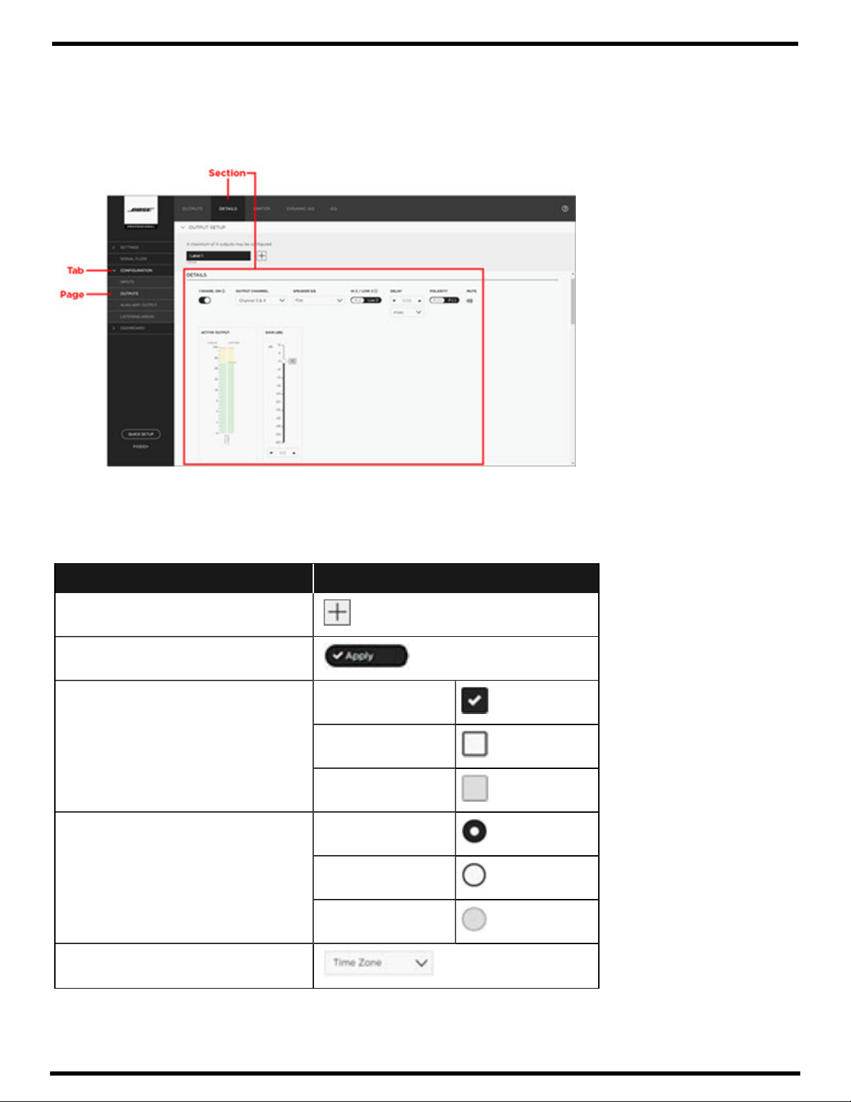
User Interface
The following illustration shows an open window in the PowerSpace+ Configuration Utility and highlights
the various elements that are available, which include tabs, pages, and sections.
Note: You can click a section heading at the top of the user interface window to quickly locate that section on the page.
User Interface Controls
The following table provides examples of the various user interface controls—and their different states, if
applicable—that you may encounter when using the PowerSpace+ Configuration Utility.
User Interface Control Example
Add button
Button
Check box
Radio button
Selected:
Not Selected:
Unavailable:
Selected:
Not Selected:
Drop-down list
Unavailable:
- 2 -
Page 6
Bose PowerSpace+ Configuration Utility User Guide
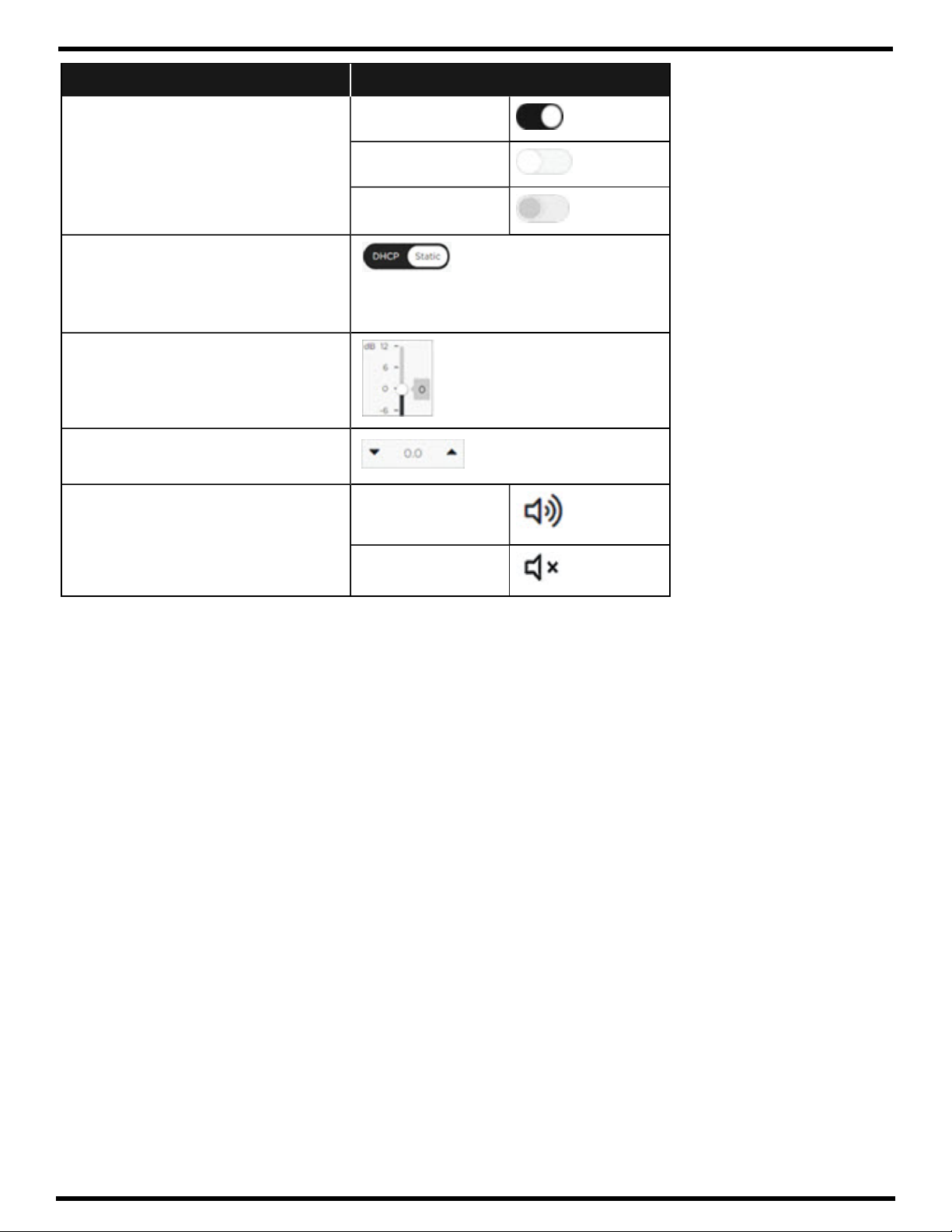
User Interface Control Example
Toggle
Labeled toggle
On:
Off:
Unavailable:
Note: In a labeled toggle, the selection
in white is the active selection.
Slider
Up and Down arrows with Text box
Mute icon Mute Off:
Mute On:
- 3 -
Page 7

Bose PowerSpace+ Configuration Utility User Guide
Quick Setup
The PowerSpace+ Configuration Utility Quick Setup is a wizard-based tool that guides you through the
initial configuration of your system.
IMPORTANT: All inputs, outputs, and I-Share jumpers (if required) must be connected, network settings
must be configured, the firmware must be up to date, and any additional amplifier settings, such as
70/100 V Hi-Z output voltage or enabling Auto Standby mode, must be configured before initiating
the wizard. These items are located on the Settings tab.
In addition, the Network page of the Settings tab allows you to configure Internet Protocol (IP) settings
for the network by selecting either DHCP (default setting) or Static in the IP Configuration toggle.
Note: You are not required to use Quick Setup to configure your system. Instead, you can click
Configuration in the left navigation panel to open the Configuration tab.
CAUTION: Running the Quick Setup wizard will reset current system settings. Except for Settings tab
configurations, any previously performed system configurations will be lost.
Starting Quick Setup
The Quick Setup wizard presents system configuration tasks in a logical sequence that mimics typical
workflow to facilitate system configuration.
Note: The amplifier automatically enters Standby mode when you start the Quick Setup wizard.
When configuration is complete, you must turn on the amplifier by either pressing the front panel
power button or disabling Standby mode on the Summary page of the Dashboard tab.
To start the Quick Setup wizard:
1. In the bottom of the left navigation pane, click Quick Setup.
The Welcome page opens and reminds you to ensure that all inputs, outputs, and I-Share jumpers
(if required) are connected and that configuration is complete on the Settings tab.
Note: If you have not already configured these settings, click the Settings tab link on the Welcome
page. When you are finished configuring the settings, click Quick Setup again to return to the wizard.
2. In the lower-right corner of the Welcome page, click Continue.
A new page opens with a warning that: "All current configuration data will be DELETED upon
pressing continue."
Note: Settings tab configurations are not deleted when you run Quick Setup.
3. Click Yes, Continue to proceed with configuration using the Quick Setup wizard (or click No, Back to
return to the previous page).
The Signal Flow page opens.
Note: You can click the Back button at any time while using the wizard to return to the previous wizard
page, or you can click Exit (at the bottom of the left navigation pane) to leave the wizard. When you click
Exit, a dialog box appears stating, "Your progress will be lost. Are you really sure that you want to exit?”
Click OK if you want to exit or click Cancel to continue using the wizard.
- 4 -
Page 8

Bose PowerSpace+ Configuration Utility User Guide
Quick Setup: Signal Flow
The Signal Flow page provides a visual overview of your system with a block diagram that illustrates the
signal flow of the system components from inputs to listening areas, and from listening areas to outputs.
This is the same diagram that appears on the Signal Flow tab.
Signal flow information can help simplify troubleshooting by providing an understanding of how a signal
travels from its source to its destination.
Click Continue to proceed to the first Inputs page of the Quick Setup Wizard.
- 5 -
Page 9

Bose PowerSpace+ Configuration Utility User Guide
Quick Setup: Inputs
The Quick Setup Inputs pages allow you to add and configure the inputs (sources) that are installed as
part of your design. You can rename each input for easy identification and inputs can be configured
independently of one another.
Note: PowerSpace+ amplifiers allow a maximum of four inputs.
To configure inputs using Quick Setup:
1. The first Inputs page lists the available input types and asks,
microphones, are in your system?”
Use the up and down arrows or type directly in the text box
to specify the number of inputs in your system and then click Continue.
2. On the next page, enter a name for the input in the Labelxtext box.
3. In the Input Channel drop-down list, select the channel that will feed the input.
4. In the Type drop-down list, select the audio input type of the selected input.
Note: For both the P4150+ and the P4300+ amplifiers:
l
Input channels 1 and 2 support balanced line-level inputs (Euroblock) or unbalanced inputs
(Stereo RCA).
l
Input channel 3 supports balanced line-level inputs (Euroblock) inputs.
l
Input channel 4 supports balanced line-level inputs (Euroblock) inputs, a 600 Ohm telephone
paging input, or a PTT/VOX (push-to-talk / voice-operated exchange) dynamic microphone
input.
“How many inputs, including
5. Select the Stereo check box (if available) if you wish to configure two input channels as a stereo pair.
Notes:
l
The Stereo check box becomes available only after you assign a channel and an appropriate
input type, and if the adjacent channel to be paired is currently unassigned.
l
Stereo can only be enabled on Euroblock input types. The Stereo check box is not available for
RCA and paging input types.
l
When the Stereo check box is enabled, the Input Channel drop-down list contains pairs of
adjacent input channels and the first available pair is automatically assigned. You can choose
a different channel pair (if available) from the Input Channel drop-down list.
l
When stereo is enabled, “Stereo” appears under the selected input's label.
6. Click the Mute icon if you wish to prevent audio from passing from the selected input to the output.
7. Click the Switch toggle (if available) to specify the paging input activation mode as
PTT (Push-to-talk) or VOX (voice-operated exchange).
IMPORTANT: The Switch option is only available for paging input types, which are only available
on the last input channel (Channel 4).
8. Click Continue.
Note: Repeat this procedure for each input in your system. The Outputs page opens after you
have finished configuring all inputs and clicked Continue.
- 6 -
Page 10

PowerShare®Configuration Utility User Guide
Quick Setup: Outputs
The Outputs pages in Quick Setup allow you to specify the number of outputs that are installed in
your system and configure them.
Note: PowerSpace+ amplifiers allow a maximum of four outputs.
To configure outputs using Quick Setup:
1. The first Outputs page asks,
arrows or type directly in the text box to specify the number of outputs in your system, and
then click Continue.
2. On the next Outputs page, enter a name for the output in the in the Labelxtext box.
3. Select the physical output channel from the Output Channel drop-down list.
4. Click the I-Share toggle (if available) if you want to enable I-Share and create an output channel
pair. I-Share output delivers twice the power level (into low-impedance (2-4Ω ) or high-impedance
(70/100V) loads) by combining the current of two output channels (channels 1 and 2, or 3 and 4).
I-Share reduces the number of available outputs because it pairs output channels.
IMPORTANT: You must ensure that I-Share jumpers are connected before enabling I-Share output
configuration mode. To view a diagram of how to wire an output pair for I-Share mode, see
Appendix B: Output and I-Share Wiring.
“How many outputs are in your system?”
Use the up and down
Note: The I-Share toggle becomes available after the Output Channel is specified, and only if the
channel to be paired with the specified channel is available. The allowable channel pairings are
channels 1 and 2, or channels 3 and 4.
5. Select an EQ from the Speaker EQ drop-down list. This setting allows you to utilize preconfigured
equalization settings (presets) for Bose®loudspeakers, specify Flat EQ, or configure Custom
EQ settings.
6. Click the Polarity toggle to set the polarity of the signal to either positive (+) or negative (-),
also referred to as non-inverted and inverted, respectively.
Note: Polarity is positive (+) by default.
7. Click Continue.
Note: Repeat this procedure for each output in your system. The Listening Areas (Routing) page
opens after you have finished configuring all outputs and clicked Continue.
- 7 -
Page 11

Bose PowerSpace+ Configuration Utility User Guide
Quick Setup: Listening Areas
The Listening Areas pages in Quick Setup allow you to add and configure listening areas based on the
distinct physical areas of your installation space.
Note: You can configure up to four independent listening areas.
To configure listening areas using Quick Setup:
1. The first Listening Areas page provides listening area examples and asks,
listening areas are in your system?”
to specify the number of listening areas, and then click Continue.
2. On the next page, enter a name for the listening area in the Areaxtext box.
3. Under Select INPUTS that will be used in this Listening Area, specify whether you want to make any
of the inputs listed in the Inputs column available for the listening area by selecting the check box.
4. Under Select OUTPUTS to route audio to this Listening Area, select the check box for any output that
you want to assign to the listening area.
Note: You can select multiple outputs for a listening area, but once an output is assigned, it is
unavailable to other listening areas.
5. In the Type drop-down list, select the type to specify whether the output is Unassigned, Mono, Left,
or Right.
Use the up and down arrows or type directly in the text box
“How many separate
Note: The Left and Right options appear when the selected input is configured as Stereo.
6. Click the up and down arrows or type directly in the Gain text box to adjust the gain. The range of
adjustment for the Gain setting is from -60 dB to +12 dB.
7. Click the Mute icon if you wish to disable audio and prevent it from passing from the selected input to
the output.
8. Click Continue.
Note: Repeat this procedure for each listening area in your system. The Quick Setup Complete page
opens after you have finished configuring all listening areas and clicked Continue.
- 8 -
Page 12

Bose PowerSpace+ Configuration Utility User Guide
Completing Quick Setup
The Quick Setup Complete wizard page lists the advanced settings that can be found on the pages of the
Configuration tab.
Click Complete to save your settings and exit the wizard.
IMPORTANT: The amplifier automatically entered Standby mode when you started the Quick Setup wiz-
ard. When configuration is complete, you must either turn on the amplifier by pressing the front panel
power button or by disabling Standby mode on the Summary page of the Dashboard tab.
Note: The Status page of the Dashboard tab appears when you have exited the wizard.
- 9 -
Page 13

Bose PowerSpace+ Configuration Utility User Guide
Settings Tab
The Settings tab includes the following pages in which you can configure basic device and network
settings, update firmware for the device, and import or export files to or from the device:
l General - Provides the amplifier model number and the ability to perform a factory reset.
l Network - IP configuration settings.
l Firmware - Version information and the ability to update the firmware.
l Import / Export - Area in which to import or export device configuration files.
l Amplifier - Options for specifying the Hi-Z constant voltage mode (70V or 100V) and mute polarity,
and enabling or disabling the Auto Standby option and output attenuators.
- 10 -
Page 14

Bose PowerSpace+ Configuration Utility User Guide
Settings: General
The General page allows you to view and reset device settings:
l Model: This setting displays the model number of the amplifier and is not configurable.
l Factory Reset: Click this button if you want to erase all current configurations and reset the amplifier
to its factory settings.
- 11 -
Page 15

Bose PowerSpace+ Configuration Utility User Guide
Settings: Network
The Network page allows you to configure Internet Protocol (IP) settings for the network by selecting
either DHCP or Static in the IP Configuration toggle.
Note: DHCP is the default network IP configuration mode. However, if your system used a DHCP router, it
is strongly recommended that the PowerSpace+ device is configured with a static IP address.
DHCP
Dynamic Host Configuration Protocol (DHCP) dynamically assigns the IP address from a DHCP server.
When you select DHCP, the IP configuration settings (IP Address, Subnet Mask, and Gateway) are
automatically set and are not configurable.
Note: No further configuration is necessary on the Settings > Network tab when DHCP is enabled.
The following procedure is only necessary if the current IP configuration mode is Static and you wish to
change it to DHCP.
To change the IP configuration mode from Static to DHCP:
1. Click DHCP on the IP Configuration toggle.
2. Click Apply.
3. In the Warning dialog box, click Continue to save the settings and restart the device, or click Cancel
to stop the process.
Note: After changing the IP configuration mode to DHCP, you must use the Bose Discovery Tool application (which you can download from bosepro.link/psasw) to reconnect to the system.
IMPORTANT: The Discovery Tool cannot identify Bose PowerSpace+ devices on Class A and Class B
networks when the computer hosting the Discovery Tool has a static IP address but no defined
subnet mask and gateway.
Link-Local IP Address (Auto IP)
If the device is set to DHCP and no DHCP server is found, such as when there is a direct connection
between the device and a laptop computer, the device will automatically assign itself a link-local IP
address (also known as Auto-IP) in the 169.254.1.0 to 169.254.254.255 range. You must open and run
the Bose Discovery Tool application to view the device's IP address.
Note: You can download the Bose Discovery Tool application from bosepro.link/psasw.
Static IP Address
Static IP address configuration allows you to manually configure a specific IP address. The IP Address,
Subnet Mask, and Gateway options become active and must be configured when you select Static.
To change the IP configuration mode from DHCP to Static:
1. Click Static on the IP Configuration toggle.
2. In the IP Address text box, enter the IP address.
3. In the Subnet Mask text box, enter the Subnet Mask address.
4. In the Gateway text box, enter the default Gateway address.
5. Click Apply.
6. In the Warning dialog box, click Continue to save the settings and restart the device, or click Cancel
to stop the process.
- 12 -
Page 16

PowerShare®Configuration Utility User Guide
Settings: Firmware
The Firmware page provides version information and allows you to use the Web UI to update the
firmware that is installed on the device. Firmware updates can include changes to (and are not
limited to) the application, amplifier firmware, the Web UI, and EQ presets.
You can view the following version information on this page:
l Web UI Version: displays the current version of the UI that is installed on the device.
l Firmware Version: displays the current version of the firmware that is installed on the device.
l EQ Version: displays the current version of the EQ file that is installed on the device.
l Bootloader Version: displays the current version of the bootloader program that is installed
on the device.
Updating Firmware
The Firmware section includes buttons that you can use to update the firmware that is installed
on the device.
To update the firmware:
1. Download the latest firmware version from bosepro.link/psasw.
Note: You must have an active internet connection to access the above link.
2. Click Select File.
3. In the Open dialog box, locate and select the firmware file that you downloaded in Step 1, and then
click Open.
The name of the file you selected appears under the Select File button.
Note: If you cannot locate the firmware file in the Open dialog box, select All files from the
drop-down list that appears to the right of the File name box.
4. Verify the selected file is correct and then click Update.
An Updating Firmware message appears in the upper-right corner of your screen. After a brief
waiting period, another message appears stating that the system will restart in a few seconds.
Next, a new window opens stating, "Trying to Reconnect to Device," and after another brief waiting
period, the PowerSpace+ Configuration Utility reopens.
Note: If you receive a Lost Connection error message, click Yes to reconnect to the system.
5. Confirm that the update was successful by verifying that the Firmware Version number on the
Firmware page is correct.
Note: When a link-local address (also known as an auto-IP address) has been previously assigned to
the device and a firmware update is performed, a new link-local address is assigned after the update
is completed and the device restarts. When this occurs, the connection is lost and cannot be recovered
automatically. You must use the Discovery Tool to rediscover the device. You must also use the
Discovery Tool if you wish to view a device's link-local address.
- 13 -
Page 17

Bose PowerSpace+ Configuration Utility User Guide
Settings: Import / Export
The Import / Export page allows you to import and export device configuration files.
Device
The Device section allows you to import (upload) configuration files to the device or export (download)
configuration files from the device.
To import a device configuration file:
1. Ensure that the file you want to import to the device is loaded onto your computer.
2. Under Device, click Import.
3. In the Open dialog box, locate and select the file to be imported, and then click Open.
Note: If you cannot locate the file in the Open dialog box, select All files from the drop-down list that
appears to the right of the File name box.
The amplifier automatically enters Standby mode (if it isn't already in that state) and one of two
messages appears depending upon whether I-Share is enabled in the imported configuration file.
- If I-Share is enabled in the imported configuration file, the following message appears:
“Verify all inputs and outputs are connected to the amplifier, as well as required I-Share jumpers.
The amplifier is in standby mode and I-Share will be enabled when the amplifier is turned on from
the front-panel power button, or by disabling standby mode in the SUMMARY tab.”
- If I-Share is not enabled in the imported configuration file, the following message appears:
“Verify all inputs and outputs are connected to the amplifier. The amplifier is in standby mode
and can be turned on from the front-panel power button, or by disabling Standby mode in the
SUMMARY tab.”
4. Click Complete.
5. If you want to take the amplifier out of Standby mode and place it into Full Power mode, do one of
the following:
- Press the Power button on the front panel.
- Disable the Standby Mode option in the PowerSpace+ Configuration Utility.
Note: If I-Share was enabled in the imported configuration file, it will remain inactive until the
amplifier is turned on.
To export a device configuration file:
1. Under Device, click Export.
2. In the lower-left corner of the browser window, right-click the exported file and select Show in folder
from the file menu.
3. In the computer's Downloads folder, locate the exported file and copy or move it to the
desired location.
- 14 -
Page 18

Bose PowerSpace+ Configuration Utility User Guide
Settings: Amplifier
The Amplifier page allows you to configure the following amplifier settings:
l Hi Z: Click either 70V or 100V in the toggle to specify the constant voltage mode for the Hi-Z
(high impedance) output of the device.
l Mute Polarity: Allows you to establish the polarity for the mute contacts on the rear panel of the
device. Click the toggle to select one of the following options:
- NO – Normally Open: indicates that the mute contacts are normally open and a short across the
mute connector will mute all outputs.
- NC – Normally Closed: inverts the mute polarity where an open circuit across the mute connector
will mute all outputs.
l Auto Standby: Click the toggle to enable or disable Auto Standby mode. When enabled, this option
automatically places the amplifier into Standby mode, allowing the system to consume less power.
When the Auto Standby option is enabled, the amplifier is automatically placed into Standby mode
when the audio signal falls below a predefined threshold (-55 dBV) for 20 minutes. The amplifier
automatically exits Standby mode (wakes), within 1 second, when an audio signal above the
threshold is detected.
CAUTION: Enabling Auto Standby is not recommended when using VOX paging because page
signals may be truncated.
Notes:
l
You can immediately place the amplifier into Standby mode by enabling the Standby Mode
option on the Summary page of the Dashboard tab.
l
For more information, see Appendix D: PowerSpace+ Amplifier Power States.
l Output Attenuators: Click the toggle to enable or disable the output attenuators on the rear panel
of the amplifier. When Disabled is selected, the output attenuation is locked at its current level.
- 15 -
Page 19

Bose PowerSpace+ Configuration Utility User Guide
Signal Flow Tab
The Signal Flow tab provides a visual overview of your system with a block diagram that illustrates the
signal flow of your system components from inputs to listening areas, and from listening areas to outputs.
Signal flow information can help simplify troubleshooting by providing an understanding of how a signal
travels from its source to its destination.
- 16 -
Page 20

Bose PowerSpace+ Configuration Utility User Guide
Configuration Tab
The Configuration tab includes pages in which you can configure inputs, outputs, auxiliary outputs
(Music on Hold and line-level output), and listening areas (routing).
IMPORTANT: All inputs, outputs, and I-Share jumpers (if required) must be connected, network settings
must be configured, the firmware must be up to date, and any additional, optional amplifier settings, such
as 70/100 V Hi-Z output voltage or enabling Auto Standby mode, must be specified before configuring
the system. These items are located on the Settings tab.
- 17 -
Page 21

Bose PowerSpace+ Configuration Utility User Guide
Configuration: Inputs
The Inputs page allows you to add, remove, and configure inputs (sources). Each input can be named
for easy identification and inputs can be configured independently of one another.
Note: PowerSpace+ amplifiers allow a maximum of four inputs.
Input Setup
The Input Setup area lists any existing inputs and allows you to add a new input, edit the name of an
input, or delete an input.
To add an input:
l
Under Input Setup, click Add , and then edit the input name (described below).
Note: The Add button becomes unavailable after the maximum number of inputs is reached.
To edit the name of an input:
1.
Under Input Setup, in the text box that contains the input name that you want to edit, click Edit.
Note: The Edit icon appears when you hover over the text box.
2. Type a new name for the input and then press Enter.
To delete an input:
1. Under Input Setup, in the text box that contains the name of the input that you want to delete,
click Delete.
Note: The Delete icon appears when you hover over the text box, and only when at least two
inputs exist.
2. In the Warning dialog box, click Yes to remove the input, or click No to cancel the process.
Details
The Details section of the Inputs page allows you to configure certain settings for the selected input.
Settings vary depending upon the input type.
To configure details for an input:
Under Input Setup (at the top of the page), click the name of the input you want to configure, if
it is not already selected.
Note: When selected, the input name box appears as white text on a black background.
You can then configure the following settings as applicable:
l Stereo: You can configure input channels as stereo pairs by selecting the Stereo check box.
This allows you to assign a pair of adjacent input channels by selecting the pair (channels 1 and 2,
or channels 3 and 4) from the Input Channel drop-down list. Clear the Stereo check box if you
want to configure the input as mono.
Notes:
l
The Stereo check box becomes available only after you assign a channel and an appropriate
input type, and if the adjacent channel to be paired is currently unassigned.
l
Stereo can only be enabled on Euroblock input types. The Stereo check box is not available for
RCA and paging input types.
l
When the Stereo check box is enabled, the Input Channel drop-down list contains pairs of
adjacent input channels and the first available pair is automatically assigned. You can choose
- 18 -
Page 22

Bose PowerSpace+ Configuration Utility User Guide
a different channel pair (if available) from the Input Channel drop-down list.
l
When stereo is enabled, “Stereo” appears under the selected input's label.
l Input Channel: Select the physical input channel from the Input Channel drop-down list.
l Type: Select the audio input type that you want to assign to the selected input from the Type
drop-down list. For both the P4150+ and the P4300+ amplifiers:
- Input channels 1 and 2 support balanced line-level inputs (Euroblock) or unbalanced inputs
(Stereo RCA).
- Input channel 3 supports balanced line-level inputs (Euroblock) inputs.
- Input channel 4 supports balanced line-level inputs (Euroblock) inputs, a 600 Ohm telephone
paging input, or a PTT/VOX (push-to-talk / voice-operated exchange) dynamic microphone input.
l Active Input meter: Provides a current visual representation of the signal level (in dBFS) for the
selected input.
Note: When Stereo is enabled, the Active Input meter displays the two channels that are paired for
the selected input.
l Gain (dB) adjuster: Allows you to move the slider to adjust the input signal level in the -60 to
+12 dB range.
Note: You can use the slider, the up and down arrows, or type directly in the Gain text box to adjust
the gain.
l Mute: Click the Mute icon that appears under the Gain slider if you want to disable audio and prevent
it from passing from the selected input to the output.
l Tone EQ adjusters: Allows you to move the sliders to adjust the Low, Mid, and High Tone EQ levels in
the -15 dB to +15 dB range.
Note: You can use the sliders, the up and down arrows, or type directly in any of the Tone EQ text
boxes to adjust the Tone EQ.
l Threshold (dB) adjuster: This setting appears only when the selected input is used for VOX paging
(see the Push To Talk / Voice Operated option description below) and allows you to move the slider
to adjust the threshold of a paging input in the -60 dB to +0 dB range.
l Push To Talk / Voice Operated: This option appears only if the selected input is used for paging.
Click either PTT or VOX in the toggle to specify the paging input activation mode.
l Opti-voice EQ: This option appears only if the selected input is used for paging. Opti-voice equalizes
the vocal frequency range for clear speech intelligibility and provides a smooth transition between
music and announcement. Click the toggle to enable or disable Opti-voice for the selected input.
- 19 -
Page 23

Bose PowerSpace+ Configuration Utility User Guide
Configuration: Outputs
The Outputs page includes sections in which you can add, remove, and configure outputs based on your
design. Each output can be named for easy identification and outputs can be configured independently of
one another.
Notes:
l
PowerSpace+ amplifiers allow a maximum of four outputs.
l
You can click the tabs at the top of the Outputs page to quickly locate a specific section.
Output Setup
The Output Setup section lists all existing outputs and allows you to add or delete an output, and edit the
name of an output, if necessary.
To add an output:
l
Under Output Setup, click Add , and then edit the output name (described below).
Note: The Add button becomes unavailable after the maximum number of outputs is reached.
PowerSpace+ amplifiers allow a maximum of four outputs.
To edit the name of an output:
1.
Under Output Setup, in the text box that contains the output name that you want to edit, click Edit.
Note: The Edit icon appears when you hover over the text box.
2. Type a new name for the output and then press Enter.
To delete an output:
1. Under Output Setup, in the text box that contains the name of the output that you want to delete,
click Delete.
Note: The Delete icon appears when you hover over the text box, and only when at least two
outputs exist.
2. In the Warning dialog box, click Yes to remove the output, or click No to cancel the process.
Details
The Details section allows you to configure outputs, including specifying the physical output channel and
the loudspeaker EQ settings.
To configure details for an output:
Under Output Setup (at the top of the page), click the name of the output you want to configure, if it is
not already selected.
Note: When selected, the output name box appears as white text on a black background.
You can then configure the following settings as applicable:
l I-Share: Click the toggle (if available) to enable or disable I-Share output configuration mode. I-Share
output delivers twice the power level (into low-impedance (2-4 Ω ) or high-impedance (70/100V)
loads) by combining the current of two output channels (channels 1 and 2, or 3 and 4). I-Share reduces
the number of available outputs because it pairs output channels.
IMPORTANT: You must ensure that I-Share jumpers are connected and that the amplifier is in Standby
mode before enabling I-Share output configuration mode. To view a diagram of how to wire an output
pair for I-Share mode, see Appendix B: Output and I-Share Wiring.
- 20 -
Page 24

Bose PowerSpace+ Configuration Utility User Guide
Note: The I-Share toggle becomes available after the Output Channel is specified, and only if the
channel to be paired with the specified channel is available. The allowable channel pairings are
channels 1 and 2, or channels 3 and 4.
When you click the toggle to enable I-Share, the Enable I-Share dialog box appears in which you must
select one of the following options:
- Full Power to enable I-Share and go into Full Power mode.
- Standby to keep the amplifier in Standby Mode where configuration can continue. I-Share will be
enabled when the amplifier is turned on by the front panel power button or by disabling Standby
mode on the Summary page of the Dashboard tab.
Note: If at any time you want to disable I-Share, when you click the toggle, the Disable I-Share dialog
box appears to inform you that the amplifier has to enter Standby mode to complete the process.
Click Enter Standby to proceed with disabling I-Share or click Cancel to keep I-Share enabled.
l Output Channel: Select the physical output channel for the selected output from the drop-down list.
l Speaker EQ: Allows you to select from among the following loudspeaker EQs for the selected output:
- Flat EQ settings
- Custom EQ settings
- Bose®loudspeakers, which include preconfigured equalization settings (presets).
l HI Z / Low Z: Click the toggle to select either high impedance (Hi Z) or low impedance (Low Z).
Note: If you select Hi Z, you can specify the constant voltage mode as 70V or 100V under
Amplifier Settings on the Amplifier page of the Settings tab.
l Delay: Allows you to set the signal delay time by first specifying a number using the up and
down arrows or typing directly in the text box, and then selecting the measurement type from
the drop-down list. Measurement types include milliseconds (msec), meters, and feet.
l Polarity: Allows you to change the polarity of the signal to positive (+) or negative (-), which are also
referred to as non-inverted and inverted, respectively. Polarity is positive (+) by default.
l Mute: Click the Mute icon to enable or disable muting for the output channel.
l Active Output meter: Displays the current output signal level as a Vpeak measurement with a
range of 0 to 160.
Note: When I-Share is enabled, the Active Output meter displays two amplifier channels for the
selected output.
l Gain (dB) adjuster: Allows you to adjust the output signal level delivered to the next gain stage. The
range of adjustment is from –60 to +12 dB.
Note: You can use the slider, the up and down arrows, or type directly in the text box to adjust the
gain.
- 21 -
Page 25

Bose PowerSpace+ Configuration Utility User Guide
Limiter
The Limiter section enables you to specify both peak and RMS voltage limiting for loudspeaker driver
protection.
Note: Unless stated otherwise, the following Limiter settings are configurable only when the Low Z setting
is selected and the Speaker EQ setting is Flat or Custom. When you select a Bose loudspeaker, the Lim-
iter settings are specific to that loudspeaker and are visible but cannot be adjusted.
l Threshold (V): Allows you to set limits on the final output-level loudspeaker protection. Click the up
and down arrows or type directly in the text box(es) to specify:
- VPeak: Determines the maximum signal level allowed to pass through the signal processing
block. Input signal levels above the threshold will be reduced (or hard-limited) to the VPeak
threshold value.
- VRMS: Determines the maximum continuous RMS signal level allowed to pass unaltered through
the signal processing block. Input signal levels above the threshold level will be reduced to the
RMS threshold value.
l Attack (ms): Allows you to specify (in milliseconds) how quickly the signal is limited after it exceeds
the threshold.
- VPeak: This setting is not configurable.
- VRMS: Click the up and down arrows or type directly in the text box to specify the amount of time
an RMS signal must exceed the RMS threshold level before the gain of the signal is reduced.
l Release (ms): Allows you to specify (in milliseconds) the amount of time it takes to stop limiting the
signal after it goes below the threshold.
- VPeak: This setting is not configurable.
- VRMS: Click the up and down arrows or type directly in the text box to specify the amount of time
the input signal continues to be reduced after the detection signal drops below the RMS
threshold setting.
Dynamic EQ
Click the Dynamic EQ toggle to enable dynamic equalization for the selected loudspeaker. Dynamic EQ
monitors the low-frequency output of select loudspeakers and compensates for a perceived loss of bass
response at low listening levels. After enabling Dynamic EQ, you must calibrate the signal to set the
threshold level.
To calibrate the signal for Dynamic EQ:
1. Click Calibrate.
Notes:
l
The Calibrate button becomes active when Dynamic EQ is enabled via the Dynamic EQ toggle.
l
As a best practice, place yourself in the typical listening position for the output you are calibrating.
- 22 -
Page 26

Bose PowerSpace+ Configuration Utility User Guide
The following dialog box appears and the system will play pink noise:
2. Use an A-weighted SPL (sound pressure level) meter and click the up and down arrows or type
directly in the text box to adjust the calibration level until the SPL meter reads 70 dB-SPL.
3. When you are finished, click Complete.
EQ
The EQ section allows you to adjust up to 9-band EQ settings for selected outputs by entering the
desired filter values for type, frequency, gain, Q, and bandwidth.
Note: EQ settings are only configurable when you select Custom as the Speaker EQ setting. If you select
Flat, the EQ settings are not configurable. If you select a Bose loudspeaker from the Speaker EQ
drop-down list, the EQ settings are not configurable because they are already included in Bose
loudspeaker presets.
The following settings are configurable only when you select Custom as the Speaker EQ setting:
l Graphical display: EQ is represented graphically with the X axis representing the frequency range of
20 Hz to 20 kHz, and the Y axis representing the range of gain adjustment from -20 dB to 20 dB.
Click a numbered filter node in the graph to enable or disable the filter. You can click on the
nodes in the graph to enable or disable filters, and you can move the nodes within the graph to
adjust the settings that appear in the Filters table (described below).
Note: The icon is blue when the filter is enabled.
l Reset All: Click Reset All (located above the right side of the graph) to return all EQ settings to their
default values in both the graph and the Filters table.
l High Pass / Low Pass table: Allows you to enable (or disable) and configure High Pass and Low Pass
EQ filters for the selected output, as follows:
- HighPass: Click the icon to enable or disable the High Pass filter, which attenuates all signals
below the specified frequency.
- LowPass: Click the icon to enable or disable the Low Pass filter, which attenuates all signals
above the specified frequency.
Note: The icon is blue when the filter is enabled.
- Frequency (Hz): Click the up and down arrows or type directly in the text box to specify the
frequency in hertz where the High Pass or Low Pass filter is applied.
- 23 -
Page 27

Bose PowerSpace+ Configuration Utility User Guide
- Type: Select a Butterworth filter type from the drop-down list to adjust the slope of the attenuation
curve when using High Pass or Low Pass filters. The following Butterworth filter types are available:
l Butterworth 6 (+/-6 dB/Oct)
l Butterworth 12 (+/-12 dB/Oct)
l Butterworth 18 (+/-18 dB/Oct)
l Butterworth 24 (+/-24 dB/Oct)
- Reset: Click Reset to return all settings for the filter (in that row) to their default values.
l Filters table: Allows you to enable or disable filters and to adjust the selected output’s 9-band EQ.
- Filters: Click a numbered icon in the Filters column to enable or disable the filter.
Note: The icon is blue when the filter is enabled.
- Type: Select the filter type from the drop-down list. Available filter types differ according to the
filter number and may include:
l PEQ: Boosts and cuts the signal in the vicinity of the specified frequency.
l Notch: Attenuates the signal at the specified frequency.
l HighShelf: Boosts and cuts the signal above the specified frequency.
l LowShelf: Boosts and cuts the signal below the specified frequency.
- Frequency (Hz): Click the up and down arrows or type directly in the text box to specify the
frequency in hertz where the filter is applied. The range for this setting is 20 Hz to 20 kHz.
- Gain (dB): Click the up and down arrows or type directly in the text box to specify how much the
filter cuts (reduces the signal at) the frequency band. The range for this setting is -20 dB to 20 dB.
Note: The Gain setting is not available when the selected filter type is Notch.
- Q: Click the up and down arrows or type directly in the text box to specify the "quality factor,"
which is the ratio of center frequency to bandwidth. The range for this setting is .10 to 10.
Note: The Q setting is linked to the Bandwidth (Oct) setting such that increasing Q decreases
bandwidth, and decreasing Q increases bandwidth.
- Bandwidth (Oct): Click the up and down arrows or type directly in the text box to specify the
octave bandwidth of the filter.
Note: The Bandwidth (Oct) setting is linked to the Q setting such that increasing bandwidth
decreases Q, and decreasing bandwidth increases Q.
- Reset: Click Reset to return all settings for the filter (in that row) to their default values.
- 24 -
Page 28

Bose PowerSpace+ Configuration Utility User Guide
Configuration:Auxiliary Output
PowerSpace+ amplifiers include two additional, independent (auxiliary) outputs that you can configure on
the Auxiliary Output page of the Configuration tab:
l Music On Hold (MOH): Dedicated 600 Ohm music-on-hold interface for simple integration into a
phone system.
l Line Level Output: Line-level auxiliary output.
Music On Hold
The dedicated 600-Ohm Music on Hold (MOH) interface provides simple integration into a PBX phone
system and allows you to play music from a selected source over a phone line while a caller is on hold.
You can configure the following Music on Hold settings:
l Enable Transformer (600 Ω): Click the toggle to enable or disable the output-balancing transformer
for MOH.
l Gain: Click the up and down arrows or type directly in the text box to specify the gain within the -16.0
to +16.0 range (in 0.5 dB increments).
l Input: Select the MOH input source from the drop-down list.
Line Level Output
The line-level auxiliary output enables you to route the signal to additional audio equipment.
You can configure the following Line Level Output settings:
l Enable Aux Line Out: Click the toggle to enable or disable the line-level auxiliary output.
l Gain: Click the up and down arrows or type directly in the text box to specify the gain within the -16.0
to +16.0 range (in 0.5 dB increments).
l Input: Select the input source that you wish to use for the auxiliary output from the drop-down list.
- 25 -
Page 29

Bose PowerSpace+ Configuration Utility User Guide
Configuration:Listening Areas
The Listening Areas page allows you to add, remove, and configure listening areas (zones) based on the
physical areas of your installation space. Listening areas can be named for easy identification and can be
configured independently of one another.
Notes:
l
You can configure up to four independent listening areas.
l
You can click the tabs at the top of the Listening Areas page to quickly locate a specific section.
Listening Areas
This Listening Areas section lists any existing listening areas and allows you to add a new listening area,
edit the name of a listening area, or delete a listening area.
To add a listening area:
l
At the top of the page under Listening Areas, click Add , and then edit the listening area name
(described below).
Note: The Add button becomes unavailable after a fourth listening area is added.
To edit the name of a listening area:
1. Under Listening Areas, in the box that contains the name of the listening area that you want to edit,
click Edit.
Note: The Edit icon appears when you hover over the text box.
2. Type a new name for the listening area and then press Enter.
To delete a listening area:
1. Under Listening Areas, in the box that contains the name of the listening area that you want to delete,
click Delete.
Note: The Delete icon appears when you hover over the text box, and only when at least two listening
areas exist.
2. In the Warning dialog box, click Yes to remove the listening area, or click No to cancel the process.
Configuring a Listening Area
Under Listening Areas, click the name of the listening area you want to configure. When selected, the
listening area name box appears as white text on a black background. You can then configure controllers,
routing details, area gain, area EQ, and area paging settings, as applicable.
Area Controller
The Bose CC-1, CC-2 , and CC-3 Zone Controllers are a series of wall-mounted interfaces that are
engineered to provide custom on-site volume controls.
l CC-1 provides volume control
l CC-2 provides volume control and A/B source selection
l CC-3 provides volume control and A/B/C/D source selection
Click the Controllers toggle if you wish to enable a controller for the selected listening area. When you
enable a controller for a listening area, you must also specify:
- 26 -
Page 30

Bose PowerSpace+ Configuration Utility User Guide
l Type: Select the controller model from the drop-down list.
l Controller: Select the DIP switch identification number from the drop-down list. For more information,
see Appendix C: ControlCenter Analog Zone Controller DIP Switch Configuration.
Routing Details
The Routing Details section allows you to enable and select controllers, specify sources, and select
outputs for the selected listening area.
l Select INPUTS: The left side of the Routing Details section contains the settings that you can
configure to select the inputs that are available to play in the selected listening area.
- Inputs: This column lists the available inputs for the selected listening area. This column is
not configurable.
- Select: Select the check box that appears in the same row as the input that you want to use in the
selected listening area. You can select multiple inputs.
- Switch: The settings in this column vary depending upon whether a controller is enabled for the
listening area and if so, the specified controller type.
Switch settings are not available (N/A) for a CC-1 controller, but if the controller type is CC-2 or
CC-3, you must select a check box to assign a switch to the selected input for source selection.
The available Switch settings for a CC-2 controller are A and B, and the available Switch settings
for a CC-3 controller are A, B, C, and D.
Note: CC-2 and CC-3 controller configurations will be ignored if their Switch settings are
not selected.
l Select OUTPUTS: The right side of the page contains the settings that allow you to select and
configure the outputs within the selected listening area.
- Outputs: This column lists the outputs that may be selected and configured for the selected
listening area. This column is not configurable.
- Select: Select the check box that appears in the same row as the output that you want to assign to
the listening area. You can then specify the type, gain, and whether to mute the selected output.
- Type: Specifies whether the output is Unassigned, Mono, Left, or Right.
Notes:
l
The Left and Right options appear when the selected input is configured as Stereo.
l
Outputs designated as Left and Right will play back Mono signals if a Controller adjusts the
selected input to a Mono source.
- Gain: Specifies the gain for the output in the selected listening area.
Note: You can use the up and down arrows or type directly in the text box to adjust the gain.
- Mute: Enables or disables muting for the output in the selected listening area.
Area Gain
The Area Gain section allows you to specify the following settings for the selected listening area:
l Area Gain (dB): Specifies the output volume level for the selected listening area.
Note: Area Gain does not adjust area paging.
l Area Mute: Enables or disables muting in the selected listening area.
Area EQ
The Area EQ section allows you to enable or disable filters and adjust the 7-band EQ settings for the
selected listening area by entering the desired filter values for type, frequency, gain, Q, and bandwidth.
- 27 -
Page 31

Bose PowerSpace+ Configuration Utility User Guide
l Graphical display: Area EQ is represented graphically with the X axis representing the frequency
range of 20 Hz to 20 kHz, and the Y axis representing the range of gain adjustment from -20 dB
to 20 dB. Click a filter node in the graph to enable or disable the filter. You can click on the
nodes
in the graph to enable or disable filters, and you can move the nodes within the graph to adjust the
settings that appear in the Filters table (described below).
Note: The icon is blue when the filter is enabled.
l Reset All: Click Reset All (located above the right side of the graph) to return all Area EQ settings to
their default values in both the graph and the Filters table that appears under the graph.
The Filters table allows you to enable/disable and configure EQ filters for the selected listening area.
l
Filters: Click a numbered icon in the Filters column to enable or disable the filter.
Note: The icon is blue when the filter is enabled.
l Type: Select the filter type from the drop-down list. Available types include:
- High Pass: Attenuates the signal below the specified frequency. This filter type is available
only on the first filter.
- Low Pass: Attenuates the signal above the specified frequency. This filter type is available
only on the last filter.
- PEQ: Boosts and cuts the signal in the vicinity of the specified frequency. This filter type is
available on all filters.
- Notch: Attenuates the signal at the specified frequency. This filter type is available only
on filters 2-6.
- HighShelf: Boosts and cuts the signal above the specified frequency. This filter type is
available only on filters 2-6.
- LowShelf: Boosts and cuts the signal below the specified frequency. This filter type is
available only on filters 2-6.
l Frequency (Hz): Click the up and down arrows or type directly in the text box to specify the
frequency in hertz where the filter is applied.
l Gain (dB): Click the up and down arrows or type directly in the text box to specify how much
the filter cuts (reduces the signal at) the frequency band.
Note: This setting is available only when the selected filter type is PEQ, HighShelf, or LowShelf.
l Q: Click the up and down arrows or type directly in the text box to specify the "quality factor,"
which is the ratio of center frequency to bandwidth.
Note: This setting is not available for the High Pass and Low Pass filter types. Q is also linked
to the Bandwidth (Oct) setting such that increasing Q decreases bandwidth, and decreasing
Q increases bandwidth.
l Bandwidth (Oct): Click the up and down arrows or type directly in the text box to specify the octave
bandwidth of the filter.
Note: This setting is not available for the High Pass and Low Pass filter types. Bandwidth is also linked
to the Q setting such that increasing bandwidth decreases Q, and decreasing bandwidth increases Q.
Area Paging
The Area Paging section allows you to enable (or disable) and configure paging for the selected listening
area. Click the Paging toggle to enable or disable paging for the selected listening area. When paging is
enabled, you can configure the following settings:
- 28 -
Page 32

Bose PowerSpace+ Configuration Utility User Guide
l Paging Gain (dB): Click the up and down arrows or type directly in the text box to specify the gain
level of the paging signal. The range for this setting is -60 dB to 12 dB.
l Ducking Depth (dB): Click the up and down arrows or type directly in the text box to set the amount
of attenuation to be applied to the original source signal. The range for this setting is -60 dB to 0 dB.
l Hold Time: Click the up and down arrows or type directly in the text box to specify the amount of
time (in milliseconds) to continue attenuation after the paging source signal is discontinued.
The range for this setting is 0 ms to 1000 ms.
l Release Time: Click the up and down arrows or type directly in the text box to specify the amount of
time (in milliseconds) it will take to return to the original source signal after the Hold Time has
expired. The range for this setting is 1 ms to 2000 ms.
- 29 -
Page 33

Bose PowerSpace+ Configuration Utility User Guide
Dashboard
The Dashboard tab includes pages that provide a high-level system overview and allow you to quickly
view source (input) and output activity across all configured listening areas.
To view the Dashboard:
1. In the left pane, click Dashboard to expand the menu.
2. Select the Status or Summary page of the Dashboard tab, depending upon the type of information
you want to view:
- The Status page provides a visual overview of the inputs and outputs in a listening area.
- The Summary page provides a visual overview of the entire system.
- 30 -
Page 34

Bose PowerSpace+ Configuration Utility User Guide
Dashboard: Status
The Status page of the Dashboard tab provides a real-time account of the inputs and outputs for each of
the listening areas that are configured in your system:
l Listening area name: Shows the name of the listening area.
l Paging: Indicates whether paging is turned on in the listening area.
l Listening area meters: Identify the inputs and outputs that are currently working within the selected
listening area and shows their status via the following meters:
- Available Inputs: Displays real-time metering for each input channel associated with a
listening area.
- Outputs: Displays real-time metering for each output channel associated with a listening area.
- 31 -
Page 35

Bose PowerSpace+ Configuration Utility User Guide
Dashboard: Summary
The Summary page of the Dashboard tab is a visualization tool that provides a real-time account of the
overall system status.
The system information provided on this page includes:
l Live Meter: When the device is in Full Power mode, provides a real-time temperature measurement
within a color-coded range that is dependent upon the internal temperature measurement and
fan speed.
Color: Indicates: Conditions:
Green Safe Operating Zone Low temperatures and low fan speed
Yellow Thermal Warning Zone Hotter operation and mid fan speed
Red Thermal Fault - Amp Muted Highest fan speed, amp outputs are muted (protection mode)
l Standby Mode: When enabled, this function immediately enters the amplifier into a power-saving
state (Standby), allowing the system to consume less power. Click the Standby Mode toggle to
enable Standby mode, or disable it and immediately place the amplifier into Full Power mode.
Notes:
l
When Standby mode is enabled, the meter shows the last temperature reading when the device
was in Full Power mode (before Standby mode was enabled).
l
You can configure the amplifier to automatically enter and exit Standby mode by enabling the
Auto Standby option on the Amplifier page of the Settings tab.
l
For more information, see Appendix D: PowerSpace+ Amplifier Power States.
l Inputs: Provides a visual summary of the inputs that are configured in your system.
- Signal: Replicates the Input Signal LEDs on the front of the amplifier. Each LED is associated with a
single input and uses color-coded status indicators.
Color: Indicates:
Gray No input signal / Off
Green Signal is present
Amber Signal is near clipping
Red Signal is clipping
- Input Meters: Provides a current visual representation of the signal level for all inputs in the system.
l Outputs: Provides a visual summary of all outputs that are configured in your system.
- Limiters: Provide a current visual representation of the status of the
Power and Loudspeaker limiters.
l Power: Replicates the Output Limit LEDs on the front of the amplifier. Each LED is associated
with an output and uses color-coded status indicators.
Color: Indicates:
Gray Off
Amber Amplifier is limiting output (power)
Red (Solid) Fault
Red (Blinking) Amplifier is muted
- 32 -
Page 36

Bose PowerSpace+ Configuration Utility User Guide
l Loudspeaker: Indicates voltage limiting on output and uses color-coded status indicators.
Color: Indicates:
Gray Off
Amber Amplifier is limiting output (loudspeaker)
- Output Meters: Provides a current visual representation of the signal level for all outputs in
the system.
l Fault Log: Provides a record of faults that have occurred in the system. The Fault Log includes
two tabs:
- Fault Log: Lists only active faults to a maximum of 10. This tab includes the Clear Active Fault Log
button, which allows you to manually move active faults from the Fault Log tab to the
Fault Log History tab.
- Fault Log History: Lists inactive faults and any faults that have been manually moved from the
Fault Log tab, to a maximum of 50. This tab includes the Download button, which allows you to
download and save a copy of the log in a .csv file.
Note: A fault is automatically moved from the Fault Log tab to the Fault Log History tab when the
fault is cleared by the amplifier, for example, after a power cycle.
- 33 -
Page 37

Bose PowerSpace+ Configuration Utility User Guide
Appendix A: Audio and Control Connections
The P4300+ and P4150+ include two types of analog inputs for audio devices: summed mono RCA connectors and balanced Euroblock connectors. A mono RCA input into input 1 (red or white) and/or input 2
(red or white) are acceptable mono audio sources.
The following diagrams show the recommended balanced/unbalanced wiring between the Euroblock
audio connectors on the amplifier and common audio connectors to external audio components.
Connecting Analog Audio Devices
Use the included green 3-pin Euroblocks to connect to the inputs, or use the orange 3-pin Euroblocks to
connect to the 600 Ohm music-on-hold auxiliary output or the line-level auxiliary output.
Dynamic Microphone Connection
Input 4 of the P4300+ and P4150+ can accept either a line-level source (default), a PTT/VOX dynamic
microphone, or interface to a 600 Ohm telephone paging system. You can change the input type from the
default in the web-served UI. Use the included green 4-pin Euroblock to make this connection.
- 34 -
Page 38

Bose PowerSpace+ Configuration Utility User Guide
600 Ω Telephone Paging Connection
The default telephone paging activation method is VOX (voice activated). The telephone paging stimulus
can be changed to PTT (push-to-talk) in the web-served UI. Connect the Push-to-Talk contact to the PTT
pin of input 4. Use the included green 4-pin Euroblock to make this connection.
Mute with Standard Contact Closure
The P4300+ and P4150+ are designed to mute all outputs when the Mute
contacts are either shorted together or opened, depending on how the amplifier is configured.
The default state is Normally Open (NO), where a short across the mute connector will mute all outputs. Using the integrated web server, the mute polarity can be inverted to Normally Closed (NC), where an open across the
mute connector will mute all outputs.
Use the included black 2-pin Euroblock to make this connection.
Note: All Limit LED indicators will blink red when the amplifier is muted from software or from the rear
panel Mute connector.
Connecting to a Network
The P4300+ and P4150+ include an RJ-45 Ethernet port on the rear panel for network connection.
Use a foiled or unshielded twisted-pair (F/UTP) Cat 5e cable (not included) to connect this port
on each amplifier to your network or computer. Make this connection directly to the
amplifier or through a switched Ethernet network.
Note: All PowerSpace+ amplifiers are set to DHCP, which you can change by using the web-served UI.
- 35 -
Page 39

Bose PowerSpace+ Configuration Utility User Guide
Appendix B: Output and I-Share Wiring
Output Wiring
Use the included terminal forks to crimp 14-16 gauge wires for loudspeaker connections to the amplifiers'
output terminal block. Ten terminal forks are included with each P4300+ and P4150+ amplifier, leaving
two extra terminal forks.
I-Share Wiring
I-Share outputs deliver twice the channel power level by combining the current of two channels. Each output pair of a Bose PowerSpace P4300+ or P4150+ amplifier can be I-Shared by adding the included
jumper accessory and enabling I-Share in the web-served UI.
The following diagram illustrates the necessary I-Share wiring. Wire the I-Share 1 & 2 loudspeaker load to
the amplifier using terminals 1+ and 1– (or 2+ and 2–). Wire the I-Share 3 & 4 loudspeaker load to the amplifier using terminals 3+ and 3– (or 4+ and 4–).
Output Attenuators
Output attenuation controls are available for each output. Turn the controls clockwise to decrease attenuation, or counterclockwise to increase attenuation. The attenuator must be at 0 dB attenuation for the
respective output to reach rated power.
- 36 -
Page 40

Bose PowerSpace+ Configuration Utility User Guide
Appendix C: ControlCenter Analog Zone Controller DIP Switch Configuration
When connecting to a PowerSpace+ amplifier, use the following DIP switch settings to configure ControlCenter analog zone controllers.
Up to four controllers can be connected directly to an amplifier's ControlCenter RJ-45 connector by
daisy-chaining controllers, or by using the Bose ControlCenter CV41 4-to-1 Converter.
The CC-1 DIP switches assign an ID that must match the ID of the controller that is assigned to the listening area in the UI. Each CC-1 controller requires DIP switch 3 to be ON. Only one of the DIP switches 5, 6, 7,
or 8 must be ON to match the ID assigned to the listening area in the UI. Set DIP switch 5 to ON for ID 1,
DIP switch 6 to ON for ID 2, DIP switch 7 to ON for ID 3, or DIP switch 8 to ON for ID 4.
CC-1 Controllers
One CC-1 controller:
This single CC-1 is configured as ID 1.
Two CC-1 controllers:
CC-1 #1 is configured as ID 1 and CC-1 #2 is configured as ID 2.
Three CC-1 controllers:
CC-1 #1 is configured as ID 1, CC-1 #2 is configured as ID 2, and CC-1 #3 is configured as ID 3.
Four CC-1 controllers:
CC-1 #1 is configured as ID 1, CC-1 #2 is configured as ID 2, CC-1 #3 is configured as ID 3, and CC-1 #4 is
configured as ID 4.
- 37 -
Page 41

Bose PowerSpace+ Configuration Utility User Guide
CC-2 Controllers
Up to two CC-2 controllers can be connected directly to an amplifier by daisy-chaining controllers, or by
using the ControlCenter CV41 4-to-1 Converter.
The CC-2 DIP switches assign an ID that must match the ID of the controller that is assigned to the listening area in the UI.
Note: The CC-2 controller can only be configured as ID 1 or ID 2.
One CC-2 controller:
This single CC-2 is configured as ID 1 with DIP switches 1, 3, and 5 ON.
Two CC-2 controllers:
CC-2 #1 is configured as ID 1 with DIP switches 1, 3, and 5 ON and CC-2 #2 is configured as ID 2 with DIP
switches 2, 4, and 6 ON.
Note: DIP switches 7 and 8 are not used on the CC-2.
CC-3 Controller
Only one CC-3 controller can be connected to an amplifier and there are no DIP switches to set.
CC-1 and CC-2 Controller Combinations
Up to four controllers can be connected directly to an amplifier by daisy-chaining controllers, or by using
the ControlCenter CV41 4-to-1 Converter.
One CC-1 controller and one CC-2 controller:
CC-1 is configured as ID 1 and CC-2 as ID 2. The ID configurations can also be swapped where the CC-2 is
ID 1 and the CC-1 is ID 2.
Two CC-1 controllers and one CC-2 controller:
- 38 -
Page 42

Bose PowerSpace+ Configuration Utility User Guide
The CC-2 must be either ID 1 or ID 2 in this configuration. CC-1 #1 is configured as ID 1, CC-2 as ID 2, and
CC-1 #2 as ID 3.
One CC-1 controller and two CC-2 controllers:
The two CC-2s must be ID 1 and ID 2 in this configuration. CC-2 #1 is configured as ID 1, CC-2 #2 as ID 2,
and the CC-1 as ID 3.
Three CC-1 controllers and one CC-2 controller:
The CC-2 can only be ID 2 in this configuration. CC-1 #1 is configured as ID 1, CC-2 as ID 2, CC-1 #2 as ID 3,
and CC-1 #3 as ID 4.
- 39 -
Page 43

Bose PowerSpace+ Configuration Utility User Guide
Appendix D: PowerSpace+ Amplifier Power States
Bose PowerSpace+ amplifiers have three possible power states:
Power State: LED Status:
Full Power mode (ON) Power LED is solid white.
Standby mode Power LED and all other LEDs are off.
Auto Standby mode Power LED blinks white.
Note: By default, Standby mode is the initial power state of a PowerSpace+ amplifier when it is
plugged in for the first time.
Standby Mode Options
Standby mode places the amplifier into a power-saving state, allowing the system to consume less
power. You can use the following methods to place the amplifier into Standby mode:
Power State Operation
Full Power mode (ON) When the amplifier is in Full Power mode, you can do one of the following to
immediately place the amplifier into Standby mode:
l Press the Power button on the front panel.
l Enable the Standby Mode option in the PowerSpace+ Configuration Utility.
Standby mode The amplifier is immediately placed into Standby mode when the Standby
Mode option is enabled in the PowerSpace+ Configuration Utility, or when the
Power button is pressed while the amplifier is in Full Power mode.
To exit Standby mode and place the amplifier into Full Power mode, you can:
l Press the Power button on the front panel.
l Disable the Standby Mode option in the PowerSpace+ Configuration Utility.
Auto Standby mode When the Auto Standby option is enabled in the PowerSpace+ Configuration
Utility, the amplifier is automatically placed into Standby mode when the
audio signal falls below a predefined threshold (-55 dBV) for 20 minutes.
The amplifier automatically exits Standby mode (wakes), within 1 second,
when an audio signal above the threshold is detected.
CAUTION: When using VOX paging, it is not recommended to enable Auto
Standby because page signals may be truncated.
To exit Standby mode and place the amplifier into Full Power mode, you can:
l Press the Power button on the front panel. The amplifier will remain in
Full Power mode unless the audio signal falls below the predefined
threshold for 20 minutes, at which time the amplifier will return to
Standby mode.
l Disable the Auto Standby option in the PowerSpace+ Configuration Utility.
- 40 -
Page 44

Bose PowerSpace+ Configuration Utility User Guide
Power Outage Considerations
In the event of a power outage or if the amplifier becomes unplugged, it will return to the last known
power state when power is restored.
Note: If Auto Standby mode is enabled and it placed the amplifier into Standby mode prior to a
power loss, the amplifier will wake to Full Power mode when power is restored and will resume
normal Auto Standby operation.
- 41 -
Page 45

Licensing Information
THIRD PARTY SOFTWARE AND NOTICES
The Software in Your Bose product or application contains portions that are copyrighted to Bose
Corporation ("Bose"). The Software also utilizes as components certain Third Party Software packages that are copyrighted to their respective authors. Some of these Third Party Software packages are used in their original forms, and some are used in forms that have been modified by
Bose. Furthermore, some of these Third Party Software packages are governed by the terms and conditions of so-called free or open source software licenses. Certain free or open source licenses
give you certain rights to receive and use copies of the source code of some of the Third Party
Software packages used in the Software, e.g. the GNU General Public License version 2, or the GNU
Lesser General Public License version 2.1. Other open source licenses, such as the MIT License or
the BSD License, merely require the licensee to print a copy of the license and distribute it
with the associated software. For a general description of so-called free and open source software licenses, see www.fsf.org or www.osi.org.
If you would like to receive a copy of all of the Third Party software source code packages used
in the Software that you are entitled to request from Bose, please mail a written request including the name, make, model and serial number (if any, and in each case to the extent applicable)
of Your Bose Music product to: Licensing Manager, Bose Corporation, The Mountain, Mailstop 6A2
Framingham, MA 01701-9168.
Bose will distribute the applicable Third Party Software source code packages to you on a disk,
USB drive, or other media customarily used for software exchange. Bose may impose a reasonable
charge covering the cost of such distribution, such as the cost of media, shipping, and handling.
This offer is valid for a period of not less than three (3) years following the date of distribution of the Software to you by Bose. Unless the terms of the associated free or open source
licenses otherwise expressly require to the contrary, the applicable Third Party software source
code packages(s) are provided to you exclusively "as is", without warranty of any kind, whether
express, implied or statutory, and Bose expressly disclaims any and all liability for any damages,
claims, or losses arising out of your use, misuse, or inability to use such Third Party Software
source code module(s).
?
1. MIT License. The following software packages are used as components in the Software and are governed by the terms of the MIT License reprinted below.
Software Package Name
Copyright Information
(where available)
FreeRTOSV7.1.1
@ttskch/select2-bootstrap4-theme
axios
babel-polyfill
bootstrap
bootstrap-datepicker
bootstrap-timepicker
gaugeJS
- 42 -
Page 46

jquery
lodash
lodash-inflection
moment
nprogress
numbro
papaparse
popper.js
select2
smoothscroll-polyfill
toastr
uuid
vee-validate
vue
vue-router
vue-slider-component
vuex
@vue/cli-plugin-babel
@vue/cli-plugin-e2e-cypress
@vue/cli-plugin-eslint
@vue/cli-plugin-unit-jest
@vue/cli-service
@vue/eslint-config-standard
@vue/test-utils
babel-core
babel-jest
node-sass
sass-loader
Vue-template-compiler
- 43 -
Page 47

MIT License
Permission is hereby granted, free of charge, to any person obtaining a copy of this software and
associated documentation files (the "Software"), to deal in the Software without restriction,
including without limitation the rights to use, copy, modify, merge, publish, distribute, sublicense, and/or sell copies of the Software, and to permit persons to whom the Software is furnished to do so, subject to the following conditions:
The above copyright notice and this permission notice shall be included in all copies or substantial portions of the Software.
THE SOFTWARE IS PROVIDED "AS IS", WITHOUT WARRANTY OF ANY KIND, EXPRESS OR IMPLIED, INCLUDING BUT
NOT LIMITED TO THE WARRANTIES OF MERCHANTABILITY, FITNESS FOR A PARTICULAR PURPOSE AND
NONINFRINGEMENT. IN NO EVENT SHALL THE AUTHORS OR COPYRIGHT HOLDERS BE LIABLE FOR ANY CLAIM,
DAMAGES OR OTHER LIABILITY, WHETHER IN AN ACTION OF CONTRACT, TORT OR OTHERWISE, ARISING FROM,
OUT OF OR IN CONNECTION WITH THE SOFTWARE OR THE USE OR OTHER DEALINGS IN THE SOFTWARE.
2. Apache 2.0 License. The following software packages are used as components in the Software and
are governed by the terms of the Apache 2.0 License reprinted below.
Software Package Name
Copyright Information
(where available)
mbed TLS
Apache License
Version 2.0, January 2004
http://www.apache.org/licenses/
TERMS AND CONDITIONS FOR USE, REPRODUCTION, AND DISTRIBUTION
1. Definitions.
"License" shall mean the terms and conditions for use, reproduction,
and distribution as defined by Sections 1 through 9 of this document.
"Licensor" shall mean the copyright owner or entity authorized by
the copyright owner that is granting the License.
"Legal Entity" shall mean the union of the acting entity and all
other entities that control, are controlled by, or are under common
control with that entity. For the purposes of this definition,
"control" means (i) the power, direct or indirect, to cause the
direction or management of such entity, whether by contract or
otherwise, or (ii) ownership of fifty percent (50%) or more of the
outstanding shares, or (iii) beneficial ownership of such entity.
"You" (or "Your") shall mean an individual or Legal Entity
exercising permissions granted by this License.
"Source" form shall mean the preferred form for making modifications,
including but not limited to software source code, documentation
source, and configuration files.
"Object" form shall mean any form resulting from mechanical
transformation or translation of a Source form, including but
not limited to compiled object code, generated documentation,
and conversions to other media types.
- 44 -
Page 48

"Work" shall mean the work of authorship, whether in Source or
Object form, made available under the License, as indicated by a
copyright notice that is included in or attached to the work
(an example is provided in the Appendix below).
"Derivative Works" shall mean any work, whether in Source or Object
form, that is based on (or derived from) the Work and for which the
editorial revisions, annotations, elaborations, or other modifications
represent, as a whole, an original work of authorship. For the purposes
of this License, Derivative Works shall not include works that remain
separable from, or merely link (or bind by name) to the interfaces of,
the Work and Derivative Works thereof.
"Contribution" shall mean any work of authorship, including
the original version of the Work and any modifications or additions
to that Work or Derivative Works thereof, that is intentionally
submitted to Licensor for inclusion in the Work by the copyright owner
or by an individual or Legal Entity authorized to submit on behalf of
the copyright owner. For the purposes of this definition, "submitted"
means any form of electronic, verbal, or written communication sent
to the Licensor or its representatives, including but not limited to
communication on electronic mailing lists, source code control systems,
and issue tracking systems that are managed by, or on behalf of, the
Licensor for the purpose of discussing and improving the Work, but
excluding communication that is conspicuously marked or otherwise
designated in writing by the copyright owner as "Not a Contribution."
"Contributor" shall mean Licensor and any individual or Legal Entity
on behalf of whom a Contribution has been received by Licensor and
subsequently incorporated within the Work.
2. Grant of Copyright License. Subject to the terms and conditions of
this License, each Contributor hereby grants to You a perpetual,
worldwide, non-exclusive, no-charge, royalty-free, irrevocable
copyright license to reproduce, prepare Derivative Works of,
publicly display, publicly perform, sublicense, and distribute the
Work and such Derivative Works in Source or Object form.
3. Grant of Patent License. Subject to the terms and conditions of
this License, each Contributor hereby grants to You a perpetual,
worldwide, non-exclusive, no-charge, royalty-free, irrevocable
(except as stated in this section) patent license to make, have made,
use, offer to sell, sell, import, and otherwise transfer the Work,
where such license applies only to those patent claims licensable
by such Contributor that are necessarily infringed by their
Contribution(s) alone or by combination of their Contribution(s)
with the Work to which such Contribution(s) was submitted. If You
institute patent litigation against any entity (including a
cross-claim or counterclaim in a lawsuit) alleging that the Work
or a Contribution incorporated within the Work constitutes direct
or contributory patent infringement, then any patent licenses
granted to You under this License for that Work shall terminate
as of the date such litigation is filed.
4. Redistribution. You may reproduce and distribute copies of the
Work or Derivative Works thereof in any medium, with or without
modifications, and in Source or Object form, provided that You
meet the following conditions:
- 45 -
Page 49

(a) You must give any other recipients of the Work or
Derivative Works a copy of this License; and
(b) You must cause any modified files to carry prominent notices
stating that You changed the files; and
(c) You must retain, in the Source form of any Derivative Works
that You distribute, all copyright, patent, trademark, and
attribution notices from the Source form of the Work,
excluding those notices that do not pertain to any part of
the Derivative Works; and
(d) If the Work includes a "NOTICE" text file as part of its
distribution, then any Derivative Works that You distribute must
include a readable copy of the attribution notices contained
within such NOTICE file, excluding those notices that do not
pertain to any part of the Derivative Works, in at least one
of the following places: within a NOTICE text file distributed
as part of the Derivative Works; within the Source form or
documentation, if provided along with the Derivative Works; or,
within a display generated by the Derivative Works, if and
wherever such third-party notices normally appear. The contents
of the NOTICE file are for informational purposes only and
do not modify the License. You may add Your own attribution
notices within Derivative Works that You distribute, alongside
or as an addendum to the NOTICE text from the Work, provided
that such additional attribution notices cannot be construed
as modifying the License.
You may add Your own copyright statement to Your modifications and
may provide additional or different license terms and conditions
for use, reproduction, or distribution of Your modifications, or
for any such Derivative Works as a whole, provided Your use,
reproduction, and distribution of the Work otherwise complies with
the conditions stated in this License.
5. Submission of Contributions. Unless You explicitly state otherwise,
any Contribution intentionally submitted for inclusion in the Work
by You to the Licensor shall be under the terms and conditions of
this License, without any additional terms or conditions.
Notwithstanding the above, nothing herein shall supersede or modify
the terms of any separate license agreement you may have executed
with Licensor regarding such Contributions.
6. Trademarks. This License does not grant permission to use the trade
names, trademarks, service marks, or product names of the Licensor,
except as required for reasonable and customary use in describing the
origin of the Work and reproducing the content of the NOTICE file.
7. Disclaimer of Warranty. Unless required by applicable law or
agreed to in writing, Licensor provides the Work (and each
Contributor provides its Contributions) on an "AS IS" BASIS,
WITHOUT WARRANTIES OR CONDITIONS OF ANY KIND, either express or
implied, including, without limitation, any warranties or conditions
of TITLE, NON-INFRINGEMENT, MERCHANTABILITY, or FITNESS FOR A
PARTICULAR PURPOSE. You are solely responsible for determining the
appropriateness of using or redistributing the Work and assume any
risks associated with Your exercise of permissions under this License.
- 46 -
Page 50

8. Limitation of Liability. In no event and under no legal theory,
whether in tort (including negligence), contract, or otherwise,
unless required by applicable law (such as deliberate and grossly
negligent acts) or agreed to in writing, shall any Contributor be
liable to You for damages, including any direct, indirect, special,
incidental, or consequential damages of any character arising as a
result of this License or out of the use or inability to use the
Work (including but not limited to damages for loss of goodwill,
work stoppage, computer failure or malfunction, or any and all
other commercial damages or losses), even if such Contributor
has been advised of the possibility of such damages.
9. Accepting Warranty or Additional Liability. While redistributing
the Work or Derivative Works thereof, You may choose to offer,
and charge a fee for, acceptance of support, warranty, indemnity,
or other liability obligations and/or rights consistent with this
License. However, in accepting such obligations, You may act only
on Your own behalf and on Your sole responsibility, not on behalf
of any other Contributor, and only if You agree to indemnify,
defend, and hold each Contributor harmless for any liability
incurred by, or claims asserted against, such Contributor by reason
of your accepting any such warranty or additional liability.
END OF TERMS AND CONDITIONS
APPENDIX: How to apply the Apache License to your work.
To apply the Apache License to your work, attach the following
boilerplate notice, with the fields enclosed by brackets "{}"
replaced with your own identifying information. (Don't include
the brackets!) The text should be enclosed in the appropriate
comment syntax for the file format. We also recommend that a
file or class name and description of purpose be included on the
same "printed page" as the copyright notice for easier
identification within third-party archives.
3. 2-Clause BSD License. The following software packages are used as components in the Software
and are governed by the terms of the two-clause BSD License reprinted below.
Software Package Name
Copyright Information
(where available)
Lwip-1.4.1
2-Clause BSD License ("Simplified BSD License" or "FreeBSD License")
Copyright (c) <year>, <copyright holder>
All rights reserved.
Redistribution and use in source and binary forms, with or without modification, are permitted
provided that the following conditions are met:
1. Redistributions of source code must retain the above copyright notice, this list of conditions
and the following disclaimer.
2. Redistributions in binary form must reproduce the above copyright notice, this list of conditions and the following disclaimer in the documentation and/or other materials provided with the
distribution.
THIS SOFTWARE IS PROVIDED BY THE COPYRIGHT HOLDERS AND CONTRIBUTORS "AS IS" AND ANY
EXPRESS OR IMPLIED WARRANTIES, INCLUDING, BUT NOT LIMITED TO, THE IMPLIED WARRANTIES OF
MERCHANTABILITY AND FITNESS FOR A PARTICULAR PURPOSE ARE DISCLAIMED. IN NO EVENT SHALL
THE COPYRIGHT OWNER OR CONTRIBUTORS BE LIABLE FOR ANY DIRECT, INDIRECT, INCIDENTAL,
- 47 -
Page 51

SPECIAL, EXEMPLARY, OR CONSEQUENTIAL DAMAGES(INCLUDING, BUT NOT LIMITED TO,
PROCUREMENT OF SUBSTITUTE GOODS OR SERVICES; LOSS OF USE, DATA, OR PROFITS; OR BUSINESS
INTERRUPTION) HOWEVER CAUSED AND ON ANY THEORY OF LIABILITY, WHETHER IN CONTRACT, STRICT
LIABILITY, OR TORT(INCLUDING NEGLIGENCE OR OTHERWISE) ARISING IN ANY WAY OUT OF THE USE OF
THIS SOFTWARE, EVEN IF ADVISED OF THE POSSIBILITY OF SUCH DAMAGE.
The views and conclusions contained in the software and documentation are those of the authors and
should not be interpreted as representing official policies, either expressed or implied, of the
<project name> project.
4. 3-Clause BSD License. The following software packages are used as components in the Software
and are governed by the terms of the 3-Clause BSD License reprinted below.
Software Package Name
Copyright Information
(where available)
d3
3-Clause BSD License
(Also called "BSD License 2.0", "Revised BSD License", "New BSD License", or "Modified BSD
License")
Copyright (c) <year>, <copyright holder>
All rights reserved.
Redistribution and use in source and binary forms, with or without
modification, are permitted provided that the following conditions are met:
* Redistributions of source code must retain the above copyright
notice, this list of conditions and the following disclaimer.
* Redistributions in binary form must reproduce the above copyright
notice, this list of conditions and the following disclaimer in the
documentation and/or other materials provided with the distribution.
* Neither the name of the <organization> nor the
names of its contributors may be used to endorse or promote products
derived from this software without specific prior written permission.
THIS SOFTWARE IS PROVIDED BY THE COPYRIGHT HOLDERS AND CONTRIBUTORS "AS IS" AND ANY
EXPRESS OR IMPLIED WARRANTIES, INCLUDING, BUT NOT LIMITED TO, THE IMPLIED WARRANTIES OF
MERCHANTABILITY AND FITNESS FOR A PARTICULAR PURPOSE ARE DISCLAIMED. IN NO EVENT SHALL
<COPYRIGHT HOLDER> BE LIABLE FOR ANY DIRECT, INDIRECT, INCIDENTAL, SPECIAL, EXEMPLARY,
OR CONSEQUENTIAL DAMAGES (INCLUDING, BUT NOT LIMITED TO, PROCUREMENT OF SUBSTITUTE GOODS
OR SERVICES; LOSS OF USE, DATA, OR PROFITS; OR BUSINESS INTERRUPTION) HOWEVER CAUSED AND
ON ANY THEORY OF LIABILITY, WHETHER IN CONTRACT, STRICT LIABILITY, OR TORT (INCLUDING
NEGLIGENCE OR OTHERWISE) ARISING IN ANY WAY OUT OF THE USE OF THIS SOFTWARE, EVEN IF
ADVISED OF THE POSSIBILITY OF SUCH DAMAGE.
5. MCD-ST Liberty SW License Agreement V2 - The following software packages are used as components
in the Software and are governed by the terms of the Liberty V2 License reprinted below
Software Package Name
Copyright Information
(where available)
ST microcontroller - drivers and
libraries
SLA0044 Rev5/February 2018
BY INSTALLING COPYING, DOWNLOADING, ACCESSING OR OTHERWISE USING THIS SOFTWARE OR ANY
- 48 -
Page 52

PART THEREOF (AND THE RELATED DOCUMENTATION) FROM STMICROELECTRONICS INTERNATIONAL
N.V, SWISS BRANCH AND/OR ITS AFFILIATED COMPANIES (STMICROELECTRONICS), THE RECIPIENT, ON
BEHALF OF HIMSELF OR HERSELF, OR ON BEHALF OF ANY ENTITY BY WHICH SUCH RECIPIENT IS
EMPLOYED AND/OR ENGAGED AGREES TO BE BOUND BY THIS SOFTWARE LICENSE AGREEMENT.
Under STMicroelectronics' intellectual property rights, the redistribution, reproduction and use
in source and binary forms of the software or any part thereof, with or without modification, are
permitted provided that the following conditions are met:
1. Redistribution of source code (modified or not) must retain any copyright notice, this
list of conditions and the disclaimer set forth below as items 10 and 11.
2. Redistributions in binary form, except as embedded into microcontroller or microprocessor
device manufactured by or for STMicroelectronics or a software update for such device, must reproduce any copyright notice provided with the binary code, this list of conditions, and the disclaimer set forth below as items 10 and 11, in documentation and/or other materials provided with
the distribution.
3. Neither the name of STMicroelectronics nor the names of other contributors to this software may be used to endorse or promote products derived from this software or part thereof without
specific written permission.
4. This software or any part thereof, including modifications and/or derivative works of this
software, must be used and execute solely and exclusively on or in combination with a microcontroller or microprocessor device manufactured by or for STMicroelectronics.
5. No use, reproduction or redistribution of this software partially or totally may be done
in any manner that would subject this software to any Open Source Terms. "Open Source Terms" shall
mean any open source license which requires as part of distribution of software that the source
code of such software is distributed therewith or otherwise made available, or open source license
that substantially complies with the Open Source definition specified at www.opensource.org and
any other comparable open source license such as for example GNU General Public License (GPL),
Eclipse Public License (EPL), Apache Software License, BSD license or MIT license.
6. STMicroelectronics has no obligation to provide any maintenance, support or updates for the
software.
7. The software is and will remain the exclusive property of STMicroelectronics and its
licensors. The recipient will not take any action that jeopardizes STMicroelectronics and its
licensors' proprietary rights or acquire any rights in the software, except the limited rights specified hereunder.
8. The recipient shall comply with all applicable laws and regulations affecting the use of
the software or any part thereof including any applicable export control law or regulation.
9. Redistribution and use of this software or any part thereof other than as permitted under
this license is void and will automatically terminate your rights under this license.
10. THIS SOFTWARE IS PROVIDED BY STMICROELECTRONICS AND CONTRIBUTORS "AS IS" AND
ANY EXPRESS, IMPLIED OR STATUTORY WARRANTIES, INCLUDING, BUT NOT LIMITED TO, THE IMPLIED
WARRANTIES OF MERCHANTABILITY, FITNESS FOR A PARTICULAR PURPOSE AND NON-INFRINGEMENT
OF THIRD PARTY INTELLECTUAL PROPERTY RIGHTS, WHICH ARE DISCLAIMED TO THE FULLEST EXTENT
PERMITTED BY LAW. IN NO EVENT SHALL STMICROELECTRONICS OR CONTRIBUTORS BE LIABLE FOR ANY
DIRECT, INDIRECT, INCIDENTAL, SPECIAL, EXEMPLARY, OR CONSEQUENTIAL DAMAGES (INCLUDING, BUT
NOT LIMITED TO, PROCUREMENT OF SUBSTITUTE GOODS OR SERVICES; LOSS OF USE, DATA, OR
PROFITS; OR BUSINESS INTERRUPTION) HOWEVER CAUSED AND ON ANY THEORY OF LIABILITY,
WHETHER IN CONTRACT, STRICT LIABILITY, OR TORT (INCLUDING NEGLIGENCE OR OTHERWISE) ARISING
IN ANY WAY OUT OF THE USE OF THIS SOFTWARE, EVEN IF ADVISED OF THE POSSIBILITY OF SUCH
DAMAGE.
11. EXCEPT AS EXPRESSLY PERMITTED HEREUNDER, NO LICENSE OR OTHER RIGHTS, WHETHER
EXPRESS OR IMPLIED, ARE GRANTED UNDER ANY PATENT OR OTHER INTELLECTUAL PROPERTY RIGHTS
OF STMICROELECTRONICS OR ANY THIRD PARTY.
1
- 49 -
 Loading...