

Page 1

Lifestyle® VS-2 Video Enhancer
Owner’s Guide
Brugervejledning
Bedienungsanleitung
Guía de usario
Notice d’utili
Manuale di istruzioni
Gebruiksaanwijzing
Bruksanvisningen
sation
Page 2

IMPORTANT SAFETY INSTRUCTIONS
English
1. Read these instructions.
2. Keep these instructions –
3. Heed all warnings – o
4. Follow all instructions.
5. Do not use this apparatus near water –
washbowl, kitchen sink, laundry tub, in a wet basement, near a swimming pool, or
anywhere else that water or moisture are present.
6. Clean only with a dry cloth –
product from the wall outlet before cleaning.
7. Do not block any ventilation openings. Install in accordance with the manufacturer’s instructions
from overheating, put the product in a position and location that will not interfere with
its proper ventilation. For example, do not place the product on a bed, sofa, or similar
surface that may block the ventilation openings. Do not put it in a built-in system,
such as a bookcase or a cabinet, that may keep air from flowing through its ventilation openings.
8. Do not install near any heat sources, such as radiators, heat registers, stoves
or other apparatus (including amplifiers) that produce heat.
9. Do not defeat the safety purpose of the polarized or grounding-type plug. A
polarized plug has two blades with one wider than the other. A groundingtype plug has two blades and a third grounding prong. The wider blade or
third prong are provided for your safety. If the provided plug does not fit in
your outlet, consult an electrician for replacement of the obsolete outlet.
10. Protect the power cord f
plugs, convenience receptacles, and the point where they exit from the
apparatus.
11. Only use attachments/accessories
12. Use only with the cart, stand, tripod,
by the manufacturer or sold with the apparatus. When a cart is
ed, use caution when moving the cart/apparatus combination
us
to avoid injury from tip-over.
13. Unplug this apparatus during lightning storms or when unused
for long periods
of time – to prevent damage to this product.
for future reference.
n the product and in the owner’s guide.
Do not use this product near a bathtub,
and as directed by Bose Corporation. Unplug this
– To ensure reliable operation of the product and to protect it
rom being walked on or pinched, particularly at
specified by the manufacturer.
bracket, or table specified
14. Refer all servicing to qualified service personnel.
the apparatus has been damaged in any way, such as power-supply cord or
plug is damaged, liquid has been spilled or objects have fallen into the apparatus, the apparatus has been exposed to rain or moisture, does not operate
normal
Opening or removing covers may expose you to dangerous voltages or other hazards. Please call Bose to be referred to an authorized service center near you.
15. To prevent risk of fire or electric shock, avoid overloading wall outlets, extension cords, or integral convenience receptacles.
16. Do not let objects or liquids enter the product – as they may touch dangerous
voltage points or short-out parts that could result in a fire or electric shock.
17. See product enclosure bottom for safety-related markings.
ly, or has been dropped – Do not attempt to service this product yourself.
Servicing is required when
Information about products that generate electrical noise
If applicable, this equipment has been tested and found to comply with the limits for a
Class B digital device, pursuant to Part 15 of the FCC rules. These limits are designed to
provide reasonable protection against harmful interference in a residential installation.
This equipment generates, uses, and can radiate radio frequency energy and, if not
installed and used in accordance with the instructions, may cause harmful interference to
radio communications. However, this is no guarantee that interference will not occur in a
particular installation. If this equipment does cause harmful interference to radio or television reception, which can be determined by turning the equipment off and on, you are
en
couraged to try to correct the interference by one or more of the following measures:
• Reorient or relocate the receiving antenna.
• Increase the separation between the equipment and receiver.
• Connect the equipment to an outlet on a different circuit than the one to which the
eceiver is connected.
r
• Consult the dealer or an experienced radio/TV technician for help.
Note: Una
authority to operate this equipment.
This product complies with the Canadian ICES-003 Class B specifications.
uthorized modification of the receiver or radio remote control could void the user’s
2
Page 3

English
SAFETY INFORMATION
Please read this installation guide
Please take the time to follow this installation guide carefully. It will help you set
up and operate your system properly, and enjoy all of its advanced features. Save
your installation guide for future reference.
WARNING: To reduce the risk of fire or electric shock, do not expose the system to
rain or moisture.
WARNING: This apparatus shall not be exposed to dripping or splashing, and
objects filled with liquids, such as vases, shall not be placed on the apparatus. As
with any electronic products, use care not to spill liquids in any part of the system.
Liquids can cause a failure and/or a fire hazard.
CAUTION: No naked flame sources, such as lighted candles, should be placed on
the apparatus.
This product conforms to the EMC Directive 89/336/EEC and to the Low Voltage
Directive 73/23/EEC. The complete Declaration of Conformity can be found at
www.bose.com/static/compliance/index.html.
For your records
Now is a good time to find the serial number on the bottom of the VS-2 video
enhancer. Please record it here. This provides easy access to this number if you
ever need to contact Bose Customer Service.
CONTENTS
Introduction . . . . . . . . . . . . . . . . . . . . . . . . . . . . . . . . . . . . . . . . . . . . . . . 4
Connecting the VS-2 to Your Media Center . . . . . . . . . . . . . . . . . . . . . . . 6
Your TV Connection Options . . . . . . . . . . . . . . . . . . . . . . . . . . . . . . . . . . 7
Using an HDMI TV Connection . . . . . . . . . . . . . . . . . . . . . . . . . . . . . . . . . 8
Using a Component Video TV Connection . . . . . . . . . . . . . . . . . . . . . . . 10
Using an S-Video TV Connection . . . . . . . . . . . . . . . . . . . . . . . . . . . . . . 12
Using a Composite Video TV Connection . . . . . . . . . . . . . . . . . . . . . . . . 14
Program Recording Connections . . . . . . . . . . . . . . . . . . . . . . . . . . . . . . 16
Operating Information . . . . . . . . . . . . . . . . . . . . . . . . . . . . . . . . . . . . . . 17
Mounting Your VS-2 on a Wall . . . . . . . . . . . . . . . . . . . . . . . . . . . . . . . . 20
Maintaining Your VS-2 . . . . . . . . . . . . . . . . . . . . . . . . . . . . . . . . . . . . . . 21
Serial number: _____________________________
Purchase date:_____________________________
Dealer name: ______________________________
Dealer phone:______________________________
Please keep your sales receipt with this owner’s guide.
3
Page 4

Introduction
Video
Audio
Video
Video
Audio
Audio
AUX
CBL
•SAT
VCR
Video out
to TV
TV
VS-2
LIFESTYLE
®
media center
VS-2
cable
VIDEOAUDIO
About your LIFESTYLE® VS-2 video enhancer
The LIFESTYLE® VS-2 video enhancer allows you to connect more than one audio/video
device to your LIFESTYLE® home entertainment system. With this accessory installed, a
single button press selects the source video and
audio at the same time.
English
Features and benefits
•Incorporates HDMITM (High-Definition Multimedia Interface) technology to help maximize
your home theater experience.
• Provides HDMI, component, S-Video, and com
cable/satellite box, VCR, or
other A/V input devices.
• Converts lower-quality video input formats (composite
posite video connections for your TV,
or S-Video) up to higher quality
video output formats (component and HDMI).
• Compatible with HDTV and progressive scan TV formats.
How it fits into your LIFESTYLE® system
VIDEO outputs from all your A/V devices, such as your cable/satellite box and VCR, connect
to the VS-2, but the AUDIO outputs from these devices connect to the media center. The
VS-2 video output connects to your TV. When you
(CBL•SAT), the media center selects the cable box audio and directs the VS-2 to pass the
cable box video through to your TV.
select a source, such as your cable box
4
Page 5
English
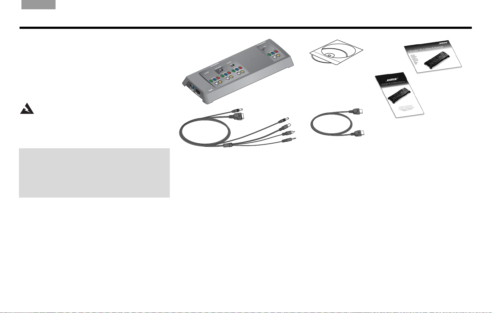
VS-2 video enhancer
VS-2 cable
If you need additional cables
Your VS-2 includes one HDMI video cable, but you may need additional cables to set up the VS-2 with your
LIFESTYLE® system. To determine if you need any additional cables, please read this guide before you begin the
actual setup. You can purchase additional cables from your Bose dealer or local electronics retailer.
Software update disc
HDMI video cable
Owner’s
guide
Quick setup
guide
IMPORTANT
Software update required!
Your VS-2 comes with a software update disc.
Before setting up the VS-2, you must load this CD into
the Lifestyle system media center and allow it to update
your system.
Unpacking
Carefully unpack the VS-2 video enhancer. Check to be sure
your system includes the parts shown on this page. Save all
packing materials in case you need to repack and transport
your product.
If any part of the product appears damaged, do not attempt to
use it. Notify Bose or your authorized Bose® dealer immediately. For Bose contact information, refer to the address sheet
in
cluded in the carton.
WARNING: To avoid danger of suffocation, keep the
plastic bags out of the reach of children.
Updating the system software
1. Turn on your LIFESTYLE® system and select the
CD/DVD source.
2. Load the software update disc into the media center disc
player.
Wait for the display window of the media center to indicate
when it is done.
5
Page 6
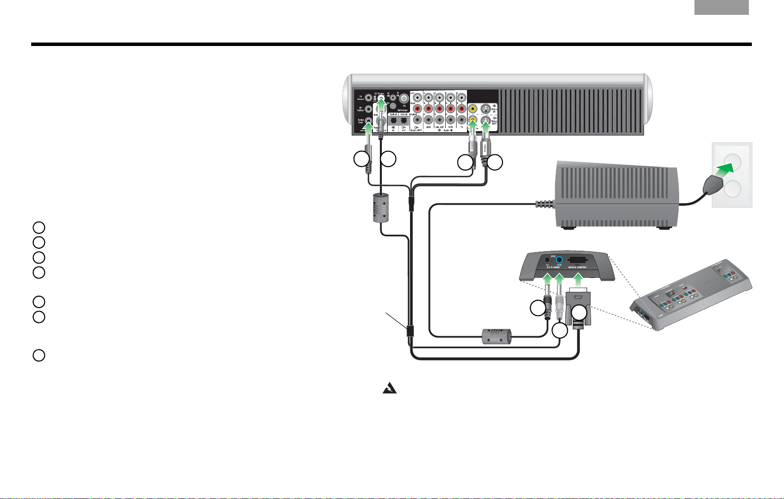
VS-2 cable
VS-2 end panel
Media center power supply
Media center rear panel
WARNING: The VS-2 must be used only with the media center power supply
that came with your LIFESTYLE® DVD home entertainment system.
2
3
4
1
5
6
7
Connecting the VS-2 to Your Media Center
• Connect the 4-connector end of the VS-2 cable to your media center:
1 Insert the Serial Data plug into the Serial Data connector.
2 Insert the DC Power plug into the DC Power connector.
3 Insert the Composite plug into the Composite Video OUT connector.
4 Insert the S-Video plug into the S-Video OUT connector.
• Connect the other end of the VS-2 cable to the VS-2 end panel:
5 Insert multi-pin plug into the Media Center connector.
6 Insert the DC Power plug into the DC POWER Out connector.
• Connect the media center power supply to the end panel of the VS-2:
7 Insert the DC power cable from the media center power supply into the
DC POWER In connector.
Note: Straighten the DC power cord from the media center power supply and
from the VS-2 to the media center as much as possible. This cord is used as
the antenna for your LIFESTYLE
®
system remote control.
Preparation
When setting up a LIFESTYLE® system with the VS-2, the media center
power supply plugs into the VS-2 instead of the media center.
• If
you are setting up the VS-2 and your LIFESTYLE® system at the
same time, find the media center power supply in the LIFESTYLE
system carton before you begin.
• If
you are adding the VS-2 to an existing LIFESTYLE® system, turn
off your LIFESTYLE system, wait 30 seconds, and unplug the media
center power supply from the wall outlet. Then, disconnect the
supply from the rear panel of the media center. Also, remove any video
cables from the Video OUT and Video IN connectors on the media center.
power
English
Connecting the VS-2 to your media center
6
Page 7

English
Composite
Standard quality
S-Video
Good quality
Component
Best quality
Video
Quality
TV Video
Connector Cable Type
Connection
Instructions
Check
One
Best
HDMI
Go to page 8.
Component
Go to page 10.
Good S-Video
Go to page 12.
Standard Composite
Go to page 14.
Supplied with
the VS-2
Not supplied
Supplied
with your
LIFESTYLE®
system
Supplied
with your
LIFESTYLE
®
system
HDMI
Best quality
DVI You may have a TV that has a DVI connector, but not an HDMI
connector. In this case, you still can use an HDMI connection by
using a DVI-to-HDMI cable adapter or a DVI-to-HDMI cable.
Identifying your TV connectors
Your TV may have some or all of the video input connectors
shown on the right. Each type of video connector provides
a different level of video image quality.
Examine the rear panel of your TV and
has HDMI, component, S-Video, or composite video input
connectors. For additional instructions, refer to the owner’s
guide that came with your TV.
determine whether it
Your TV Connection Options
Choosing the TV connector you
will use
1. Using the table on the right, choose the available TV
video connector that provides the highest possible
video quality.
ake sure you have the correct cable on hand. An HDMI
2. M
cable is provided with the VS-2.
3. Go to the page listed for instructions on making the
connections to your TV and other A/V devices.
4. As a reminder, place a check mark in the table to indicate
your choice.
7
Page 8
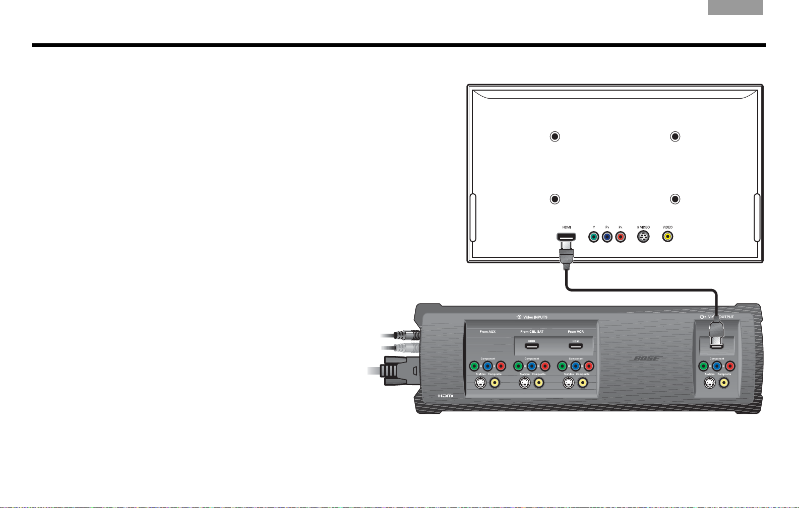
Using an HDMI TV Connection
TV
VS-2
Connecting the VS-2 HDMI output to your TV
To connect your TV to the VS-2 using the supplied HDMI cable, do the following:
ug one end of the HDMI cable into the HDMI connector on the rear of your
1. Pl
TV.
2. Plug the other end of the HDMI cable into the Video OUTPUT HDMI connector
on the VS-2.
3. Go to page 9 for instructions on connecting other A/V devices to the VS-2.
English
8
Page 9

English
VS-2
DO NOT USE
If any of your A/V devices do not have an HDMI connector, you can use any other
type of connection. Remember, the VS-2 converts these up to HDMI format.
Choosing connection types for your A/V devices
1. Look at the rear panel of each A/V device to determine what type of video output connectors it has.
2. In the
following table, choose the type of available video connector that provides the highest possible video
quality. We recommend using either an HDMI or Component connection if they are available. Place a check
mark in the table for the connector type used for each of your A/V devices.
Video
Quality
Best
Good S-Video
Standard Composite
Video
Connector VCR CBL•SAT
HDMI
Component
AUX
(Other)
Not
available
on VS-2
Connecting your A/V devices to the VS-2
1. Plug one end of the video cable into the appropriate video output connector(s) on your A/V device.
2. Plu
3. Re
g the other end of the video cable into the appropriate Video INPUT connector(s) on the VS-2.
fer to your LIFESTYLE® system installation guide for information on making audio connections.
9
Page 10

Using a Component Video TV Connection
TV
VS-2
Connecting the VS-2 component video output to your
TV
You need to obtain a component video cable from Bose or your local electronics dealer to
complete this connection.
To connect your TV to the VS-2 using a component video cable (not supplied), do the
following:
1. Plug one end of the component video cable into the component connectors on the rear
of your TV. Be sure to match the color of each plug to the color of each connector.
2. Plu
3. Go to page 11 for instructions on connecting other A/V devices to the
g the other end of the component video cable into the Video OUTPUT Component
connectors on the VS-2. Again, be sure to match the color of each plug to the color of each
connector.
VS-2.
English
10
Page 11

English
VS-2
If any of your A/V devices do not have component video connectors, you can use
either an S-Video or Composite connection. Remember, the VS-2 converts either
of these up to component video format.
Choosing connection types for your A/V devices
1. Look at the rear panel of each A/V device to determine what type of video output connectors it has.
2. In the
following table, choose the type of available video connector that provides the highest possible video quality. We recommend using a component connection if
the table for the connector type used for each of your A/V devices.
it is available. Place a check mark in
Video
Quality
Best Component
Good S-Video
Standard Composite
Video
Connector VCR CBL•SAT
AUX
(Other)
Connecting your A/V devices to the VS-2
1. Plug one end of the video cable into the appropriate video output connector(s) on your A/V device. If
you are making a component connection, be sure to match the color of the plug to the color of the
connector.
2. Plug the other end of the video ca
if you are making a component connection, be sure to match the color of the plug to the color of the
connector.
3. Re
fer to your LIFESTYLE® system installation guide for information on making audio connections.
ble into the appropriate Video INPUT connector(s) on the VS-2. Again,
11
Page 12

Using an S-Video TV Connection
TV
VS-2
Connecting the VS-2 S-Video output to your
TV
You can use the S-Video cable included with your LIFESTYLE® system to
make this connection.
To connect your TV to the VS-2 using an S-Video cable, do the following:
ug one end of the S-Video cable into the S-Video connector on the rear
1. Pl
of your TV.
2. Plug the other end of the S-Video cable into the Video OUTPUT S-Video
connector on the VS-2.
3. Go to page 13 for instructions on connecting other A/V devices to the
VS-2.
English
12
Page 13

English
DO NOT USE
DO NOT USE
DO NOT USE
VS-2
If any of your A/V devices do not have an S-Video connector, you can use a
Composite connector. Remember, the VS-2 converts this up to S-Video format.
Choosing connection types for your A/V devices
If you connected your TV to the VS-2 using an S-Video cable, you can use only an S-Video or Composite connection for your A/V devices even though a device m
1. Look at th
2. In t
We recommend using an S-Video connection if it is available. Place a check mark in the table for the connector type used for each of your A/V devices.
e rear panel of each A/V device to determine what type of video output connectors it has.
he following table, choose the type of video connector that provides the highest possible video quality.
ay have HDMI or component video output connectors.
Video
Quality
Good
Standard Composite
Video
Connector VCR CBL•SAT
S-Video
AUX
(Other)
Connecting your A/V devices to the VS-2
1. Plug one end of the video cable into the appropriate video output connector on the rear of your A/V
device.
2. Plug the other end of the video cable into the appropriate Video INPUT connector(s) on the VS-2.
3. Re
fer to your LIFESTYLE® system installation guide for information on making audio connections.
13
Page 14

Using a Composite Video TV Connection
TV
VS-2
Connecting the VS-2 composite video output
to your TV
You can use the composite video cable included with your LIFESTYLE® system to
make this connection.
To connect your TV to the VS-2 using a composite video cable, do the following:
ug one end of the composite video cable into the composite video
1. Pl
connector on the rear of your TV.
2. Plug the other end of the composite video cable into the Video OUTPUT
Composite connector on the
3. Go to page 15 for instructions on connecting other A/V devices to the
VS-2.
VS-2.
English
14
Page 15

English
DO NOT USE
DO NOT USE
DO NOT USE
VS-2
Choosing connection types for your A/V devices
If you connected your TV to the VS-2 using a composite video cable, you can use only an S-Video or Composite
connection for your A/V devices even though a device may have HDMI or component video output connectors.
1. Look at the rear panel of each A/V device to determine what type of video output connectors it has.
2. In the
following table, choose the type of video connector that provides the highest possible video quality.
We recommend using an S-Video connection if it is available. Place a check mark in the table for the connector type used for each of your A/V devices.
Video
Qu
ality
Good
Standard Composite
Video
Connector VCR CBL•SAT
S-Video
AUX
(Other)
Connecting your A/V devices to the VS-2
1. Plug one end of the video cable into the appropriate video output connector on the rear of your A/V device.
2. Plu
3. Re
g the other end of the video cable into the appropriate Video INPUT connector on the VS-2.
fer to your LIFESTYLE® system installation guide for information on making audio connections.
15
Page 16

Program Recording Connections
1
2
VCR/DVR video
to the VS-2
Cable/satellite video to the VS-2
VCR/DVR audio to
the media center
Cable/satellite audio
to the media center
VS-2
LIFESTYLE® media center
1
2
Connecting your cable/satellite box to
your VCR/DVR
To record programs from your cable or satellite service, you can connect
your cable/satellite box to your VCR or DVR. The diagram on this page
is an example of how this equipment may be connected.
Before you start, make sure that your
have the necessary input and output connectors available.
Connect an unused video output on your cable/satellite box to an
unused video input on your VCR/DVR. Choose the connection
type tha
page 7.
Connect an unused audio output on your cable/satellite box to an
unused audio input on your VCR/DVR.
t provides the highest level of image quality. Refer to
Recording programs
Using the connection method in the example diagram, you do not need
to select the CBL•SAT source in order to record the program. If you
wish, you can listen to another source while recording.
cable/satellite box and VCR/DVR
English
16
Page 17

English
New System menu items
When the VS-2 is connected to your LIFESTYLE® system, the following new items will appear in the System menu.
Video options
New Item Possible Settings (Factory/default settings in bold type)
Widescreen TV No.....................Tells your LIFESTYLE® system that it is connected to a 4:3 TV.
Yes .................... Tells your LIFESTYLE® system that it is connected to a 16:9 (widescreen) TV.
Video Resolution
(only for HDMI TV
connection)
Persistent Video Disabled..
Settings on TV Yes ..
Audio options
New Item Possible Settings (Factory/default settings in bold type)
CBL•SAT/VCR Audio
(only for HDMI
connections)
Adjustable ......Allows your LIFESTYLE® system to select the optimal video resolution setting for your TV.
Fixed.................Prohibits any change to video resolution.
Enabled.............Allows the video from your selected source (CBL•SA
.................Allows the Settings menu for the TV, CBL•SAT, VCR, and AUX sources to appear on your TV
No .....................Allows the Settings menu for the TV, CBL•SAT, VCR, and AUX sources to appear only on the
Bose 5.1 ..........Allows you to hear 5.1-channel surround sound from your LIFESTYLE® system when the
TV Stereo ..........Tells the VS-2 to send two-channel digital audio received (through an HDMI cable) from your
Refer to Video Resolution in “New Settings menu items” on page 18.
........Removes video from your TV screen when switching from your selected video source to an
audio source.
T, VCR, or AUX) to remain on your TV
screen when switching from this source to an audio source.
screen as well as on the media center display window.
media center display window.
selected source is CBL•SAT or VCR. Recommended setting – should not be changed.
cable/satellite box or VCR to your TV (through an HDMI cable). The LIFESTYLE® system
speakers are silent.
Operating Information
17
Page 18

New Settings menu items
When the VS-2 is connected to your LIFESTYLE® system, the following new items appear in the Settings menu.
New Menu Item Description Possible Settings (Factory/default settings in bold type)
English
Audio Delay Changes the amount of delay between
Video Resolution Lists output video resolutions sup-
Image View Modifies the image on your TV screen. Gray Bars ....Adds a vertical gray bar to
SD Progressive
Scan
and video. Used to synchronize
audio
the audio with the action when viewing
audio/video program content.
ported by your TV when it is connected
to the HDMI out
optimal resolution for your TV is listed
as the default setting and remains
selected unless you change it.
Available only when the Video Resolution option in the System menu is set
to Adjustable.
For standard-definition video,
determines whether in
progressive video is sent to your TV.
Available only when your TV is
connected to the VS-2 using a
component video cable.
put of the VS-2. The
terlaced or
0 (no delay), 1, 2, 3, 4, 5, 6, 7, 8 (maximum delay)
480/576p (lowest quality), 720p, 1080i, 1080p (highest quality)
Stretch ........Stretches the image horizontally to fit the screen.
Zoom ..........Image size is increased horizont
Normal .......Image is not changed.
Off ...............Sends interlaced video (480i or 576i) to your TV.
On...............Sends progressive video (480p or 576p) to your TV.
the left and right side of the image.
ally and vertically to fit the screen.
18
Page 19

English
TV
CHOOSE TV INPUT
navigate
select
Choose the device that you have connected to the TV Audio IN jacks.
AUX Device:
AUX Brand:
AUX Code:
TV Control:
Remote Version
IR Control:
AUX
VCR
CBL•SAT
TV
Remote Control
Media center display – blank TV message
System menu – Remote Control options
Switching sources
Adding the VS-2 to your system setup greatly simplifies source selection. Just press the remote
button (CD/DVD, VCR, CBL•SAT, or AUX) for the source you want to use. If you select one of the
sources connected to the VS-2, be sure the source is turned on.
Selecting TV channels
When the VS-2 is connected to your LIFESTYLE® system, the remote changes channels on the
source selected by the TV Control setting (CBL•SAT, VCR, TV, or AUX) in the System menu under
Remote Control options. This means that when you select the TV source on the remote, you see
and hear the TV channel coming from your TV Control selection. For example, if you set TV
control to CBL•SA
program on the selected channel of your cable or satellite box.
If TV Contr
source unless you enable the Persistent Video option (see “New System menu items” on page 17).
If your TV screen is blank, the media center display
the correct video input on your TV.
ol is set to TV (default setting), your TV screen goes blank when selecting the TV
Watching video from one source while listening to audio from
another
Normally, when you switch to an audio source from a video source, your TV screen goes blank. To
change this so the video source remains on your TV screen, go to the System menu and change
the Persistent Video option setting to Enabled.
Enabling Persistent Video allows you to continue viewi
listening to the audio from another sour
ball game on your TV while listening to the broadcast audio of the same ball game from a local
radio station.
T and press the TV source button on your remote, you will see and hear the
s CHOOSE TV INPUT to remind you to select
ce, such as FM or AM radio. For example, you can watch a
ng the video portion of a program while
19
Page 20

Mounting Your VS-2 on a Wall
Install two screws 12 inches apart.
Leave ¼ inch (6 mm) between wall
surface and screw head.
Position the VS-2 mounting holes over the
screws so that it is flush with the wall.
Lower the VS-2 onto the screws
to lock it in place.
1
2
3
For solid wood
For wallboard
-inch (3.5 mm) drill bit
1
8
Use drill size
specified for type
of wall anchor
used.
No. 8 x 1½-inch
(M4 x 36 mm)
wood screws
No. 8 x 1½-inch (M4 x 36 mm)
wood or machine screws (depends
on type of wall anchor)
No. 8 (M4)
wall anchor
Required tools
Recommended hardware
English
20
Page 21

English
Cleaning
• Use only a soft, dry cloth to clean the outside of the VS-2.
• Do not use any solvents, chemicals, or cleaning solutions containing alcohol, ammonia, or abrasives.
• Do not allow liquids to spill into any openings.
• Do not use any sprays near the VS-2.
Troubleshooting
Problem What to do
Maintaining Your VS-2
System will not turn on • Make sure the VS-2 cable is correctly connected between the VS-2 and the media center (see “Connecting the VS-2 to your media
No picture on TV • If you have not done so, load the software update disc into the DVD player. See “Updating the system software” on page 5.
The wrong picture appears
TV for the source I
on my
selected
Some sources do not
pear on my TV
ap
center” on page 6).
• Make sure the media center power supply i
• Make sure the VS-2 cable is correctly connected between the VS-2 and the media center (see “Connecting the VS-2 to your media
center” on page 6).
• Make sure you connected your TV to the TV ou
• Make sure you have selected the corr
• If you have not done so, load the software update disc into the DVD player. See “Updating the system software” on page 5.
• Make sure your sources are connected to the appropriate VS-2 inputs.
• Make sure the Serial Data plug from the VS-2 is fully inserted into the media center connector.
• Make sure you have selected the corr
• Make sure your sources are connected to the appropriate VS-2 inputs.
• Make sure you have not used a source that outputs a video format that is higher in quality than what your TV can accept.
s plugged into an AC receptacle.
tput connector on the VS-2.
ect video input on your TV.
ect video input on your TV.
21
Page 22

English
Technical information
Dimensions
15.6" W x 4.8" D x 1.6" H
(39.55 cm x 12.07 cm x 4.0 cm)
VS-2 power rating
9 W
Video inputs
(2) HDMI (CBL•SAT and VCR)
(3) Component
(3) S-Video
(3) Composite
Video output
HDMI
Component
S-Video
Composite
Weight (approximate)
2.5 lb (1.13 kg)
Finish
Diecast aluminum
Copyright and license protections
©2008
Bose Corporation. No part of this work may be reproduced, modified, distributed,
or otherwise used without prior written permission. All trademarks referenced herein are
property of Bose Corporation.
HDMI, the HDMI logo and High-Definition Multimedia Interface are trademarks or
registered trademarks of HDMI Licensing LLC.
This product incorporates copyright protection technology that is protected by method
claims of certain U.S. patents and other intellectual property rights owned by
Macrovision Corporation and other rights owners. Use of this copyright protection
technology must be authorized by Macrovision Corporation, and is intended for home
and other limited viewing uses only unless otherwise authorized by Macrovision
Corporation. Reverse engineering or disassembly is prohibited.
The SimplayTM logo and the ‘SimplayTM,’ and ‘Simplay LabsTM,’ trademarks are owned by
Silicon Images, Inc. and are used under license from Silicon Images, Inc. and/or Simplay
Labs, LLC.
Contacting Customer Service
If you need help solving problems while setting up this product, contact Bose® Customer
Service. See the address and phone number list included with your system.
22
Page 23

English
Limited Warranty
What is covered:
All parts defective in material and workmanship. This limited warranty for the LIFESTYLE® VS-2 video
enhancer covers the functionality of the system for its normal, intended use as specified in the
Owner’s Guide and does not cover a malfunction that has resulted from improper or unreasonable use
or maintenance, accident, excess moisture, improper packing, lightning, power surges, or unauthorized tampering, alteration or modification while not under the control of Bose. Bose
designed to be used in every environment, so please review your Owner’s Guide.
WHERE PERMITTED, THE PROVISIONS OF THIS LIMITED WARRANTY ARE IN LIEU OF ANY OTHER
WARRANTY, WHETHER EXPRESS OR IMPLIED, WRITTEN OR ORAL, INCLUDING ANY WARRANTY
OF MERCHANTABILITY OR FITNESS FOR A PARTICULAR PURPOSE.
For how long:
In countries where the duration of a warranty is not determined by statute, the Bose Limited Warranty
lasts one year from the purchase date. For countries where minimum warranty terms are determined
by statute, the Bose Limited Warranty term is the longer of the statutory period or the term listed
above.
Notwithstanding the above, in the United States, where applicable, if you qualify as a “consumer”
under the Magnuson-Moss Warranty Act, then you may be entitled to any implied warranties allowed
by law for the period of the express Limited Warranty as set forth below. Some states do not allow limitations on how long an implied Limited Warranty lasts, so the above limitation may not apply to you.
What we will do:
At our option, we will repair or replace any defective parts within a reasonable period of time and free
of charge.
How you can obtain limited warranty service:
1. You can ship the system to either a Bose Service Agency or to Bose directly with a proof of
purchase from an authorized dealer. Please:
A. Properly and carefully pack the product for shipping. If you need a carton for shipping,
contact Bose for a new carton
B. Please contact Bose to get a return reference number. Place this number prominently on
the outside of the carton.
C. Label and ship the product to the appropriate Bose location.
2. You can return the system with proof of purchase from an authorized dealer to a Bose Service
Agency or directly to Bose. Proof of purchase is not required where it is excluded by statute.
®
systems are not
Other Rights:
EXCLUSIVE REMEDY:
THIS LIMITED WARRANTY IS FULLY TRANSFERABLE PROVIDED THAT THE CURRENT OWNER
FURNISHES THE ORIGINAL PROOF OF PURCHASE FROM AN AUTHORIZED BOSE DEALER. THE
MAXIMUM LIABILITY OF BOSE SHALL NOT EXCEED THE ACTUAL PURCHASE PRICE PAID BY
YOU FOR THE PRODUCT. IN NO EVENT SHALL BOSE BE LIABLE FOR SPECIAL, INCIDENTAL,
CONSEQUENTIAL OR INDIRECT DAMAGES. SOME PLACES DO NOT ALLOW LIMITATIONS OR THE
EXCLUSION OR LIMITATION OF RELIEF, SPECIAL, INCIDENTAL, CONSEQUENTIAL OR INDIRECT
DAMAGES TO SPECIFIED AMOUNTS, SO THE ABOVE LIMITATIONS OR EXCLUSIONS MAY NOT
APPLY TO YOU.
OTHER CONDITIONS:
FOR YOUR BENEFIT, WE RECOMMEND THAT YOU RECORD YOUR SERIAL NUMBERS(S), FOUND
ON THE PRODUCT(S), AND OTHER PURCHASE INFORMATION, AND KEEP IT WITH YOUR PERSONAL RECORDS ALONG WITH PROOF OF PURCHASE. IF NECESSARY, THIS INFORMATION
WILL ALLOW US TO BETTER SERVE YOUR NEEDS.
THIS LIMITED WARRANTY GIVES YOU SPECIFIC RIGHTS SUBJECT TO SPECIFIED CONDITIONS.
YOU MAY ALSO HAVE OTHER LEGAL RIGHTS WHICH APPLY TO THE PRODUCT YOU HAVE
ACQUIRED. THESE LEGAL RIGHTS VARY FROM STATE TO STATE OR COUNTRY TO COUNTRY.
SOME PLACES DO NOT ALLOW THE EXCLUSION, RESTRICTION OR MODIFICATION OF CERTAIN
IMPLIED RIGHTS OR THEIR EFFECT. IN THOSE SITUATIONS THIS LIMITED WARRANTY WILL ONLY
APPLY TO THE EXTENT THAT THE APPLICABLE LAW ALLOWS. OTHER LAWS PROVIDE YOU WITH
A STATUTORY CLAIM AGAINST THE SELLER.
The laws of your state or country may provide you with legal claims against the seller or manufacturer
of this product. The Limited Warranty does not affect those rights.
Remedies:
The provisions of this Limited Warranty are in lieu of any other warranties or conditions, except those
provided by law. This Limited Warranty does not affect any legal rights provided to you by law and
does not preclude any legal remedy you may have under the law.
This Limited Warranty is void if the label bearing the serial number has been removed or defaced.
23
Page 24

©2008 Bose Corporation, The Mountain,
Framingham, MA 01701-9168 USA
AM301726 Rev.01
 Loading...