

Page 1
L1® model 1S system
with ToneMatch® port
Owner’s Guide
Brugervejledning
Bedienungsanleitung
Guía de usuario
Notice d’utilisation
Manuale di istruzioni
Gebruiksaanwijzing
Bruksanvisningen
Page 2
SAFETY INFORMATION
Please complete for your records
Now is a good time to record the serial numbers of your system here and on your product registration card. You
can register your product online at www.Bose.com/register or call (800) 905-1044. Failure to do so will not
affect your warranty rights.
L1
®
model 1S power stand: _____________________________________________________________________
Top array and bottom extension: _________________________________________________________________
B1 or B2 bass module: _________________________________________________________________________
Please read this owner’s guide
Please take the time to follow the instructions in this owner’s guide carefully. It will help you set up and operate your
system properly and enjoy its advanced features. Please save this owner’s guide for future reference.
WARNING:
To reduce the risk of fire or electrical shock, do not expose the system to rain or moisture.
EnglishDeutschFrançais DanskEspañolItalianoSvenska Nederlands ItalianoSvenska DeutschNederlands Français Español
WARNING:
Refer servicing to qualified service personnel.
CAUTION:
CAUTION:
regulatory compliance, and system performance.
CAUTION:
CAUTION:
remain readily operable.
To reduce the risk of electric shock, do not disassemble this system unless you are qualified.
The lightning flash with arrowhead symbol within an equilateral triangle alerts the user to the presence
of uninsulated, dangerous voltage within the system enclosure
constitute a risk of electrical shock.
The exclamation point within an equilateral triangle, as marked on the system, is intended to alert the user
to
the presence of important operating and maintenance instructions in this owner’s guide.
This product shall be connected to a mains socket outlet with a protective earthing connection.
Make no modifications to the system or accessories. Unauthorized alterations may compromise safety,
Do not place any naked flame sources, such as lighted candles, on or near the apparatus.
Where the mains plug or appliance coupler is used as the disconnect device, such disconnect device shall
that may be of sufficient magnitude to
Note: The product must be used indoors. It is neither designed nor tested for use outdoors, in recreation vehicles, or on
boats.
This product conforms to all applicable EU re
www.Bose.com/compliance.
©2012 Bose Corporation. No part of this work may be reproduced, modified, distributed, or otherwise used without prior written
permission.
2
quirements.The complete Declaration of Conformity can be found at:
Page 3

English Deutsch FrançaisDansk Español Italiano SvenskaNederlandsItaliano SvenskaDeutsch NederlandsFrançaisEspañol
Information about products that
generate electrical noise
NOTE: This equipment has been tested and found to
comply with the limits for a Class A digital device,
pursuant to part 15 of the FCC Rules.These limits are
designed to provide reasonable protection against
harmful interference when the equipment is operated in
a commercial environment. This equipment generates,
uses, and can radiate radio frequency energy and, if
not installed and used in accordance with the
instruction manual, may cause harmful interference to
radio communications. Operation of this equipment in
a residential area is likely to cause harmful interference
in which case the user will be required to correct the
interference at their own expense.
Changes or modifications not expressly approved by
Bose Corporation could void the user's authority to
operate this equipment.
This Class A digital apparatus complies with Canadian
ICES-003.
Initial turn on inrush current: 32 Amps
Inrush current after AC mains interruption of 5 seconds:
32 Amps
This product meets all EN55103-2 immunity
requirements for E2 electromagnetic environment.
IMPORTANT SAFETY INSTRUCTIONS
1. Read these instructions.
2. Keep these instructions.
3. Heed all warnings.
4. Follow all instructions.
5. Do not use this apparatus near water.
6. Clean only with a dry cloth.
7. Do not block any ventilation openings. Install in
ac
cordanc
tions.
8. Do not install near any heat sources, such as
radiat
ratus (including amplifiers) that produce heat.
9. Do not defeat the safety purpose of the polarized or grounding-type plug. A polarized plug
has two blades with one wider tha
grounding-type plug has two blades and a third
grounding prong. The wider blade or third prong
is provided for your safety. If the provided plug
does not fit into your outlet, consult an electrician for replacement of the obsolete outlet.
10. Protect the power cord from being walked on or
pinche
receptacles, and the point where they exit from
the apparatus.
11. Only use attachments/accessories specified by
the manufacture
12. Use only with the cart, stand, tripod,
bracket, or table specified by the manufacturer or sold with the apparatus.
When a cart is used,
moving the cart/apparatus combination to avoid
injury from tip-over.
13. Unplug this apparatus during lightning storms
or when unused for
e with the manufacturer’s instruc-
ors, heat registers, stoves, or other appa-
n the other. A
d, pa
rticularly at plugs, convenience
r.
use caution when
long periods of time.
14.
Refer all servicing to qualified service personnel.
Servicing is required when the apparatus has
been damaged in any way, such as power-supply
cord or plug is damaged, liquid has been spilled
or objects have fallen into the apparatus, the
apparatus has been exposed to rain or moisture,
does not operate normally, or has been dropped.
15. To prevent risk of fire or electric shock, avoid
ets, extension cords, or
overloading wall
integral convenience receptacles.
16. Do not let objects or liquids enter the product –
as th
ey may touch dangerous voltage points or short-
circuit parts that could result in a fire or electric shock.
17. See product enclosure bottom for safety-related
markings.
18. Use proper power sources – Plug th
a proper power source, as described in the operating
instructions or as marked on the product.
19. Apparatus shall not be exposed to dripping or
splashing, and no o
such as vases, shall be placed on the apparatus.
outl
e product into
bjects filled with liquids,
Venice_SafetyInstructions.fm 4/12
3
Page 4

EnglishDeutschFrançais DanskEspañolItalianoSvenska Nederlands ItalianoSvenska DeutschNederlands Français Español
INTRODUCTION 5
Welcome . . . . . . . . . . . . . . . . . . . . . . . . . . . . . . . . . . . . . . . . . . . . . . . . . . . . . . . . . . . . . . . . . . . . . . . . . . . . . . . . . . . 5
Features and benefits . . . . . . . . . . . . . . . . . . . . . . . . . . . . . . . . . . . . . . . . . . . . . . . . . . . . . . .
Product overview . . . . . . . . . . . . . . . . . . . . . . . . . . . . . . . . . . . . . . . . . . . . . . . . . . . . . . . . . . . . . . . . . . . . . . . . . . . . . 6
Connections and controls . . . . . . . . . . . . . . . . . . . . . . . . . . . . . . . . . . . . . . . . . . . . . . . . . . . . . .
. . . . . . . . . . . . . . . . . . 5
. . . . . . . . . . . . . . . . 7
SYSTEM SETUP 9
Parts list . . . . . . . . . . . . . . . . . . . . . . . . . . . . . . . . . . . . . . . . . . . . . . . . . . . . . . . . . . . . . . . . . . . . . . . . . . . . . . . . . . . . 9
Positioning your system . . . . . . . . . . . . . . . . . . . . . . . . . . . . . . . . . . . . . . . . . . . . . . . . . . . . . .
Setting up the power stand . . . . . . . . . . . . . . . . . . . . . . . . . . . . . . . . . . . . . . . . . . . . . . . . . . . . . . . . . . . . . . . . . . . . . 11
Assembling the L1
Connecting to AC power . . . . . . . . . . . . . . . . . . . . . . . . . . . . . . . . . . . . . . . . . . . . . . . . . . . . . . .
Connecting the B1 or B2 bass module . . . . . . . . . . . . . . . . . . . . . . . . . . . . . . . . . . . . . . . . . . . . . . . . . . . . . . . . . . . . 13
Adding a T1 ToneMatch
Adding a second B1 bass module (optional) . . . . . . . . . . . . . . . . . . . . . . . . . . . . . . . . . . . . . . . . . . . . .
®
model 1S system . . . . . . . . . . . . . . . . . . . . . . . . . . . . . . . . . . . . . . . . . . . . . . . . . . . . . . . . . . . . . 11
®
audio engine (optional) . . . . . . . . . . . . . . . . . . . . . . . . . . . . . . . . . . . . . . . . . . . . . . . . . . . . 14
. . . . . . . . . . . . . . . . . . 10
. . . . . . . . . . . . . . . . 12
. . . . . . . . . . . 15
OPERATING INFORMATION 17
Setting the analog input level . . . . . . . . . . . . . . . . . . . . . . . . . . . . . . . . . . . . . . . . . . . . . . . . . . . . . . . . . . . . . . . . . . . . 17
Using a T1 ToneMatch® audio engine and an analog input source . . . . . . . . . . . . . . . . . . . . . . . . . . . . . . . . . . . . . . . 17
User scenarios . . . . . . . . . . . . . . . . . . . . . . . . . . . . . . . . . . . . . . . . . . . . . . . . . . . . . . . . . .
Single musician . . . . . . . . . . . . . . . . . . . . . . . . . . . . . . . . . . . . . . . . . . . . . . . . . . . . . . . . . . .
Multiple musicians . . . . . . . . . . . . . . . . . . . . . . . . . . . . . . . . . . . . . . . . . . . . . . . . . . . . . . . . .
Full band . . . . . . . . . . . . . . . . . . . . . . . . . . . . . . . . . . . . . . . . . . . . . . . . . . . . . . . . . . . . .
DJ events . . . . . . . . . . . . . . . . . . . . . . . . . . . . . . . . . . . . . . . . . . . . . . . . . . . . . . . . . . . .
. . . . . . . . . . . . . . . . . . . . . 17
. . . . . . . . . . . . . . 17
. . . . . . . . . . . . . . 18
. . . . . . . . . . . . . . . . . . 19
. . . . . . . . . . . . . . . . . . 20
CARE AND MAINTENANCE 21
Caring for your product . . . . . . . . . . . . . . . . . . . . . . . . . . . . . . . . . . . . . . . . . . . . . . . . . . . . . . . . . . . . . . . . . . . . . . . . 21
Cleaning . . . . . . . . . . . . . . . . . . . . . . . . . . . . . . . . . . . . . . . . . . . . . . . . . . . . . . . . . . . . .
Getting service . . . . . . . . . . . . . . . . . . . . . . . . . . . . . . . . . . . . . . . . . . . . . . . . . . . . . . . . . .
Troubleshooting . . . . . . . . . . . . . . . . . . . . . . . . . . . . . . . . . . . . . . . . . . . . . . . . . . . . . . . . . . .
Limited Warranty and Registration . . . . . . . . . . . . . . . . . . . . . . . . . . . . . . . . . . . . . . . . . . . . . . . . . . . . . . . . . . . . . . . . 23
Accessories . . . . . . . . . . . . . . . . . . . . . . . . . . . . . . . . . . . . . . . . . . . . . . . . . . . . . . . . . . . .
Technical Information . . . . . . . . . . . . . . . . . . . . . . . . . . . . . . . . . . . . . . . . . . . . . . . . . . . . . . .
Mechanical . . . . . . . . . . . . . . . . . . . . . . . . . . . . . . . . . . . . . . . . . . . . . . . . . . . . . . . . . . . . . . . . . . . . . . . . . . . . . 23
Electrical . . . . . . . . . . . . . . . . . . . . . . . . . . . . . . . . . . . . . . . . . . . . . . . . . . . . . . . . . . . . .
Audio Input/Output . . . . . . . . . . . . . . . . . . . . . . . . . . . . . . . . . . . . . . . . . . . . . . . . . . . . . . . . .
. . . . . . . . . . . . . . . . . . 21
. . . . . . . . . . . . . . . . 21
. . . . . . . . . . . . . . . . . . . 21
. . . . . . . . . . . . . . . . . . . . . 23
. . . . . . . . . . . . . . . . . . . 23
. . . . . . . . . . . . . . . . . . 23
. . . . . . . . . . . . . . 23
4
Page 5

English Deutsch FrançaisDansk Español Italiano SvenskaNederlandsItaliano SvenskaDeutsch NederlandsFrançaisEspañol
INTRODUCTION
Welcome
Thank you for purchasing the Bose® L1® model 1S system with ToneMatch® port. Based on a
revolutionary new technology, this system brings the benefits of an intimate acoustic concert
to amplified performa
nce.
This owner’s guide provides detailed setup and operating instructions for your L1 system a
explains how to connect equipment to it.
For additional information on using this system,
asked questions, please visit www.Bose.com/livesound on the Internet.
Features and benefits
• You control the sound – Just as in an unamplified performance, you control the sound.
You will no longer wonder how you sound to your fellow musicians or to your audience
because you will hear what they hear.
• Q
uick and easy setup –
hours. This frees you from the time-consuming and often frustrating effort required to properly set up conventional sound equipment.
• Dramatically impr
performance and enjoyment dramatically improve because the struggle to hear yourself
and the other musicians is diminished.
• Cr
kin
• You hear what the audience hears – For
audiences hear and thus, are less likely to play at uncomfortable sound levels.
• The music is nat
heard and enjoyed.
• Improves your appearance – T
nd
including tips, techniques, and frequently
The L1 system is easy to carry and can be set up in minutes, not
oved perfo
eates excitement and emotion – Enhanced performance of the musicians creates the
d of excitement and emotion that is valued by music lovers.
urally dynamic – The softest to the most intense passages can be
rmance – Compared to using conventional equipment,
the first time, musicians hear what their
here is less equipment on the stage and more room.
• Sound reproduction unlike before –
excitement that come from hearing the accurate reproduction of sound from each
instrument, and from hearing the sound of each instrument in its position on stage
(as opposed to mono or even stereo mix of all instruments), is unlike anything they have
he
ar
d before in an amplified performance.
Audience members report that the clarity and
Venice_Intro.fm 4/12
5
Page 6
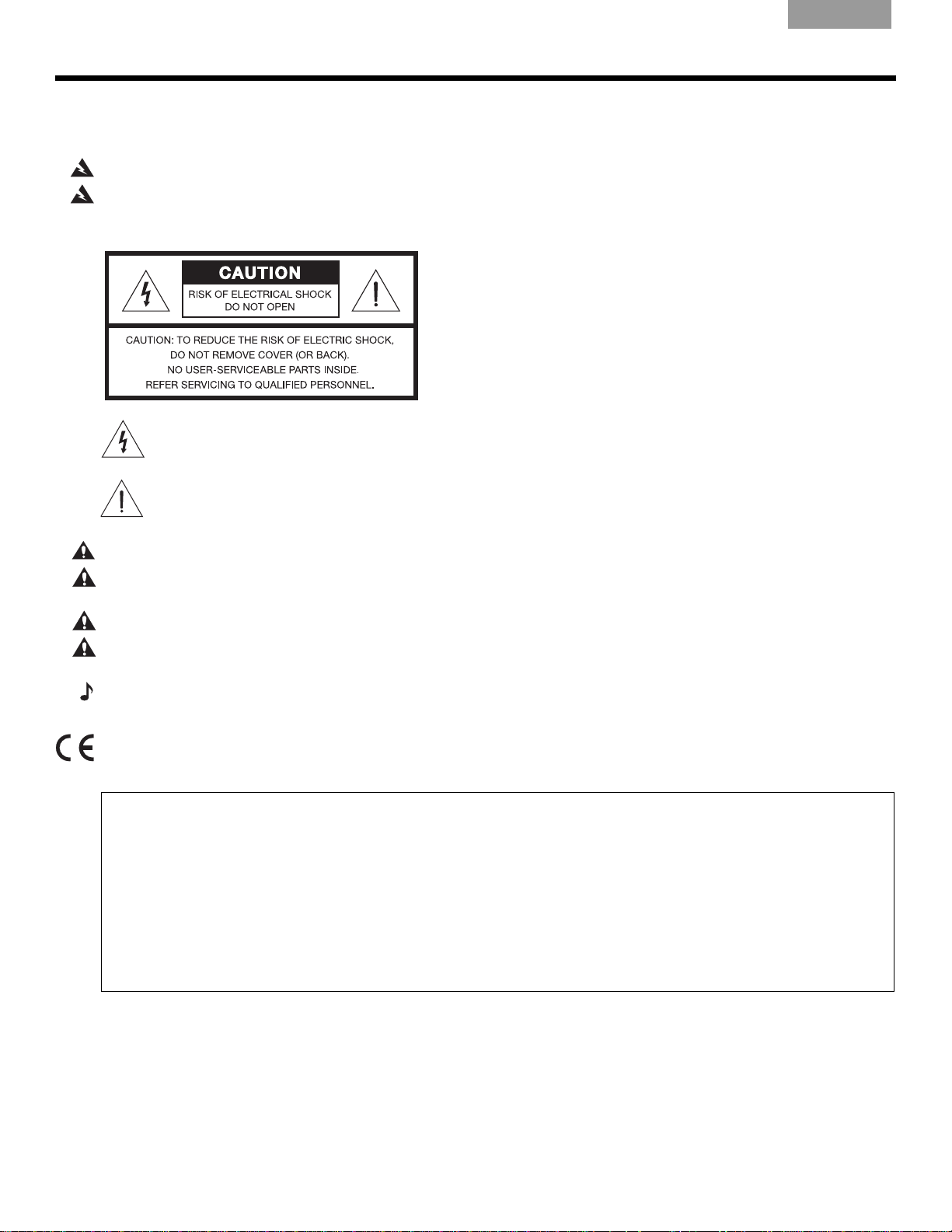
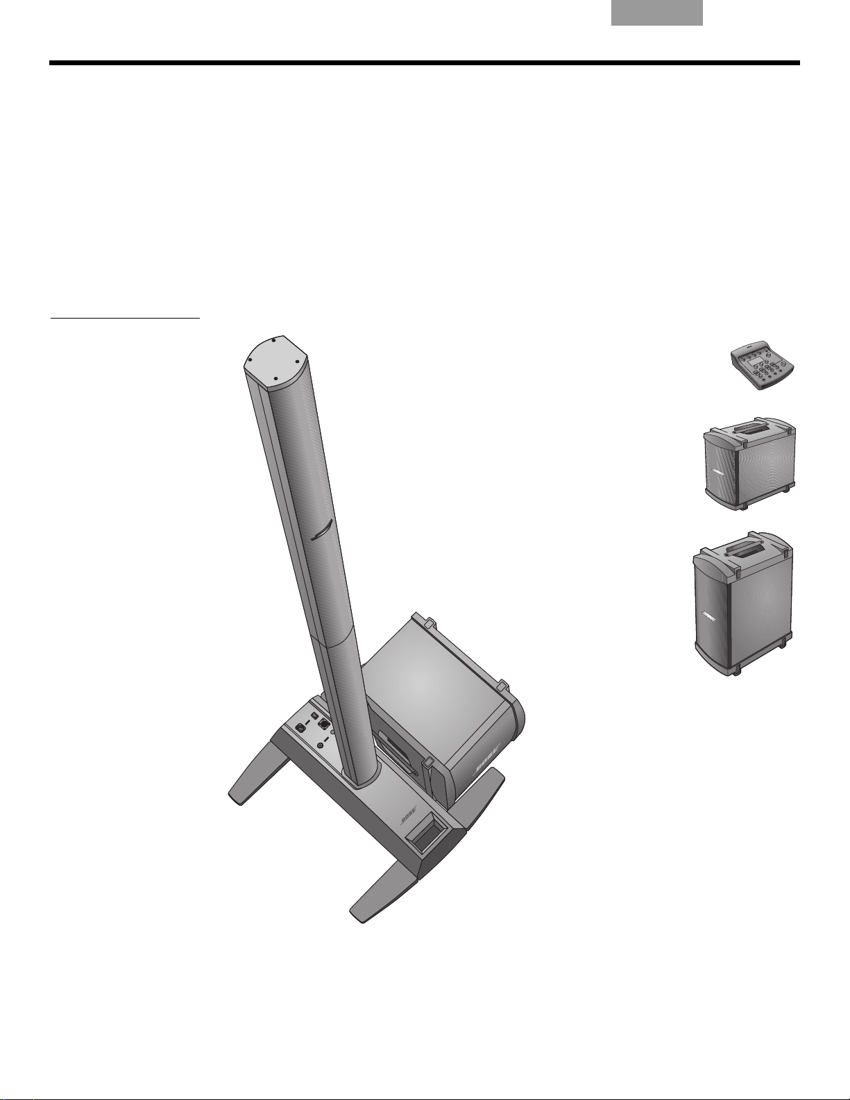
I
Top array
Power stand
L1 model 1S system with ToneMatch port and B1 bass module
Optional equipment
B1 bass
module
T1 ToneMatch
audio engine
Additional
B1 bass
module
B2 bass
module
Bottom
extension
NTRODUCTION
Product overview
Figure 1
L1 model 1S system and
optional equipment
EnglishDeutschFrançais DanskEspañolItalianoSvenska Nederlands ItalianoSvenska DeutschNederlands Français Español
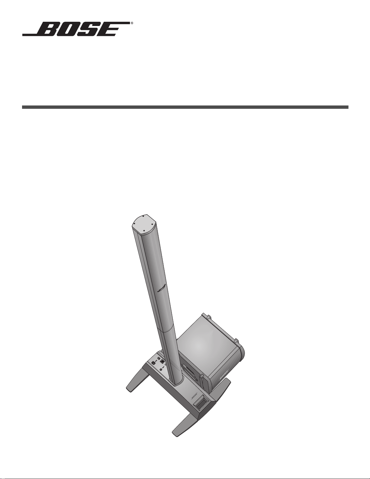
The L1® model 1S system – with ToneMatch® port consists of: the power stand, bottom
extension, top array, and a B1 or B2 bass module. The system
also comes with a padded
carrying bag for each of its parts.
To expand your system and enhance performance, you can add:
• A second B1 bass module for bass guitar, kick drum, or organ. Each power stand can
pow
er up to two B1 bass modules.
• A T1 ToneMatch audio engine for digital signal processing, additional inputs and user-interface control.
For a complete list of optional equipment and accessories, please visit:
www.Bose.com/livesound.
6
Venice_Intro.fm 4/12
Page 7
English Deutsch FrançaisDansk Español Italiano SvenskaNederlandsItaliano SvenskaDeutsch NederlandsFrançaisEspañol
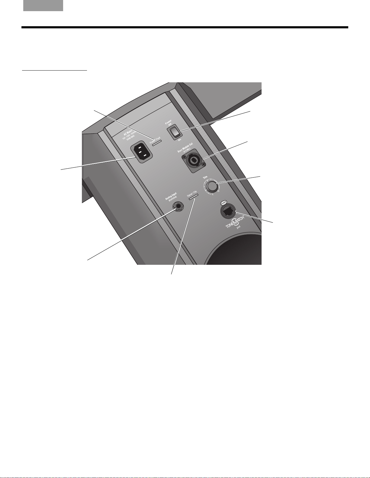
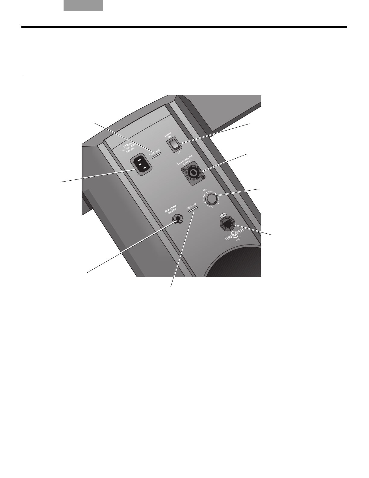
Power switch
Switches the system
on and off.
AC Mains
AC power input
connector.
Bass Module Out
Bass output signal for driving one
or two B1 bass modules. Accepts
a 4-wire bass module cable.
Trim
Adjusts the level of the
analog input signal.
Ton eM atc h
®
port
Digital audio and power connection for the optional T1
ToneMatch audio engine.
Accepts the included
ToneMatch cable.
Analog Input
A line-level analog input. Accepts
a ¼" TRS phone cable. Used for
an instrument or other audio
source.
Signal/Clip LED
Indicates status of the analog input signal.
Green = normal input
Yellow = input approaching clipping
Red = input clipping
Power/Fault LED
Indicates power status.
Blue = system on
Red = system fault
Connections and controls
The top panel of the power stand provides system connectors and controls (Figure 2).
Figure 2
Power stand top panel
I
NTRODUCTION
Venice_Intro.fm 4/12
7
Page 8
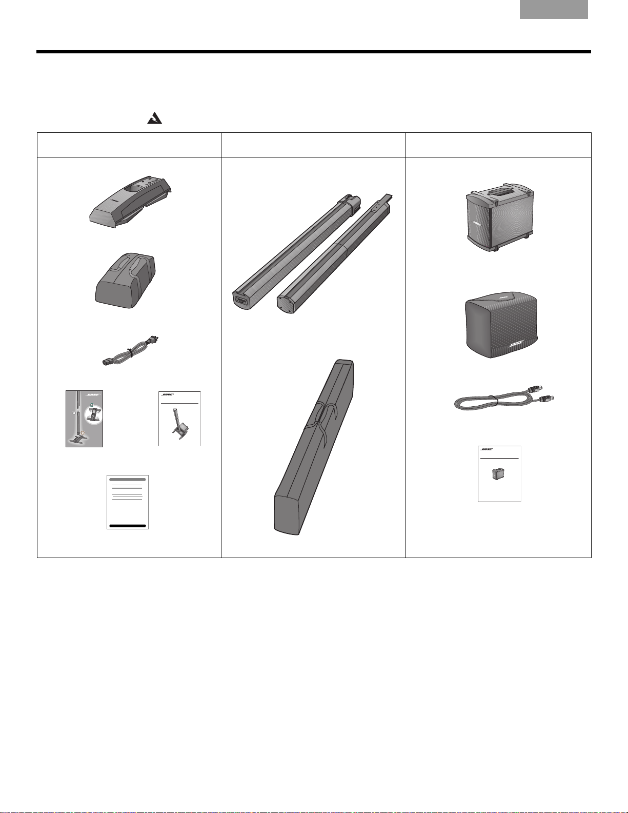
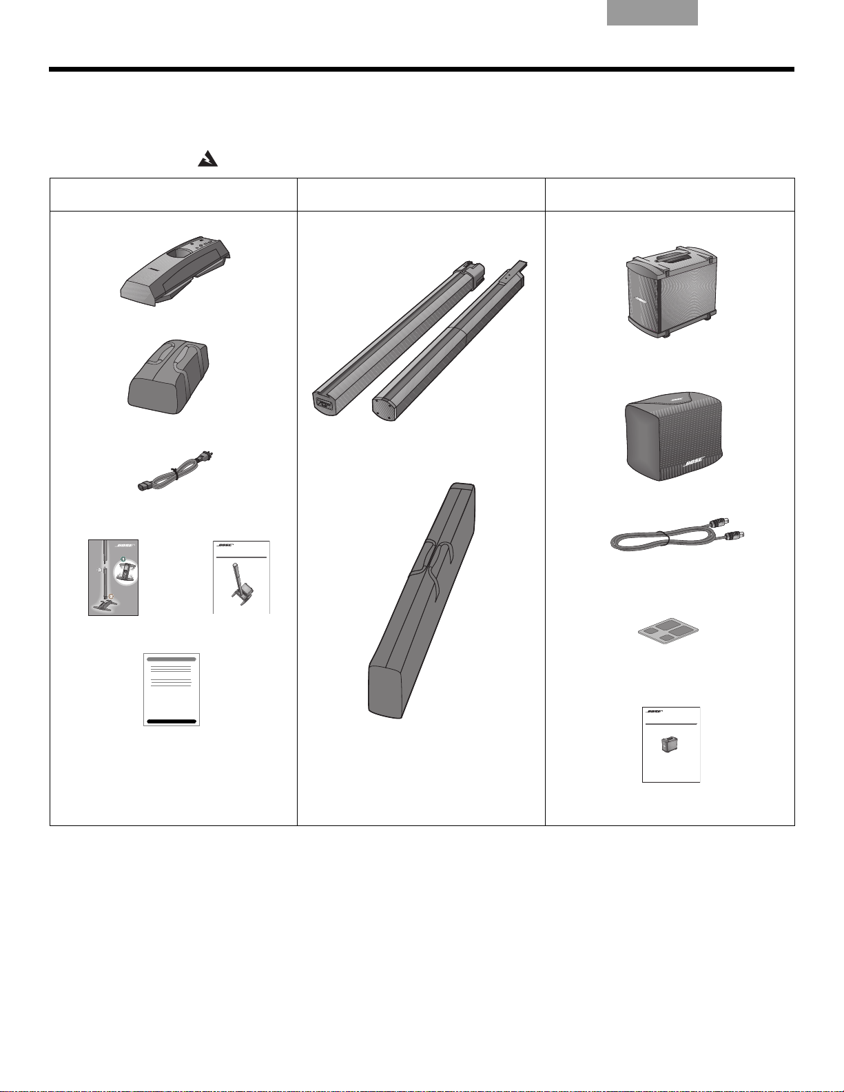
Parts list
L1TM Model II System
with ToneMatchTM port
Owner’s Guide
www.Bose.com/musicians
Top
Bottom
B1
Bass Module
Installation Guide
Power stand carton Array and extension carton B1 or B2 bass module carton
EnglishDeutschFrançais DanskEspañolItalianoSvenska Nederlands ItalianoSvenska DeutschNederlands Français Español
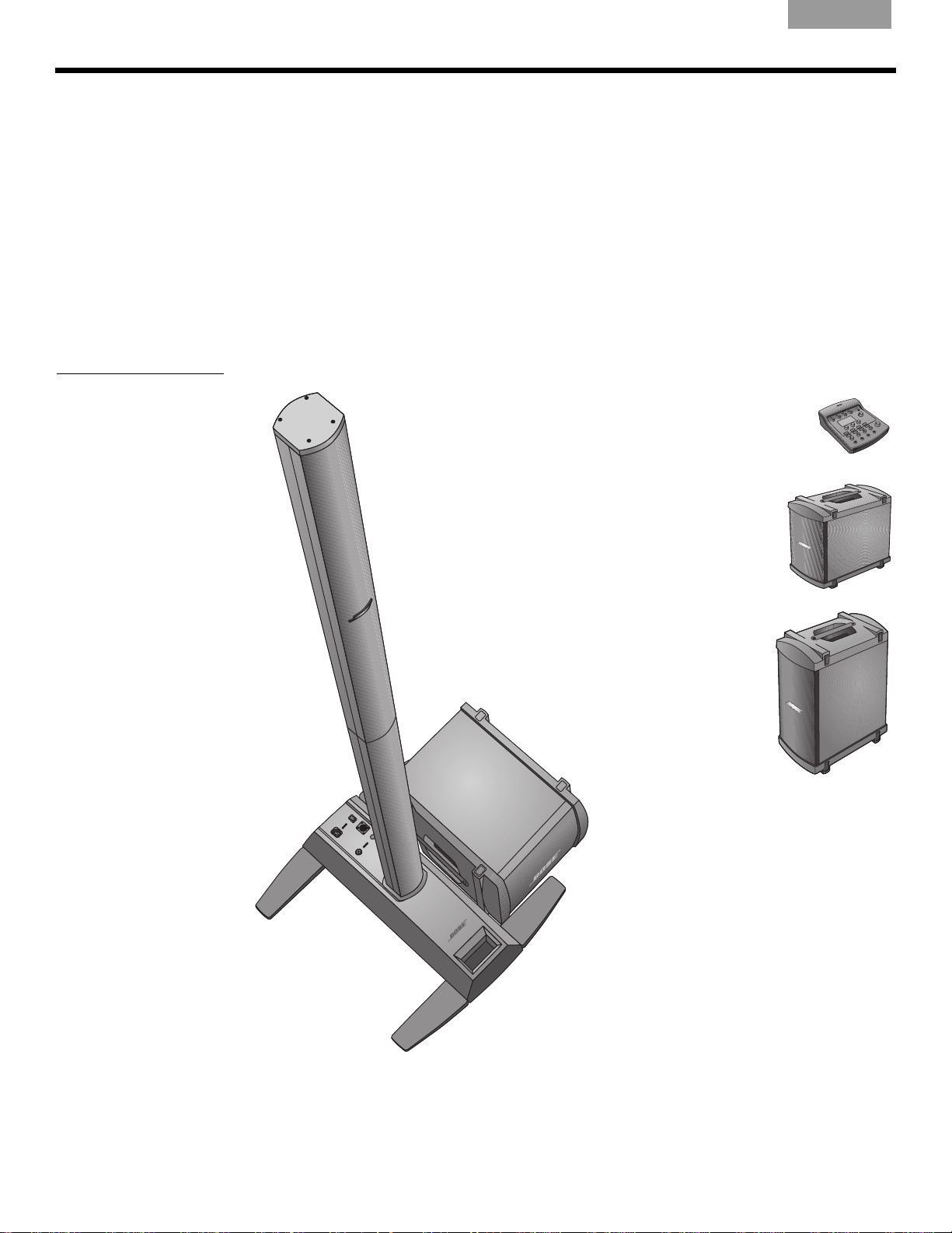
SYSTEM SETUP
The L1® system is shipped in three cartons. Carefully unpack the cartons and check that you
have all the items listed on this page.
WARNING:
To avoid danger of suffocation, keep the plastic bags out of the reach of children.
L1 power stand
Carrying bag
AC power cord
Quick setup guide Owner’s guide
L1 model 1S
top array and bottom extension
Carrying bag
B1 or B2 bass module
Cover
Bass module cable (4-wire)
B1 or B2 bass module owner’s guide
Product registration card
8
Page 9
English Deutsch FrançaisDansk Español Italiano SvenskaNederlandsItaliano SvenskaDeutsch NederlandsFrançaisEspañol
Good
Better
Best
3 ft
(0.9 m)
5 ft
(1.5 m)
7-8 ft
(2.1-2.4 m)
3 ft
(0.9 m)
3 ft
(0.9 m)
3 ft
(0.9 m)
3 ft
(0.9 m)
5 ft
(1.5 m)
5 ft
(1.5 m)
5 ft
(1.5 m)
5 ft
(1.5 m)
7-8 ft
(2.1-2.4 m)
7-8 ft
(2.1-2.4 m)
7-8 ft
(2.1-2.4 m)
7-8 ft
(2.1-2.4 m)
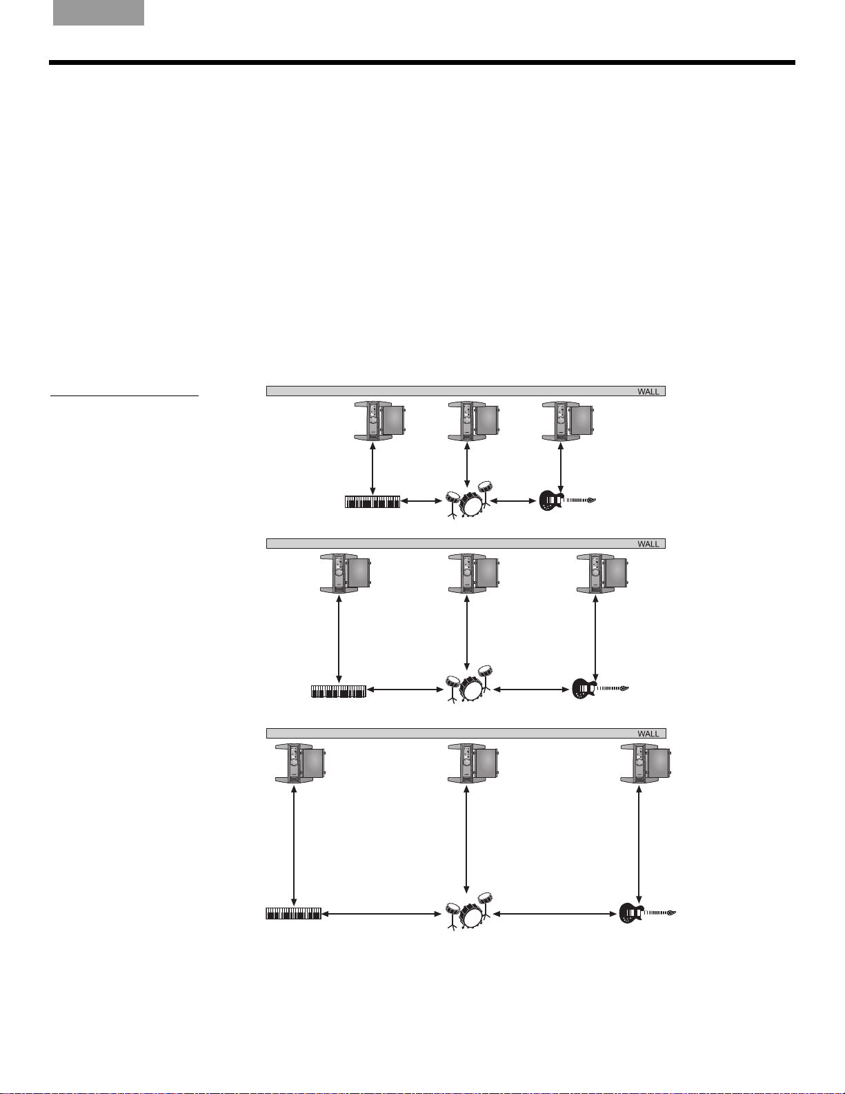
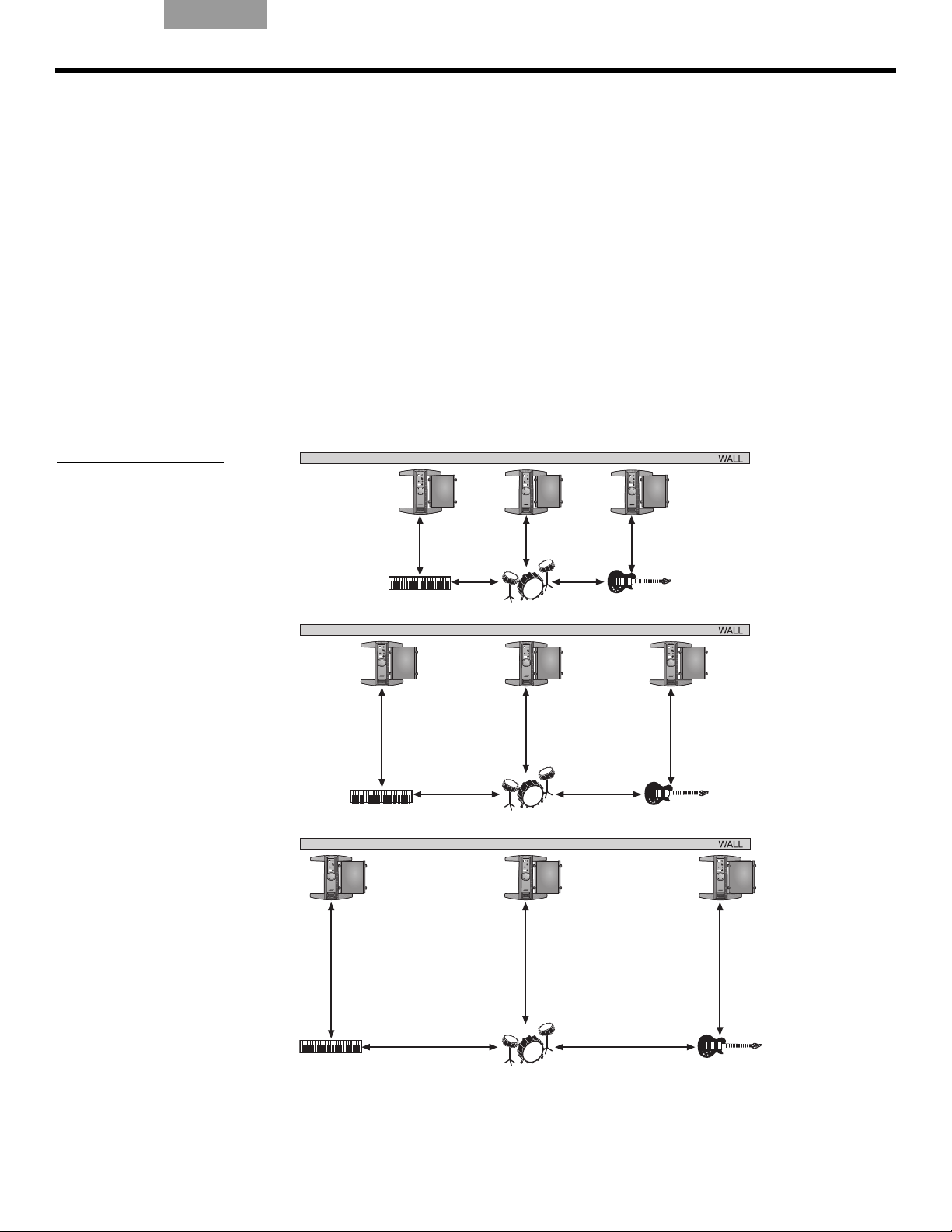
Positioning your system
Placing the power stand in the right location is an important part of setting up this product.
Determining the best location for your performance depends on several things.
• Size of staging area
• Number of performers
• Shared system (adding a T1 ToneMatch
The following guidelines should ge
• Set up your system in the rear area of the performance stage.
• If possible, position your system
• If you are part of a group, avoid crowding together on stage. Allow some distance,
ideally 7-8 feet (2.1-2.4 m), between you and the L1
performer. This allows the sound to wrap around performers and reflect off adjacent
surfaces of the room, cr
Figure 1
Placement
recommendations
®
audio engine and multiple instruments)
t you started in setting up for a concert or show.
behind the performer(s).
®
system and another
eating a more pleasing room-filling sound.
SYSTEM SETUP
9
Page 10
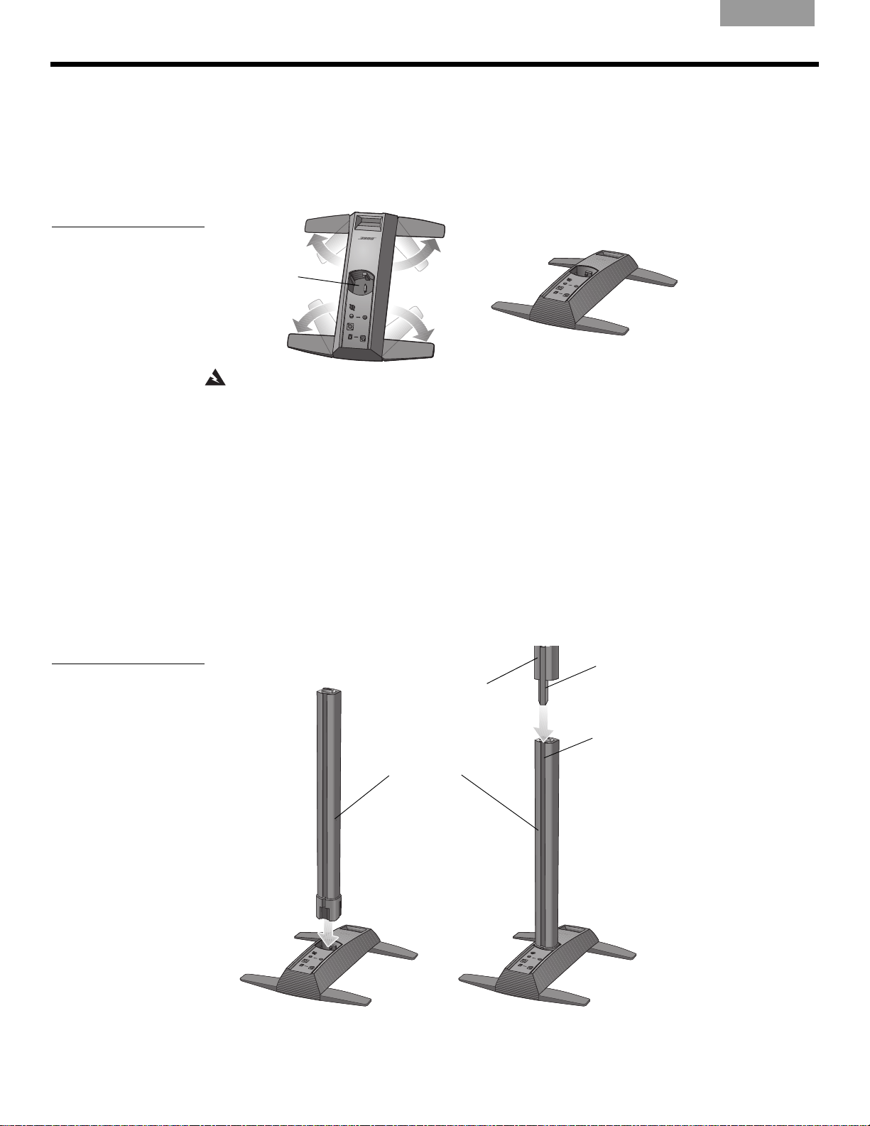
SYSTEM SETUP
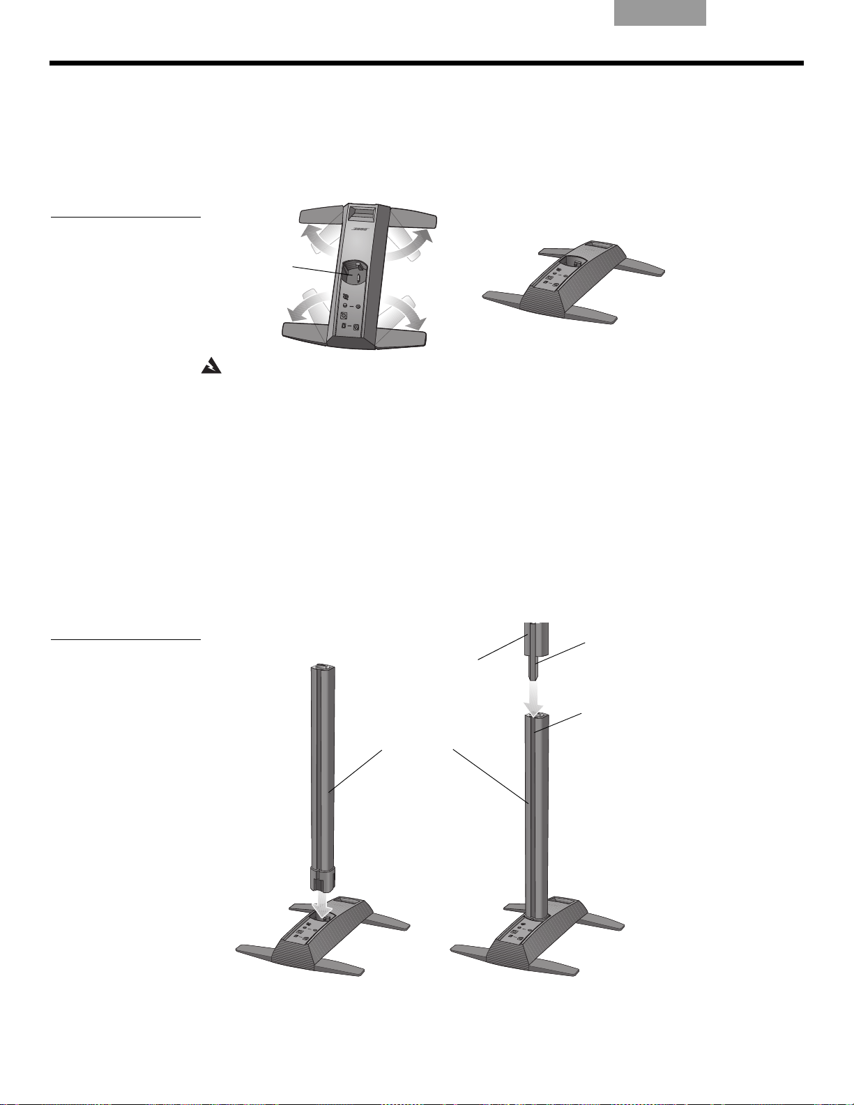
A
B
Socket for
L1 bottom
Top
array
Bottom
extension
Bayonet
Channel
A
B
Front of
system
Setting up the power stand
1. Holding the power stand vertically on the foor (Figure 2A), grasp one leg and swing it out
as far as it will go. Notice that the other legs swing out automatically. The legs must be
fully open
2. Lay the power stand flat on the floor in the desired position (Figure 2B).
Figure 2
Putting the power stand on
the floor
EnglishDeutschFrançais DanskEspañolItalianoSvenska Nederlands ItalianoSvenska DeutschNederlands Français Español
before you can plug the extension into the power stand.
WARNING: DO NOT move the completely assembled system as a unit. This could result in
personal injury and/or damage to the product. Position the power stand on the floor in the
chosen location before assembling the system.
Assembling the L1® model 1S system
This procedure tells you how to set up the loudspeaker sections in the power stand. If you
plan to mount the T1 ToneMatch
To ne M at c h
speaker.
1. Hold the bottom extension so that the cover faces front and plug it into the power stand
(Figure 3A). Be sure to fully insert it into the socket to assu
tion.
2. Align the bayonet on the top array with the channel on the back of the bottom, and lower
the top
Figure 3
Setting up the system
®
audio engine (optional)” on page 13 before installing the top array of the loud-
onto the bottom until it is flush (Figure 3B).
®
audio engine on the L1 model 1S system, see “Adding a T1
re stability and a good connec-
10
Page 11
English Deutsch FrançaisDansk Español Italiano SvenskaNederlandsItaliano SvenskaDeutsch NederlandsFrançaisEspañol
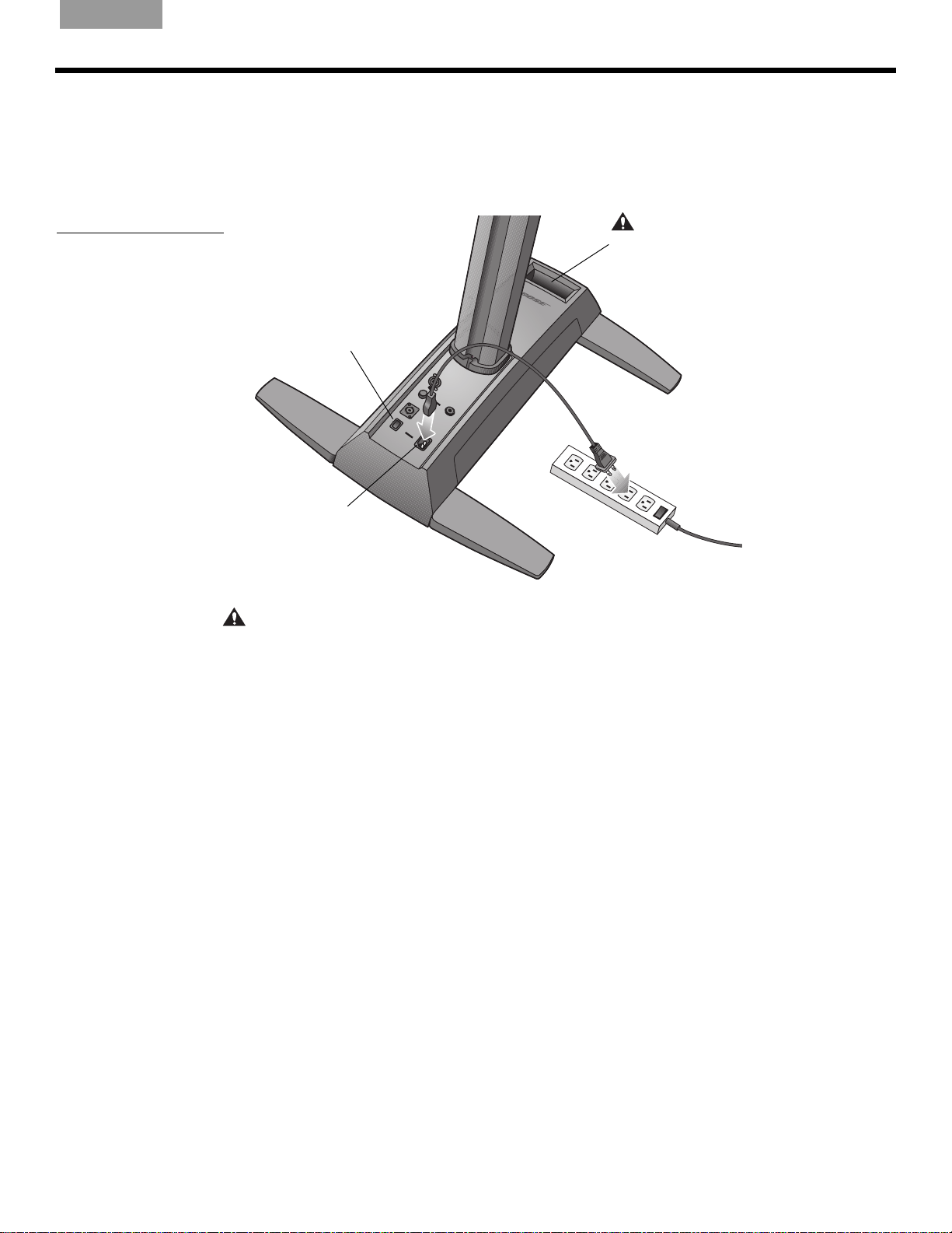
AC Mains
CAUTION: DO NOT block or cover
the handle opening, which is part of
the ventilation system. Doing so can
cause the L1
®
system to overheat,
switch to a thermal protection mode,
and temporarily turn off.
Power switch
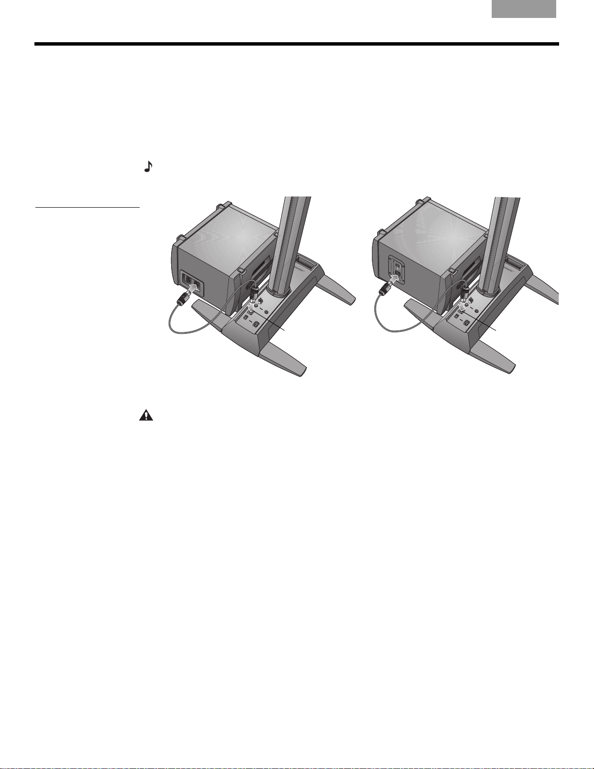
Connecting to AC power
1. Make sure the power switch is off.
2. Plug one end of the AC power cord into the AC Mains connec
3. Plug the other end into a live AC (mains) receptacle (Figure 4).
Figure 4
Power connections
SYSTEM SETUP
tor on the power stand.
CAUTION: Bose recommends using a quality surge suppressor on all electronic equipment.
Voltage variations and spikes can damage electronic components i
n any system. A quality
suppressor, which can eliminate the vast majority of failures attributed to surges, may be
purcha
sed at electronics stores.
11
Page 12
SYSTEM SETUP
B1
Bass Module
Out
Bass Module
Out
B2
Connecting the B1 or B2 bass module
You can place the B1 or B2 bass module either vertically or horizontally on the floor. It fits
neatly bewteen the legs of the power stand.
1. Plug one end of the B1 or B2 bass module cable into one of the bass connectors. Rotate
the plu
2. Plug the other end of the cable into the Bass Module Out co
stand. Rotate the plug clockwise to lock it.
Note:
the plug counterclockwise, and pull it out of the connector.
Figure 5
B1 and B2 bass modules
g clockwise to lock it in place. You should hear a soft click as it locks.
To disconnect a B1 or B2 cable, slide back the metal tab on the body of the plug, rotate
EnglishDeutschFrançais DanskEspañolItalianoSvenska Nederlands ItalianoSvenska DeutschNederlands Français Español
nnector on the power
CAUTIONS:
• DO NOT connect any bass module other than the B1 or B2 to the power stand.
• DO NOT substitute the supplied cable with a 2-wire speaker cable. Use only the supplied
B1 ba
power stand uses the signals on two of the wires to automatically sense how many B1 or
B2 bass modules are connected.
• DO NOT connect a B1 or B2 bass module to two power stands at the same time.
ss module 4-wire cable to connect the B1 bass module to the power stand. The
12
Page 13
English Deutsch FrançaisDansk Español Italiano SvenskaNederlandsItaliano SvenskaDeutsch NederlandsFrançaisEspañol
4
5
6
Carriage
Mounting bar
Bottom extension
T1 ToneMatch
audio engine
1
2
3
Locking knob
Power stand
Hook and loop strap
T1 ToneMatch
audio engine
Bottom
extension
ToneMatch cable
(supplied with T1)
ToneMatch
port
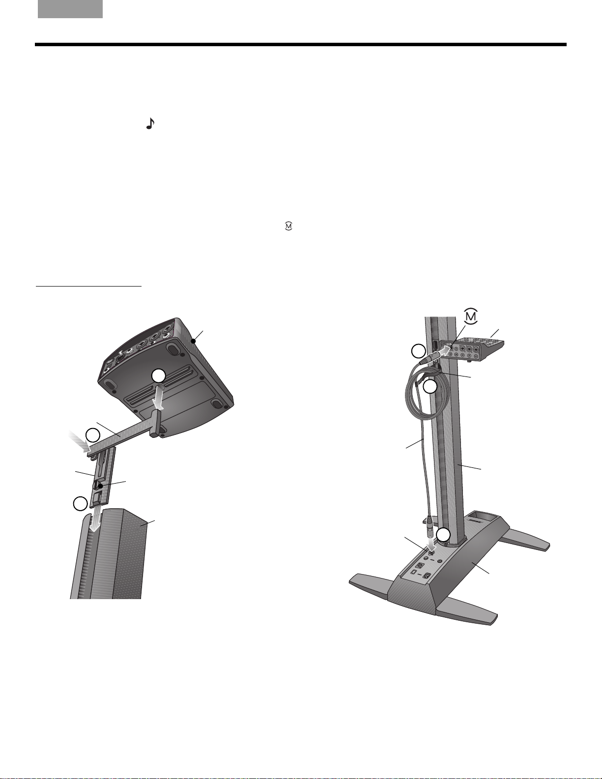
Adding a T1 ToneMatch® audio engine (optional)
The T1 ToneMatch® audio engine provides additional input/output capabilities to your
system, plus digital signal processing to customize
comes with hardware for mounting it on the left or right side of the bottom extension.
Note:
The audio engine mounts on the bottom section of the loudspeaker and requires removal
of the top section before starting this procedure.
1. Slide the carriage into the channel on the rear of the bottom extension and turn the knob
clock
wise to lock it in place (Figure 6).
2. Insert the mounting bar into the slot in the carriage and push it downward.
3. Place the T1 on the mounting bar as shown.
4. Plug one end of the ToneMatch cable (supplied with the audio engine) into the
ToneMatch output port (
5. Using the hook and loop strap, secure the cable to the carriage.
6. Plug the other end of the cable into the ToneMatch port on the power stand.
Figure 6
Mounting the T1
) on the T1.
SYSTEM SETUP
the way you sound. The audio engine
13
Page 14
SYSTEM SETUP
Second B1
bass module
cable
First B1 bass
module cable
Bass Module Out
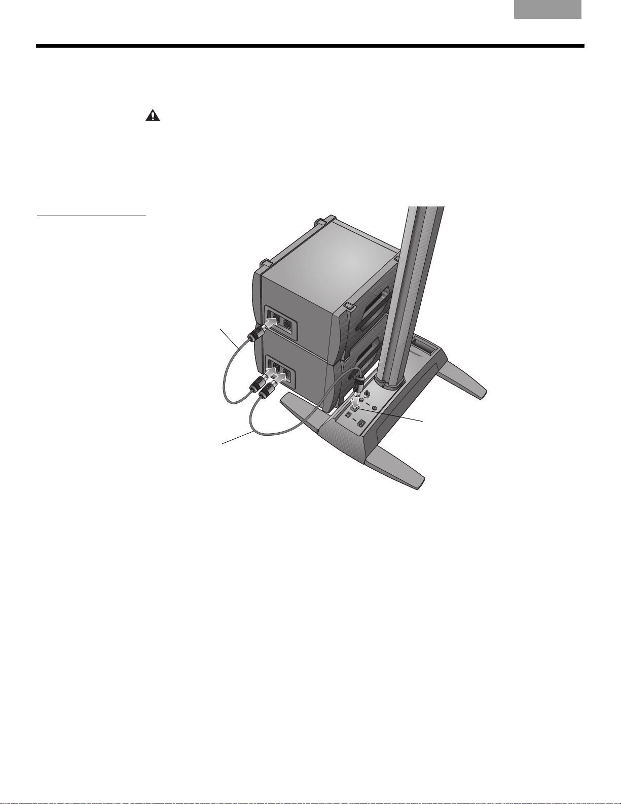
Adding a second B1 bass module (optional)
The bass module output of the power stand can adequately drive one or two B1 bass
modules. When placed horizontally, the modules are stackable (Figure 7).
EnglishDeutschFrançais DanskEspañolItalianoSvenska Nederlands ItalianoSvenska DeutschNederlands Français Español
Figure 7
Installation of two B1 bass
modules
CAUTION:
connector on the power stand. Driving more than two B1 bass modules from this output
Do not connect more than two B1 bass modules to the Bass Module Out
improperly loads the amplifier in the power stand, resulting in less than full system performance.
1. Connect the first B1 to the Bass Module
Out connector on the power stand.
2. Plug one end of the second B1 cable into the unused connector of the first B1. Plug the
other
end of the cable into one of the connecetors of the second B1.
14
Page 15

English Deutsch FrançaisDansk Español Italiano SvenskaNederlandsItaliano SvenskaDeutsch NederlandsFrançaisEspañol
OPERATING INFORMATION
OPERATING INFORMATION
Setting the analog input level
When connecting an audio source to the Analog Input, follow these steps to adjust the input
Trim control.
1.
Set the Trim control on the power stand to the 0 (zero) position.
2. Connect the audio source to the Analog Input.
3. Ad
4. While playing the source, increase the Tr
5. If the Signal/Clip ind
Using a T1 ToneMatch® audio engine and an analog input source
The L1® model 1S system can operate with both a T1 ToneMatch® audio engine and an
analog audio source connected to the power stand. However, keep in mind that the volume
level of
just the volume of the audio source to the desired level.
level until the Signal/Clip indicator glows
im
green or yellow.
icator glows red, decrease the Trim level so that it glows only green
or yellow.
the audio engine and the analog audio source is adjusted independently.
User scenarios
Figure 1
Single system with
keyboard
• The power stand Trim con
nected to the Analog Input.
of the analog input signal.
• The T1 ToneMatch audio engine has a Trim co
a Volume control for each output channel, and a Master volume control that adjusts the
level of the ToneMatch output sent to the power stand. These controls have no effect on
the signal fed to the Analog Input.
There are many ways to set up and use this system with and without the T1 ToneMatch audio
engine. The following pages show examples of some typical user scenarios. When using the
T1 ToneMatch audio engine, refer to its owner’s guide for more information on setup and
operation.
trol only affects the volume level of the analog audio source con-
Therefore, the Signal/Clip indicator indicates the status only
ntrol and signal/clip indicator for each input,
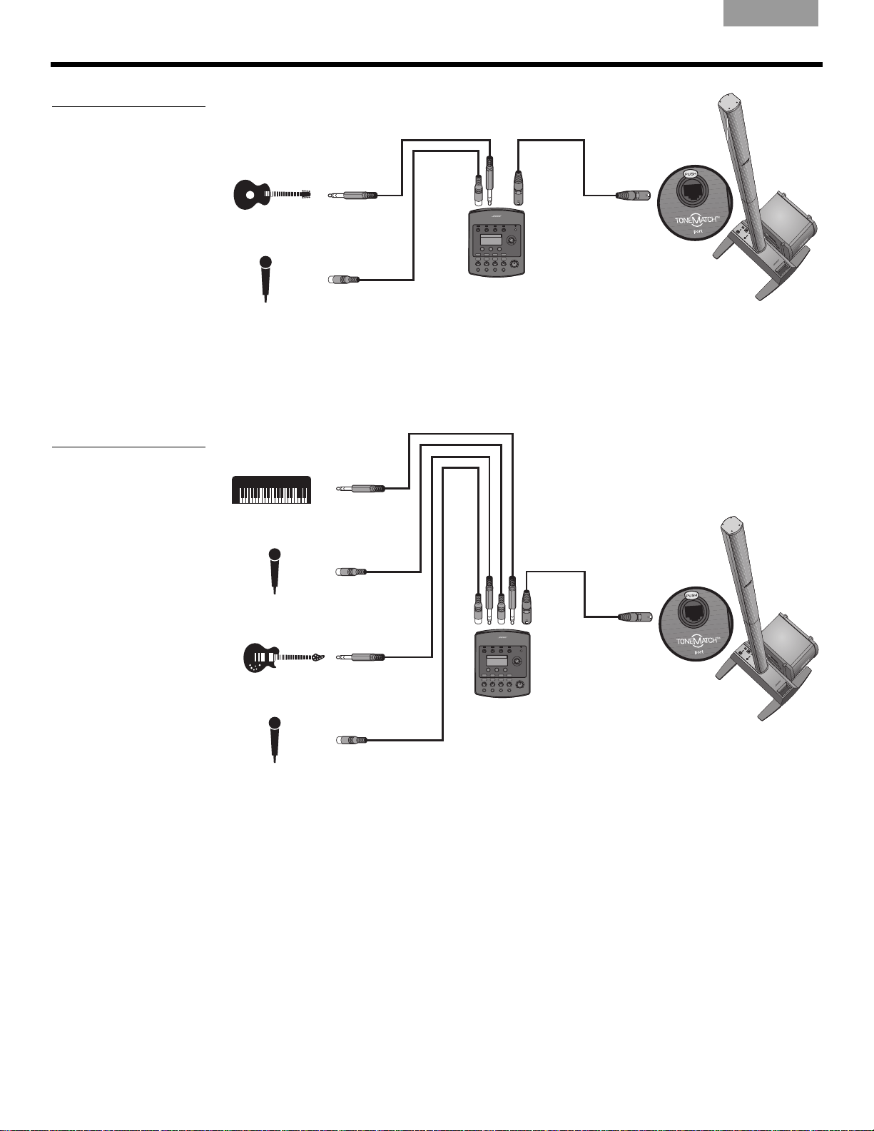
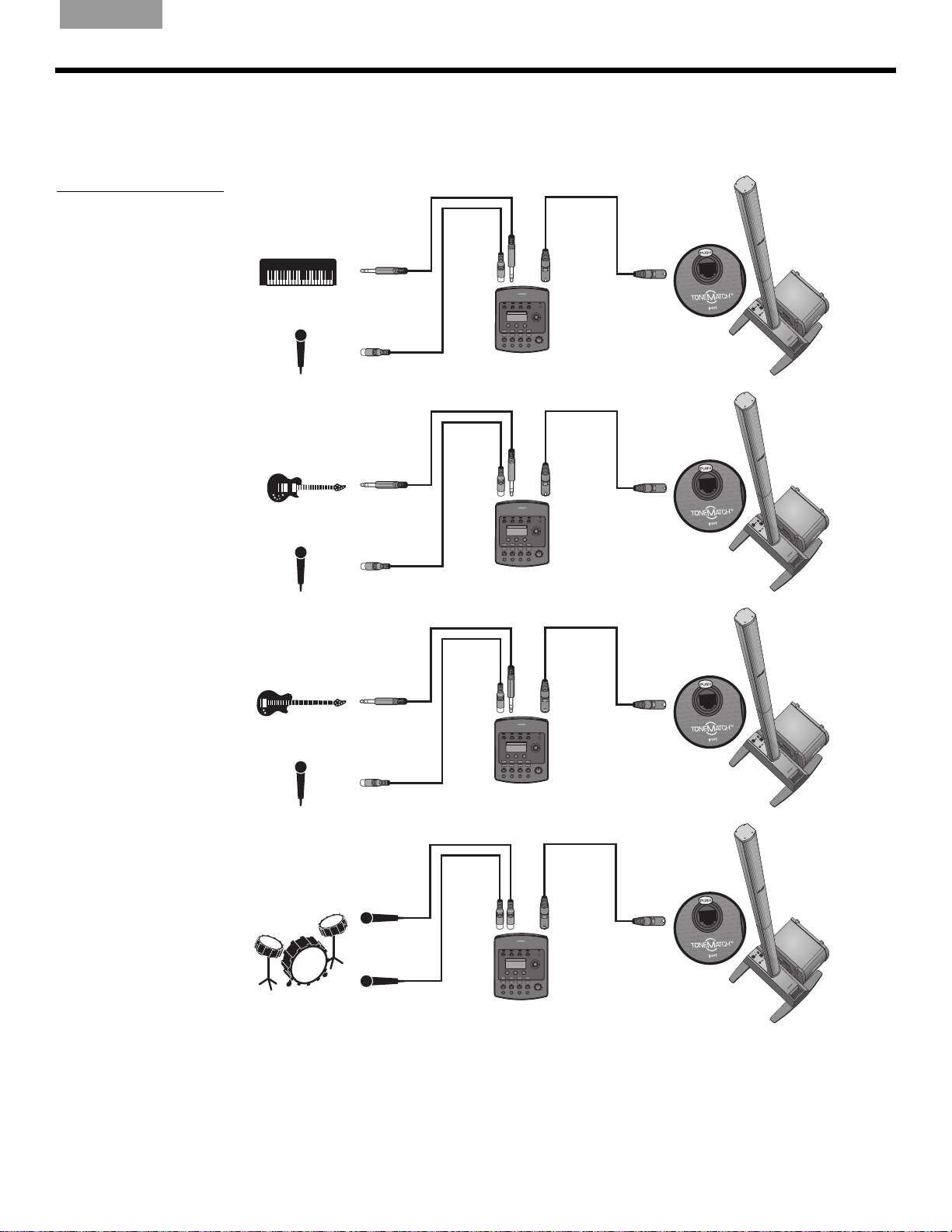
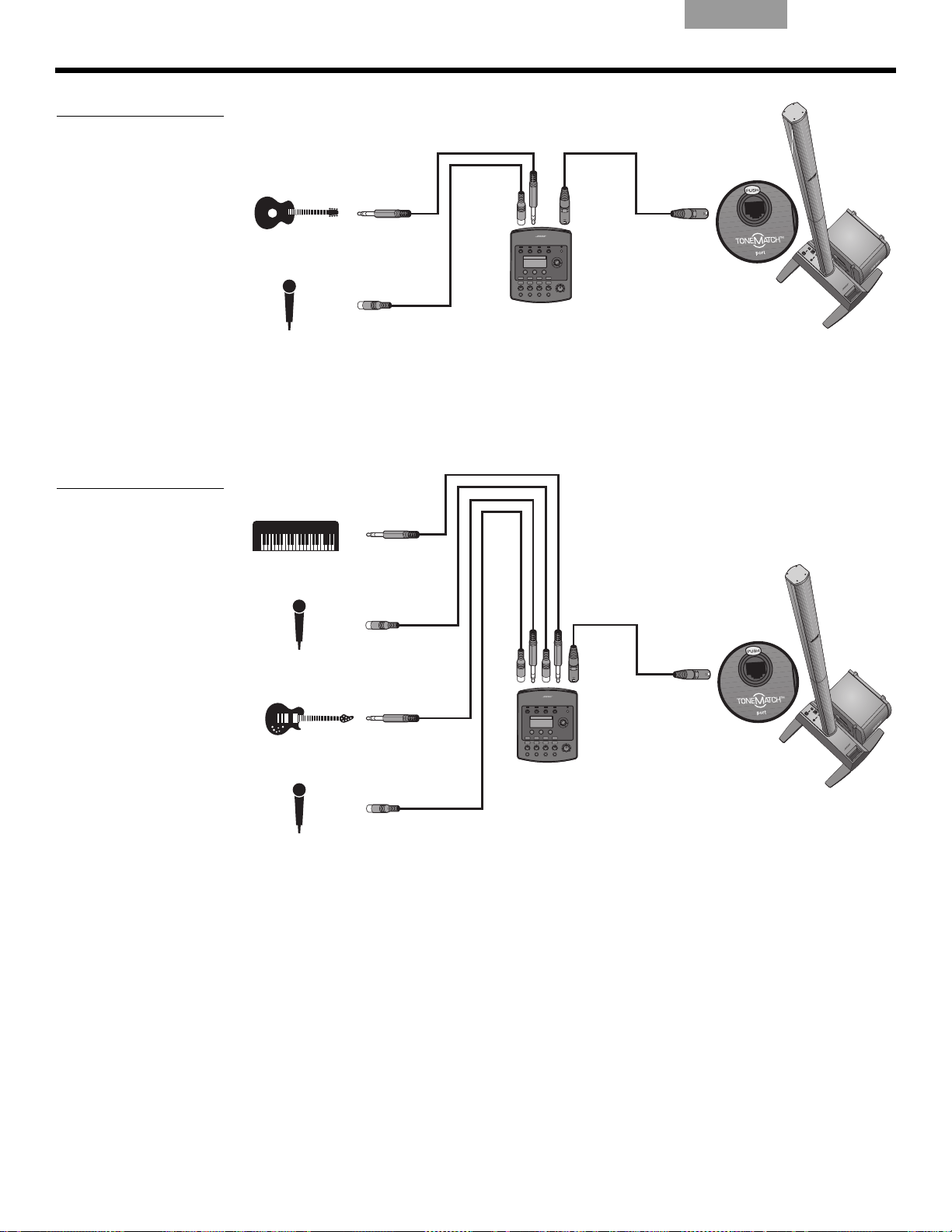
Single musician
A solo musician might play a single instrument through the L1 model 1S system (Figure 1).
A solo musician also might play an instrument and use a microphone for vocals (Figure 2 on
page 16).
15
Page 16
OPERATING INFORMATION
T1 ToneMatch®
audio engine
T1 ToneMatch
audio engine
Figure 2
Single system with
guitar and microphone
EnglishDeutschFrançais DanskEspañolItalianoSvenska Nederlands ItalianoSvenska DeutschNederlands Français Español
Multiple musicians
In this scenario, a keyboard-guitar duo sings and plays through a single T1 ToneMatch audio
engine and an L1
®
system.
Figure 3
Single system with
multiple instruments and
T1 ToneMatch audio engine
16
Page 17
English Deutsch FrançaisDansk Español Italiano SvenskaNederlandsItaliano SvenskaDeutsch NederlandsFrançaisEspañol
T1 ToneMatch
audio engine
T1 ToneMatch
audio engine
T1 ToneMatch
audio engine
T1 ToneMatch
audio engine
Figure 4
Multiple systems, each with
a T1 ToneMatch audio
engine
OPERATING INFORMATION
Full band
A full band scenario is built around multiple T1 ToneMatch® audio engines and L1® systems.
Each musician plays and sings through a single T1 ToneMatch audio engine and L1 system.
17
Page 18
OPERATING INFORMATION
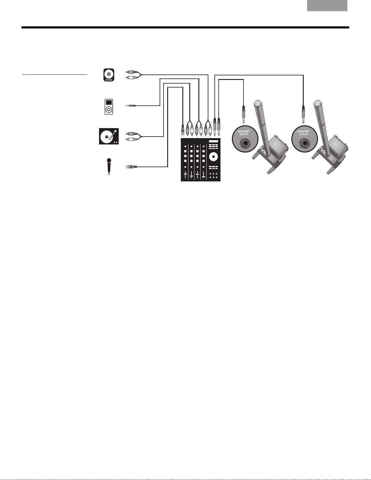
Figure 5
Two systems, a mixer, and
input devices
EnglishDeutschFrançais DanskEspañolItalianoSvenska Nederlands ItalianoSvenska DeutschNederlands Français Español
DJ events
DJs use many types of input sources (CD player, turntable, MP3 player, etc.) plugged into a
mixer. In this scenario, two mixer outputs can be fed into two L1
®
systems for stereo sound.
18
Page 19

English Deutsch FrançaisDansk Español Italiano SvenskaNederlandsItaliano SvenskaDeutsch NederlandsFrançaisEspañol
Caring for your product
Cleaning
• Clean the product enclosures using only a soft, dry cloth.
• Do not use any solvents, chemicals, or cleaning solutions containing alcohol, ammonia,
or abrasives.
• Do not use any sprays near the product or allow liquids to spill into any openings.
•
If necessary, you may carefully
Getting service
For additional help in solving problems, contact Bose® Live Music Customer Service Product
and Technical Support Team at (877) 335-2673 or visit our support area online at
www.Bose.com/livesound.
C
ARE AND MAINTENANCE
CARE AND MAINTENANCE
vacuum the grille of the L1® loudspeaker.
Troubleshooting
If you experience problems while using this product, try the following solutions. If you still
can’t solve the problem, please call the Bose Live Music Product and Technical Support
Team direct at (877) 335-2673 to arrange for service.
Recommended troubleshooting tools
• Portable voltmeter • XLR and ¼" phone plug cables
• Cable tester • B1 bass module 4-wire cable
• AC outlet tester • Spare AC power cord
Problem What to do
System is plugged in,
power switch is on, but
LED is off
power
Power LED is on (green),
but no sound
Power LED is red while the
power stan
d is on
• Make sure you have power at the AC outlet. Try operating a lamp or other equipment
fr
om the same AC outlet or test the outlet using an AC outlet tester.
• Make sure the power stand’s power cord plug is fully inserted into the AC outlet.
ake sure volume control is turned up on your instrument.
• M
• Make sure the Trim level
• Make sure your instrument is plugged into the Analog Input jack
• Connect your instrument to the power stand using a different cable.
• Plug your instrument into a different amplifier to
• Please call Bose Live Music Customer Support at (877) 335-2673 for assistance.
control is turned up on the power stand.
.
make sure the instrument is working.
House circuit breaker
keeps tripping
•
If more than one power stand is plugged into the same AC circuit, stagger the turn-on
times. Each power stand has an inrush current of about 32 amps when turned on.
• If you have more than three power stands plugged into a single 15 amp circuit, move
some sys
playing at high volumes for long periods of time.
tems to another AC circuit. Each power stand can draw 5 amps or more when
Venice_Care+Maint.fm 4/12
19
Page 20

C
ARE AND MAINTENANCE
Problem What to do
EnglishDeutschFrançais DanskEspañolItalianoSvenska Nederlands ItalianoSvenska DeutschNederlands Français Español
With nothing plugged into
the power stand, a slight
hum or buzz is heard
B1 or B2 bass module is
plugged
in, but no bass
audio is heard
B1 bass module sounds
of
balance with the
out
system
No mid/high sounds heard
from th
e L1
®
top array
Instrument or audio source
s distorted
sound
Microphone is
encountering feedback
• Using an AC outlet tester, test the AC outlet that the power stand is plugged into for
r
eversed or open (hot, neutral, and/or ground) contacts.
• If using an extension cord, make sure that the cord is also tested as above.
• Make sure you are using the included 4-wire B1/B2 bass module cable.
• Make sure the B1 or B2 bass module cable is plugged into the Ba
Module Out
ss
connector and the cable plug is fully engaged in the connector.
• Try a different 4-wire cable.
• If available, try a different B1/B2 bass module.
• Make sure you are using the B1/B2 bass module 4-wire cable included with the B1 bass
modu
le package.
• Make sure that the B1 or B2 bass
module grille is facing forward toward the musicians
and audience.
• Make sure the L1 top array and bottom extension are firmly seated in their connectors.
• Make sure connections are not bent or broken.
• Try cleaning the contacts on the loudspeaker top and bottom with electronic contact
y c
spra
leaner.
• Make sure the Signal/Clip LED is not constantly red. If it is, lower the trim level.
• Try a different source or instrument.
• Try your source or instrument on another power stand.
• Orient the microphone so that it is not pointing directly at its respective L1 system.
• Try a different microphone.
• Try a different position for the loudspeaker and/or vocalist on stage.
• Increase the distance from the loudspeaker to the microphone.
• If using a vocal effects processor, make sure it is not contributing to the feedback
problem.
20
Venice_Care+Maint.fm 4/12
Page 21

English Deutsch FrançaisDansk Español Italiano SvenskaNederlandsItaliano SvenskaDeutsch NederlandsFrançaisEspañol
Limited Warranty and Registration
Your product is covered by a limited warranty. Details of the warranty are provided with your
product. Register your products online at www.Bose.com/register or call (800) 905-1044.
Failure to do so will not affect your warranty rights.
Accessories
Visit www.Bose.com/livesound, or call (800) 905-0886 for accessory information.
Technical Information
Mechanical
Component Dimensions Weight
C
ARE AND MAINTENANCE
Power stand: 5''H x 10''W x
(12.8 cm x 26.2 cm x 69.2 cm)
Top array : 43½''H x
(111.0 cm x 9.0 cm x 10.5 cm)
Bottom extension: 39.63''H x
(100.6 cm x 10.6 cm x 10.5 cm)
B1 bass module: 15''H x
(38.0 cm x 26.0 cm x 45.0 cm)
B2 bass module: 23.4''H x
(59.4 cm x 33.8 cm x 48 cm)
3½''W x 4
4.15''W x
10¼''W x
13.31''W x
Electrical
•AC power rating:
100-120V
• Peak inrush current:
32A @ 120V
Component Impedance
®
L1
model 1S loudspeaker: 4
B1 bass module: 8
B2 bass module: 4
50/60Hz 500W (USA/Canada); 220-240V 50/60Hz 500W (Europe)
60Hz (USA/Canada); 61A @ 230V 50Hz (Europe)
27''D
17¾''D
''D
4.13''D
18.9''D
23.7 lb
(10.7 kg)
16.3 lb
(7.4 kg)
8.5 lb
(3.8 kg)
25.1 lb
(11.4 kg)
45 lb
(20.41 kg)
Audio Input/Output
• T1 ToneMatch® port: DC output/data input Ethercon/RJ45 connector for a
T1 ToneMatch audio engine
• Analog Input: Line-level input channel for ¼" TRS phone plug
• Bass Module Out: Neutrik
L1 and ToneMatch are registered trademarks of Bose Corporation in the U.S. and other countries.
All trademarks are the property of their respective owners.
Venice_Care+Maint.fm 4/12
®
NL4 output for one or two B1 bass modules
21
Page 22
SIKKERHEDSINFORMATION
Bedes udfyldt, så du har oplysningerne til rådighed
Det er en god idé at notere dit systems serienumre her og på dit produktregistreringskort nu. Du kan registrere
dit produkt online på www.Bose.com/register eller ringe på tlf. (800) 905-1044. Hvis du ikke gør det, har det
ingen betydning for din garanti.
L1
®
model 1S-forstærkerfod: ____________________________________________________________________
Topsektion og bundsektion:______________________________________________________________________
B1- eller B2-basmodul: _________________________________________________________________________
Læs venligst denne brugervejledning
Tag dig tid til at følge denne brugervejledning omhyggeligt. Den vil hjælpe dig med at installere og betjene systemet
korrekt, så du kan drage nytte af dets avancerede funktioner. Gem denne brugervejledning, så du har den til
rådighed senere.
ADVARSEL:
ADVARSEL:
serviceringen til kvalificere
Systemet må ikke udsættes for regn eller fugtighed af hensyn til risikoen for brand eller elektrisk stød.
Skil ikke systemet ad, medmindre du er kvalificeret til det, af hensyn til risikoen for elektrisk stød. Overlad
t servicepersonale.
Et lyn med pilehoved i en ligebenet trekant gør brugeren opmærksom på, at der i systemets kabinet kan
være uisoleret farlig spænding, der kan være så kraftig, at der er risiko for elektrisk stød.
EnglishDeutschFrançais DanskEspañolItalianoSvenska Nederlands
Mærket med et udråbstegn i en ligesidet trekant skal gøre brugeren opmærksom på vigtige betjenings- og
v
edligeholdels
FORSIGTIG:
FORSIGTIG:
overholdelse af lovbestemmelser samt systemets ydeev
FORSIGTIG:
FORSIGTIG:
komme til.
Bemærk: Produktet skal anvendes inden døre. Det er hverken designet eller testet til udendørs brug, brug i
fritidskøretøjer eller i både.
Dette produkt overholder alle gældende EU-regler. Den komplette overensstemmelseserklæring kan findes på:
www.Bose.com/compliance.
Dette produkt skal tilsluttes en stikkontakt med en beskyttende jordforbindelse.
Undlad at foretage ændringer i systemet eller tilbehøret. Uautoriserede ændringer kan sætte sikkerheden,
Placer ikke nogen form for åben ild (f.eks. stearinlys) på eller tæt ved apparatet.
Hvis netstikket eller apparatets tænd/sluk-knap anvendes som afbryder, skal denne afbryder være let at
esinstruktioner i denne brugervejledning.
ne over styr.
©2012 Bose Corporation. Gengivelse, ændring, distribution eller anden brug af dette dokument eller dele heraf er forbudt uden
forudgående skriftlig tilladelse.
2
Page 23

English Deutsch FrançaisDansk Español Italiano SvenskaNederlands
Oplysninger om produkter, der genererer
elektrisk støj
BEMÆRK: Dette udstyr er testet og fundet i
overensstemmelse med grænserne for en digital
Klasse A-enhed i henhold til afsnit 15 i FCC-reglerne.
Hensigten med disse grænser er at sikre tilstrækkelig
beskyttelse mod skadelig interferens, når udstyret
anvendes i et kommercielt miljø. Dette udstyr
genererer, bruger og kan udstråle radiofrekvensenergi,
og kan – hvis det ikke installeres og bruges i
overensstemmelse med brugervejledningen –
forårsage skadelig interferens i forbindelse med
radiokommunikation. Brug af dette udstyr i en privat
installation kan forårsage skadelig interferens, og i så
fald må brugeren få udbedret interferensen for egen
regning.
Ændringer eller modifikationer, der ikke udtrykkeligt er
godkendt af Bose Corporation, kan ophæve brugerens
ret til at betjene dette udstyr.
Dette produkt overholder den canadiske ICES-003
Klasse A-specifikation.
Initialt startstrømstød, når enheden tændes: 32 ampere
Inrush-strøm efter strømafbrydelse på 5 sekunder:
32 ampere
Dette produkt overholder alle EN55103-2
immunitetskrav for et E2 elektromagnetisk miljø.
VIGTIGE SIKKERHEDSINSTRUKTIONER
1. Læs disse instruktioner.
2. Gem disse instruktioner.
3. Ret dig efter alle advarsler.
4. Følg alle instruktioner.
5. Anvend ikke dette apparat i nærheden af vand.
6. Rengør kun med en tør klud.
7. Undgå at blokere ventilationsåbningerne.
Instal
ler i overensstemmelse med producentens
instruktioner.
8. Installer ikke produktet i nærheden af
varmekilder som f.eks. ra
komfurer eller andre apparater (herunder
forstærkere), der producerer varme.
9. Omgå ikke sikkerheden ved at bruge et
ikke
-jor
dforbundet stik. Et polariseret stik har to
stikben, hvor det ene er bredere end det andet.
Et jordforbundet stik har to ben og et tredje
jordben. Det brede ben eller tredje ben er der af
hensyn til din sikkerhed. Hvis det medfølgende
stik ikke passer i stikkontakten, skal du
kontakte en elektriker for at få stikkontakten
udskiftet.
10. Beskyt netledningen mod at blive trådt på eller
klemt,
det sted, hvor den kommer ud af apparatet.
11. Brug kun tilslutningsudstyr/tilbehør, der er
ang
12. Brug kun apparatet sammen med en
vogn, et st
der er angivet af producenten eller
solgt sammen med apparatet. Når der
anvende
forsigtighed ved kørsel med vogn/apparat,
så det ikke vælter.
13. Afbryd strømmen til apparatet under tordenvejr,
eller når
14.
Overlad al servicering til kvalificeret
servicepersonale.
påkrævet, hvis apparatet på nogen måde er
beskadiget, hvis f.eks. netledningen eller
stikket er beskadiget, der er blevet spildt
væske, eller der er kommet ting ind i apparatet,
hvis apparatet er blevet udsat for regn eller
fugt, ikke virker normalt eller er blevet tabt.
især ved stikk
ivet af pr
oducenten.
ativ,
s en vogn, skal der udvises
står ubrugt i lang tid.
det
ene, stikkontakter og på
et beslag eller et bord,
Et serviceeftersyn er
torer, varmeovne,
dia
15. Undgå at overbelaste stikkontakter,
fo
rlængerle
hensyn til risikoen for brand eller elektrisk stød.
16. Undgå, at genstande eller væske kommer ind i
pr
oduktet – de
med farlig spænding eller kortslutte dele, hvilket kan
medføre brand eller elektrisk stød.
17. Se på bagbeklædningen angående mærkater,
der er r
18. Brug korrekte strømkilder – tilslut produktet til en
korr
ekt strømkilde som beskrevet i
betjeningsvejledningen eller som markeret på
produktet.
19. Apparatet må ikke udsættes for dryp eller
vandstænk,
f.eks. en vase – må ikke placeres på apparatet.
dninger eller indbyggede stik af
kan komme i berøring med steder
eleva
nte for sikkerheden.
og
genstande fyldt med vand –
3
Page 24

EnglishDeutschFrançais DanskEspañolItalianoSvenska Nederlands
INDLEDNING 5
Velkommen . . . . . . . . . . . . . . . . . . . . . . . . . . . . . . . . . . . . . . . . . . . . . . . . . . . . . . . . . . . . . . . . . . . . . . . . . . . . . . . . . 5
Funktioner og fordele . . . . . . . . . . . . . . . . . . . . . . . . . . . . . . . . . . . . . . . . . . . . . . . . . . . . . . .
Produktoversigt . . . . . . . . . . . . . . . . . . . . . . . . . . . . . . . . . . . . . . . . . . . . . . . . . . . . . . . . .
Tilslutninger og betjeningsfunktioner . . . . . . . . . . . . . . . . . . . . . . . . . . . . . . . . . . . . . . . . . . . . . . . .
. . . . . . . . . . . . . . . . . . . 5
. . . . . . . . . . . . . . . . . . . . . 6
. . . . . . . . . . . . . . 7
OPSÆTNING AF SYSTEMET 8
Liste over dele . . . . . . . . . . . . . . . . . . . . . . . . . . . . . . . . . . . . . . . . . . . . . . . . . . . . . . . . . . . . . . . . . . . . . . . . . . . . . . . 8
Placering af dit system . . . . . . . . . . . . . . . . . . . . . . . . . . . . . . . . . . . . . . . . . . . . . . . . . . . . . .
Opsætning af forstærkerfoden . . . . . . . . . . . . . . . . . . . . . . . . . . . . . . . . . . . . . . . . . . . . . . . . . . . . .
Samling af L1
®
model 1S-systemet . . . . . . . . . . . . . . . . . . . . . . . . . . . . . . . . . . . . . . . . . . . . . . . . . . . . . . . . . . . . . . . 10
Tilslutning af vekselstrøm . . . . . . . . . . . . . . . . . . . . . . . . . . . . . . . . . . . . . . . . . . . . . . . . . . . . .
Tilslutning af B1- eller B2-basmodulet . . . . . . . . . . . . . . . . . . . . . . . . . . . . . . . . . . . . . . . . . . . . . . .
Tilføjelse af en T1 ToneMatch
®
-lydmotor (ekstraudstyr) . . . . . . . . . . . . . . . . . . . . . . . . . . . . . . . . . . . . . . . . . . . . . . . 13
Tilføjelse af et ekstra B1-basmodul (ekstraudstyr) . . . . . . . . . . . . . . . . . . . . . . . . . . . . . . . . . . . . . . . . .
. . . . . . . . . . . . . . . . . . . 9
. . . . . . . . . . . . . . 10
. . . . . . . . . . . . . . . . . . 11
. . . . . . . . . . . . . . 12
. . . . . . . . . . . 14
BETJENINGSOPLYSNINGER 15
Indstilling af analogt indgangsniveau . . . . . . . . . . . . . . . . . . . . . . . . . . . . . . . . . . . . . . . . . . . . . . . . . . . . . . . . . . . . . . 15
Brug af en T1 ToneMatch
Brugerscenarier . . . . . . . . . . . . . . . . . . . . . . . . . . . . . . . . . . . . . . . . . . . . . . . . . . . . . . . . .
Enkelt musiker . . . . . . . . . . . . . . . . . . . . . . . . . . . . . . . . . . . . . . . . . . . . . . . . . . . . . . . . . .
Flere musikere . . . . . . . . . . . . . . . . . . . . . . . . . . . . . . . . . . . . . . . . . . . . . . . . . . . . . . . . . .
Helt band . . . . . . . . . . . . . . . . . . . . . . . . . . . . . . . . . . . . . . . . . . . . . . . . . . . . . . . . . . . .
Dj-begivenheder . . . . . . . . . . . . . . . . . . . . . . . . . . . . . . . . . . . . . . . . . . . . . . . . . . . . . . . . . . .
®
-lydmotor og en analog indgangskilde . . . . . . . . . . . . . . . . . . . . . . . . . . . . . . . . . . . . . . . 15
. . . . . . . . . . . . . . . . . . . . . 15
. . . . . . . . . . . . . . . . 15
. . . . . . . . . . . . . . . . 16
. . . . . . . . . . . . . . . . . . 17
. . . . . . . . . . . . . . 18
PLEJE OG VEDLIGEHOLDELSE 19
Vedligeholdelse af produktet . . . . . . . . . . . . . . . . . . . . . . . . . . . . . . . . . . . . . . . . . . . . . . . . . . . . . . . . . . . . . . . . . . . . 19
Rengøring . . . . . . . . . . . . . . . . . . . . . . . . . . . . . . . . . . . . . . . . . . . . . . . . . . . . . . . . . . . . . .
Service . . . . . . . . . . . . . . . . . . . . . . . . . . . . . . . . . . . . . . . . . . . . . . . . . . . . . . . . . . . . . .
Fejlfinding . . . . . . . . . . . . . . . . . . . . . . . . . . . . . . . . . . . . . . . . . . . . . . . . . . . . . . . . . . . . .
. . . . . . . . . . . . . . . . . . . . . . 19
Begrænset garanti og registrering . . . . . . . . . . . . . . . . . . . . . . . . . . . . . . . . . . . . . . . . . . . . . . . . . .
Tilbehør . . . . . . . . . . . . . . . . . . . . . . . . . . . . . . . . . . . . . . . . . . . . . . . . . . . . . . . . . . . . . .
. . . . . . . . . . . . . . . . . . . . . . 21
Tekniske oplysninger . . . . . . . . . . . . . . . . . . . . . . . . . . . . . . . . . . . . . . . . . . . . . . . . . . . . . . . .
Mekanisk . . . . . . . . . . . . . . . . . . . . . . . . . . . . . . . . . . . . . . . . . . . . . . . . . . . . . . . . . . . . . .
Elektrisk . . . . . . . . . . . . . . . . . . . . . . . . . . . . . . . . . . . . . . . . . . . . . . . . . . . . . . . . . . . . .
Lydindgange/-udgange . . . . . . . . . . . . . . . . . . . . . . . . . . . . . . . . . . . . . . . . . . . . . . . . . . . . . . . .
. . . . . . . . . . . . . . . . 19
. . . . . . . . . . . . . . . . . . 19
. . . . . . . . . . . . . . 21
. . . . . . . . . . . . . . . . . . 21
. . . . . . . . . . . . . . . . 21
. . . . . . . . . . . . . . . . . . 21
. . . . . . . . . . . 21
4
Page 25

English Deutsch FrançaisDansk Español Italiano SvenskaNederlands
INDLEDNING
Velkommen
Tak fordi du har købt et Bose® L1® model 1S-system med ToneMatch®-port. Dette system er
baseret på en revolutionerende ny teknologi, der gør det muligt at udnytte fordelene ved den
intime akustiske koncert til forstærker understøttede optrædener.
Denne brugervejledning giver detaljer
L1-system og forklarer, hvordan du tilslutter udstyret til det.
På www.Bose.com/livesound på inte
systemet, herunder tip, teknikker og ofte stillede spørgsmål.
Funktioner og fordele
• Du styrer lyden – På samme måde som når du ikke bruger forstærker, er det dig,
der styrer lyden. Du behøver ikke længere bekymre dig om, hvordan du lyder over for de
øvrig
• Hurtig og let instal
nogle minutter, ikke timer. Hermed er du fri for det tidskrævende og ofte frustrerende
arbejde med at installere et konventionelt lydudstyr korrekt.
• Væse
præstationen og fornøjelsen væsentligt, da du ikke længere skal anstrenge dig for at høre
dig selv og de andre musikere.
• Skab
spænding og sindsbevægelse, som musikelskere værdsætter.
• Du hører, hvad publikum hører –
hører, og er derfor mindre tilbøjelige til at spille for højt.
• Musikken
høres og nydes.
• Du tager dig bedre ud – Der
de installations- og betjeningsvejledninger for dit
e
rnettet kan du finde yderligere oplysninger om brugen af
e musikere eller over for publikum, fordi du hører, hvad de hører.
lation – L1-systemet er let at bære og kan installeres i løbet af blot
ntlig præstationsforbedring –
er spænding og følelser –
er naturligt dynamisk – Alt fra de blødeste til de mest intense passager kan
er mindre udstyr på scenen og mere plads.
I forhold til traditionelt udstyr forbedres
Forbedret musikerpræstation skaber den form for
For første gang hører musikere, hvad deres publikum
• Lydgengivelse som aldrig før –
spænding, der opstår ved at høre den nøjagtige gengivelse af lyd fra hvert enkelt
instrument og ved at høre lyden af hvert enkelt instrument i dets position på scenen
(i modsætning til mono- eller selv s
hørt ved en forstærker understøttet optræden.
Personer blandt publikum fortæller, at den klarhed og
t
ereomix af alle instrumenter), ikke ligner noget, de har
5
Page 26
I
Topsektion
Forstærkerfod
L1 model 1S-system med ToneMatch-port og B1-basmodul
Ekstraudstyr
B1-basmodul
T1 ToneMatchlydmotor
Ekstra B1basmodul
B2-basmodul
Bundsektion
NDLEDNING
Produktoversigt
Figur 1
L1 model 1S-system og
ekstraudstyr
EnglishDeutschFrançais DanskEspañolItalianoSvenska Nederlands
L1® model 1S-system – med ToneMatch®-port består af: forstærkerfod, bundsektion,
topsektion og et B1- eller B2-basmodul. Systemet leveres med en polstret taske til hver
enkelt del.
For at udvide systemet og forbedre præstationen kan du tilføje:
• Et ekstra B1-basmodul til en basguitar, en stortromme elle
r et orgel. Hver forstærkerfod kan
drive op til to B1-basmoduler.
• En T1 ToneMatch-lydmotor til digital signalbehandling, yderligere indgange og
interf
acekontrol.
Du finder en komplet liste over ekstraudstyr og tilbehør på www.Bose.com/livesound.
6
Page 27
English Deutsch FrançaisDansk Español Italiano SvenskaNederlands
Hovedafbryder
Tænder og slukker
systemet.
AC Mains
Indgangsstik til
strømforsyning.
Bass Module Out
Basudgangssignal til at drive et
eller to B1-basmoduler. Passer til
et 4-leder basmodulkabel.
Trim
Justerer det analoge
indgangssignals niveau.
Ton eM atc h
®
-port
Digital lyd- og
strømforbindelse til
ekstraudstyret T1
ToneMatch-lydmotor.
Passer til det medfølgende
To ne M at ch - ka b el .
Analog Input
En analog linjeniveauindgang.
Passer til et ¼" TRS-telefonkabel.
Benyttes til et instrument eller en
anden lydkilde.
Signal/Clip-lysdiode
Angiver status for det analoge
indgangssignal.
Grøn = normal indgang
Gul = indgang nærmer sig forvrængning
Rød = indgangsforvrængning
Power/Fault-lysdiode
Angiver status.
Blå = systemet er tændt
Rød = systemfejl
Tilslutninger og betjeningsfunktioner
Toppanelet på effektforstærkeren er udstyret med systemtilslutninger og betjeningsknapper
(Figur 2).
Figur 2
Toppanel på
effektforstærker
I
NDLEDNING
7
Page 28
OPSÆTNING AF SYSTEMET
L1TM Model II System
with ToneMatchTM port
Owner’s Guide
www.Bose.com/musicians
Overdel
Underdel
B1
Bass Module
Installation Guide
Oversigt over delene
L1®-systemet leveres i tre kasser. Pak forsigtigt kasserne ud, og kontroller, at du har alle de
dele, der er angivet på denne side.
ADVARSEL:
Kasse med forstærkerfod Kasse med sektion og udvidelse Kasse med B1- eller B2-basmodul
Opbevar plastikposerne utilgængeligt for børn for at undgå risikoen for kvælning.
EnglishDeutschFrançais DanskEspañolItalianoSvenska Nederlands
L1-forstærkerfod
Transporttaske
Netledning
Hurtig installations- Brugervejledning vejledning
L1 model 1S-topsektion og
bundsektion
Transporttaske
B1- eller B2-basmodul
Låg
Basmodulkabel (4-leder)
Selvklæbende gummifødder
(kun til B2)
Produktregistreringskort
Brugervejledning til B1- eller
B2-basmodul
8
Page 29
English Deutsch FrançaisDansk Español Italiano SvenskaNederlands
God
Bedre
Bedst
0,9 m
1,5 m
2,1-2,4 m
0,9 m 0,9 m
0,9 m0,9 m
1,5 m1,5 m
1,5 m 1,5 m
2,1-2,4 m
2,1-2,4 m
2,1-2,4 m 2,1-2,4 m
Placering af dit system
Korrekt placering af forstærkerfoden er et vigtigt trin i opstillingen af dette produkt.
Den bedste placering for din optræden afhænger af flere ting.
• Scenens størrelse
• Antal optrædende
®
• Delt system (tilføjelse af en T1 ToneMatch
De følgende retningslinjer hjælper dig i gang med opstillingen til en koncert eller et show
-lydmotor og flere instrumenter)
OPSÆTNING AF SYSTEMET
.
Figur 1
Anbefalinger for placering
• Opstil dit system på den bageste del af det om
råde, hvor du skal optræde.
• Placer om muligt systemet bag den/de optrædende.
• Undgå at stå for tæt på hinanden på scenen, hvis du er en del af en gruppe.
Lav afst
and, helst 2,1-2,4 m mellem dig selv og L1
®
-systemet og en anden
optrædende. Hermed kan lyden folde sig rundt om de optrædende og blive kastet
tilbage fra omgivende overflader i rummet, hvorved der skabes et mere behageligt
rumudfyldende lydbillede.
9
Page 30
OPSÆTNING AF SYSTEMET
A
B
Fatning til
L1-underdel
Topsektion
Bundsektion
Spyd
Kanal
A
B
Systemets
forside
Opsætning af forstærkerfoden
1. Hold forstærkerfoden lodret på gulvet (Figur 2A), tag fat i et ben og sving det så langt ud,
som det kan komme. Bemærk, at de andre ben svinger automatisk ud. Benene skal
vær
e helt åbne, før du kan sætte udvidelsen i forstærkerfoden.
2. Læg forstærkerfoden fladt ned på gulvet i den ønskede position (Figur 2B).
Figur 2
Placering af
forstærkerfoden på gulvet.
ADVARSEL: UNDLAD at flytte hele det samlede system som en enhed. Dette kan forårsage
personskade og/eller beskadigelse af produktet. Placer forstærkerfoden på det ønskede sted på
gulvet, før du samler systemet.
EnglishDeutschFrançais DanskEspañolItalianoSvenska Nederlands
Samling af L1® model 1S-systemet
Denne procedure forklarer, hvordan du skal placere højttalersektionerne i forstærkerfoden.
Hvis du planlægger at montere T1 ToneMatch
du se “Tilføjelse af en T1 ToneMatch
den øverste sektion af højttaleren.
1. Hold bundsektionen, således at kabinettet vender fremad, og sæt den så ned i
forstæ
rkerfoden (Figur 3A). Sørg for at sætte den helt ned i fatningen for at sikr
og en god forbindelse.
2. Ret spyddet på topsektionen ind efter kanalen på bagsiden af underdelen, og sænk
overde
Figur 3
Opsætning af systemet
len ned i underdelen, indtil de går helt sammen (Figur 3B).
®
®
-lydmotor (ekstraudstyr)” på side 13, før du monterer
-lydmotoren på L1 model 1S-systemet, skal
e stabilitet
10
Page 31

English Deutsch FrançaisDansk Español Italiano SvenskaNederlands
AC Mains
FORSIGTIG: UNDLAD at
blokere eller tildække
håndtagsåbningen, som er en
del af ventilationssystemet.
Hvis du gør dette, kan L1
®
systemet overophede,
skifte over til termisk
beskyttelsestilstand og
midlertidigt slukke.
Hovedafbryder
Tilslutning af vekselstrøm
1. Sørg for, at strømkontakten er slukket (OFF).
2. Sæt den ene ende af netledningen ind i AC Ma
3. Sæt netledningens anden ende ind i en fungerende stikkontakt. (Figur 4).
Figur 4
Strømtilslutning
ins-stikket på forstærkerfoden.
OPSÆTNING AF SYSTEMET
FORSIGTIG: Bose anbefaler, at man bruger en overspændingsafleder af god kvalitet til alt
elektronisk udstyr. Spændingsvariationer og -spidser kan beskadige elektroniske komponenter i
alle systemer. En afleder af
god kvalitet kan forhindre de fleste tilfælde af svigt forårsaget af
overspænding og kan købes i elektronikforretninger.
11
Page 32

OPSÆTNING AF SYSTEMET
B1
Bass Module
Out
Bass
Module Out
B2
Tilslutning af B1- eller B2-basmodulet
Du kan placere B1- eller B2-basmodulet enten lodret eller vandret på gulvet. Det passer fint
mellem benene på effektforstærkeren.
EnglishDeutschFrançais DanskEspañolItalianoSvenska Nederlands
Figur 5
B1- og B2-basmoduler
1. Tilslut den ene ende af B1- eller B2-basmodulkablet i det en
med uret for at fastlåse det. Du hører et svagt klik, når det fastlåses.
2. Sæt den anden ende af kablet ind i Bass Module
Drej stikket med uret for at fastlåse det.
Bemærk:
dreje stikket mod uret og trække det ud af enheden.
Et B1- eller B2-kabel tages ud ved at skubbe metalpalen på stikkets krop tilbage,
Out-stikket på forstærkerfoden.
e af basstikkene. Drej stikket
FORSIGTIG:
• Tilslut IKKE noget andet basmodul end B1 eller B2 til forstærkerfoden.
• Erstat IKKE det medfølgende kabel med et 2-leder-højttalerkabel. Brug kun det
medføl
Forstærkerfoden bruger signalerne på to af lederne til automatisk at registrere, hvor mange
B2-basmoduler der er tilsluttet.
• Tilslut IKKE et B1- eller B2-basmodul til to forstærkerfødder på samme tid.
gende 4-leder B1-basmodulkabel til at tilslutte B1-basmodulet til forstærkerfoden.
12
Page 33

English Deutsch FrançaisDansk Español Italiano SvenskaNederlands
4
5
6
Slæde
Monteringsstang
Bundsektion
T1 ToneMatchlydmotor
1
2
3
Låseknap
Forstærkerfod
Krog og løkke
T1 ToneMatchlydmotor
Bundudvidelse
ToneMatch-kabel
(følger med T1)
ToneMatch-port
Tilføjelse af en T1 ToneMatch®-lydmotor (ekstraudstyr)
T1 ToneMatch®-lydmotoren giver dit system yderligere indgangs-/udgangsfunktioner plus
digital signalbehandling, således at du kan justere, hvordan du lyder. Lydmotoren leveres
med beslag til montering på venstre eller højre side af bundsektionen.
OPSÆTNING AF SYSTEMET
Figur 6
Montering af T1
Bemærk:
Lydmotoren monteres på underdelen af højttaleren, og du skal fjerne overdelen, før du
starter denne procedure.
1. Skub slæden ind i kanalen på bagsiden af bundsektionen, og drej knappen med uret for
at fastlåse den (Figu
r 6).
2. Sæt monteringsstangen ind i rillen i slæden, og skub den nedad.
3.
Placer T1 på monteringsstangen som vist.
4. Sæt den ene ende af ToneMatch-kablet (leveres med lydmotoren) ind i ToneMatchudgan
gsporten (
) på T1.
5. Brug krogen og løkken, og fastgør kablet til slæden.
6. Sæt den anden ende af kablet ind i ToneMatch-porten på forstærkerfoden.
13
Page 34

OPSÆTNING AF SYSTEMET
Andet B1basmodulkabel
Første B1basmodulkabel
Bass Module Out
Tilføjelse af et ekstra B1-basmodul (ekstraudstyr)
Forstærkerfodens basmoduludgang kan udmærket drive et eller to B1-basmoduler.
Når de placeres vandret, kan modulerne stables (Figur 7).
EnglishDeutschFrançais DanskEspañolItalianoSvenska Nederlands
Figur 7
Installation af to
B1-basmoduler
FORSIGTIG:
Undlad at slutte mere end to B1-basmoduler til Bass Module Out-stikket på
forstærkerfoden. Hvis der drives mere end to B1-basmoduler fra denne udgang, bliver
forstæ
rkeren i forstærkerfoden belastet forkert, hvorved systemets ydeevne ikke bliver optimal.
1. Tilslut det første B1 til Bass Module Out-stikk
et på forstærkerfoden.
2. Sæt den ene ende af det andet B1-kabel ind i det ledige stik på det første B1. Sæt den
anden e
nde af kablet i et af stikkene på det andet B1.
14
Page 35

English Deutsch FrançaisDansk Español Italiano SvenskaNederlands
BETJENINGSOPLYSNINGER
Indstilling af analogt indgangsniveau
Ved tilslutning af en lydkilde til Analog Input skal du følge disse trin for at justere indgangens
Trim -regulering.
1.
Sæt Trim -knappen på effektforstærkeren på positionen 0 (nul).
2. Tilslut lydkilden til Analog Input.
3. Ju
ster lydstyrken på lydkilden til det ønskede niveau.
4. Afspil kilden, og forøg Trim -niv
5. Hvis Signal/Clip-indikat
grønt eller gult.
Brug af en T1 ToneMatch®-lydmotor og en analog indgangskilde
L1® model 1S-systemet kan fungere med både en T1 ToneMatch®-lydmotor og en analog
lydkilde tilsluttet forstærkerfoden. Du skal imidlertid huske, at lydmotoren og den analoge
lydkildes lydstyrke justeres uafhængigt af hinanden.
• Forstærkerfodens Tr
tilsluttet Analog Input. Derfor angiver Signal/Clip-indikatoren kun status for det analoge
indgangssignal.
• T1 ToneMatch-lydmotoren har en Tr
indgang, en Volume-regulering for hver udgangskanal og en Master-lydregulering,
der justerer niveauet for det ToneMatch-output, der sendes til forstærkerfoden.
Diss
guleringer har ingen indvirkning på det
e re
ontrol påvirker kun lydstyrken for den analoge lydkilde, som er
im-k
eauet, indtil Signal/Clip-indikatoren lyser grønt eller gult.
oren lyser rødt, så sænk Tri m-niveauet, indtil den kun lyser
egulering og en signal/clip-indikator for hver
im-r
signal, der sendes til Analog Input.
Brugerscenarier
Figur 1
Enkelt system med
keyboard
Der er mange måder at opsætte og benytte dette system på med og uden T1 ToneMatchlydmotoren. De følgende sider viser eksempler på nogle typiske brugerscenarier.
Når T1 ToneMatch-lydmotoren benyttes, henvises til brugerv
oplysninger vedrørende opsætning og betjening.
ejledningen
for yderligere
Enkelt musiker
En solomusiker kan spille et enkelt instrument via L1 model 1S-systemet (Figur 1).
En solomusiker kan også spille et instrument og bruge en mikr
side 16).
ofon til sang (Figur 2 på
15
Page 36
BETJENINGSOPLYSNINGER
T1 ToneMatch®-
lydmotor
T1 ToneMatch-
lydmotor
Figur 2
Enkeltsystem med guitar og
mikrofon
EnglishDeutschFrançais DanskEspañolItalianoSvenska Nederlands
Flere musikere
I dette scenarie synger og spiller en keyboard/guitar-duo via en enkelt T1 ToneMatchlydmotor og et L1
®
-system.
Figur 3
Enkelt system med flere
instrumenter og T1
ToneMatch-lydmotor
16
Page 37

English Deutsch FrançaisDansk Español Italiano SvenskaNederlands
T1 ToneMatch-
lydmotor
T1 ToneMatch-
lydmotor
T1 ToneMatch-
lydmotor
T1 ToneMatch-
lydmotor
Helt band
Et helt band-scenarie er opbygget omkring flere T1 ToneMatch®-lydmotorer og L1®-systemer.
Hver musiker spiller og synger via én T1 ToneMatch-lydmotor og ét L1-system.
Figur 4
Flere -systemer, hver med
en T1 ToneMatch-lydmotor
BETJENINGSOPLYSNINGER
17
Page 38

BETJENINGSOPLYSNINGER
Figur 5
To systemer, en mixer og
inputenheder
EnglishDeutschFrançais DanskEspañolItalianoSvenska Nederlands
Dj-arrangementer
Dj’s bruger mange typer indgangskilder (cd-afspiller, grammofon, mp3-afspiller osv.) tilsluttet
en mixer. I dette scenarie kan to mixerudgange fødes ind i to L1
®
-systemer mhp. stereolyd.
18
Page 39

English Deutsch FrançaisDansk Español Italiano SvenskaNederlands
PLEJE OG VEDLIGEHOLDELSE
Vedligeholdelse af produktet
Rengøring
• Produktets kabinetter må kun rengøres med en blød, tør klud.
Fejlfinding
• Brug ikke opløsningsmidler, kemikalier eller re
ammoniak eller slibemiddel.
• Brug ikke nogen form for spray i nærheden af system
åbningerne.
• Du kan om nødvendigt forsigtigt støvsuge gitteret på L1
ngøringsmidler, der indeholder sprit,
et, og undgå at spilde væske i
®
-højttaleren.
Service
For at få yderligere hjælp med at løse problemer kan du kontakte Bose® Live Music Customer
Service Product and Technical Support Team på tlf. (877) 335-2673 eller besøge vores
supportsider på internettet på www.Bose.com/livesound.
Prøv følgende løsningsmuligheder, hvis du får problemer med produktet. Hvis du stadig ikke
kan løse problemet, kan du ringe til Bose Live Music Product and Technical Support Team
direkte på tlf. (877) 335-2673 for at aftale service.
Anbefalede fejlfindingsværktøjer
• Bærbart voltmeter • XLR- og ¼"-telefons
• Kabeltester • 4-leder-kabel til B1-basmodul
• Spændingsmåler • Ekstra netledning
tikkabler
Problem Gør følgende
Systemet er tilsluttet,
afbryderknappen står
ndt, men
på tæ
s
trømindikator
Strømindikatoren er tændt
(
lyse
r grønt), men der er
ingen lyd
Strømindikatoren lyser
rødt, nå
er tændt
Husets strømafbryder
es konstant
udløs
en lyser ikke
r forstærkerfoden
• Kontroller, at der er strøm i vægstikket. Prøv at tilslutte en lampe eller andet udstyr i
samme
• Sørg for, at netledningen til forstærkerfoden er sat ordentligt i vægstikket.
• Sørg for, at der er skruet op for lyden til dit instrument.
• Sørg for, at der er skruet op for Tr
• Sørg for, at instrumentet e
• Tilslut dit instrument til forstærker
• Tilslut instrumentet til en anden forstærker for at sikre dig, at det fungerer.
• Kontakt Bose Live Music Customer Ser
• Hvis mere end én forstærkerfod er tilsluttet den samme strømkreds, skal du forsøge at
tænde forstærkerne med en tidsforskydning. Hver forstærkerfod har en inrush-strøm på
ca. 32 ampere, når den tændes.
• Hvis du har mere end tre forstærkerfødder tilsluttet en enkelt 15 amperes kreds,
så forsøg at flytte nogle systemer til en anden kreds. Hver forstærkerfod kan trække
5 ampere eller mere, når den spiller ved høj lydstyrke
stikkontakt, eller test stikket med en spændingsmåler.
im-n
iveaureguleringen på forstærkerfoden.
r tilsluttet Analog Input-jackstikket.
foden med et andet kabel.
vice på tlf. (877) 335-2673 for hjælp.
i længere
perioder.
19
Page 40

P
LEJE OG VEDLIGEHOLDELSE
Problem Gør følgende
EnglishDeutschFrançais DanskEspañolItalianoSvenska Nederlands
Når der ikke er tilsluttet
noget til forstærkerfoden,
høres en svag brummen
eller snurren
B1- eller B2-basmodul er
t
ilslu
ttet, men der er ingen
baslyd
B1-basmodulet lyder,
so
med de
er ude af balance
m det
t øvrige system
Der høres ingen
m
e
llemhøje/høje lyde fra
®
L1
-topsektionen
Instrument eller lydkilde
lyde
r forvrænget
Der opstår feedback i
mikr
ofonen
• Brug en spændingsmåler til at kontrollere den stikkontakt, som forstærkerfoden er
t
ilsluttet, for omvendte eller åbne kontakter (spændingsførende, neutral og/eller jord).
• Hvis du bruger en forlængerledning, skal du sørge for, at den også testes som ovenfor.
• Sørg for, at du bruger det medfølgende 4-leder B1/B2-basmodulkabel.
• Sørg for, at B1- eller B2-basmodulkablet er
tilsluttet Ba
ss Module Out-stikket,
og kablets stik er sat forsvarligt ind i stikket.
•
Prøv med et andet 4-leder-kabel.
• Prøv om muligt med et andet B1/B2-basmodul.
• Sørg for, at du bruger det 4-leder B1/
B2-basmodu
lkabel, der fulgte med
B1-basmodulpakken.
• Sørg for, at gitteret på B1- eller B2-basmodulet vender fremad mod musikere og
publikum.
• Sørg for, at L1-topsektionen og -bundsektionen sidder godt fast i tilslutningerne.
• Sørg for at stikkene ikke er bøjede eller knækkede.
• Prøv at rengøre kontakterne på højttalerens overdel og underdel med rensespray til
ele
ktriske kontakter.
• Kontroller, at Signal/Clip-lysdioden ikke lyser rødt konstant. Gør den det, så sænk
trimniveauet.
• Prøv at tilslutte en anden lydkilde el
et andet instrument.
ler
• Prøv din kilde eller dit instrument på en anden forstærkerfod.
• Ret mikrofonen, så den ikke peger direkte mod sit respektive L1-system.
• Prøv en anden mikrofon.
• Prøv en anden placering af højttaleren og/eller vokalisten på scenen.
• Øg afstanden mellem højttaleren og mikrofonen.
• Hvis du anvender en vokaleffektprocessor, skal du sikre dig, at denne ikke bidrager til
fe
back-problemet.
ed
20
Page 41

English Deutsch FrançaisDansk Español Italiano SvenskaNederlands
P
Begrænset garanti og registrering
Dit produkt er omfattet af en begrænset garanti. Oplysninger om garantien leveres sammen
med produktet. Registrer dine produkter online på www.Bose.com/register, eller ring på tlf.
(800) 905-1044. Hvis du ikke gør det, har det ingen betydning for din garanti.
Tilbehør
Besøg www.Bose.com/livesound, eller ring til (800) 905-0886 for at få oplysninger om
tilbehør.
Tekniske oplysninger
Mekanisk
Komponent Mål Vægt
Forstærkerfod: 12,8 cm (H) x 26,2 cm (B) x 69,2 cm (D) 10,7 kg
To ps e kt i on : 111,0 cm (H) x 9,0 cm (B) x 10,5 cm (D) 7,4 kg
Bundsektion: 100,6 cm (H) x 10,6 cm (B) x 10,5 cm (D) 3,8 kg
B1-basmodul: 38,0 cm (H) x 26,0 cm (B) x 45,0 cm (D) 11,4 kg
B2-basmodul: 59,4 cm (H) x 33,8 cm (B) x 48 cm (D) 20,41 kg
LEJE OG VEDLIGEHOLDELSE
Elektrisk
• Nominel effekt:
100-120 V
• Maks. inrush-strøm:
32 A @ 120 V
Komponent Impedans
®
L1
model 1S-højttaler: 4 Ω
B1-basmodul: 8 Ω
B2-basmodul: 4 Ω
50/60 Hz 500 W (USA/Canada); 220-240 V 50/60 Hz 500 W (Europa)
60 Hz (USA/Canada); 61 A @ 230 V 50 Hz (Europa)
Lydindgange/-udgange
• T1 ToneMatch®-port: DC udgang/dataindgang Ethercon/RJ45-stik til T1 ToneMatchlydmotor
• Analog Input: Linjeniveau indgangsk
• Bass Module Out: Neutrik
L1 og TONEMATCH er registrerede varemærker, der tilhører Bose Corporation i USA og andre lande.
Alle andre varemærker tilhører deres respektive ejere.
®
NL4-udgang til et eller to B1-basmoduler
anal til ¼" TRS-telefonstik
21
Page 42

SICHERHEITSHINWEISE
Bitte für Ihre Unterlagen ausfüllen.
Es wird empfohlen, dass Sie nun die Seriennummern des Systems hier und auf der Produktregistrierungskarte
notieren. Sie können das Produkt online unter www.Bose.com/register oder telefonisch unter der Rufnummer
800-905-1044 (nur in den USA und Kanada) registrieren. Ihre Garantierechte sind jedoch unabhängig davon gültig.
L1
®
Modell 1S Power Stand: _____________________________________________________________________
Top-Array und untere Erweiterung:________________________________________________________________
B1- oder B2-Bassmodul: ________________________________________________________________________
Lesen Sie diese Bedienungsanleitung aufmerksam durch.
Beachten Sie alle Hinweise sorgfältig. Die Anleitung unterstützt Sie beim Aufbau und ordnungsgemäßen Betrieb
des Systems und seiner modernen Funktionen. Bewahren Sie diese Bedienungsanleitung zum späteren
Nachschlagen auf.
WARNUNG:
ausgesetzt werden.
Um Brände und Stromschläge zu vermeiden, darf dieses System weder Regen noch Feuchtigkeit
EnglishDeutschFrançais DanskEspañolItalianoSvenska Nederlands
WARNUNG:
Wenden Sie sich bei allen Reparatur- und Wartungsarbeiten nur an qualifiziertes Kundendienstpersonal.
ACHTUNG:
ACHTUNG:
können die Sicherheit, die Erfüllung von Richtlinien und die Systemleistung beeinträchtigen.
ACHTUNG:
ACHTUNG:
Stromversorgung zu trennen, sollten Sie sicherstellen, dass Sie jederzeit auf den Stecker zugreifen können.
Hinweis: Das Produkt ist nicht zum Einsatz im Freien geeignet. Verwenden Sie es nur innerhalb von Gebäuden und
nicht in Campingfahrzeugen, auf Booten oder in ähnlichen Umgebungen
Um Stromschläge zu vermeiden, darf dieses Gerät nur von qualifiziertem Personal zerlegt werden.
Das Blitzsymbol mit Pfeilspitze in einem gleichseitigen Dreieck weist den Benutzer auf nicht isolierte,
gefährliche elektrische Spannung innerhalb des Systemgehäuses hin. Es besteht die Gefahr von
Stromschlägen!
Da
s Ausrufezeichen in einem gleichseitigen Dreieck, wie es auf dem System angebracht ist, soll den
Benutz
machen.
er auf wichtige Bedienungs- und Wartungsanweisungen in dieser Bedienungsanleitung aufmerksam
Dieses Produkt muss an eine Steckdose mit Erdungsschutz angeschlossen werden.
Nehmen Sie keine Veränderungen am System oder am Zubehör vor. Nicht autorisierte Veränderungen
Stellen Sie keine brennenden Kerzen oder ähnliches auf das Gerät oder in die Nähe des Geräts.
Falls Sie den Netzstecker oder eine Mehrfachsteckdose verwenden, um das Gerät von der
Dieses Produkt entspricht allen geltenden EU-Anforderungen. Die vollständige Konformitätserklärung finden Sie
unter: www.Bose.com/compliance.
©2012 Bose Corporation. Dieses Dokument darf ohne vorherige schriftliche Genehmigung weder ganz noch teilweise
reproduziert, verändert, vertrieben oder in anderer Weise verwendet werden.
2
Page 43

English Deutsch FrançaisDansk Español Italiano SvenskaNederlands
Informationen über Produkte,
die elektrische Störgeräusche erzeugen
HINWEIS: Dieses Gerät wurde geprüft. Es stimmt mit
den Regelungen für Geräte der Klasse A gemäß Teil 15
der FCC-Vorschriften überein. Diese Grenzwerte sollen
einen angemessenen Schutz gegen elektromagnetische
Störungen beim Betrieb in gewerblicher Umgebung
gewährleisten. Dieses Gerät erzeugt und verwendet
Hochfrequenzstrahlung und kann sie auch aussenden.
Daher verursacht das Gerät, wenn die Installation und
Benutzung nicht in Übereinstimmung mit dieser
Bedienungsanleitung erfolgt, möglicherweise
Störungen des Funkverkehrs. Beim Betrieb dieses
Geräts in Wohngebieten können erhebliche Störungen
des Funkverkehrs verursacht werden. Eventuell daraus
entstehende Kosten trägt allein der Benutzer
des Geräts.
Veränderungen am Gerät, die nicht durch die Bose
Corporation autorisiert wurden, können zur Folge
haben, dass die Betriebserlaubnis für das Gerät
erlischt.
Dieses digitale Gerät der Klasse A entspricht den
Anforderungen der kanadischen Richtlinie CES-003.
Anfänglicher Einschaltstrom: 32 A
Einschaltstrom nach Stromausfall von 5 Sekunden:
32 A
Dieses Produkt erfüllt alle Immunitätsanforderungen
gemäß EN55103-2 für elektromagnetische
E2-Umgebungen.
WICHTIGE SICHERHEITSHINWEISE
1. Lesen Sie die folgenden Anweisungen.
2. Bewahren Sie die Anweisungen auf.
3. Beachten Sie alle Warn- und
Sicherheitshinw
4. Befolgen Sie alle Anweisungen.
5. Verwenden Sie dieses Gerät nicht in der Nähe
von Wa
6. Reinigen Sie das Gerät nur mit einem sauberen,
trockene
7. Achten Sie darauf, dass die Lüftungsöffnungen
nicht blockiert sind. Stellen Sie das Gerät
Übereinstimmung mit den
Herstelleranweisungen auf.
8. Stellen Sie das Gerät nicht in der Nähe von
Wärmequellen auf,
Wärmespeicher, Öfen oder andere Geräten
(auch Verstärker), die Wärme erzeugen.
9. Beeinträchtigen Sie in keiner Weise die
Schut
Ein gepolter Stecker hat zwei Stromkontakte,
von
Ein Schutzkontaktstecker hat zwei
Str
Erdungskontakt. Der dritte Kontakt dient der
Sicherheit. Falls der mitgelieferte Stecker nicht
in Ihre Steckdose passt, wenden Sie sich an
einen qualifizierten Elektriker, um die
Steckdose auszutauschen.
10. Verlegen Sie das Netzkabel so, dass es keine
Sto
werden kann – insbesondere im Bereich von
Steckern und Steckdosen und dort, wo das
Netzkabel aus dem Gerät herausgeführt wird.
11. Verwenden Sie nur Zubehör-/Anbauteile,
die vom Hersteller zugelassen sind.
12. Verwenden Sie für das Gerät nur
Rollwagen,
Halterungen oder Tische, die vom
Hersteller zugelassen sind oder
zusammen mit dem
werden. Falls Sie einen Rollwagen verwenden,
dürfen Sie die Einheit Gerät/Rollwagen nur mit
Vorsicht bewegen, damit Verletzungen beim
möglichen Umkippen ausgeschlossen sind.
13. Ziehen Sie das Netzkabel bei Gewitter oder bei
länge
Steckdose.
14.
Wenden Sie sich bei allen Reparatur- und
Wartungsarbeiten nur an qualifiziertes
Kundendienstpersonal.
folgenden Fällen nötig: Bei jeglichen
Beschädigungen wie z. B. des Netzkabels oder
Netzsteckers, wenn Flüssigkeiten oder
Gegenstände in das Gehäuse gelangt sind,
das Gerät Regen oder Feuchtigkeit ausgesetzt
wu
ordnungsgemäß funktioniert.
sser.
n Tuch.
zfunktion des Schutzkontaktst
denen einer br
kontakte und einen dritten
om
gefahr darstellt und nicht beschädigt
lper
rer Nichtbenu
rde,
fallen gelassen wurde oder nicht
eise.
Ständer
wie Heizkörper
eiter als der andere ist.
, Dreibeine,
Gerät verkauft
tzung des Gerätes aus der
Wartungsarbeiten sind in
,
eckers.
nur in
15. Vermeiden Sie Gefahren durch Brände oder
elekt
Verlängerungskabel und integrierte
Gerätesteckdosen nicht überlasten.
16. Lassen Sie keine Flüssigkeiten oder
Fr
unter gefährliche elektrische Spannung gesetzt
werden oder Bauteile kurzschließen und folglich
Brände und elektrische Schläge auslösen.
17. Beachten Sie die Sicherheitshinweise auf dem
Ge
18. Verwenden Sie eine korrekte Stromquelle –
Schließe
Stromquelle an, wie in der Bedienungsanleitung
beschrieben bzw. wie am Produkt ausgewiesen.
19. Schützen Sie das Gerät vor tropfenden oder
spritzenden
keine mit Flüssigkeiten gefüllten Gefäße
(z
che Schläge, indem Sie Steckdosen,
ris
emdkörper in das
häuse.
. B. Vas
n Sie das Produkt an eine ordnungsgemäße
Flüssigk
en) auf das Gerät.
Gerät gelangen - sie können
eiten, und stellen Sie
3
Page 44

EnglishDeutschFrançais DanskEspañolItalianoSvenska Nederlands
EINFÜHRUNG 5
Willkommen . . . . . . . . . . . . . . . . . . . . . . . . . . . . . . . . . . . . . . . . . . . . . . . . . . . . . . . . . . . . . . . . . . . . . . . . . . . . . . . . . 5
Funktionen und Vorteile . . . . . . . . . . . . . . . . . . . . . . . . . . . . . . . . . . . . . . . . . . . . . . . . . . . . . .
Produktübersicht . . . . . . . . . . . . . . . . . . . . . . . . . . . . . . . . . . . . . . . . . . . . . . . . . . . . . . . . . .
Anschlüsse und Steuerungen . . . . . . . . . . . . . . . . . . . . . . . . . . . . . . . . . . . . . . . . . . . . . . . . . . . . .
. . . . . . . . . . . . . . . . . . 5
. . . . . . . . . . . . . . . . . . . 6
. . . . . . . . . . . . . . 7
SYSTEM-EINRICHTUNG 8
Teileliste . . . . . . . . . . . . . . . . . . . . . . . . . . . . . . . . . . . . . . . . . . . . . . . . . . . . . . . . . . . . . . . . . . . . . . . . . . . . . . . . . . . . 8
Aufstellen des Systems . . . . . . . . . . . . . . . . . . . . . . . . . . . . . . . . . . . . . . . . . . . . . . . . . . . . . .
Aufstellen des Power Stand . . . . . . . . . . . . . . . . . . . . . . . . . . . . . . . . . . . . . . . . . . . . . . . . . . . . .
Zusammenbauen des L1
®
Modell 1S-Systems . . . . . . . . . . . . . . . . . . . . . . . . . . . . . . . . . . . . . . . . . . . . . . . . . . . . . . 10
Anschluss an das Stromnetz . . . . . . . . . . . . . . . . . . . . . . . . . . . . . . . . . . . . . . . . . . . . . . . . . . . . . .
Anschließen des B1- oder B2-Bassmoduls . . . . . . . . . . . . . . . . . . . . . . . . . . . . . . . . . . . . . . . . . . . . . . .
Hinzufügen einer T1 ToneMatch
®
-Audio-Engine (optional) . . . . . . . . . . . . . . . . . . . . . . . . . . . . . . . . . . . . . . . . . . . . . 13
Hinzufügen eines zweiten B1-Bassmoduls (optional) . . . . . . . . . . . . . . . . . . . . . . . . . . . . . . . . . . . . . . . . .
. . . . . . . . . . . . . . . . . . 9
. . . . . . . . . . . . . . . . 10
. . . . . . . . . . . . . . 11
. . . . . . . . . . 12
. . . . . . . . 14
INFORMATIONEN ZUR BEDIENUNG 15
Analogen Eingangspegel einstellen . . . . . . . . . . . . . . . . . . . . . . . . . . . . . . . . . . . . . . . . . . . . . . . . . . . . . . . . . . . . . . . 15
Verwenden der T1 ToneMatch
Aufstellungsbeispiele . . . . . . . . . . . . . . . . . . . . . . . . . . . . . . . . . . . . . . . . . . . . . . . . . . . . . . .
Einzelner Musiker . . . . . . . . . . . . . . . . . . . . . . . . . . . . . . . . . . . . . . . . . . . . . . . . . . . . . . . . . .
Mehrere Musiker . . . . . . . . . . . . . . . . . . . . . . . . . . . . . . . . . . . . . . . . . . . . . . . . . . . . . . . . . . .
Komplette Besetzung . . . . . . . . . . . . . . . . . . . . . . . . . . . . . . . . . . . . . . . . . . . . . . . . . . . . . . . .
DJ-Events . . . . . . . . . . . . . . . . . . . . . . . . . . . . . . . . . . . . . . . . . . . . . . . . . . . . . . . . . . . . . .
®
-Audio-Engine und einer analoge Eingangsquelle . . . . . . . . . . . . . . . . . . . . . . . . . . . 15
. . . . . . . . . . . . . . . . . . . 15
. . . . . . . . . . . . . . 15
. . . . . . . . . . . . . . 16
. . . . . . . . . . . . . 17
. . . . . . . . . . . . . . . . 18
PFLEGE UND WARTUNG 19
Pflege des Produkts . . . . . . . . . . . . . . . . . . . . . . . . . . . . . . . . . . . . . . . . . . . . . . . . . . . . . . . . . . . . . . . . . . . . . . . . . . . 19
Reinigung . . . . . . . . . . . . . . . . . . . . . . . . . . . . . . . . . . . . . . . . . . . . . . . . . . . . . . . . . . . . . .
Kundendienst . . . . . . . . . . . . . . . . . . . . . . . . . . . . . . . . . . . . . . . . . . . . . . . . . . . . . . . . . . . . .
Fehlerbehebung . . . . . . . . . . . . . . . . . . . . . . . . . . . . . . . . . . . . . . . . . . . . . . . . . . . . . . . . . . .
Eingeschränkte Garantie und Registrierung . . . . . . . . . . . . . . . . . . . . . . . . . . . . . . . . . . . . . . . . . . . . .
Zubehör . . . . . . . . . . . . . . . . . . . . . . . . . . . . . . . . . . . . . . . . . . . . . . . . . . . . . . . . . . . . . .
. . . . . . . . . . . . . . . . . . . . . . 21
Technische Daten . . . . . . . . . . . . . . . . . . . . . . . . . . . . . . . . . . . . . . . . . . . . . . . . . . . . . . . . .
Mechanik . . . . . . . . . . . . . . . . . . . . . . . . . . . . . . . . . . . . . . . . . . . . . . . . . . . . . . . . . . . . . .
Elektronik . . . . . . . . . . . . . . . . . . . . . . . . . . . . . . . . . . . . . . . . . . . . . . . . . . . . . . . . . . . .
Audio-Ein-/Ausgang . . . . . . . . . . . . . . . . . . . . . . . . . . . . . . . . . . . . . . . . . . . . . . . . . . . . . . . . .
. . . . . . . . . . . . . . . . 19
. . . . . . . . . . . . . . 19
. . . . . . . . . . . . . . . . . . . 19
. . . . . . . . . . . 21
. . . . . . . . . . . . . . . . . . . 21
. . . . . . . . . . . . . . . . 21
. . . . . . . . . . . . . . . . . . 21
. . . . . . . . . . . . . 21
4
Page 45

English Deutsch FrançaisDansk Español Italiano SvenskaNederlands
EINFÜHRUNG
Willkommen
Vielen Dank, dass Sie das Bose® L1® Model 1S-System mit ToneMatch®-Anschluss gekauft
haben. Dank einer neuartigen Technologie kommen mit diesem System auch bei Konzerten
vor großem Publikum die Vorteile von Live-Musik im kleinen Rahmen zum Tragen.
In dieser Bedienungsanleitung wird der Aufbau und Betrieb des L1-Systems ausführlich
besch
Weiterführende Informationen sowie Tipps & Tricks,Techniken und häufig gestellte Fragen
find
Funktionen und Vorteile
• Sie bestimmen den Klang – Genau wie bei einem akustischen Konzert bestimmen Sie
• Einfac
• Deutlich verbessert
• Scha
• Sie hören, was das Publikum hört –
• Natürliche Klangdynami
ieben, darunter auch der Anschluss der Instrumente.
r
en Sie im Internet unter www.Bose.com/livesound.
allein den Klang. Sie müssen sich nicht mehr fragen, wie Sie für die anderen Musiker und
das Publikum klingen, denn Sie hören das Gleiche wie die anderen.
he und schnelle Aufstellung – Da
wenigen Minuten aufgebaut werden. Dies befreit Sie von der zeitraubenden und oft
frustrierenden Aufgabe, herkömmliche Tonanlagen aufzubauen.
formance – Verglichen mit herkömmlichen Tonanlagen sind
e Per
Performance und Hörgenuss deutlich verbessert, da Sie nicht ständig überprüfen müssen,
wie Sie und die anderen Musiker sich anhören.
fft Spannung und Emotionen –
die Spannung und Emotionen, die Ihr Publikum zu schätzen wissen wird.
was das Publikum hört, und somit immer im optimalen Lautstärke- und Klangbereich
spielen.
s gesamte Klangspektrum von leisen bis lauten Passagen
k – Da
wird voll wiedergeben.
s L1-System ist leicht zu tragen und kann in nur
Die verbesserte Performance der Musiker erzeugt
Zum ersten Mal können Musiker genau das hören,
• Aufgeräumte Bühne –
Sie und Ihre Show.
• Zuvor unerr
Reproduktion der einzelnen Musikinstrumente und die Tatsache, die Instrumente – im
Gegensatz zu konventionellen Mono- oder sogar Stereo-Systemen – aus ihrer jeweiligen
Richtung hören zu können, zu einer bisher ungehörten Klarheit in der Performance führt.
eichte Klangwiedergabe – Zuhörer berichten, dass die originalgetreue
Weniger Geräte und Kabel auf der Bühne, folglich mehr Platz für
5
Page 46

E
Top-Array
Power Stand
L1 Modell 1S-System mit ToneMatch-Anschluss und
B1-Bassmodul
Optionales Zubehör
B1-Bassmodul
T1 ToneMatchAudio-Engine
Zusätzliches
B1-Bassmodul
B2-Bassmodul
Untere
Erweiterung
INFÜHRUNG
Produktübersicht
Abbildung 1
L1 Modell 1S-System und
optionales Zubehör
EnglishDeutschFrançais DanskEspañolItalianoSvenska Nederlands
Das L1® Model 1S-System – mit ToneMatch®-Anschluss besteht aus: Power Stand, unterer
Erweiterung, Top-Array und B1- oder B2-Bassmodul. Das System wird mit einer gepolsterten
Tragetasche für jedes Teil geliefert.
Um Ihr System zu erweitern und die Performance noch weiter zu verbessern, können Sie
Fo
des hinzufügen:
lgen
• Ein zweites B1-Bassmodul für Bassgitarre, Kick Drum oder Keyboard. Jeder Power Stand
kann bis zu
zwei B1-Bassmodule mit Strom versorgen.
• Eine T1 ToneMatch-Audio-Engine für die digitale Signalverarbeitung, zusätzliche Eingänge
und UI-S
teuerung.
Eine vollständige Liste mit weiterem Zubehör finden Sie im Internet unter:
www.Bose.com/livesound.
6
Page 47

English Deutsch FrançaisDansk Español Italiano SvenskaNederlands
Netzschalter
Dient zum Ein- und
Ausschalten des Systems.
Netzanschluss
Anschluss für den
Netzstecker
Bassmodulausgang
Bass-Ausgangssignal für ein oder
zwei B1-Bassmodule. Für den
Anschluss eines vieradrigen
Bassmodulkabels.
Trim
Regelt die Stärke des
analogen Eingangssignals.
Ton eM atc h
®
-Anschluss
Anschlüsse für digitales
Audio und Strom, um eine
optionale T1 ToneMatchAudio-Engine anzuschließen.
Hier kann das mitgelieferte
To ne M at ch - Ka b el
angeschlossen werden.
Analogeingang
Analoger Line-Eingang. Für den
Anschluss eines ¼"-TRS-Kabels
mit Klinkenstecker. Wird für ein
Instrument oder eine andere
Audioquelle verwendet.
Signal/Clip-LED
Gibt den Status des analogen Eingangssignals an.
Grün = normaler Eingang
Gelb = Eingang nähert sich Übersteuerung
Rot = Eingangsübersteuerung
Betriebs-/Fehler-LED
Zeigt den Betriebsstatus an.
Blau = System eingeschaltet
Rot = Systemfehler
Anschlüsse und Steuerungen
Auf der Oberseite des Power Stands befinden sich die Systemanschlüsse und Steuerungen
(Abbildung 2).
Abbildung 2
Oberseite des Power
Stands
E
INFÜHRUNG
7
Page 48

Teileliste
L1TM Model II System
with ToneMatchTM port
Owner’s Guide
www.Bose.com/musicians
Oben
Unten
B1
Bass Module
Installation Guide
Power Stand-Karton Karton mit Array und Erweiterung
EnglishDeutschFrançais DanskEspañolItalianoSvenska Nederlands
SYSTEM-EINRICHTUNG
Das L1®-System wird in drei Kartons geliefert. Packen Sie die einzelnen Kartons vorsichtig
aus und überprüfen Sie, ob Sie alle auf dieser Seite aufgeführten Teile erhalten haben.
WARNUNG:
um Erstickungsgefahr durch unsachgemäße Verwendung zu vermeiden.
Bewahren Sie die Plastikbeutel außerhalb der Reichweite von Kindern auf,
Karton mit B1- oder
B2-Bassmodul
L1 Power Stand
Tragetasche
Netzkabel
Bedienungs-
Kurzanleitung anleitung
L1 Model 1S-Top-Array und
untere Erweiterung
Tragetasche
B1- oder B2-Bassmodul
Abdeckung
Bassmodulkabel (4-adrig)
Selbstklebende Gummifüße
(nur für B2)
Produkt-Registrierungskarte
Bedienungsanleitung für das B1- oder
B2-Bassmodul
8
Page 49

English Deutsch FrançaisDansk Español Italiano SvenskaNederlands
Gut
Besser
Optimal
0,9 m
1,5 m
2,10 bis
2,40 m
0,9 m 0,9 m
0,9 m0,9 m
1,5 m1,5 m
1,5 m 1,5 m
2,10 bis
2,40 m
2,10 bis
2,40 m
2,10 bis
2,40 m
2,10 bis
2,40 m
Aufstellen des Systems
Die richtige Positionierung des Power Stand ist ein wesentlicher Bestandteil beim Aufbau
dieses Produkts.
Die Wahl des besten Aufstellungsorts auf der Bühne ist von verschiedenen Faktoren abhängig.
•Größe der Bühne
•Anzahl der Musiker
• Gemeinsame Systemnutzung (Hinzufügen einer T1 ToneMatch
mehrerer Instrumente)
Die folgenden Richtlinien sollen Ihnen helfen, bei einem Konzert eine Grundkonfiguration
aufbaue
n zu können.
• Bauen Sie Ihr System im hinteren Bereich der Bühne auf.
• Falls möglich, stellen Sie es hin
• Die beteiligten Musiker sollten sich auf
ter die Musiker.
der Bühne verteilen. Lassen Sie etwas Abstand,
idealerweise 2,10 bis 2,40 m, zwischen sich, dem L1TM Modell II System und anderen
Musikern. Dadurch kann der Schall sich besser um die Musiker herumverteilen und an
seitlich angrenzenden Raumoberflächen reflektiert werden, wodurch ein angenehm
raumfüllender Klang erzeugt wird.
SYSTEM-EINRICHTUNG
®
-Audio-Engine und
Abbildung 1
Empfehlungen für die
Aufstellung
9
Page 50

SYSTEM-EINRICHTUNG
A
B
Sockel für den
unteren Teil
des L1.
TopArray
Untere Erweiterung
Zunge
Aussparung
A
B
Vorderseite
des Systems
Aufstellen des Power Stand
1. Abbildung 2Halten Sie den Power Stand senkrecht auf dem Boden (A), fassen Sie eine
Standstütze und drehen Sie sie so weit wie möglich nach außen. Die Stütze auf der
andere
nach außen gedreht sein, bevor Sie den unteren Teil des TM in den Power
Stand einsetzen können.
2. Abbildung 2Stellen Sie den Power Sta
Boden (B).
Abbildung 2
Power Stand auf den
Boden stellen
WARNUNG: Bewegen Sie das zusammengebaute System NICHT als Einheit. Sie könnten sich
oder andere Personen dabei verletzen und/oder das Produkt beschädigen. Stellen Sie den
Power St
n Seite wird automatisch herausgedreht. Die Standstützen müssen vollständig
and an der gewählten Position auf den Boden, bevor Sie das System zusammenbauen.
nd
an der endgültigen Position flach auf den
EnglishDeutschFrançais DanskEspañolItalianoSvenska Nederlands
Zusammenbauen des L1® Modell 1S-Systems
In diesem Abschnitt wird beschrieben, wie Sie die Lautsprecherteile in den Power Stand
einsetzen. Wenn Sie die T1 ToneMatchTM-Audio-Engine an das L1 Modell II-System
anschließen möchten, lesen Sie den Abschnitt>, bevor Sie den oberen Teil des Lautsprechers
einsetzen. „Hinzufügen einer T1 ToneMatch
1. Abbildung 3Halten Sie den unteren Teil des so, dass das Gitter nach vorne zeigt, und setzen
Sie ihn in den Power Stand ein (A). Achten Sie darauf
den Sockel einzusetzen, damit Stabilität und eine gute Verbindung gewährleistet sind.
2. Abbildung 3Richten Sie die Lasche am oberen Teil des an der Aussparung auf der
Rückseite des unteren Teils des aus und senken Sie den oberen Teil in den unteren,
bis die Teile genau ineinanderpassen (B).
Abbildung 3
Einrichten des Systems
®
-Audio-Engine (optional)“ auf Seite 13.
, den unteren Teil des L1 vollständig in
10
Page 51

English Deutsch FrançaisDansk Español Italiano SvenskaNederlands
Netzanschluss
ACHTUNG: Blockieren oder
bedecken Sie nicht die
Grifföffnung, da diese Teil des
Lüftungssystems ist. Bei
unzureichender Lüftung kann
sich das L1TM Modell II
System überhitzen, in einen
Schutzmodus wechseln und
sich vorübergehend
abschalten.
Netzschalter
Anschluss an das Stromnetz
1. Stellen Sie sicher, dass sich der Netzschalter in der AUS-Position befindet.
2. Stecken Sie ein Ende des Netzkabels in den Netzanschluss AC
3. Stecken Sie den anderen Stecker des Netzkabels in eine Steckdose (Abbildung 4).
Abbildung 4
Anschluss an die
Stromversorgung
SYSTEM-EINRICHTUNG
Mains am Power Stand.
ACHTUNG: Bose empfiehlt die Verwendung eines Marken-Spannungsschutzgeräts an jedem
elektronischen Gerät. Spannungsschwankungen Sund -spitzen können elektronische
Kompo
einen Großteil der durch Spannungsspitzen verursachten Schäden und ist in
Elektronikfachgeschäften erhältlich.
nenten in den allermeisten Systemen beschädigen. Ein Überspannungsfilter verhindert
11
Page 52

SYSTEM-EINRICHTUNG
B1
Bassmodulausgang
Bassmodulausgang
B2
Anschließen des B1- oder B2-Bassmoduls
Sie können das B2-Bassmodul aufrecht oder auf der Seite auf den Boden stellen. Es passt
problemlos zwischen die Stützen des Power Stands.
1. Stecken Sie ein Ende des B1-Bassmodulkabels in einen der B2-Anschlüsse. Drehen Sie
den Stec
Klicken.
2. Stecken Sie das andere Ende des Kabels in den Anschluss Bass Module
Powe
Hinweis:
Sie den Stecker gegen den Uhrzeigersinn, und ziehen Sie ihn heraus.
Abbildung 5
B1- und B2-Bassmodule
ker im Uhrzeigersinn, um ihn zu sichern. Beim Einrasten hören Sie ein leises
r Stand. Drehen Sie den Stecker im Uhrzeigersinn, um ihn zu sichern.
Zum Trennen eines B2-Kabels schieben Sie die Metalltaste am Stecker zurück, drehen
EnglishDeutschFrançais DanskEspañolItalianoSvenska Nederlands
Out des
ACHTUNG:
• Schließen Sie kein anderes Bassmodul als das B2 an den Power Stand an.
• Ersetzen Sie das mitgelieferte Kabel keinesfalls durch ein zweiadriges Lautsprecherkabel.
• Schließen Sie ein B2-Bassmodul nie an zwei Power Stands gleichzeitig an.
enden Sie zum Anschließen des B1-Bassmoduls an den Power Stand ausschließlich
Verw
das mitgelieferte vieradrige B1-Bassmodul-Kabel. Zwei Adern des Kabels werden zum
automatischen Erkennen der Anzahl der angeschlossenen B2-Bassmodule durch den
Power Stand verwendet.
12
Page 53

English Deutsch FrançaisDansk Español Italiano SvenskaNederlands
4
5
6
Befestigung
Halterung
Untere Erweiterung
T1 ToneMatchAudio-Engine
1
2
3
Feststeller
Power Stand
Kabelhalterung
T1 ToneMatchAudio-Engine
Untere
Erweiterung
ToneMatch-Kabel
(mit der T1 geliefert)
ToneMatchAnschluss
Hinzufügen einer T1 ToneMatch®-Audio-Engine (optional)
SYSTEM-EINRICHTUNG
Abbildung 6
T1-Audio-Engine anbringen
Mit einer T1 ToneMatch®-Audio-Engine fügen Sie Ihrem System zusätzliche Ein-/Ausgänge
sowie digitale Signalverarbeitung zur Anpassung des Klangs hinzu.
Die Audio-Engine wird mit
Hardware für das Anbringen an der linken oder rechten Seite der unteren Erweiterung geliefert.
Hinweis:
Die Audio-Engine wird am unteren Teil des Lautsprechers angebracht; dazu muss
zunächst der obere Teil des Lautsprechers entfernt werden.
1. Schieben Sie die Befestigungsvorrichtung in die Aussparungsschiene auf der Rückseite
des unt
eren Teils des -Lautsprechers und drehen Sie den Feststeller im Uhrzeigersinn
(Abbildung 6).
2. Setzen Sie die Halterung in den Schlitz der Befestigungsvorrichtung und drücken Sie sie
na
nten.
ch u
3. Setzen Sie die T1-Audio-Engine wie in der Abbildung gezeigt auf die Halterung.
4. Schließen Sie ein Ende des ToneMatch-Kabels (im Lieferumfang der Audio-Engine
enthalt
en) an den ToneMatch-Ausgang (
) an der T1-Audio-Engine an.
5. Sichern Sie das Kabel mit der Kabelhalterung.
6. Stecken Sie das andere Ende des Kabels in den ToneMatch-Anschluss des Power
Stands.
13
Page 54
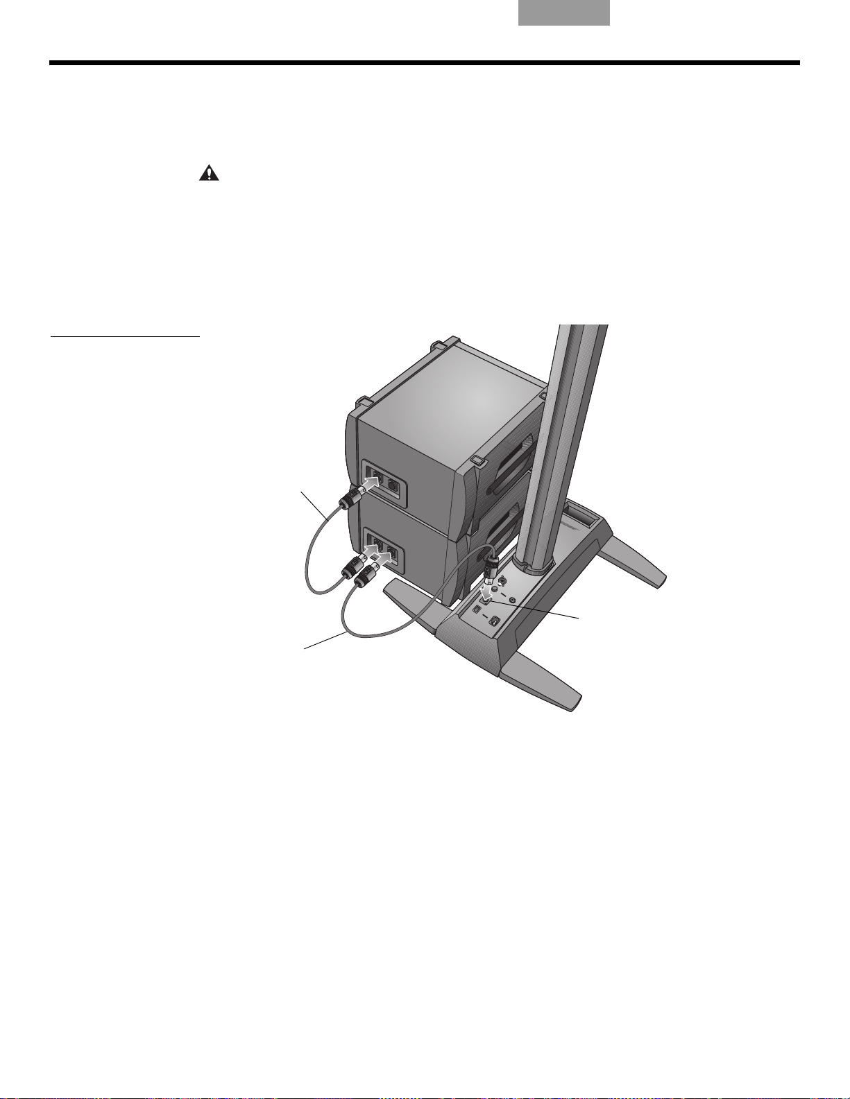
SYSTEM-EINRICHTUNG
Bassmodulkabel
des zweiten B1Moduls
Bassmodulkabel
des ersten
B1-Moduls
Bassmodulausgang
Hinzufügen eines zweiten B1-Bassmoduls (optional)
Über den Bassmodul-Ausgang des Power Stand lassen sich ein oder zwei B1-Bassmodule
betreiben. Bei horizontaler Aufstellung können die Module aufeinandergestapelt werden
(Abbildung 7).
Abbildung 7
Zwei B1 Bassmodule
anschließen
ACHTUNG:
Power Stand an. Wenn Sie mehr als zwei B1-Bassmodule über diesen Ausgang betreiben, wird
der V
erstärker im Power Stand ungleichmäßig belastet, was die Systemleistung beeinträchtigen
kann.
1. Schließen Sie das erste B1-Modul an den Bassmodul-Ausgan
2. Schließen Sie ein Ende des Kabels vom zweiten B1-Modul an den nicht verwendeten
Ansch
Anschlüsse am zweiten B1-Modul.
Schließen Sie höchstens zwei B1 Bassmodule an den Bassmodul-Ausgang am
luss am ersten B1-Modul an. Stecken Sie das andere Ende des Kabels in einen der
g am Po
EnglishDeutschFrançais DanskEspañolItalianoSvenska Nederlands
wer Stand an.
14
Page 55

English Deutsch FrançaisDansk Español Italiano SvenskaNederlands
INFORMATIONEN ZUR BEDIENUNG
Analogen Eingangspegel einstellen
Wenn Sie eine Audioquelle an den analogen Eingang (Analog Input) anschließen, gehen
Sie folgendermaßen vor, um die Tri m-Steuerung zu regulieren.
1.
Stellen Sie den Trim-Regler am Power Stand auf die Null-Position (0).
2. Schließen Sie die Audioquelle an den analogen Eingang (Analog Input) an
3. Stellen Sie die Lautstärke der Audioquelle wie gewünscht ein.
4. Während die Quelle abgespielt wird, erhöhen Sie den Trim-Pe
Signal/Clip grün oder gelb leuchtet.
5. Wenn die Anzeige Signal/Clip rot
Anzeige grün oder gelb leuchtet.
leuchtet, verringern Sie den Trim-Pegel, bis die
Verwenden der T1 ToneMatch®-Audio-Engine und einer analoge
Eingangsquelle
Das L1® Modell 1S-System kann verwendet werden, während sowohl eine T1 ToneMatch®Audio-Engine als auch eine analoge Audioquelle an den Power Stand angeschlossen sind.
Beachten Sie dabei jedoch, dass die Lautstärke der Audio-Engine und der analogen
Audioquelle unabhängig voneinander eingestellt werden.
•Die Tr
• Die T1 ToneMatch-Audio-Engine verfügt über eine Tr
im-Steu
Audioquelle aus, die an den analogen Eingang (Analog Input) angeschlossen ist.
Deshalb zeigt die Anzeige Signal/Clip nur den Status des analogen Eingangssignals an.
zeige für jeden Eingang, einen Lautstärkeregler (Volume) für jeden Ausgangskanal
An
und einen Master-Lautstärkeregler, der den Pegel des ToneMatch-Ausgangs, der an den
Power Stand geleitet wird, regelt. Diese Steuerungen haben keine Auswirkung auf das
Signal, das an den analogen Eingang (Analog Input) geleitet wird.
erung des Power Stand wirkt sich nur auf die Lautstärke der analogen
im-Steuerung und eine Signal/Clip-
gel, bis die Anzeige
.
Aufstellungsbeispiele
Es gibt viele Möglichkeiten, dieses System mit oder ohne T1 ToneMatch-Audio-Engine
aufzubauen und zu verwenden. Auf den folgenden Seiten finden Sie Beispiele für typische
Einsatzmöglichkeiten. Wenn Sie die T1 ToneMatch-Audio-Engine verwenden, informieren Sie
sich in der entsprechenden Bedienungsanleitung über Aufbau und Betrieb der Audio-Engine.
Einzelner Musiker
Ein Solomusiker kann ein einzelnes Instrument über das L1 Modell 1S-System spielen
(Abbildung 1). Ebenso kann ein Solomusiker ein Instrument spielen und ein Mikrofon für den
Gesang verwenden (Abbildung 2 auf Seite 16).
Abbildung 1
Einzelnes System mit
Keyboard
15
Page 56

INFORMATIONEN ZUR BEDIENUNG
T1 ToneMatch®-
Audio-Engine
T1 ToneMatch-
Audio-Engine
Abbildung 2
Einzelnes System mit
Gitarre und Mikrofon
Mehrere Musiker
In diesem Szenario singt und spielt ein Keyboard-Gitarren-Duo über eine T1 ToneMatchAudio-Engine und ein L1
®
-System.
EnglishDeutschFrançais DanskEspañolItalianoSvenska Nederlands
Abbildung 3
Einzelnes System mit
mehreren Instrumenten und
T1 ToneMatch-AudioEngine
16
Page 57

English Deutsch FrançaisDansk Español Italiano SvenskaNederlands
T1 ToneMatch-
Audio-Engine
T1 ToneMatch-
Audio-Engine
T1 ToneMatch-
Audio-Engine
T1 ToneMatch-
Audio-Engine
INFORMATIONEN ZUR BEDIENUNG
Komplette Besetzung
Eine Band mit klassischer Besetzung verwendet mehrere T1 ToneMatch®-Audio-Engines und
®
-Systeme. Jeder Musiker spielt und singt über eine eigene T1 ToneMatch-Audio-Engine
L1
und ein L1-System.
Abbildung 4
Mehrere Systeme mit
jeweils einer T1 ToneMatchAudio-Engine
17
Page 58

INFORMATIONEN ZUR BEDIENUNG
DJ-Events
DJs verwenden viele verschiedenen Eingangsquellen (z. B. CD-Spieler, Plattenspieler,
MP3-Player), die an ein Mischpult angeschlossen sind. In diesem Szenario können zwei
Mischpultausgänge für den Stereoton an zwei L1
Abbildung 5
Zwei Systeme,
ein Mischpult und
Eingang
sgeräte
®
-Systeme angeschlossen werden.
EnglishDeutschFrançais DanskEspañolItalianoSvenska Nederlands
18
Page 59

English Deutsch FrançaisDansk Español Italiano SvenskaNederlands
PFLEGE UND WARTUNG
Pflege des Produkts
Reinigung
• Verwenden Sie zum Reinigen der Gehäuse nur ein weiches, trockenes Tuch.
• Verwenden Sie weder Lösungsmittel oder Chemikalien noch Reinigungsmittel, die Alkohol,
niak oder Polituren enthalten.
Ammo
• Benutzen Sie keine Sprays in der Nähe des Geräts, und achten Sie darauf, dass keine
Flüssig
• Reinigen Sie bei Bedarf das Gitter des L1
Staubsauger.
Kundendienst
Sollten Sie weitere Unterstützung bei der Fehlerbehebung benötigen, wenden Sie sich an
das Bose
+1-877-335-2673 oder besuchen Sie unseren Supportbereich im Internet unter
www.Bose.
Fehlerbehebung
keiten in die Öffnungen gelangen.
®
-Lautsprechers vorsichtig mit einem
®
Live Music Customer Service Product and Technical Support Team unter
com/livesound.
Falls Probleme mit dem Gerät auftreten, beachten Sie die folgenden Lösungsvorschläge.
Lässt sich das Problem dann immer noch nicht lösen, wenden Sie sich direkt an das Bose
Live Music Customer Service Product and Technical Support Team unter der Telefonnummer
+1-877-335-2673, um einen Termin abzusprechen.
Problem Lösung
Das Gerät ist an die
Steckdo
und eingeschaltet, aber die
Power-LED leuchtet nicht
Die Power-LED leuchtet
grü
se angeschlossen
n, aber kein Ton
• Stellen Sie sicher, dass die Steckdose funktioniert und angeschlossen ist. Testen Sie die
St
eckdose, indem Sie eine Lampe oder andere Geräte anschließen, oder verwenden Sie
einen Spannungsprüfer.
• Stellen Sie sicher, dass der Netzstecker des Power Stand vollständig in die Steckdose
e
in
gesteckt ist.
• Stellen Sie sicher, dass der Lautstärkeregler an Ihrem Instrument richtig eingestellt ist.
• Stellen Sie sicher, dass die Trim -St
• Vergewissern Sie sich, dass Ihr Instrument an den analo
angeschlossen ist.
• Schließen Sie das Instrument mit einem anderen Kabel an den Power Stand an.
• Testen Sie das Instrument mit einem anderen Verstärker, um sicherzugehen, dass es
fu
nktion
Empfohlene Werkzeuge zur Problemlösung
• Tragbarer Spannungsmesser • XLR- und ¼"-Klinkensteckerkabel
• Durchgangsprüfer • vieradriges Kabel für B1-Ba
Spannungsprüfer • Ersatz-Netzkabel
•
euerung am Power Stand hochgeregelt ist.
gen Eingang (Analog Input)
iert.
ssmodul
Der Power Stand ist
eingesc
Power-LED leuchtet rot
Die Automaten der
Ha
wiederholt ausgelöst
haltet, die
icherungen werden
uss
• Wenden Sie sich an den Bose Live Music Customer Support unter +1-877-335-2673.
• Falls Sie mehrere Power Stands an denselben Str
Sie die Geräte nicht gleichzeitig, sondern in zeitlichen Abständen nacheinander ein.
Der Einschaltstrom jedes Power Stands liegt bei ca. 32 A.
• Wenn mehr als drei Power Stands an einen 16-A-Str
schließen Sie einen Teil der Geräte an einen anderen Stromkreis an. Jeder der Power
Stands kann bei längerem Betrieb mit hoher Lautstärke 5 A oder mehr aufnehmen.
omkreis anschließen wollen, schalten
omkr
eis angeschlossen sind,
19
Page 60

P
FLEGE UND WARTUNG
Problem Lösung
EnglishDeutschFrançais DanskEspañolItalianoSvenska Nederlands
Wenn nichts an den Power
Stand angeschlossen ist,
ist ein leichtes Brummen
oder Summen zu hören.
Das B1- oder
B
2
-Bassmodul ist
angeschlossen, aber es
werden keine Bässe
wiedergegeben
Die Wiedergabelautstärke
de
s B1-Bas
smoduls ist
unausgewogen bezogen
auf das restliche System
Vom L1
®
-Top-Array sind
keine mittleren/hohen Töne
zu hören
Instrumente oder
Aud
ioquellen hören sich
verzerrt an
• Verwenden Sie einen Spannungsprüfer, um die Steckdose, in die der Power Stand
ges
teckt ist, auf vertauschte oder offene Kontakte zu überprüfen.
• Falls Sie ein Verlängerungskabel verwenden, testen Sie es ebenfalls.
• Vergewissern Sie sich, dass Sie das im Lieferumfang enthaltene vieradrige B1-/B2B
assmodulkabel verwenden.
• Überprüfen Sie, dass das B1- oder B
-Bassmodulkabel an den Anschluss Bass
2
Module Out angeschlossen ist und das Kabel fest im Anschluss sitzt.
• Versuchen Sie es mit einem anderen vieradrigen Kabel.
• Falls möglich, versuchen Sie es mit einem anderen B1-/B2-Bassmodul.
• Stellen Sie sicher, dass das mitgelieferte vieradrige B1-/B2-Bassmodulkabel
ve
rwendet wird.
• Stellen Sie sicher, dass das Abdeckungsgitter des B1- oder B2-Bassmoduls in
Richt
ng der Musiker und des Publikums zeigt.
u
• Vergewissern Sie sich, dass das L1-Top-Array und die unteren Erweiterungen fest in
ihr
en Anschlüssen sitzen.
• Stellen Sie sicher, dass die Stecker nicht verbogen oder abgebrochen sind.
• Säubern Sie die Kontakte des oberen und des unteren Teils des Lautsprechers mit
K
o
ntakt-Reinigungsspray.
• Stellen Sie sicher, dass die Signal/Clip-LED nicht konstant r
ot leuchtet. Falls dies der
Fall ist, reduzieren Sie die Einstellung des Trim-Reglers.
• Probieren Sie eine andere Audioquelle oder ein anderes Instrument aus.
• Probieren Sie die Quelle oder das Instrument mit einem anderen Power Stand aus.
Am Mikrofon treten
Rü
ckko
pplungen auf.
• Richten Sie das Mikrofon so aus, dass es nicht direkt in Richtung des zugehörigen
L1-Systems zeigt.
• Probieren Sie ein anderes Mikrofon aus.
• Verändern Sie die Position des Lautsprech
er
s und/oder des Sängers auf der Bühne.
• Erhöhen Sie den Abstand zwischen dem Lautsprecher und dem Mikrofon.
• Falls Sie einen Effektprozessor verwenden, stellen Sie sicher, dass dieser nicht die
U
sache des Problems ist.
r
20
Page 61

English Deutsch FrançaisDansk Español Italiano SvenskaNederlands
Eingeschränkte Garantie und Registrierung
Für Ihr Produkt gilt eine eingeschränkte Garantie. Einzelheiten zu den Garantiebedingungen
finden Sie im Produktkarton. Sie können das Produkt online unter www.Bose.com/register
oder telefonisch unter der Rufnummer 800-905-1044 (nur in den USA und Kanada)
registrieren. Ihre Garantierechte sind jedoch unabhängig davon gültig.
Zubehör
Informationen zu Zubehör erhalten Sie online unter www.Bose.com/livesound oder
telefonisch unter +1-800-905-0886.
Technische Daten
Mechanische
Komponente Abmessungen Gewicht
Power Stand: 12,8 cm x 26,2 cm x 69,2 cm (HxBxT) 10,7 kg
To p- A rr a y: 111,0 cm x 9,0 cm x 10,5 cm (HxBxT) 7,4 kg
Untere Erweiterungen 100,6 cm x 10,6 cm x 10,5 cm (HxBxT) 3,8 kg
B1-Bassmodul: 38,0 cm x 26,0 cm x 45,0 cm (HxBxT) 11,4 kg
B2-Bassmodul: 59,4 cm x 33,8 cm x 48 cm (HxBxT) 20,41 kg
P
FLEGE UND WARTUNG
Elektronik
• Stromversorgung:
100 - 120 V
• Maximaler Einschaltstrom:
32 A bei 120 V
Komponente Impedanz
®
L1
Model 1S-Lautsprecher: 4 Ω
B1-Bassmodul: 8 Ω
B2-Bassmodul: 4 Ω
50/60 Hz 500 W (USA/Kanada); 220 - 240 V 50/60 Hz 500 W (Europa)
60 Hz (USA/Kanada); 61 A bei 230 V 50 Hz (Europa)
Audio-Ein-/Ausgang
• T1 ToneMatch®-Anschluss: DC-Ausgang/Dateneingang, Ethercon/RJ45-Anschluss für
eine T1 ToneMatch-Audio-Engine
• Analogeingang: Line-Einga
• Bassmodulausgang: Neutrik
L1 und ToneMatch sind eingetragene Marken der Bose Corporation in den USA und anderen Ländern.
Alle Marken sind das Eigentum der jeweilig
en Inhaber.
ngskanal für ¼" TRS-Klinkenstecker
®
NL4-Ausgang für ein oder zwei B1-Bassmodule
21
Page 62

INFORMACIÓN DE SEGURIDAD
Rellene para conservar como referencia
Este puede ser un buen momento para registrar los números de serie del sistema aquí y en la tarjeta de registro
del producto. Puede registrar su producto en línea en www.Bose.com/register o llamando al (800) 905-1044.
No hacerlo no supondrá ningún perjuicio sobre los derechos derivados de la garantía.
Pedestal L1
®
modelo 1S: ________________________________________________________________________
Conjunto superior y extensión inferior: ____________________________________________________________
Módulo de graves B1 o B2: _____________________________________________________________________
Lea esta guía del usuario
Dedique el tiempo que sea necesario para seguir atentamente las instrucciones de esta guía del usuario, que le
ayudarán a configurar y utilizar correctamente el sistema y a disfrutar de todas sus funciones avanzadas.
Guarde esta guía del usuario para utilizarla como m
ADVERTENCIA:
humedad.
Con el fin de reducir el riesgo de descargas eléctricas, no exponga el sistema a la lluvia o la
aterial de
referencia en el futuro.
EnglishDeutschFrançais EspañolEspañolItalianoSvenska Nederlands
ADVERTENCIA:
cualificado. Las reparaciones debe llevarlas a cabo personal cualificado.
El símbolo de relámpago con una flecha dentro de un triángulo equilátero indica al usuario que la caja del
sistema puede contener una tensión sin aislar de magnitud suficiente para constituir un riesgo de descarga
eléc
El signo de exclamación dentro de un triángulo equilátero, tal como aparece marcado en el sistema, avisa al
usuario
PRECAUCIÓN:
protección.
PRECAUCIÓN:
comprometer aspectos de seguridad, cumplimiento normativo y rendimiento del sistema.
PRECAUCIÓN:
PRECAUCIÓN:
accionarse fácilmente.
Nota: Este producto debe utilizarse en espacios interiores. No está diseñado ni se ha probado para uso al aire libre,
en vehículos de recreo o embarcaciones.
Para reducir el riesgo de descargas eléctricas, no desmonte el sistema si no es usted un técnico
trica.
de que existen instrucciones de operación y mantenimiento importantes en esta guía del usuario.
Este producto se debe conectar a una toma de la red eléctrica con una conexión de tierra que sirva de
No realice modificaciones en el sistema o los accesorios. Las alteraciones no autorizadas pueden
No coloque sobre el aparato o cerca de éste llamas vivas, por ejemplo, velas.
Si se utiliza la clavija de red o el conector del aparato como dispositivo de desconexión, deberá poder
Este producto se ajusta a todos los requis
completa en: www.Bose.com/compliance.
©2012 Bose Corporation. Ninguna parte de este trabajo podrá reproducirse, modificarse, distribuirse o usarse de ninguna otra
manera sin permiso previo y por escrito.
2
itos aplicables de la UE. Encontrará la declaración de conformidad
Page 63

English Deutsch FrançaisEspañol Español Italiano SvenskaNederlands
Información sobre productos que
generan ruido eléctrico
NOTA: Este equipo se ha probado y ha quedado
demostrado que cumple con los límites para
dispositivos digitales de clase A, de acuerdo con el
apartado 15 de las normas de la FCC. Estos límites
están diseñados para ofrecer una protección razonable
contra las interferencias perjudiciales cuando el
aparato se utiliza en un entorno comercial. Este equipo
genera, utiliza y puede irradiar energía de
radiofrecuencia y, si no se instala y se utiliza de
acuerdo con el manual de instrucciones, podría
ocasionar interferencias perjudiciales para las
comunicaciones por radio. La utilización de este
equipo en una zona residencial podría causar
interferencias dañinas. En ese caso, la corrección de la
interferencia correrá a cargo del usuario.
Los cambios o modificaciones no aprobados
expresamente por Bose Corporation podrían anular
la autorización que tiene el usuario para utilizar este
equipo.
Este aparato de Clase A cumple las especificación
canadiense ICES-003.
Corriente de irrupción en encendido inicial: 32 Amps
Corriente de irrupción después de 5 segundos de
interrupción de la corriente de red: 32 Amps
Este producto cumple todos los requisitos de
inmunidad EN55103-2 para entornos
electromagnéticos E2.
INSTRUCCIONES DE SEGURIDAD IMPORTANTES
1. Lea las siguientes instrucciones.
2. Guarde estas instrucciones.
3. Tenga presentes todas las advertencias.
4. Siga todas las instrucciones.
5. No utilice este aparato cerca del agua.
6. Límpielo solo con un trapo seco.
7. No bloquee las aberturas de ventilación. Realice
la instalación de acuerdo
del fabricante.
8. No lo instale cerca de fuentes de calor, tales
co
mo radiado
cocinas u otros aparatos (incluidos
amplificadores) que generen calor.
9. No elimine el mecanismo de seguridad del
enc
hufe con toma a tierra o
Los enchufes polarizados disponen de dos
clavijas, una de
Los enchufes con toma a tierra tienen dos
clavij
as y
más ancha y el tercer terminal se incluyen como
medida de seguridad. Si el enchufe
suministrado no encaja en la toma, póngase en
contacto con un electricista para sustituir la
toma antigua.
10. Proteja el cable de alimentación de forma que
nad
cerca de enchufes, receptáculos de tomas
múltiples y en el lugar en que sale del aparato.
11. Utilice solo conexiones y accesorios
sum
12. Utilícelo sólo con el carrito, soporte,
trípode, abrazadera o mesa
suministrados por el fabricante o
incluidos con el dispos
Cuando utilice un carrito, tenga
cuidado
para evitar que caiga y produzca daños.
13. Desenchufe el aparato si se produce una
to
periodos prolongados de tiempo.
14.
Toda reparación debe ser realizada por personal
cualificado.
presenta algún daño, por ejemplo, si el cable de
alimentación o el enchufe están dañados, si se
han vertido líquidos o se han caído objetos
sobre el dispositivo o ha estado expuesto a la
lluvia o humedad, si no funciona correctamente
o ha caído al suelo.
lo pise ni quede pinzado, en particular
ie
inistra
nta eléctrica o si no lo va a utilizar durante
rme
res, salidas de aire caliente,
mayor tamaño que la
un tercer terminal de tierra. La patilla
dos por el fabricante.
al mo
ver el carrito con el dispositivo
Lleve el dispositivo a reparar si
con las instrucciones
polarizado.
otra.
itivo.
15. Para prevenir el riesgo de incendio o descargas
eléct
alargadores o receptáculos de las tomas.
16. Evite que caigan objetos o líquidos sobre el
pr
puntos de niveles de voltaje altos o partes que podrían
sufrir un cortocircuito y causar incendios o descargas
eléctricas.
17. Consulte las indicaciones de seguridad en la
part
18. Utilice fuentes de alimentación adecuadas.
Conect
tal y como se describe en las instrucciones
fun
19. El aparato no debe recibir salpicaduras ni
mojarse, po
contenga líquido, como jarrones, no debe
colocarse sobre éste.
as, evite sobrecargar los enchufes,
ric
oducto, y
e inferio
cionamiento o en el propio producto.
a que podrían entrar en contacto con
r de la caja del producto.
e el producto a una fuente de alimentación,
r lo que cualquier objeto que
de
3
Page 64

EnglishDeutschFrançais EspañolEspañolItalianoSvenska Nederlands
INTRODUCCIÓN 5
Bienvenido . . . . . . . . . . . . . . . . . . . . . . . . . . . . . . . . . . . . . . . . . . . . . . . . . . . . . . . . . . . . . . . . . . . . . . . . . . . . . . . . . . 5
Características y ventajas . . . . . . . . . . . . . . . . . . . . . . . . . . . . . . . . . . . . . . . . . . . . . . . . . . . .
Características del producto . . . . . . . . . . . . . . . . . . . . . . . . . . . . . . . . . . . . . . . . . . . . . . . . . . . .
Conexiones y controles . . . . . . . . . . . . . . . . . . . . . . . . . . . . . . . . . . . . . . . . . . . . . . . . . . . . . .
. . . . . . . . . . . . . . . . . . 5
. . . . . . . . . . . . . . . . 6
. . . . . . . . . . . . . . . . . . 7
INSTALACIÓN DEL SISTEMA 8
Lista de piezas . . . . . . . . . . . . . . . . . . . . . . . . . . . . . . . . . . . . . . . . . . . . . . . . . . . . . . . . . . . . . . . . . . . . . . . . . . . . . . . 8
Colocar el sistema . . . . . . . . . . . . . . . . . . . . . . . . . . . . . . . . . . . . . . . . . . . . . . . . . . . . . . . . .
Instalar el pedestal . . . . . . . . . . . . . . . . . . . . . . . . . . . . . . . . . . . . . . . . . . . . . . . . . . . . . . .
Montar el sistema L1
®
modelo 1S . . . . . . . . . . . . . . . . . . . . . . . . . . . . . . . . . . . . . . . . . . . . . . . . . . . . . . . . . . . . . . . . 10
Conectar a la alimentación de CA . . . . . . . . . . . . . . . . . . . . . . . . . . . . . . . . . . . . . . . . . . . . . . . . . .
Conectar el módulo de graves B1 o B2 . . . . . . . . . . . . . . . . . . . . . . . . . . . . . . . . . . . . . . . . . . . . . . .
Añadir un motor de audio T1 ToneMatch
®
(opcional) . . . . . . . . . . . . . . . . . . . . . . . . . . . . . . . . . . . . . . . . . . . . . . . . . 13
Añadir un segundo módulo de graves B1 (opcional) . . . . . . . . . . . . . . . . . . . . . . . . . . . . . . . . . . . . . . . . . .
. . . . . . . . . . . . . . . . . . . 9
. . . . . . . . . . . . . . . . . . . . . 10
. . . . . . . . . . . . . . 11
. . . . . . . . . . . . . 12
. . . . . . . . 14
INFORMACIÓN OPERATIVA 15
Ajustar el nivel de entrada analógico . . . . . . . . . . . . . . . . . . . . . . . . . . . . . . . . . . . . . . . . . . . . . . . . . . . . . . . . . . . . . . 15
Utilizar un motor de audio T1 ToneMatch
Opciones del usuario . . . . . . . . . . . . . . . . . . . . . . . . . . . . . . . . . . . . . . . . . . . . . . . . . . . . . . . .
Un solo músico . . . . . . . . . . . . . . . . . . . . . . . . . . . . . . . . . . . . . . . . . . . . . . . . . . . . . . . . . . . .
Varios músicos . . . . . . . . . . . . . . . . . . . . . . . . . . . . . . . . . . . . . . . . . . . . . . . . . . . . . . . . . . . .
Banda completa . . . . . . . . . . . . . . . . . . . . . . . . . . . . . . . . . . . . . . . . . . . . . . . . . . . . . . . . . . .
Actuaciones de DJ . . . . . . . . . . . . . . . . . . . . . . . . . . . . . . . . . . . . . . . . . . . . . . . . . . . . . . . . .
®
y una fuente de entrada analógica . . . . . . . . . . . . . . . . . . . . . . . . . . . . . . 15
. . . . . . . . . . . . . . . . . . 15
. . . . . . . . . . . . . . 15
. . . . . . . . . . . . . . 16
. . . . . . . . . . . . . . 17
. . . . . . . . . . . . . . 18
CUIDADO Y MANTENIMIENTO 19
Cuidado del producto . . . . . . . . . . . . . . . . . . . . . . . . . . . . . . . . . . . . . . . . . . . . . . . . . . . . . . . . . . . . . . . . . . . . . . . . . 19
Limpieza . . . . . . . . . . . . . . . . . . . . . . . . . . . . . . . . . . . . . . . . . . . . . . . . . . . . . . . . . . . . .
Cómo solicitar servicio . . . . . . . . . . . . . . . . . . . . . . . . . . . . . . . . . . . . . . . . . . . . . . . . . . . . . .
Resolución de problemas . . . . . . . . . . . . . . . . . . . . . . . . . . . . . . . . . . . . . . . . . . . . . . . . . . . . . .
Garantía limitada y registro . . . . . . . . . . . . . . . . . . . . . . . . . . . . . . . . . . . . . . . . . . . . . . . . . . .
Accesorios . . . . . . . . . . . . . . . . . . . . . . . . . . . . . . . . . . . . . . . . . . . . . . . . . . . . . . . . . . . . .
Información técnica . . . . . . . . . . . . . . . . . . . . . . . . . . . . . . . . . . . . . . . . . . . . . . . . . . . . . . . .
Datos mecánicos . . . . . . . . . . . . . . . . . . . . . . . . . . . . . . . . . . . . . . . . . . . . . . . . . . . . . . . . . .
Datos eléctricos . . . . . . . . . . . . . . . . . . . . . . . . . . . . . . . . . . . . . . . . . . . . . . . . . . . . . . . . .
Entrada y salida de audio . . . . . . . . . . . . . . . . . . . . . . . . . . . . . . . . . . . . . . . . . . . . . . . . . . . . .
. . . . . . . . . . . . . . . . . . 19
. . . . . . . . . . . . . . 19
. . . . . . . . . . . . . . . . 19
. . . . . . . . . . . . . . . . . . 21
. . . . . . . . . . . . . . . . . . . . . 21
. . . . . . . . . . . . . . . . . . . 21
. . . . . . . . . . . . . . 21
. . . . . . . . . . . . . . . . 21
. . . . . . . . . . . . . 21
4
Page 65

English Deutsch FrançaisEspañol Español Italiano SvenskaNederlands
INTRODUCCIÓN
Bienvenido
Gracias por adquirir el sistema Bose® L1® modelo 1S con puerto ToneMatch®. Este sistema,
basado en una nueva y revolucionaria tecnología, aporta las ventajas de un concierto
acústico íntimo a las actuaciones amplificadas.
Esta guía del usuario proporciona instrucciones para la configuración y u
explica cómo conectarle equipos.
Si desea más información sobre el uso de este sistema, incluidas sugerencias, técnicas y
pre
guntas frecuentes, visite www.Bose.com/livesound en Internet.
Características y ventajas
• Usted controla el sonido. Al igual que en una actuación sin amplificar, usted controla el
sonido. Ya no tendrá que preguntarse cómo ha sonado a oídos de sus compañeros o del
público, porque usted oirá lo mismo que ellos.
• I
nstalación fácil y rápida.
cuestión de minutos, lo que le evita el laborioso y a menudo frustrante esfuerzo necesario
para instalar correctamente equipos de sonido convencionales.
• Mejora espe
actuaciones en comparación con el uso de equipos convencionales, porque ya no tendrá
que esforzarse para oír cómo suenan usted y el resto de los músicos.
• Ge
nera entusiasmo y emoción. L
de entusiasmo y emoción que valoran los amantes de la música.
• Usted escucha lo mismo que el público.
que su público, por lo que es menos probable que toquen sus instrumentos a unos niveles
de sonido incómodos.
• La
música suena con un dinamismo natural.
los más intensos se aprecian y disfrutan con claridad.
o del sistema L1 y
s
El sistema L1 es fácil de transportar y se puede instalar en
ular de las actuaciones. Conseguirá mejoras espectaculares en sus
ctac
a mejora en la actuación de los músicos genera el tipo
Por primera vez, los músicos oyen lo mismo
Tanto los fragmentos más suaves como
• Mejora de la presentación. Hay
• Una reproducción de sonido única. El pú
amplificada había disfrutado de la claridad y el entusiasmo que produce escuchar la
reproducción precisa del sonido de cada instrumento y apreciar el sonido de cada
instrumento en su posición sobre el escenario (en lugar de una mezcla mono o incluso
estéreo de todos los instrumentos).
menos objetos en el escenario y, por tanto, más espacio.
blico señala que nunca en una actuación
5
Page 66

I
Conjunto
superior
Pedestal
Sistema L1 modelo 1S con puerto ToneMatch y módulo
de graves B1
Equipos opcionales
Módulo de
graves B1
Motor de audio
T1 ToneMatch
Módulo de
graves B1
adicional
Módulo de
graves B2
Extensión
inferior
NTRODUCCIÓN
Características del producto
El sistema L1® modelo 1S –con puerto ToneMatch® que consiste en: el pedestal, la extensión
inferior, el conjunto superior y un módulo de graves B1 o B2. El sistema también incluye una
bolsa de transporte acolchada para cada uno de sus componentes.
Para ampliar el sistema y mejorar el rendimiento puede añadir:
• Un segundo módulo de graves B1 para bajo, bombo de p
puede alimentar hasta dos módulos de graves B1.
• Un motor de audio T1 ToneMatch para procesamiento de señales digitales, entradas
adicionales y contro
Si desea obtener una lista completa de equipos y accesorios opcionales, visite:
www.Bose.com/livesound.
Figura 1
Sistema L1 modelo 1S y
equipos opcionales
EnglishDeutschFrançais EspañolEspañolItalianoSvenska Nederlands
edal u órgano. Cada pedestal
les de la interfaz de usuario.
6
Page 67

English Deutsch FrançaisEspañol Español Italiano SvenskaNederlands
Interruptor de encendido
Enciende y apaga el sistema.
Red de CA
Conector de entrada
de alimentación de
CA.
Salida del módulo de graves
Señal de salida de graves para
excitar uno o dos módulos de
graves B1. Acepta un cable de
módulo de graves de cuatro hilos.
Regulación
Ajusta el nivel de la señal
de entrada analógica.
Puerto ToneMatch
®
Conexión de alimentación y
audio digital para el motor de
audio T1 ToneMatch
opcional. Acepta el cable
ToneMatch incluido.
Entrada analógica
Una entrada analógica de nivel de
línea. Acepta un cable telefónico
TRS de ¼". Se emplea para un
instrumento u otra fuente de audio.
LED de señal/recorte
Indica el estado de la señal de entrada analógica.
Verde = entrada normal
Amarillo = entrada próxima al recorte
Rojo = recorte de entrada
LED de encendido/fallo
Indica el estado de encendido.
Azul = el sistema está encendido
Rojo = fallo del sistema
Conexiones y controles
Los conectores y controles del sistema se encuentran en el panel superior del pedestal
(Figura 2).
Figura 2
Panel superior del pedestal
I
NTRODUCCIÓN
7
Page 68

Lista de piezas
L1TM Model II System
with ToneMatchTM port
Owner’s Guide
www.Bose.com/musicians
Superior
Parte inferior
B1
Bass Module
Installation Guide
EnglishDeutschFrançais EspañolEspañolItalianoSvenska Nederlands
INSTALACIÓN DEL SISTEMA
El sistema L1® se suministra en tres cajas. Desembale cuidadosamente las cajas y
compruebe que dispone de todos los artículos que se indican en esta página.
ADVERTENCIA:
peligro de asfixia.
Mantenga las bolsas de plástico fuera del alcance de los niños, para evitar el
Caja del pedestal
Pedestal L1
Bolsa de transporte
Cable de alimentación de CA
Guía de instalación Guía del
rápida usuario
Caja del conjunto y
de la extensión
Conjunto superior y extensión inferior
L1 modelo 1S
Bolsa de transporte
Caja del módulo de
graves B1 o B2
Módulo de graves B1 o B2
Cubierta
Cable del módulo de graves
(cuatro hilos)
Almohadillas de goma adhesivas
(sólo para B2)
Tarjeta de registro del producto
Guía del usuario del módulo
de graves B1 o B2
8
Page 69

English Deutsch FrançaisEspañol Español Italiano SvenskaNederlands
Buena
Mejor
Óptima
0,9 m
(3 pies)
1,5 m
(5 pies)
2,1-2,4 m
(7-8 pies)
0,9 m
(3 pies)
0,9 m
(3 pies)
0,9 m
(3 pies)
0,9 m
(3 pies)
1,5 m
(5 pies)
1,5 m
(5 pies)
1,5 m
(5 pies)
1,5 m
(5 pies)
2,1-2,4 m
(7-8 pies)
2,1-2,4 m
(7-8 pies)
2,1-2,4 m
(7-8 pies)
2,1-2,4 m
(7-8 pies)
Colocar el sistema
El emplazamiento del pedestal en el lugar adecuado es un paso importante en la instalación
de este producto.
INSTALACIÓN DEL SISTEMA
Figura 1
Recomendaciones de
ubicación
Determinar la mejor ubicación para la ac
tuación depende de varios aspectos:
• El tamaño del escenario
• El número de artistas
®
• El sistema compartido (añadir un motor de audio T1 ToneMatch
y múltiples
instrumentos)
Las siguientes directrices le ayudarán a realizar una instalación para un concierto o
espect
áculo.
• Instale el sistema en la parte de atrás del escenario donde se realizará la actuación.
• Si es posible, coloque el sistema detrás del artista o artistas.
• Si forma parte de un grupo musical, eviten colocarse muy juntos sobre el escenario. Deje
cierta dista
ncia (lo ideal sería entre 2,1 y 2,4 m) entre usted y el sistema L1
®
y otro artista.
Esto permite que el sonido envuelva a los intérpretes y se refleje en las superficies
adyacentes de la sala, lo que crea un sonido más agradable, que llena la sala.
9
Page 70

INSTALACIÓN DEL SISTEMA
A
B
Toma para
parte inferior
del L1
Conjunto
superior
Extensión
inferior
Bayoneta
Canal
A
B
Frontal del
sistema
Instalar el pedestal
1. Sostenga el pedestal en vertical sobre el suelo (Figura 2A) y sujete una pata y extiéndala
2.
Figura 2
Colocar el pedestal en
el suelo
ADVERTENCIA: NO mueva el sistema completamente montado como una unidad, ya que
podrían producirse daños personales o averías en el producto. Coloque el pedestal en el suelo
en la ub
EnglishDeutschFrançais EspañolEspañolItalianoSvenska Nederlands
todo lo que pueda. Observe que las otras patas se extenderán automáticamente.
Las pa
tas deberán estar totalmente abiertas antes de que pueda conectar la
extensión al pedestal.
Coloque el pedestal en horizontal sobre el suelo en la posición deseada (Figura 2B).
icación elegida antes de montar el sistema.
Montar el sistema L1® modelo 1S
Este procedimiento le indica cómo instalar las secciones del altavoz en el pedestal. Si piensa
montar el motor de audio T1 ToneMatch
motor de audio T1 ToneMatch
superior del altavoz.
1. Sujete la extensión inferior de modo que la cubierta mire hacia delante y conéctela al
Figura 3
Instalar el sistema
pedestal (Fi
estabilidad y una buena conexión.
2. Alinee la bayoneta del conjunto superior con el canal situado al dorso de la parte inferior,
y ba
je la par
gura 3A). Procure insertarla totalmente en el receptáculo para asegurar
te superior sobre la inferior hasta que queden alineadas (Figura 3B).
®
®
(opcional)” en la página 13 antes de instalar la sección
en el sistema L1 modelo 1S, consulte“Añadir un
10
Page 71

English Deutsch FrançaisEspañol Español Italiano SvenskaNederlands
Red de CA
PRECAUCIÓN: NO bloquee
ni cubra la abertura del tirador,
que forma parte del sistema
de ventilación. Si lo hace,
puede provocar el
recalentamiento del sistema
L1
®
, su paso al modo de
protección térmica y su
desconexión temporal.
Interruptor de
encendido
Conectar a la alimentación de CA
1. Compruebe que el interruptor de alimentación se encuentra apagado.
2. Conecte un extremo del cable de alimentación de CA al conector AC Mains del
pedestal.
3.
Enchufe el otro extremo en una toma de red de CA (Figura 4).
Figura 4
Conexiones eléctricas
INSTALACIÓN DEL SISTEMA
PRECAUCIÓN: Bose le recomienda utilizar supresores de sobretensiones de calidad en todos
los equipos electrónicos. Las variaciones y picos de tensión pueden dañar los componentes
electr
ónicos de cualquier sistema. Los supresores de calidad pueden evitar la inmensa mayoría
de las averías atribuibles a las sobretensiones y pueden adquirirse en cualquier tienda de
electrónica.
11
Page 72

INSTALACIÓN DEL SISTEMA
B1
Salida del
módulo de
graves
Salida del
módulo de
graves
B2
Conectar el módulo de graves B1 o B2
Puede ubicar el módulo de graves B1 o B2 en vertical o en horizontal sobre el suelo.
Se ajusta perfectamente entre las patas del pe
1. Conecte un extremo del cable del módulo de graves B1 o B2 a uno de los conectores de
la clavija en el sentido de las agujas del reloj para asegurarla. Cuando quede
Figura 5
Módulos de graves B1 y B2
graves. Gire
bloqueada deberá oírse un “clic” suave.
2. Conecte el otro extremo del cable al conector de salida
pedestal. Gire la clavija en el sentido de las agujas del reloj para asegurarla.
Nota:
Para desconectar un cable B1 o B2, desplace hacia atrás la lengüeta metálica de la
clavija, gire la clavija en el sentido contrario al de las agujas del reloj y sáquela del conector.
destal.
del m
EnglishDeutschFrançais EspañolEspañolItalianoSvenska Nederlands
ódulo de graves del
PRECAUCIONES:
• NO conecte ningún módulo de graves distinto del B1 o del B2 al pedestal.
• NO CAMBIE el cable suministrado por un cable de altavoz de dos hilos. Utilice únicamente
el cable de cu
graves B1 al pedestal. El pedestal utiliza las señales de dos de los hilos para detectar
automáticamente cuántos módulos de graves B1 o B2 están conectados.
• NO conecte un módulo de graves B1 o B2 a dos pedestales al mismo tiempo.
atro hilos del módulo de graves B1 suministrado para conectar el módulo de
12
Page 73

English Deutsch FrançaisEspañol Español Italiano SvenskaNederlands
4
5
6
Carro
Barra de montaje
Extensión inferior
Motor de audio
T1 ToneMatch
1
2
3
Pomo de bloqueo
Pedestal
Correa de gancho y
lazada
Motor de audio
T1 ToneMatch
Extensión
inferior
Cable ToneMatch
(suministrado con T1)
Puerto
ToneMatch
Añadir un motor de audio T1 ToneMatch® (opcional)
El motor de audio T1 ToneMatch® proporciona funciones de entrada/salida adicionales al
sistema, además de procesamiento de señales digitales para personalizar el sonido. El motor
de audio se incluye con hardware para montarlo en lado izquierdo o derecho de la extensión
inferior.
Nota:
El motor de audio se monta en la sección inferior del altavoz y requiere la extracción de la
sección superior antes de comenzar este procedimiento.
1. Deslice el carro dentro del canal situado al dorso de la extensión inferior y gire el pomo
en el
sentido de las agujas del reloj para asegurarlo (Figura 6).
2. Inserte la barra de montaje en la ranura del carro y empújela hacia abajo.
3. Coloque el T1 en la barra de montaje tal como se indica.
4. Conecte un extremo del cable ToneMatch (suministrado con el motor de audio) al puerto
Figura 6
Montaje del T1
de salida
ToneMatch (
5. Empleando la correa de gancho y lazada, fije el cable al carro.
6. Conecte el otro extremo del cable al puerto ToneMatch del pedestal.
) del T1.
INSTALACIÓN DEL SISTEMA
13
Page 74

INSTALACIÓN DEL SISTEMA
Cable del segundo
módulo de graves B1
Cable del primer
módulo de graves B1
Salida del módulo
de graves
Añadir un segundo módulo de graves B1 (opcional)
La salida del módulo de graves del pedestal puede suministrar alimentación a uno o dos
módulos de graves B1. Cuando los módulos se colocan en horizontal, se pueden apilar
(Figura 7).
PRECAUCIÓN:
módulo de graves del pede
B1 desde esta salida, se sobrecargará el amplificador del pedestal y se verá afectado el
rendimiento del sistema.
1. Conecte el primer B1 a la salida de
2. Conecte un extremo del segundo cable B1 al conector no
Conecte el otro extremo del cable a uno de los conectores del segundo B1.
Figura 7
Instalación de los dos
módulos de graves B1
No conecte más de dos módulos de graves B1 al conector de salida del
stal. Si suministra alimentación a más de dos módulos de graves
l módulo de
EnglishDeutschFrançais EspañolEspañolItalianoSvenska Nederlands
graves del pedestal.
utilizado del primer B1.
14
Page 75

English Deutsch FrançaisEspañol Español Italiano SvenskaNederlands
INFORMACIÓN OPERATIVA
Ajustar el nivel de entrada analógico
Cuando conecte una fuente de audio a Analog Input, siga estos pasos para ajustar el
control Trim (regulación) de entrada.
1.
Ajuste el control Trim en el pedestal en posición 0 (cero).
2. Conecte la fuente de audio a Analog Input.
3. Ajus
4. Mientras se reproduce la fuente, aumente el nivel de Trim
5. Si el indicador Signal/C
Utilizar un motor de audio T1 ToneMatch® y una fuente de entrada analógica
El sistema L1® modelo 1S puede funcionar con un motor de audio T1 ToneMatch® y una
fuente de audio analógica conectados al pedestal. Sin embargo, hay que tener en cuenta que
el volumen del motor de audio y el de la fuente de audio analógica se ajustan por separado.
• El control Tr
• El motor de audio T1 ToneMatch tiene un control Tr
te el volumen de la fuente de audio al nivel deseado.
hasta que el indicador
Signal/Clip se ilumine en
ilumine en verde o amarillo.
im del pede
conectada a Analog Input. Por tanto, el indicador Signal/Clip sólo muestra el estado de
la señal de entrada analógica.
cada entrada, un control Volume para cada canal de salida y un control de volumen
Master que ajusta el nivel de la salida de ToneMatch que llega al pedestal. Estos controles
no tienen ningún efecto en la señal que recibe Analog Input.
verde o amarillo.
lip se ilumina en rojo, reduzca el nivel de Trim hasta que se
stal sólo afecta al nivel de volumen de la fuente de audio analógica
n indicador de señal/recorte para
im y u
Opciones del usuario
Existen muchas formas de configurar y utilizar este sistema con y sin el motor de audio T1
ToneMatch. En las páginas siguientes se ofrecen ejemplos de algunos escenarios típicos
para el usuario. Cuando utilice el motor de audio T1 ToneMatch, consulte la información
sobre configuración y funcionamiento que contiene la guía del usuario.
Un solo músico
Un músico individual puede tocar un único instrumento a través del sistema L1 modelo 1S
(Figura 1). Un músico individual también podría tocar un inst
para la voz (Figura 2 en página 16).
Figura 1
Sistema individual con
teclado
rumento y utilizar un micrófono
15
Page 76
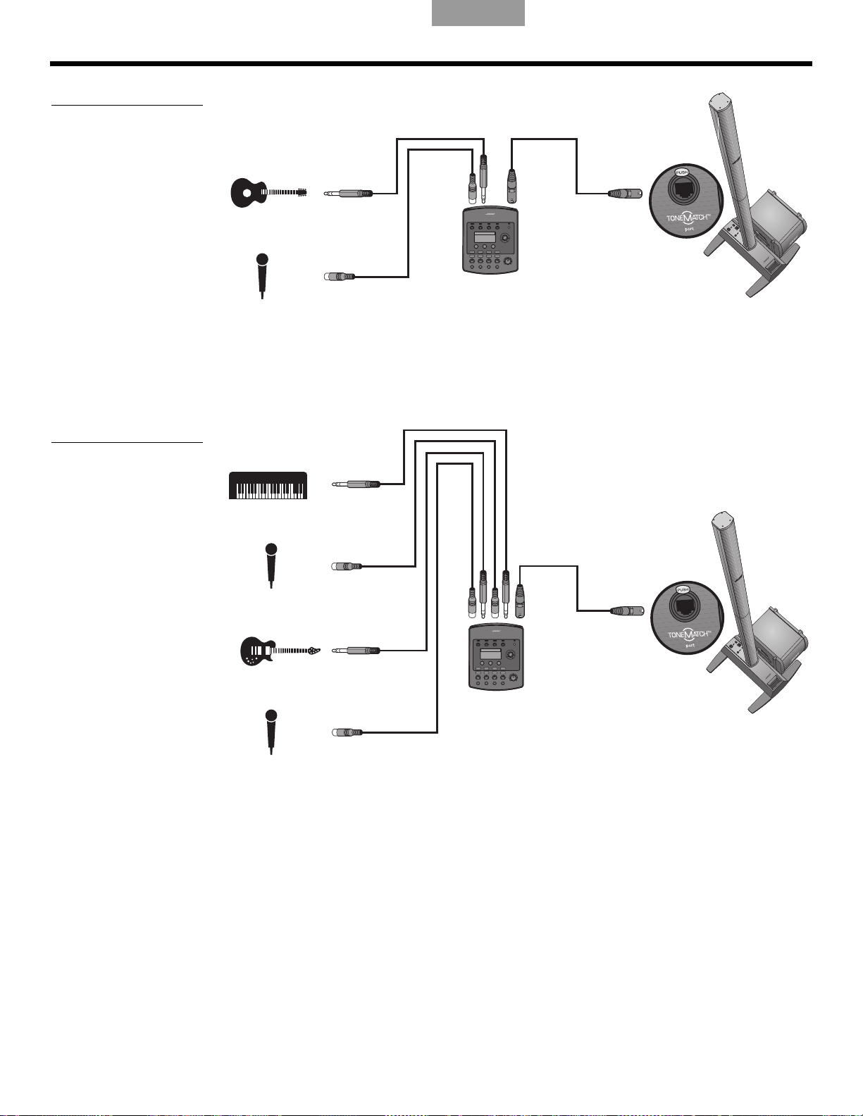
INFORMACIÓN OPERATIVA
Motor de audio
T1 ToneMatch®
Motor de audio
T1 ToneMatch
Figura 2
Sistema individual con
guitarra y micrófono
EnglishDeutschFrançais EspañolEspañolItalianoSvenska Nederlands
Varios músicos
En este escenario, un dúo de teclado-guitarra canta y toca a través de un solo motor de
audio T1 ToneMatch y un sistema L1
®
.
Figura 3
Sistema individual con
varios instrumentos y motor
de audio T1 ToneMatch
16
Page 77

English Deutsch FrançaisEspañol Español Italiano SvenskaNederlands
Motor de audio
T1 ToneMatch
Motor de audio
T1 ToneMatch
Motor de audio
T1 ToneMatch
Motor de audio
T1 ToneMatch
Banda completa
Un escenario de banda completa se establece en torno a varios motores de audio
T1 To ne Ma tc h
T1 ToneMatch individual y un sistema L1.
Figura 4
Varios sistemas, cada uno
con un motor de audio
T1 Ton eM at ch
®
y sistemas L1®. Cada música toca y canta a través de un motor de audio
INFORMACIÓN OPERATIVA
17
Page 78

INFORMACIÓN OPERATIVA
Figura 5
Dos sistemas,
un mezclador y dispositivos
de entrada
EnglishDeutschFrançais EspañolEspañolItalianoSvenska Nederlands
Actuaciones de DJ
Los DJ utilizan muchos tipos de fuentes de entrada (reproductor de CD, plato, reproductor
de MP3, etc.) conectadas a un mezclador. En este escenario, dos salidas del mezclador
pueden introducirse en dos sistemas L1
®
para conseguir sonido estéreo.
18
Page 79

English Deutsch FrançaisEspañol Español Italiano SvenskaNederlands
CUIDADO Y MANTENIMIENTO
Cuidado del producto
Limpieza
• Limpie las superficies del producto empleando un paño suave y seco.
• No use disolventes, sustancias químicas ni detergentes que contengan alcohol, amoníaco
o abrasivos.
No use ningún aerosol cerca del producto ni permit
•
abertura alguna.
• Si es necesario, puede aspirar con cuidado la rejilla
Cómo solicitar servicio
Para obtener ayuda adicional a la hora de resolver problemas, póngase en contacto con el
Equipo de servicio técnico y atención al cliente de música en vivo de Bose
teléfono (877) 335-2673 o visite nuestra área de asistencia técnica en línea en
www.Bose.com/livesound.
Resolución de problemas
a la entrada de ningún líquido por
del altavoz L1
®
®
llamando al
Si tiene algún problema al utilizar este producto, le sugerimos que pruebe las siguientes
soluciones. Si no consigue solucionarlo, llame directamente al Equipo de servicio técnico y
atención al cliente de música en vivo de Bose al (877) 335-2673 para solicitar asistencia.
Herramientas recomendadas para la resolución de problemas
• Voltímetro portátil • Cables con terminación para tel
• Comprobador de cables • Cable de cuatro hilos del módulo de graves B1
• Comprobador de toma de CA • Cable de alimentación de CA de repuesto
Problema Solución
El sistema está enchufado,
terruptor de
el in
alimentación está
encendido, pero el LED de
encendido está apagado
El LED de alimentación
está
encendido (verde),
pero no hay sonido
• Asegúrese de que hay corriente en la toma de CA. Intente enchufar una lámpara u otro
e
quipo eléctrico en la misma toma o compruebe la toma con el probador de tomas
de CA.
• Asegúrese de que la clavija del ca
en la toma de CA.
• Asegúrese de que el control de volum
• Compruebe que el control de regulación se e
• Compruebe que el instrumento está conectado en la entr
• Conecte el instrumento al pedestal con otro diferente.
• Enchufe el instrumento en un amplificador diferente para asegurarse de que funciona
c
ectamente.
orr
éfono XLR y de ¼"
ble de
alimentación del pedestal está bien introducida
en del instrumento musical está alto.
ncuentra en un nivel alto en el pedestal.
ada analógica.
El LED de encendido está
rojo
cuando el pedestal
está encendido
El disyuntor del circuito
domés
c
tico salta
ontinuamente
• Llame al Equipo de atención al cliente de música en vivo de Bose al (877) 335-2673
para solicitar as
• Si tiene más de un pedestal conectado al mismo circuito de CA, ajuste los tiempos de
enc
endido para que no sean simultáneos. Cada pedestal tiene una corriente de
irrupción de unos 32 amperios.
• Si tiene más de tres pedestales enchufados en un único circuito de 15 amperios,
de
splace
algunos sistemas a otro circuito de CA. Cada pedestal puede requerir 5 o más
amperios cuando se reproduce sonido a volúmenes altos durante un cierto tiempo.
istencia.
19
Page 80

C
UIDADO Y MANTENIMIENTO
Problema Solución
EnglishDeutschFrançais EspañolEspañolItalianoSvenska Nederlands
A pesar de que no hay
ningún equipo conectado
al pedestal, se oye un
ligero pitido o zumbido.
El
módulo de graves B1 o
B2
está enchufado, pero
no se oyen los graves
El módulo de graves B1
su
a como si no estuviera
en
balanceado con respecto
al sistema
No se reproducen sonidos
med
ios/altos en el
conjunto superior L1
®
El instrumento o la fuente
de au
dio suenan
distorsionados
• Con un comprobador de toma de CA, pruebe si en la toma de CA a la que se ha
c
onectado el pedestal hay contactos invertidos o abiertos (bajo tensión, neutro y/o
derivado a masa).
• Si utiliza un cable alargador, asegúrese de que
• Compruebe que utiliza el cable del módulo de
comprueba también el cable.
graves B1/B2 de cuatro hilos incluido.
• Compruebe que el cable del módulo de graves B1 o B2 está enchufado al conector
Bass
Module Out y que el enchufe del cable está correctamente insertado en el
conector.
• Pruebe otro cable de cuatro hilos.
• Si es posible, pruebe otro módulo de graves B1/B2.
• Asegúrese de que utiliza el cable de cuatro hilos
del módulo de graves B1/B2 incluido
con dicho módulo.
• Asegúrese de que la rejilla del módulo de graves B
o B2 está orientada hacia los
1
músicos y el público.
• Compruebe que el conjunto superior L1 y la extensión inferior se encuentran
fi
rmemente asentadas en sus conectores.
• Asegúrese de que las conexiones no están dobladas ni rotas.
• Intente limpiar los contactos de las partes superior e inferior del altavoz con un
pu
lve
rizador de limpieza para aparatos electrónicos.
• Compruebe que el LED de señal/recorte no está rojo. Si lo está, baje el nivel de
re
gulación.
• Pruebe con otra fuente o instrumento.
• Pruebe la fuente o el instrumento en otro pedestal.
El micrófono recibe
r
e
alimentación
• Oriente el micrófono de forma que no apunte directamente al sistema L1 correspondiente.
• Pruebe con otro micrófono.
• Coloque el altavoz en otra posición y/o pida al vocalista que se coloque en otro lugar
de
cenario.
l es
• Aumente la distancia del altavoz al micrófono.
• Si utiliza un procesador de efectos
vocales, as
egúrese de que no contribuye al
problema de realimentación.
20
Page 81

English Deutsch FrançaisEspañol Español Italiano SvenskaNederlands
Garantía limitada y registro
Este producto está cubierto por una garantía limitada. Los detalles de la garantía se
suministran con el producto. Registre sus productos en línea en www.Bose.com/register o
llame al (800) 905-1044. No hacerlo no supondrá ningún perjuicio sobre los derechos
derivados de la garantía.
Accesorios
Visite www.Bose.com/livesound o llame al (800) 905-0886 para obtener más información
sobre accesorios.
Información técnica
Datos mecánicos
Vídeo por
componentes Dimensiones Peso
C
UIDADO Y MANTENIMIENTO
Pedestal: 12,8 x 26,2 x 69,2 cm (5 x 10 x 27 pulgadas)
(alto x ancho x fondo)
Conjunto superior: 111,0 x 9,0 x 10,5 cm (43½ x 3½ x 4 pulgadas)
(alto x ancho x fondo)
Extensión inferior: 100,6 x 10,6 x 10,5 cm (39,63 x 4,15 x 4,13 pulgadas)
Módulo de
gr
aves B1:
Módulo de
gr
aves B2:
(alt
38,
(alto x ancho x fondo)
59,
(alto x ancho x fondo)
cho x fondo)
o x an
0 x 26,0 x 45,0 cm (15 x 10¼ x 17¾ pulgadas)
4 x 33,8 x 48 cm (23,4x 13,31 x 18,9 pulgadas)
Datos eléctricos
• Potencia nominal de CA:
100-120 V
• Corriente máxima de irrupción:
a 120 V
32 A
Vídeo por componentes Impedancia
Altavoz L1
Módulo de graves B1: 8 Ω
Módulo de graves B2: 4 Ω
50/60 Hz 500 W (EE UU/Canadá); 220-240 V 50/60 Hz 500 W (Europa)
60 Hz (EE UU/Canadá); 61 A a 230 V 50 Hz (Europa)
®
modelo 1S: 4 Ω
10,7 kg
(23,7 libras
7,4 kg
(16,
3 libras
3,8 kg
(8,5 libras)
11,4 kg
(25,1 libras)
20,41 kg
(45 libras)
)
)
Entrada y salida de audio
• Puerto T1 ToneMatch®: Conector Ethercon/RJ45 de salida CC/entrada de datos
para un motor de audio T1 ToneMatch
• Entrada analógica: Canal de entrada de nivel de línea para conector telefónico
TRS de ¼"
• Salida del módulo de grav
L1 y ToneMatch son marcas comerciales de Bose Corporation registradas en EE UU y otros países.
Las restantes marcas comerciales pertenecen a sus propietarios correspondientes.
es: S
alida Neutrik® NL4 para uno o dos módulos de graves B1
21
Page 82

INFORMATIONS RELATIVES À LA SÉCURITÉ
Renseignements à conserver
Il est recommandé de noter dès maintenant les numéros de série de vos composants, ici et sur votre carte
d’enregistrement. Vous pouvez enregistrer votre produit sur le Web, à la page www.bose.com/register, ou par
téléphone en appelant le (800) 905-1044 (USA et Canada uniquement). En cas d’oubli, les droits que vous
confère cette garantie limitée ne s’en trouveront pas affectés.
Socle amplificateur L1
®
modèle 1S : ______________________________________________________________
Array supérieure et extension inférieure : __________________________________________________________
Module de basses B1 ou B2 : ___________________________________________________________________
Veuillez lire cette notice d’utilisation
Prenez le temps de lire attentivement les instructions de cette notice d’utilisation. Elles vous seront précieuses pour
installer et utiliser correctement votre système et vous aideront à tirer le meilleur parti de sa technologie. Conservez
cette notice d’utilisation pour référence ultérieure.
AVERTISSEMENT :
l’humidité.
Afin de limiter les risques d’incendie ou d’électrocution, n’exposez pas l’appareil à la pluie ou à
EnglishFrançaisFrançais DanskEspañolItalianoSvenska Nederlands
AVERTISSEMENT :
qualifications requises. Adressez-vous à un réparateur qualifié.
Le symbole représentant un éclair avec une flèche à l’intérieur d’un triangle équilatéral est utilisé pour
prévenir l’utilisateur de la présence d’une tension électrique dangereuse non isolée à l’intérieur de l’appare
Cette tension est d’un niveau suffisamment élevé pour représenter un risque d’électrocution.
Le symbole représentant un point d’exclamation à l’intérieur d’un triangle équilatéral, tel qu’il fi
système, signale à l’utilisateur la présence d’instructions importantes relatives au fonctionnement et à
l’entretien de l’appareil dans cette notice d’installation.
ATTENTION :
ATTENTION :
compromettre votre sécurité, le respect des réglementations et les performances.
ATTENTION :
ATTENTION :
l’appareil, elle doit rester facilement accessible.
Remarque : Ce produit doit être utilisé à l’intérieur. Il n’a pas été conçu ni testé pour une utilisation en extérieur, dans
des véhicules ou sur des bateaux.
Afin de limiter les risques d’électrocution, ne démontez pas ce système à moins de disposer des
gure sur le
Cet appareil doit être connecté à une prise électrique dotée d’une mise à la terre.
N’apportez aucune modification au système ou aux accessoires. Toute modification non autorisée peut
Ne placez jamais d’objets enflammés, tels que des bougies allumées, sur l’appareil.
Lorsque la fiche d’alimentation ou la prise multiple est utilisée comme dispositif de débranchement de
il.
Ce prod
complète de conformité est disponible à l’adresse www.bose.com/compliance.
©2012 Bose Corporation. Toute reproduction, modification, distribution ou autre utilisation, même partielle, de ce document est
interdite sans autorisation écrite préalable.
2
uit est conforme à toutes les directives de la Communauté Européenne qui s’y appliquent. L’attestation
Page 83

English Français FrançaisDansk Español Italiano SvenskaNederlands
Informations sur les produits
générateurs de bruit électrique
Remarque : ce matériel a fait l’objet de tests prouvant
sa conformité aux limites imposées aux appareils
numériques de classe A, conformément à la partie 15
des réglementations de la FCC. Ces limites sont
conçues pour offrir une protection raisonnable contre
les interférences nuisibles lorsque l’appareil est utilisé
en environnement commercial. Ce matériel génère,
utilise et est susceptible d’émettre de l’énergie à
fréquence radio. À ce titre, s’il n’est pas installé ou
utilisé conformément aux instructions, il est
susceptible de perturber les communications radio.
L’utilisation de cet équipement dans une zone
résidentielle risque de provoquer des interférences
nuisibles, auquel cas l’utilisateur devra remédier au
problème à ses propres frais.
Toute modification non autorisée expressément par
Bose Corporation est susceptible d’annuler le droit de
l’utilisateur à mettre en œuvre celui-ci.
Ce produit de classe A est conforme aux spécifications
de la réglementation ICES-003 du Canada.
Courant d’appel à la mise sous tension : 32 A
Courant d’appel après une coupure d’alimentation de
5 secondes : 32 A
Ce produit répond aux critères d’immunité des
directives EN55103-2 pour les appareils de classe E2.
INSTRUCTIONS IMPORTANTES RELATIVES À LA SÉCURITÉ
1. Veuillez lire ces instructions.
2. Veuillez conserver ces instructions.
3. Respectez tous les avertissements.
4. Suivez toutes les instructions.
5. N’utilisez pas cet appareil à proximité d’eau ou
d’une source
6. Utilisez uniquement un chiffon sec pour le
nettoyage.
7. Ne bl
8. N’installe
9. Veillez à profiter de la sécurité offerte par les
10. Protégez le cordon d’alimentation contre les
11. Utilisez uniquement les ac
12. Utilisez uniquement le chariot,
13. Débranchez cet appareil pendant les orages ou
14.
oquez jamais les orifices d’aération.
Suivez les instructions du fabricant pour
l’i
nstallation.
quelconque sour
radiateur, une arrivée d’air chaud, un four ou
tout autre appareil (notamment des
amplificateurs) produisant de la chaleur.
f
es de type terre ou polarisées. Les fiches
ich
polarisées sont équipées de deux bornes de
largeurs différentes. Les fiches de type terre
sont équipées de deux bornes et d’un orifice
pour la mise à la terre. Ces deux types de
dispositifs ont pour but d’assurer votre sécurité.
Si la fiche fournie ne s’adapte pas à votre prise
de courant, consultez un électricien pour qu’il
remplace cette prise obsolète.
risque
notamment au niveau des fiches, des prises de
courant et des branchements à l’appareil.
par le fabricant.
le support, le trépied,
table spécifié(e) par le fabricant ou
vendu(e) avec l’appar
utilisez un chariot, faites attention à
ne pas faire basculer l’ensemble chariot/
appareil.
au cour
utilisation.
Confiez toute réparation à du personnel qualifié.
Une réparation est nécessaire lorsque l’appareil
a été endommagé de quelque façon que ce soit
(endommagement du cordon d’alimentation ou
de la fiche électrique, renversement d’un
liquide ou de tout objet sur l’appareil, exposition
de l’appareil à la pluie ou à l’humidité, mauvais
fonctionnement, chute de l’appareil, etc.).
s de piét
d’humidité.
z pas cet appareil à proximité d’une
ce de chaleur, telle qu’un
inement ou de pincement,
ce
ssoires spécifiés
l’équerre ou la
eil. Si vous
s longues périodes de non
s de
15. Pour éviter tout risque d’incendie ou
d’électr
murales, les rallonges ou les prises multiples.
16. Ne laissez jamais d’eau ou d’objets pénétrer à
l’inté
pourraient être touchés ou il pourrait se produire un
court-circuit susceptible d’entraîner un incendie ou un
risque d’électrocution.
17. Consultez les marquages de séc
boîtier du produit.
18. Utilisez des sources d’alimentation
app
d’aliment
instructions relatives au fonctionnement ou signalé sur
le produit.
19. Protégez l’appareil de tout risque de
ruiss
d’objets contenant des liquides, tels que des
vases, sur l’appareil.
oc
ution, ne surchargez pas les prises
rieur du
ropriées – Branchez le produit sur une source
ellement
produit : des éléments sous tension
sous le
urité
ation appropriée, comme indiqué dans les
ou d’éclaboussure. Ne placez pas
3
Page 84

EnglishFrançaisFrançais DanskEspañolItalianoSvenska Nederlands
INTRODUCTION 5
Bienvenue . . . . . . . . . . . . . . . . . . . . . . . . . . . . . . . . . . . . . . . . . . . . . . . . . . . . . . . . . . . . . . . . . . . . . . . . . . . . . . . . . . 5
Caractéristiques et avantages . . . . . . . . . . . . . . . . . . . . . . . . . . . . . . . . . . . . . . . . . . . . . . . . . . .
Présentation . . . . . . . . . . . . . . . . . . . . . . . . . . . . . . . . . . . . . . . . . . . . . . . . . . . . . . . . . . . .
Connexions et réglages . . . . . . . . . . . . . . . . . . . . . . . . . . . . . . . . . . . . . . . . . . . . . . . . . . . . . .
. . . . . . . . . . . . . . . . 5
. . . . . . . . . . . . . . . . . . . . . 6
. . . . . . . . . . . . . . . . . . 7
CONFIGURATION DU SYSTÈME 8
Nomenclature . . . . . . . . . . . . . . . . . . . . . . . . . . . . . . . . . . . . . . . . . . . . . . . . . . . . . . . . . . . . . . . . . . . . . . . . . . . . . . . . 8
Positionnement de votre système . . . . . . . . . . . . . . . . . . . . . . . . . . . . . . . . . . . . . . . . . . . . . . . . . .
Installation du socle amplificateur . . . . . . . . . . . . . . . . . . . . . . . . . . . . . . . . . . . . . . . . . . . . . . . .
Assemblage du système L1
®
modèle 1S . . . . . . . . . . . . . . . . . . . . . . . . . . . . . . . . . . . . . . . . . . . . . . . . . . . . . . . . . . . 10
Connexion au secteur . . . . . . . . . . . . . . . . . . . . . . . . . . . . . . . . . . . . . . . . . . . . . . . . . . . . . . .
Connexion du module de basses B1 ou B2 . . . . . . . . . . . . . . . . . . . . . . . . . . . . . . . . . . . . . . . . . . . . . .
Ajout d’un moteur audio T1 ToneMatch
®
(facultatif) . . . . . . . . . . . . . . . . . . . . . . . . . . . . . . . . . . . . . . . . . . . . . . . . . . 13
Ajout d’un second module de basses B1 (facultatif) . . . . . . . . . . . . . . . . . . . . . . . . . . . . . . . . . . . . . . . .
. . . . . . . . . . . . . . 9
. . . . . . . . . . . . . . . . 10
. . . . . . . . . . . . . . . . . . 11
. . . . . . . . . . 12
. . . . . . . . . . 14
INFORMATIONS D’UTILISATION 15
Réglage du niveau d’entrée analogique . . . . . . . . . . . . . . . . . . . . . . . . . . . . . . . . . . . . . . . . . . . . . . . . . . . . . . . . . . . . 15
Utilisation d’un moteur audio T1 ToneMatch
Exemples d’utilisation . . . . . . . . . . . . . . . . . . . . . . . . . . . . . . . . . . . . . . . . . . . . . . . . . . . . . .
Musicien seul . . . . . . . . . . . . . . . . . . . . . . . . . . . . . . . . . . . . . . . . . . . . . . . . . . . . . . . . . . .
Plusieurs musiciens . . . . . . . . . . . . . . . . . . . . . . . . . . . . . . . . . . . . . . . . . . . . . . . . . . . . . . . .
Orchestre . . . . . . . . . . . . . . . . . . . . . . . . . . . . . . . . . . . . . . . . . . . . . . . . . . . . . . . . . . . .
Disc Jockey . . . . . . . . . . . . . . . . . . . . . . . . . . . . . . . . . . . . . . . . . . . . . . . . . . . . . . . . . . . .
®
et d’une source audio analogique . . . . . . . . . . . . . . . . . . . . . . . . . . . . 15
. . . . . . . . . . . . . . . . . . . 15
. . . . . . . . . . . . . . . . 15
. . . . . . . . . . . . . . 16
. . . . . . . . . . . . . . . . . . 17
. . . . . . . . . . . . . . . . 18
ENTRETIEN 19
Entretien du produit . . . . . . . . . . . . . . . . . . . . . . . . . . . . . . . . . . . . . . . . . . . . . . . . . . . . . . . . . . . . . . . . . . . . . . . . . . . 19
Nettoyage . . . . . . . . . . . . . . . . . . . . . . . . . . . . . . . . . . . . . . . . . . . . . . . . . . . . . . . . . . . . . .
Service après-vente . . . . . . . . . . . . . . . . . . . . . . . . . . . . . . . . . . . . . . . . . . . . . . . . . . . . . . . .
Résolution des problèmes . . . . . . . . . . . . . . . . . . . . . . . . . . . . . . . . . . . . . . . . . . . . . . . . . . . . . .
Garantie limitée et enregistrement . . . . . . . . . . . . . . . . . . . . . . . . . . . . . . . . . . . . . . . . . . . . . . . . . .
Accessoires . . . . . . . . . . . . . . . . . . . . . . . . . . . . . . . . . . . . . . . . . . . . . . . . . . . . . . . . . . . .
Informations techniques . . . . . . . . . . . . . . . . . . . . . . . . . . . . . . . . . . . . . . . . . . . . . . . . . . . . . .
Spécifications mécaniques . . . . . . . . . . . . . . . . . . . . . . . . . . . . . . . . . . . . . . . . . . . . . . . . . . . . .
Spécifications électriques . . . . . . . . . . . . . . . . . . . . . . . . . . . . . . . . . . . . . . . . . . . . . . . . . . . .
Entrées et sorties audio . . . . . . . . . . . . . . . . . . . . . . . . . . . . . . . . . . . . . . . . . . . . . . . . . . . . .
. . . . . . . . . . . . . . . . 19
. . . . . . . . . . . . . . 19
. . . . . . . . . . . . . . . . 19
. . . . . . . . . . . . . . 21
. . . . . . . . . . . . . . . . . . . . . 21
. . . . . . . . . . . . . . . . . . 21
. . . . . . . . . . . 21
. . . . . . . . . . . . . 21
. . . . . . . . . . . . . . 21
4
Page 85

English Français FrançaisDansk Español Italiano SvenskaNederlands
INTRODUCTION
Bienvenue
Merci d’avoir choisi le système Bose® L1® modèle 1S avec connecteur pour port ToneMatch®.
Ce système est le fruit d’une nouvelle technologie révolutionnaire et permet de bénéficier de
la qualité d’un concert acoustique intimiste tout en profitant des performances de
l’amplification.
Cette notice technique conti
votre système L1.
e
nt les instructions d’installation, de connexion et d’utilisation de
Pour plus d’informations sur l’utilisation de ce s
fréquentes), visitez le site Internet www.bose.com/livesound.
Caractéristiques et avantages
• Vous contrôlez le son : comme lors d’un concert non amplifié, vous seul contrôlez le son.
Vous n’avez plus de doutes sur la qualité du son perçu par les autres musiciens ou par vos
auditeurs, car vous entendez ce qu’ils entendent.
• I
nstallation simple et rapide :
en quelques minutes, et non en plusieurs heures. Vous êtes enfin libéré des efforts longs,
épuisants et frustrants requis pour installer correctement des équipements sonores
conventionnels.
• Améliora
s’accroissent considérablement, car vous n’avez plus à vous démener pour vous entendre
ou entendre les autres musiciens.
• Une sour
suscite le plaisir et l’émotion que recherchent les mélomanes.
• Vous entendez ce que le public entend : pour
ce qu’entend leur public et ne risquent plus de jouer à des niveaux sonores désagréables.
• La musique est naturellement dynamique : il est désorm
d’apprécier les passages les plus doux comme les parties les plus intenses.
• Un meilleur aspect visuel
• Une reproduction acoustique inégalée :
dégagent de la reproduction fidèle du son de chaque instrument et du respect de la
position de chacun d’eux sur la scène (contrairement au mixage mono ou même stéréo de
tous les instruments) est sans commune mesure avec les performances amplifiées qu’ils
ont eu l’occasion d’écouter auparavant.
tion c
de plaisir et d’émotion : l’amélioration des performances des musiciens
ce
ystème (conseils, techniques et questions
le système L1 est facile à transporter et peut être installé
onsidérable des performances : les performances et le plaisir
la première fois, les musiciens entendent
ais possible d’entendre et
: il y a moins de matériel sur scène et davantage d’espace.
selon le public, la clarté et le plaisir qui se
5
Page 86

I
Array
supérieure
Socle
amplificateur
Système L1 modèle 1S avec connecteur ToneMatch et
module de basses B1
Équipements optionnels
Module de
graves B1
Moteur audio
T1 ToneMatch
Module de graves
B1 supplémentaire
Module de
basses B2
Extension
inférieure
NTRODUCTION
Présentation
Figure 1
Système L1 modèle 1S et
équipement facultatif
EnglishFrançaisFrançais DanskEspañolItalianoSvenska Nederlands
Le système L1® modèle 1S avec port pour ToneMatch® est composé du socle amplificateur,
de l’extension inférieure, de l’array supérieure et d’un module de graves B1 ou B2. Un sac de
transport rembourré accueille tous les éléments du système L1.
Pour améliorer plus encore les performances du système, vous pouvez lui ajouter :
• Un second module de graves B1 pour une guitare basse, une grosse caisse ou un orgue.
Chaque
socle amplificateur peut alimenter jusqu’à deux modules de graves B1.
• Un moteur audio T1 ToneMatch pour traitement numérique du signal, et apportant des
entrées suppélmentair
es et une interface utilisateur.
Vous trouverez une liste complète des équipements et accessoires complémentaires sur le
site We
b www.bose.com/livesound.
6
Page 87

English Français FrançaisDansk Español Italiano SvenskaNederlands
Interrupteur marche/arrêt
Mise en service ou arrêt du système.
Prise secteur
Connecteur du cordon
d’alimentation secteur.
Sortie du module de graves
Signal de sortie des graves pour
alimenter un ou deux modules de
graves B1. Accepte un câble à 4
conducteurs pour module de graves
Écrêtage
Réglage de niveau du signal
d’entrée analogique.
Port ToneMatch
®
Connexion audio numérique
et secteur pour le moteur
audio T1 ToneMatch
facultatif. Reçoit le câble
ToneMatch fourni.
Entrée analogique
Entrée analogique de niveau
ligne. Accepte un câble
TRS ¼". Permet de connecter
un instrument ou une autre
source audio.
Diode Signal/Écrêtage
Indique l’état du signal d’entrée analogique.
Vert = niveau d’entrée normal
Jaune = niveau d’entrée en limite d’écrêtage
Rouge = écrêtage
Diode secteur/défaillance
Indique l’état du système.
Bleu = en service
Rouge = défaillance
Connexions et réglages
Les connecteurs et les commandes sont situés sur le panneau supérieur du socle
amplificateur (Figure 2).
Figure 2
Panneau supérieur du socle
amplificateur
I
NTRODUCTION
7
Page 88

CONFIGURATION DU SYSTÈME
L1TM Model II System
with ToneMatchTM port
Owner’s Guide
www.Bose.com/musicians
Haut
Bas
B1
Bass Module
Installation Guide
Nomenclature
Le système L1® est fourni dans trois cartons. Déballez les éléments avec précaution et
vérifiez la présence de tous les composants indiqués sur cette page.
AVERTISSEMENT :
portée des enfants.
Carton du socle amplificateur Carton de l’arrêt et de l’extension
Pour éviter tout risque d’étouffement, gardez les sacs plastiques hors de
EnglishFrançaisFrançais DanskEspañolItalianoSvenska Nederlands
Carton du module de basses B1
ou B2
Socle amplificateur L1
Sac de transport
cordon d’alimentation
Guide d’installation Notice
rapide d’utilisation
Array supérieure et extension
inférieure de l’enceinte L1 modèle S
Sac de transport
Module de basses B1 ou B2
Capot
Câble pour module de basses (4 fils)
Pieds en caoutchouc
(pour B2 uniquement)
Carte d’enregistrement
Notice d’utilisation du module de
basses B1 ou B2
8
Page 89

English Français FrançaisDansk Español Italiano SvenskaNederlands
Bonne
Bon
Idéal
0,9 m
1,5 m
2,1-2,4 m
0,9 m 0,9 m
0,9 m0,9 m
1,5 m1,5 m
1,5 m 1,5 m
2,1-2,4 m
2,1-2,4 m
2,1-2,4 m 2,1-2,4 m
CONFIGURATION DU SYSTÈME
Positionnement de votre système
Le positionnement du socle amplificateur est une phase importante de l’installation de ce
produit.
Figure 1
Conseils de positionnement
L’identification du meilleur emplacement dépend de plusieurs paramètres
:
• la taille de la scène,
• le nombre de musiciens,
®
• les systèmes partagés (ajout d’un moteur audio T1 ToneMatch
et de plusieurs
instruments).
Les instructions suivantes vous permettront de commencer l’installation en vue d’un concert
ou d’un
spectacle.
• Installez le système dans le volume arrière de la scène.
• Si possible, placez le système derrière le ou les musiciens.
• Si vous êtes membre d’un groupe, évitez de vous serrer sur la scène. Laissez une
e distance (idéalement de 2,1 à 2,4 mètres) entre le système L1
certain
®
et vous ou tout
autre musicien. De cette façon, le son entoure les musiciens et se réfléchit sur les
surfaces adjacentes de la salle, créant un son panoramique qui envahit toute la pièce
et suscite un plus grand plaisir d’écoute.
9
Page 90

CONFIGURATION DU SYSTÈME
A
B
Logement
pour la
base du L1
Array
supérieure
Extension
inférieure
Baïonnette
Canal
A
B
Avant du
système
Installation du socle amplificateur
1. Tout en maintenant le socle amplificateur verticalement au sol (Figure 2A), saisissez l’un
des pieds et écartez-le le plus possible. Les autres pieds se déplient automatiquement.
Les pi
eds doivent être entièrement déployés pour qu’il soit possible
d’emboîter l’extension dans le socle amplificateur.
2. Posez le socle amplificateur à plat sur le
Figure 2
Pose du socle amplificateur
sur le sol
AVERTISSEMENT : NE DÉPLACEZ JAMAIS le système entièrement assemblé. Vous pourriez
vous blesser ou endommager le produit. Positionnez le socle amplificateur sur le sol à
l’empl
acement choisi avant d’assembler le système.
l dans la position désirée (Figure 2B).
so
EnglishFrançaisFrançais DanskEspañolItalianoSvenska Nederlands
Assemblage du système L1® modèle 1S
Cette procédure décrit l’installation des sections de l’enceinte dans le socle amplificateur.
Figure 3
Installation du système
Pour monter le moteur audio T1 ToneMatch
moteur audio T1 ToneMatch
de l’enceinte.
1. Présentez l’extension inférieure avec le capot orienté vers l’avant et emboîtez-la dans le
socle amplific
ateur (Figure 3A). Veillez à l’insérer en entier dans le logement pour
sa stabilité et la qualité de la connexion.
2. Align
ez la baïonnette de l’array supérieure sur la cannelure à l’arrière de la base,
et abaissez l’array sur la partie inférieure pour l’emboîter (Figure 3B).
®
(facultatif) » à la page 13 avant d’installer la section supérieure
®
sur le système L1 modèle 1S, voir « Ajout d’un
assurer
10
Page 91

English Français FrançaisDansk Español Italiano SvenskaNederlands
Prise secteur
ATTENTION : Veillez à NE
PAS bloquer ou couvrir
l’ouverture de la poignée, elle
fait partie du système de
ventilation. Vous pourriez
provoquer une surchauffe du
système L1
®
modèle II, ce qui
déclencherait la protection
thermique et éteindrait
l’appareil.
Interrupteur
marche/arrêt
CONFIGURATION DU SYSTÈME
Connexion au secteur
1. Vérifiez que le commutateur de mise sous tension est en position coupée (OFF).
2. Connectez le cordon d’alimentation à la prise AC Ma
3. Branchez l’autre extrémité à une prise secteur (Figure 4).
Figure 4
Connexions secteur
ins du socle amplificateur.
ATTENTION : Bose recommande de protéger tous les équipements électroniques par un
dispositif de protection contre les surtensions. Les variations de
tension et les surcharges
transitoires peuvent endommager les composants de n’importe quel système. Des dispositifs de
protection contre les surtensions sont disponibles dans les magasins spécialisés en électronique.
11
Page 92
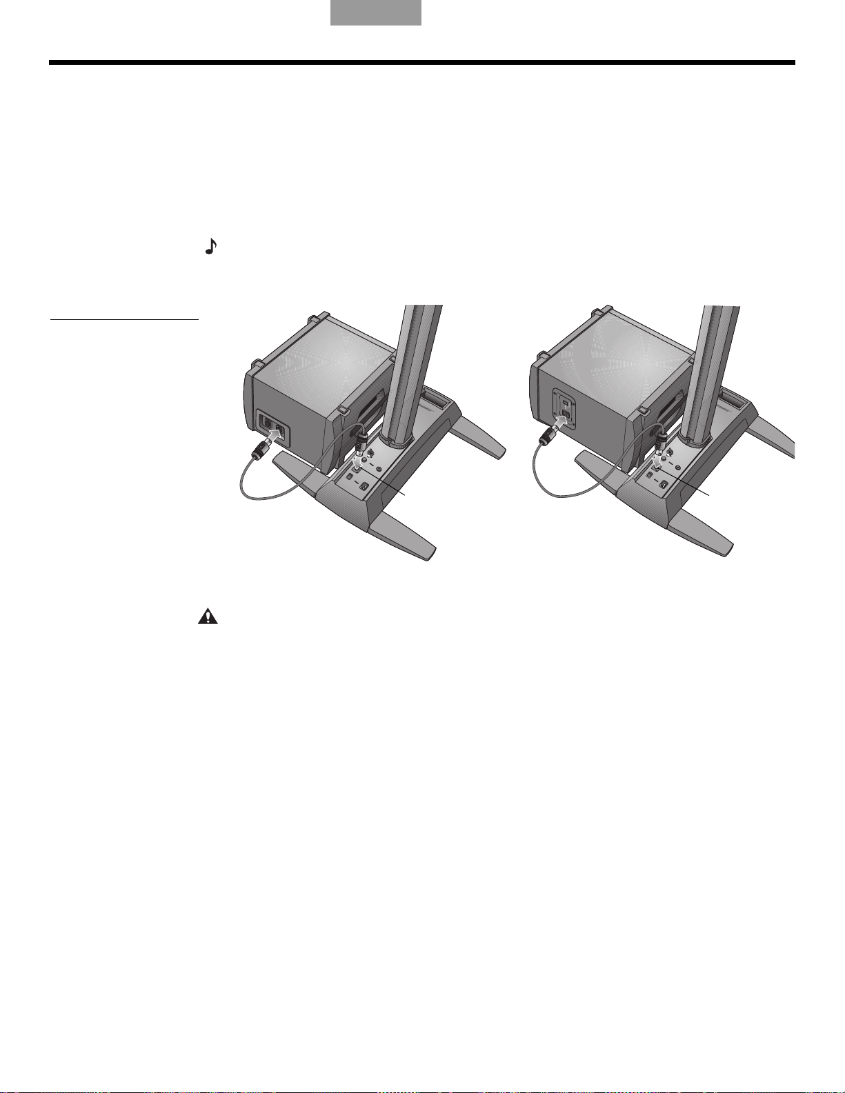
CONFIGURATION DU SYSTÈME
B1
Sortie du module
de graves
Sortie du
module de
graves
B2
Connexion du module de basses B1 ou B2
Le module de graves B1 ou B2 peut être placé sur le sol verticalement ou horizontalement.
Il s’adapte entre les pieds du socle amplificateur.
1. Branchez une extrémité du câble du module de basses B1 ou B2 dans l’un des
Figure 5
Modules de basses B1
et B2
connecteurs de bass
Vous devez entendre un déclic.
2. Insérez l’autre extrémité du câble dans le connecteur Bass Module
amplificateur. Verrouillez la fiche en la faisant tourner dans le sens horaire.
Remarque :
métal situé sur le corps de la fiche, faites tourner celle-ci dans le sens inverse
montre et retirez-la du connecteur.
Pour déconnecter un câble B1 ou B2, faites glisser vers l’arrière le poussoir en
es. Verrouillez la fiche en la faisant tourner dans le sens horaire.
EnglishFrançaisFrançais DanskEspañolItalianoSvenska Nederlands
Out du so
des aiguilles d’une
cle
ATTENTION
• NE PAS connecter au socle amplificateur un module de basses autre que le module B1
ou B2.
• NE PAS remplacer le câble fourni par un câble d’enceinte à 2 fils. Utiliser uniquement l
câble à quatre broches pour module de basses B1 fourni pour connecter le module B1 au
socle amplificateur. Le socle amplificateur utilise les signaux transmis par deux des quatre
fils du câble pour détecter automatiquement le nombre de modules de basses B1 ou B2
connectés.
• NE PAS connecter un module de basses B1 ou B2 à deux socles amplificateurs en
mê
me temp
e
s.
12
Page 93

English Français FrançaisDansk Español Italiano SvenskaNederlands
4
5
6
Support
Barre de montage
Extension inférieure
Moteur audio
T1 ToneMatch
1
2
3
Molette de verrouillage
Socle
amplificateur
Crochet et collier
Moteur audio
T1 ToneMatch
Extension
inférieure
Câble du ToneMatch
(fourni avec le T1)
Port du
ToneMatch
CONFIGURATION DU SYSTÈME
Ajout d’un moteur audio T1 ToneMatch® (facultatif)
Le moteur audio T1 ToneMatch® offre des capacités d’entrées/sorties supplémentaires et son
traitement numérique du signal permet de modifier le son produit. Le moteur audio est fourni
avec des accessoires de montage pour l’adapter du côté gauche ou droit de l’extension
inférieure.
Remarque :
préalable de la section supérieure.
Il se monte sur la section inférieure de l’enceinte, ce qui nécessite une dépose
Figure 6
Montage du T1
1. Faites glisser le support dans la glissière à l’arrièr
e de l’extension inférieure et tournez le
bouton dans le sens des aiguilles d’une montre pour verrouiller le support (Figure 6).
2. Insérez la barre de montage dans son logement dans le
3. Placez le T1 sur la barre de montage comme s
ur l’illustration.
support et poussez-la vers le bas.
4. Branchez une extrémité du câble du ToneMatch (fourni avec le moteur audio) dans le
conn
ecteur de sortie pour le ToneMatch (
5. Fixez le câble sur le support à l’aide du crochet et du collier
) sur le T1.
.
6. Insérez l’autre extrémité du câble dans le connecteur ToneMatch du socle amplificateur.
13
Page 94

CONFIGURATION DU SYSTÈME
Câble du
second module
de basses B1
Câble du
premier module
de basses B1
Sortie du module
de graves
Ajout d’un second module de basses B1 (facultatif)
La sortie pour module de graves du socle amplificateur peut contrôler un ou deux modules
de graves B1. Ces modules peuvent être empilés s’ils sont placés à l’horizontale (Figure 7).
EnglishFrançaisFrançais DanskEspañolItalianoSvenska Nederlands
Figure 7
Installation de deux
modules de basses B1
ATTENTION :
Ne connectez pas plus de deux modules de basses B1 à la prise Bass Module
Out du socle amplificateur. Cela provoquerait une surcharge au niveau de l’amplificateur du
socle amplificateur,
1. Connectez le premier B1 au connecteur Bass Module Out du s
limitant ainsi les performances du système.
ocle amplificateur.
2. Insérez l’une des extrémités du second câble du module de graves B1 dans le
connecteur inutilisé du premier module B1. Insér
ez l’autre extrémité du câble dans l’un
des connecteurs du second module B1.
14
Page 95

English Français FrançaisDansk Español Italiano SvenskaNederlands
INFORMATIONS D’UTILISATION
Réglage du niveau d’entrée analogique
Lorsque vous connectez une source audio à l’entrée analogique (Analog Input), suivez ces
conseils pour ajuster l’écrêtage (Trim ).
1.
Réglez la commande Trim du socle amplificateur sur zéro (0).
2. Connectez la source audio à l’entrée marquée Analog Input.
3. Régle
4. Mettez la source en lecture et augmentez le niveau de Trim jusqu’à ce que l’indicateur
5. Si l’indicateur Signal/Clip est roug
Utilisation d’un moteur audio T1 ToneMatch® et d’une source audio
analogique
Le système L1® modèle 1S peut fonctionner avec un moteur audio T1 ToneMatch® et une
source audio analogique connectée au socle amplificateur. Toutefois, le volume du moteur
audio et celui de la source audio analogique doivent être ajustés séparément.
z le volume de la source audio au niveau désiré.
Signal/Clip
devienne vert ou jaune.
soit vert ou jaune.
e, diminuez le niveau de Trim jusqu’à ce qu’il
• Le réglage Tr
analogique connectée à l’entrée Analog Input. L’indicateur Signal/Clip ne renseigne
donc que sur le niveau du signal d’entrée analogique.
• Le moteur audio T1 ToneMatch est doté d’un réglage d’écrêtage (Tr
de signal/écrêtage pour chaque entrée, d’un réglage Volume pour chaque sortie et d’un
réglage de volume général (Master) qui permet de régler le niveau de sortie du ToneMatch
à destination du socle amplificateur. Ces réglages sont sans effet sur le signal envoyé à
l’entrée Analog Input.
Exemples d’utilisation
Il existe diverses façons de configurer et utiliser ce système, avec ou sans le moteur audio
T1 ToneMatch. Voici quelques exemples d’utilisation typiques. Si vous
audio T1 ToneMatch, consultez son mode d’emploi pour toutes informations sur son
installation et sa configuration.
Musicien seul
Un musicien peut jouer en solo sur un seul instrument via le système L1 modèle 1S (Figure 1).
Mais il peut aussi jouer d’un instrument et utiliser un micr
page 16).
Figure 1
Système unique
avec clavier
socle amplificateur n’affecte que le volume de la source audio
im du
ophone pour le chant (Figure 2 à la
t d’un indicateur
im) e
utilisez le moteur
15
Page 96
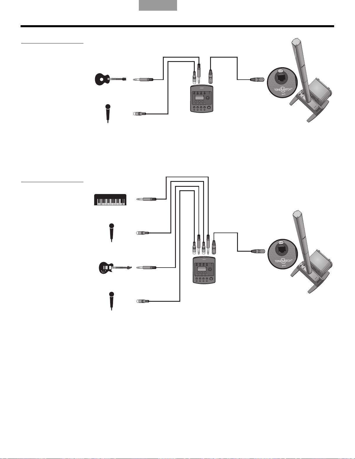
INFORMATIONS D’UTILISATION
Moteur audio
T1 ToneMatch
®
Moteur audio
T1 ToneMatch
Figure 2
Système unique avec
guitare et microphone
EnglishFrançaisFrançais DanskEspañolItalianoSvenska Nederlands
Plusieurs musiciens
Dans ce cas de figure, un duo piano-guitare chante et joue via un unique moteur audio
T1 ToneMatch et un système L1
®
.
Figure 3
Système unique avec
plusieurs instruments et
un moteur audio T1
Ton e
Ma tc h
16
Page 97

English Français FrançaisDansk Español Italiano SvenskaNederlands
Moteur audio
T1 ToneMatch
Moteur audio
T1 ToneMatch
Moteur audio
T1 ToneMatch
Moteur audio
T1 ToneMatch
INFORMATIONS D’UTILISATION
Orchestre
Dans le cas d’un orchestre, notre exemple sera basé sur plusieurs moteurs audio
T1 To ne Ma tc h
moteur audio T1 ToneMatch et un système L1.
Figure 4
Plusieurs systèmes, chacun
avec un moteur audio
T1 Ton eM at ch
®
et plusieurs systèmes L1®. Chaque musicien chante et joue via un unique
17
Page 98

INFORMATIONS D’UTILISATION
Figure 5
Deux systèmes, une table
de mixage et plusieurs
sources
EnglishFrançaisFrançais DanskEspañolItalianoSvenska Nederlands
Disc Jockey
Les DJ utilisent diverses sources (lecteur de CD, platine, lecteur MP3, etc.) connectées à une
table de mixage. Dans cet exemple, deux sorties d’une table de mixage peuvent être
connectées à deux systèmes L1
®
pour gérer le son en stéréo.
18
Page 99

English Français FrançaisDansk Español Italiano SvenskaNederlands
Entretien du produit
Nettoyage
• Pour nettoyer les boîtiers du système, utilisez uniquement un chiffon doux et sec.
• N’utilisez pas de solvants, de produits chimiques ni de liquides de nettoyage contenant de
ol, de l’ammoniaque ou des substances abrasives.
l’alco
• N’utilisez aucun aérosol à proximité du système et ne laissez aucun liquide pénétrer par
une des ouve
• Si nécessaire, vous pouvez utiliser avec précaution un aspirateur pour dépoussiérer la grille
de l’
enceinte L1
rtures.
®
.
Service après-vente
Pour toute aide en cas de problème, contactez le service clients de Bose® Live Music
Customer Service Product and Technical Support au numéro (877) 335 2673 (USA et Canada)
ou consultez le site Internet www.Bose.com/livesound.
Résolution des problèmes
ENTRETIEN
Si vous rencontrez des problèmes lors de l’utilisation de ce produit, essayez les solutions
suivantes. Si vous ne parvenez pas à résoudre le problème, contactez directement le service
clients de Bose
convenir d’un rendez-vous pour maintenance.
Outils de dépannage recommandés :
• Un voltmètre portable • Des câbles équipés de fiches XLR et Jack
• Un testeur de câbles • Câble à quatre broches pour module de
• Un testeur d’alimentation secteur • Un cordon d’alimentation secteur de
Pr
oblème Mesure corrective
Le système est branché au
r, l’interrupteur est
secteu
en position de marche,
mais la diode de mise sous
tension ne s’allume pas.
La diode de mise sous
tension es
(en ve
n’
est ém
t allumée
rt) mais aucun son
is.
• Vérifiez que la prise secteur f
autre appareil sur cette prise secteur, ou testez celle-ci à l’aide d’un voltmètre.
• Vérifiez que la fiche du cordon d’alimentation du socle amplificateur est bien insérée
da
• Vérifiez que le contrôle du volume n’est
• Assurez-vous que le niveau d’écrêtage (Trim) du
• Vérifiez que l’instrument est bien ra
• Connectez votre instrument au socle amplificateur à l’aide d’un autre câble.
• Branchez votre instrument à un autre amplificateur pour vous assurer qu’il fonctionne.
prise secteur.
ns la
®
Live Music Customer Service au (877) 335-2673 (USA et Canada) afin de
6,35 mm
graves
remplacement
onctionne. Essayez de faire fonctionner une lampe ou un
pas en position minimum sur votre instrument.
ccordé à la fiche Analog Input.
(¼")
B1
socle amplificateur est élevé.
La diode de mise sous
tension s’allum
lorsque le socle
amplificateur est sous
tension.
e en
rouge
• Contactez le support clientèle Bose Live Music Customer Support au numéro
(8
77) 335-2673 pour obtenir de l’aide.
19
Page 100

E
NTRETIEN
Problème Mesure corrective
EnglishFrançaisFrançais DanskEspañolItalianoSvenska Nederlands
Le disjoncteur du bâtiment
se déclenche
constamment.
Si aucune source n’est
br
an
chée dans le socle
amplificateur, un sifflement
ou un bourdonnement sont
émis
Le module de graves B1
ou
B2 est connecté, mais
aucun son grave n’est
émis.
Le volume du module de
grave
s B1 n’e
st pas
équilibré avec celui du
système.
Aucun son médium ou
aigu n’
est émis par
l’enceinte L1
®
.
• Si plusieurs socles amplificateurs sont branchés sur le même circuit d’alimentation,
v
eillez à échelonner leur mise sous tension. Chaque socle amplificateur a un courant de
démarrage en crête de 32 ampères lors de sa mise sous tension.
• Si plus de trois socles sont raccordés à un seul circuit de 15 ampères, branchez
ce
rt
ains systèmes sur un autre circuit électrique. Chaque socle amplificateur peut
nécessiter une intensité de 5 ampères ou plus lorsqu’il est utilisé à un fort volume
durant une longue période.
• À l’aide d’un testeur d’alimentation secteur, testez la prise secteur à laquelle est
br
anché le socle amplificateur pour vérifier l’absence de faux contacts ou de
branchements inversés (phase, neutre et/ou terre).
• Si vous utilisez une rallonge électrique, veillez
pr
écédemment.
• Utilisez le câble à quatre broches pour
module de graves B1/B2 fourni.
à la tester comme indiqué
• Vérifiez que le module de graves B1 ou B2 est correctement connecté à la prise
Bass Mo
dule Out du so
cle amplificateur.
• Essayez un autre câble à quatre broches.
• Si possible, essayez un autre module de graves B1/B2.
• Vérifiez que vous utilisez bien le câble à quatr
e broches pour module de graves B1/B2
fourni avec le module B1.
• Vérifiez que la grille du module de graves
B1 ou
B2 est orientée vers les musiciens et
le public.
• Vérifiez que les deux parties de l’enceinte L1 (array supérieure et extension inférieure)
so
nt correctement insérées dans leurs connecteurs.
• Vérifiez que les bornes de connexion ne sont pas pliées ou cassées.
• Essayez de nettoyer les bornes de connexion des deux parties de l’enceinte avec un
aé
r
osol adapté aux connexions électroniques.
Le son des instrument ou
de la
source audio est
distordu
Le microphone provoque
un pr
oblème de lar
sen
• Vérifiez que la diode rouge n’est pas constamment allumée. Si tel
est le cas, diminuez le
réglage d’écrêtage (Trim).
• Essayez avec une autre source.
• Essayez votre microphone sur un autre socle amplificateur.
• Orientez le microphone de façon à ce qu’il ne soit pas dirigé directement vers le
système L1 correspondant.
• Essayez un autre microphone.
• Modifiez la position de l’enceinte e
t/o
u du chanteur sur la scène.
• Augmentez la distance entre l’enceinte et le microphone.
• Si vous utilisez un processeur d’ef
fets pour voix, ass
urez-vous qu’il ne contribue pas au
problème de larsen.
20
 Loading...