

Bose L1 II Owner's Manual

L1® model II system
with ToneMatch® port
Owner’s Guide
Brugervejledning
Bedienungsanleitung
Guía de usuario
Notice d’utilisation
Manuale di istruzioni
Gebruiksaanwijzing
Bruksanvisningen
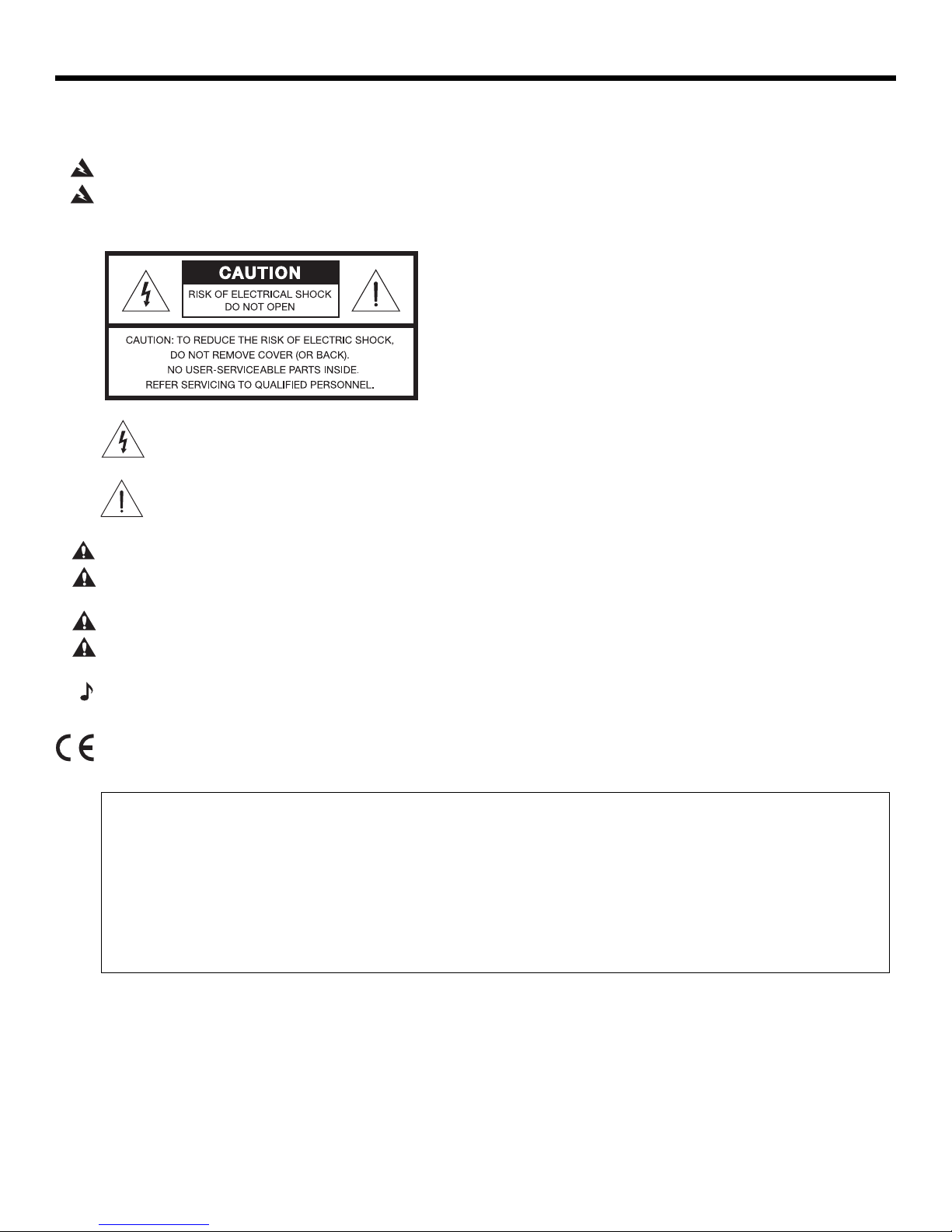
SAFETY INFORMATION
Please complete for your records
Now is a good time to record the serial numbers of your system here and on your product registration card.
You can register your product online at www.Bose.com/register or call (800) 905-1044. Failure to do so will
not affect your warranty rights.
L1
®
model II power stand _______________________________________________________________________
L1 model II loudspeaker ________________________________________________________________________
B2 bass module _______________________________________________________________________________
Please read this owner’s guide
Please take the time to follow the instructions in this owner’s guide carefully. It will help you set up and operate your
system properly and enjoy its advanced features. Please save this owner’s guide for future reference.
WARNING:
To reduce the risk of fire or electrical shock, do not expose the system to rain or moisture.
EnglishDeutschFrançais DanskEspañolItalianoSvenska Nederlands DanskItalianoSvenska DeutschNederlands EnglishFrançais Español
WARNING:
Refer servicing to qualified service personnel.
CAUTION:
CAUTION:
regulatory compliance, and system performance.
CAUTION:
CAUTION:
operable.
To reduce the risk of electric shock, do not disassemble this system unless you are qualified.
The lightning flash with arrowhead symbol within an equilateral triangle alerts the user to the presence
of uninsulated, dangerous voltage within the system enclosure that
constitute a risk of electrical shock.
The exclamation point within an equilateral triangle, as marked on the system, is intended to alert the user
to the pr
esence of important operating and maintenance instructions in this owner’s guide.
This product shall be connected to a mains socket outlet with a protective earthing connection.
Make no modifications to the system or accessories. Unauthorized alterations may compromise safety,
No naked flame sources, such as lighted candles, should be placed on the apparatus.
Where the mains plug is used as the disconnect device, such disconnect device shall remain readily
may be of sufficient magnitude to
Note: The product must be used indoors. It is neither designed nor tested for use outdoors, in recreation vehicles, or on
boats.
This product conforms to all applicable EU requireme
www.Bose.com/compliance.
©2012 Bose Corporation. No part of this work may be reproduced, modified, distributed, or otherwise used without prior written
permission.
nts.The complete Declaration of Conformity can be found at:

English Deutsch FrançaisDansk Español Italiano SvenskaNederlandsDansk Italiano SvenskaDeutsch NederlandsEnglish FrançaisEspañol
Information about products that
generate electrical noise
NOTE: This equipment has been tested and found to
comply with the limits for a Class A digital device,
pursuant to part 15 of the FCC Rules.These limits are
designed to provide reasonable protection against
harmful interference when the equipment is operated in
a commercial environment. This equipment generates,
uses, and can radiate radio frequency energy and, if
not installed and used in accordance with the
instruction manual, may cause harmful interference to
radio communications. Operation of this equipment in
a residential area is likely to cause harmful interference
in which case the user will be required to correct the
interference at their own expense.
Changes or modifications not expressly approved by
Bose Corporation could void the user's authority to
operate this equipment.
This Class A digital apparatus complies with Canadian
ICES-003.
Initial turn on inrush current: 32 Amps
Inrush current after AC mains interruption of 5 seconds:
32 Amps
This product meets all EN55103-2 immunity
requirements for E2 electromagnetic environment.
IMPORTANT SAFETY INSTRUCTIONS
1. Read these instructions.
2. Keep these instructions.
3. Heed all warnings.
4. Follow all instructions.
5. Do not use this apparatus near water.
6. Clean only with a dry cloth.
7. Do not block any ventilation openings. Install in
ac
cordance w
tions.
8. Do not install near any heat sources, such as
radiators, hea
ratus (including amplifiers) that produce heat.
9. Do not defeat the safety purpose of the polarized or grounding-type plug. A polarized plug
has two blades with one wider than the other
grounding-type plug has two blades and a third
grounding prong. The wider blade or third prong
is provided for your safety. If the provided plug
does not fit into your outlet, consult an electrician for replacement of the obsolete outlet.
10. Protect the power cord from being walked on or
pinche
receptacles, and the point where they exit from
the apparatus.
11. Only use attachments/accessories specified by
the manufacturer.
Use only with the cart, stand, tripod,
12.
bracket, or table specified by the manufacturer or sold with the apparatus.
When a cart is used, use caution
moving the cart/apparatus combination to avoid
injury from tip-over.
13. Unplug this apparatus during lightning storms
or when unused for long
d, particularly at plugs, convenience
ith the manufacturer’s instruc-
t registers, stoves, or other appa-
when
periods of time.
14.
Refer all servicing to qualified service personnel.
Servicing is required when the apparatus has
been damaged in any way, such as power-supply
cord or plug is damaged, liquid has been spilled
or objects have fallen into the apparatus, the
apparatus has been exposed to rain or moisture,
does not operate normally, or has been dropped.
15. To prevent risk of fire or electric shock, avoid
overloading wall
integral convenience receptacles.
16. Do not let objects or liquids enter the product –
as they ma
circuit parts that could result in a fire or electric shock.
17. See product enclosure bottom for safety-related
markings.
. A
18. Use proper power sources – Plug the produ
a proper power source, as described in the operating
instructions or as marked on the product.
19. Apparatus shall not be exposed to dripping or
splashing, and no objects filled
such as vases, shall be placed on the apparatus.
y touch dangerous voltage points or short-
outlets, extens
ion cords, or
ct into
with liquids,
Venice_SafetyInstructions.fm 8/12

EnglishDeutschFrançais DanskEspañolItalianoSvenska Nederlands DanskItalianoSvenska DeutschNederlands EnglishFrançais Español
INTRODUCTION 5
Welcome . . . . . . . . . . . . . . . . . . . . . . . . . . . . . . . . . . . . . . . . . . . . . . . . . . . . . . . . . . . . . . . . . . . . . . . . . . . . . . . . . . . 5
Features and benefits . . . . . . . . . . . . . . . . . . . . . . . . . . . . . . . . . . . . . . . . . . . . . . . . . . . . . . . . . . . . . . . . . . . . . . . . . 5
Product overview . . . . . . . . . . . . . . . . . . . . . . . . . . . . . . . . . . . . . . . . . . . . . . . . . . . . . . . . . . . . .
Connections and controls . . . . . . . . . . . . . . . . . . . . . . . . . . . . . . . . . . . . . . . . . . . . . . . . . . . . . . . . .
. . . . . . . . . . . . . . . . 6
. . . . . . . . . . . . . 7
SYSTEM SETUP 8
Parts list . . . . . . . . . . . . . . . . . . . . . . . . . . . . . . . . . . . . . . . . . . . . . . . . . . . . . . . . . . . . . . . . . . . . . . . . . . . . . . . . . . . . 8
Positioning your system . . . . . . . . . . . . . . . . . . . . . . . . . . . . . . . . . . . . . . . . . . . . . . . . . . . . . . . . . . . . . . . . . . . . . . . . 9
Setting up the L1
Assembling the L1 model II top and bottom array loudspeakers . . . . . . . . . . . . . . . . . . . . . . . . . . . . . . . . . . . . . . .
®
model II power stand . . . . . . . . . . . . . . . . . . . . . . . . . . . . . . . . . . . . . . . . . . . . . . . . . . . . . . . . . . . 10
. 10
Connecting to AC power . . . . . . . . . . . . . . . . . . . . . . . . . . . . . . . . . . . . . . . . . . . . . . . . . . . . . . . . . . . . . . . . . . . . . . . 11
Connecting the B1 bass module . . . . . . . . . . . . . . . . . . . . . . . . . . . . . . . . . . . . . . . . . . . . . . . . . . . . . .
Adding a T1 ToneMatch
Adding a second B1 bass module (optional) . . . . . . . . . . . . . . . . . . . . . . . . . . . . . . . . . . . . . . . . . . . . . . . . . . . . . . . . 14
Adding a PackLite
®
audio engine (optional) . . . . . . . . . . . . . . . . . . . . . . . . . . . . . . . . . . . . . . . . . . . . . . . . . . . . 13
®
power amplifier model A1 (optional) . . . . . . . . . . . . . . . . . . . . . . . . . . . . . . . . . . . . . . . . . . . . . . . 15
Connecting multiple B1 bass modules . . . . . . . . . . . . . . . . . . . . . . . . . . . . . . . . . . . . . . . . . . . . . . . . . . . .
Connecting a second B2 module . . . . . . . . . . . . . . . . . . . . . . . . . . . . . . . . . . . . . . . . . . . . . . . . . . . . . . .
. . . . . . . . . . . 12
. . . 15
. . . . . 16
OPERATING INFORMATION 17
Setting the analog input level . . . . . . . . . . . . . . . . . . . . . . . . . . . . . . . . . . . . . . . . . . . . . . . . . . . . . . . . . . . . . . . . . . . . 17
Using a T1 ToneMatch® audio engine and an analog input source . . . . . . . . . . . . . . . . . . . . . . . . . . . . . . . . . . . . . . . 17
User scenarios . . . . . . . . . . . . . . . . . . . . . . . . . . . . . . . . . . . . . . . . . . . . . . . . . . . . . . . . . . . . .
Single musician . . . . . . . . . . . . . . . . . . . . . . . . . . . . . . . . . . . . . . . . . . . . . . . . . . . . . . . . . . . . . .
Multiple musicians . . . . . . . . . . . . . . . . . . . . . . . . . . . . . . . . . . . . . . . . . . . . . . . . . . . . . . . . . . . .
Full band . . . . . . . . . . . . . . . . . . . . . . . . . . . . . . . . . . . . . . . . . . . . . . . . . . . . . . . . . . . . . . . . .
DJ events . . . . . . . . . . . . . . . . . . . . . . . . . . . . . . . . . . . . . . . . . . . . . . . . . . . . . . . . . . . . . . . .
. . . . . . . . . . . . . . . . . . 17
. . . . . . . . . . . 17
. . . . . . . . . . . 18
. . . . . . . . . . . . . . 19
. . . . . . . . . . . . . . 20
CARE AND MAINTENANCE 21
Caring for your product . . . . . . . . . . . . . . . . . . . . . . . . . . . . . . . . . . . . . . . . . . . . . . . . . . . . . . . . . . . . . . . . . . . . . . . . 21
Cleaning . . . . . . . . . . . . . . . . . . . . . . . . . . . . . . . . . . . . . . . . . . . . . . . . . . . . . . . . . . . . . . . . .
Getting service . . . . . . . . . . . . . . . . . . . . . . . . . . . . . . . . . . . . . . . . . . . . . . . . . . . . . . . . . . . . .
Troubleshooting . . . . . . . . . . . . . . . . . . . . . . . . . . . . . . . . . . . . . . . . . . . . . . . . . . . . . . . . . . . . . .
Limited Warranty and Registration . . . . . . . . . . . . . . . . . . . . . . . . . . . . . . . . . . . . . . . . . . . . . . . . . . . . .
Accessories . . . . . . . . . . . . . . . . . . . . . . . . . . . . . . . . . . . . . . . . . . . . . . . . . . . . . . . . . . . . . . .
Technical Information . . . . . . . . . . . . . . . . . . . . . . . . . . . . . . . . . . . . . . . . . . . . . . . . . . . . . . . . . .
Mechanical . . . . . . . . . . . . . . . . . . . . . . . . . . . . . . . . . . . . . . . . . . . . . . . . . . . . . . . . . . . . . . . .
Electrical . . . . . . . . . . . . . . . . . . . . . . . . . . . . . . . . . . . . . . . . . . . . . . . . . . . . . . . . . . . . . . . . .
Audio Input/Output . . . . . . . . . . . . . . . . . . . . . . . . . . . . . . . . . . . . . . . . . . . . . . . . . . . . . . . . . . . .
. . . . . . . . . . . . . . 21
. . . . . . . . . . . . . 21
. . . . . . . . . . . . . . . . 21
. . . . . . . . . . . 23
. . . . . . . . . . . . . . . . . . 23
. . . . . . . . . . . . . . . . 23
. . . . . . . . . . . . . 23
. . . . . . . . . . . . . . 23
. . . . . . . . . . . 23
4

English Deutsch FrançaisDansk Español Italiano SvenskaNederlandsDansk Italiano SvenskaDeutsch NederlandsEnglish FrançaisEspañol
INTRODUCTION
Welcome
Thank you for purchasing the Bose® L1® model II system with ToneMatch® port. Based on a
revolutionary new technology, this system brings the benefits of an intimate acoustic concert
to amplified performance.
This owner’s guide provides detailed setup an
system and explains how to connect equipment to it.
For additional information on using this system, including tips, tec
asked questions, please visit www.Bose.com/livesound on the Internet.
Features and benefits
• You control the sound – Just as in an unamplified performance, you control the sound.
You will no longer wonder how you sound to your fellow musicians or to your audience
because you will hear what they hear.
• Q
uick and easy setup – The L1 model II
utes, not hours. This frees you from the time-consuming and often frustrating effort
required
• Dramatically improved performa
performance and enjoyment dramatically improve because the struggle to hear yourself
and the other musicians is diminished.
• Cr
kind o
• You hear what the audience hears – For the fi
audiences hear and thus, are less likely to play at uncomfortable sound levels.
• The music is naturally dynamic
heard and enjoyed.
• Improves your appearance – There
• Sound reproduction unlike before – Audien
excitement that come from hearing the accurate reproduction of sound from each
instrument, and from hearing the sound of each instrument in its position on stage
(as opposed to mono or even stereo mix of all instruments), is unlike anything they have
he
d opera
system is easy to carry and can be set up in min-
to properly set up conventional sound equipment.
nce – Compared to using conventional equipment,
eates excitement and emotion – Enhanced performance of the musicians creates the
f excitement and emotion that is valued by music lovers.
– The softest to the most intense passages can be
is less equipment on the stage and more room.
ard befo
re in an amplified performance.
ting instructions for your L1 model II
hniques, and frequently
rst time, musicians hear what their
ce members report that the clarity and
5
Venice_Intro.fm 8/12
I
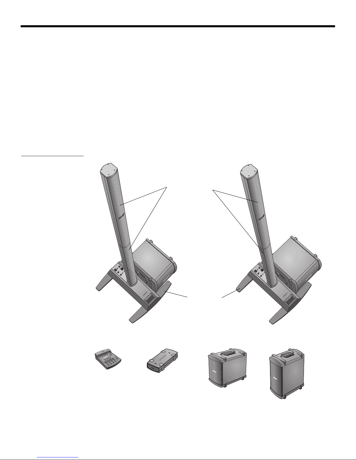
L1 model II top and
bottom arrays
L1 model II
power stand
L1 model II system with ToneMatch port
Optional equipment
B1 bass
module
PackLite power
amplifier model A1
T1 ToneMatch
audio engine
Additional B1
bass module
B2 bass module
B2 bass
module
NTRODUCTION
Product overview
Figure 1
L1 model II system and
optional equipment
EnglishDeutschFrançais DanskEspañolItalianoSvenska Nederlands DanskItalianoSvenska DeutschNederlands EnglishFrançais Español
The L1® model II system – with ToneMatch® port consists of the power stand, top and bottom
loudspeaker arrays, and a B1 or B2 bass module. The system also comes with a
padded carrying bag for each of its parts.
To expand your system and enhance performance, you can add:
• A second B1 bass module for bass guitar, kick drum, or organ. Each power stand can
power up to two
B1 bass modules or a single B2 bass module.
• A T1 ToneMatch audio engine for digital signal processing, additional inputs and user-interface control.
• A PackLite
®
power amplifier model A1 for adding up to two more B1 bass modules or one
more B2 bass module to your system.
For a complete list of optional equipment and accessories, please visit:
www.Bose.com/livesound.
6
Venice_Intro.fm 8/12
English Deutsch FrançaisDansk Español Italiano SvenskaNederlandsDansk Italiano SvenskaDeutsch NederlandsEnglish FrançaisEspañol
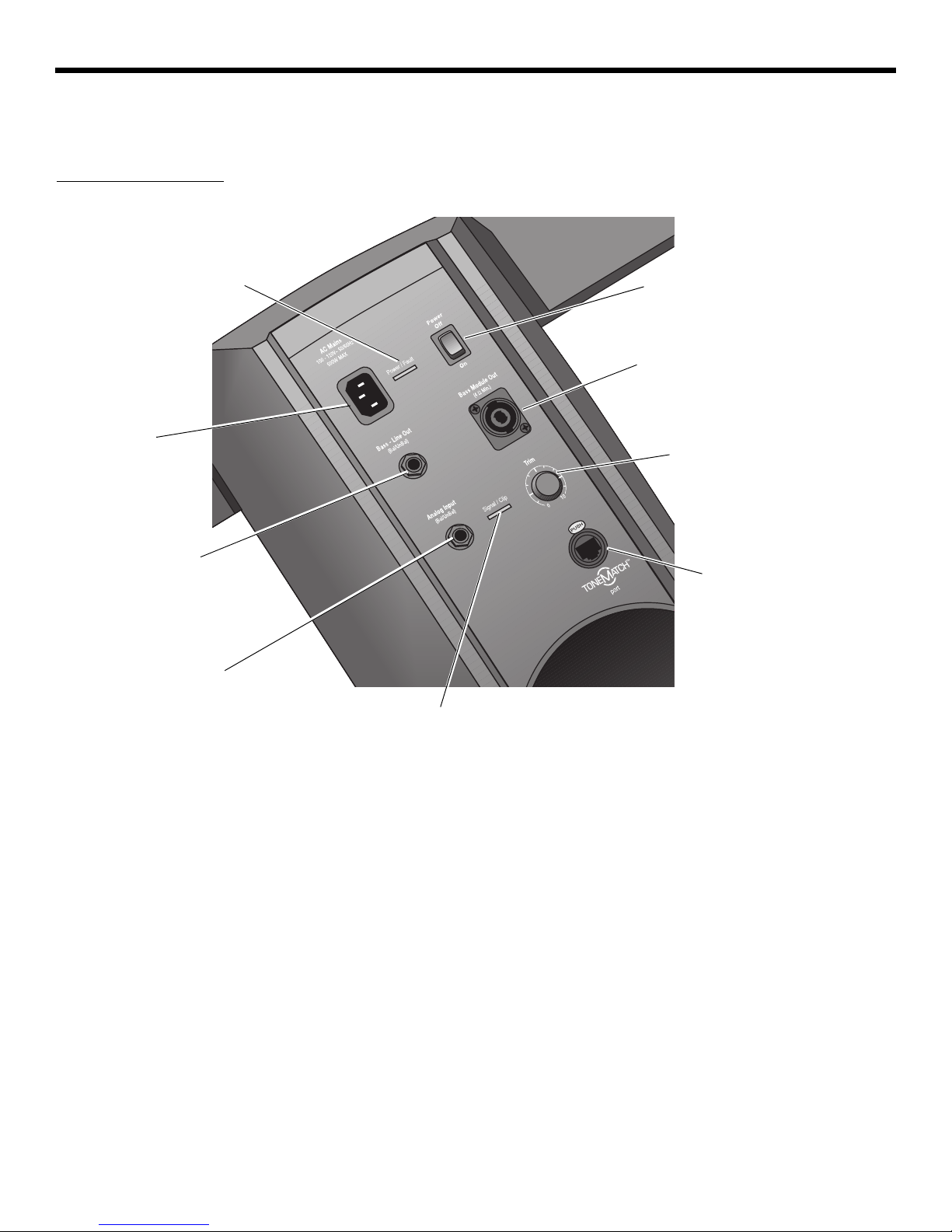
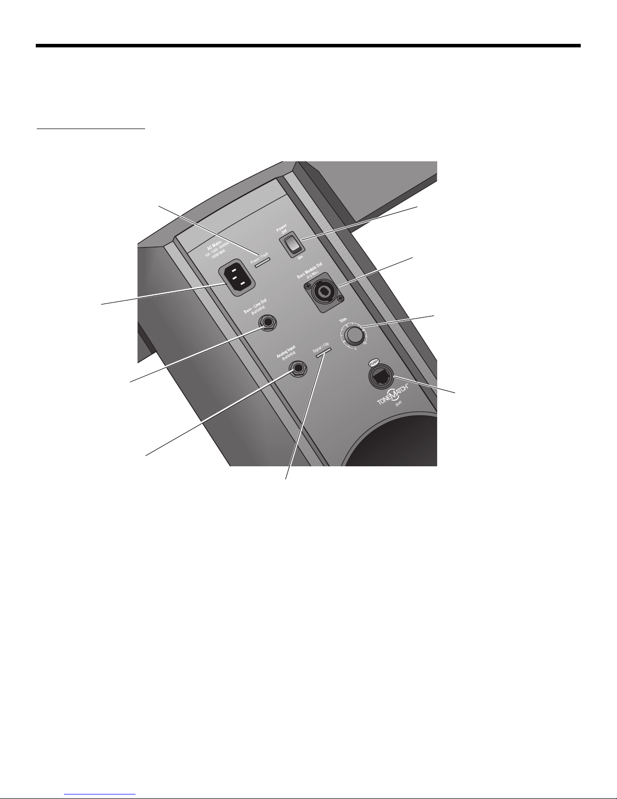
Power switch
Switches the system
on and off.
AC Mains
AC power input
connector.
Bass - Line Out
Post-DSP bass signal output.
Accepts a ¼" TRS phone cable.
Used to drive a PackLite
®
power
amplifier.
Bass Module Out
Bass output signal for driving one B2
or two B1 bass modules. Accepts a
4-wire bass module cable.
Trim
Adjusts the level of the
analog input signal.
Ton eM atc h
®
port
Digital audio and power connection for the optional T1
ToneMatch audio engine.
Accepts the included
ToneMatch cable.
Analog Input
A line-level analog input. Accepts
a ¼" TRS phone cable. Used for
an instrument or other audio
source.
Signal/Clip LED
Indicates status of the analog input signal.
Green = normal input
Yellow = input approaching clipping
Red = input clipping
Power/Fault LED
Indicates power status.
Blue = system on
Red = system fault
Connections and controls
The top panel of the power stand provides system connectors and controls (Figure 2).
Figure 2
Power stand top panel
I
NTRODUCTION
7
Venice_Intro.fm 8/12
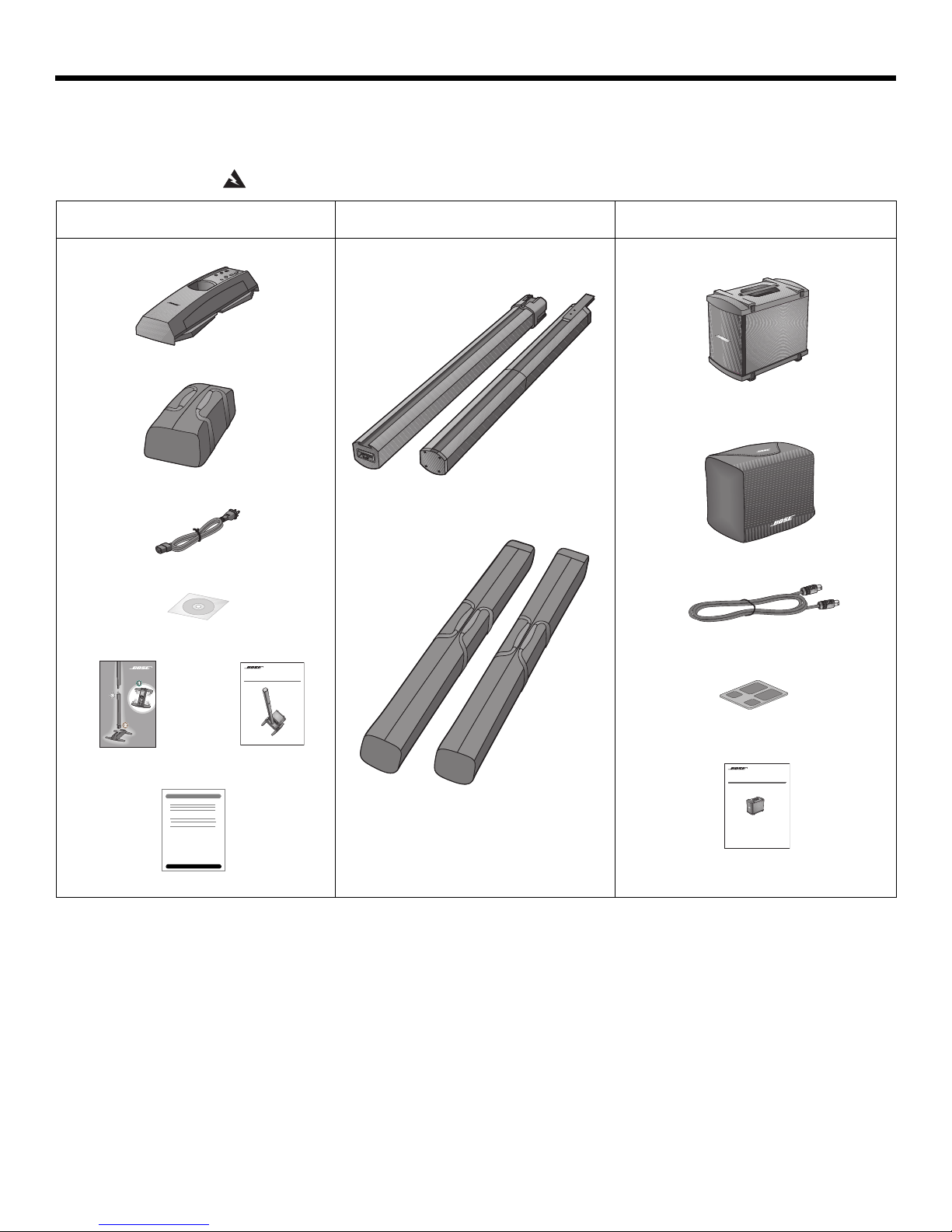
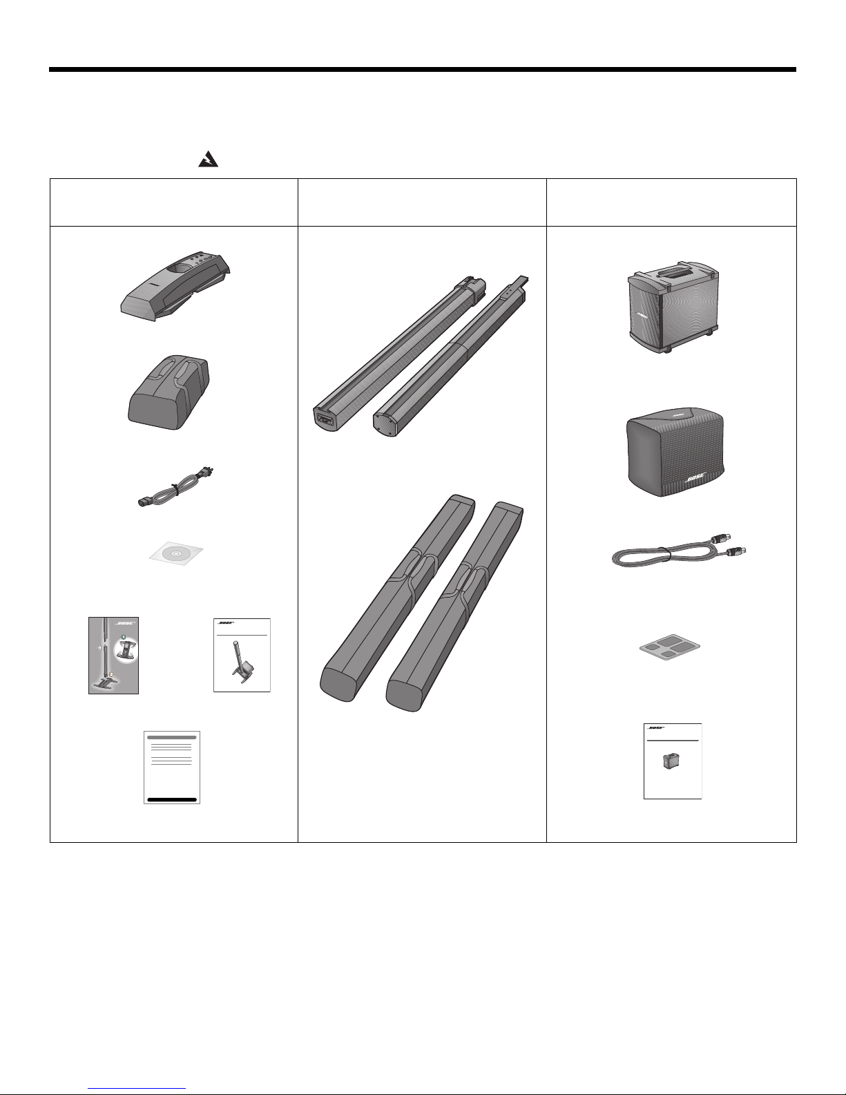
Parts list
L1TM Model II System
with ToneMatchTM port
Owner’s Guide
www.Bose.com/musicians
Top
Bottom
B1
Bass Module
Installation Guide
Power stand carton Top and bottom array carton B1 or B2 bass module carton
EnglishDeutschFrançais DanskEspañolItalianoSvenska Nederlands DanskItalianoSvenska DeutschNederlands EnglishFrançais Español
SYSTEM SETUP
The L1® model II system is shipped in three cartons. Carefully unpack the cartons and check
that you have all the items listed on this page.
WARNING:
To avoid danger of suffocation, keep the plastic bags out of the reach of children.
L1 model II power stand
Carrying bag
AC power cord
Demonstration CD
Quick setup guide Owner’s guide
L1 model II
Top and bottom loudspeaker arrays
Carrying bags
B1 or B2 bass module
Cover
Bass module cable (4-wire)
Adhesive rubber feet (for B2 only)
B1 or B2 bass module owner’s guide
Product registration card
8
English Deutsch FrançaisDansk Español Italiano SvenskaNederlandsDansk Italiano SvenskaDeutsch NederlandsEnglish FrançaisEspañol
Good
Better
Best
3 ft
(0.9 m)
5 ft
(1.5 m)
7-8 ft
(2.1-2.4 m)
3 ft
(0.9 m)
3 ft
(0.9 m)
3 ft
(0.9 m)
3 ft
(0.9 m)
5 ft
(1.5 m)
5 ft
(1.5 m)
5 ft
(1.5 m)
5 ft
(1.5 m)
7-8 ft
(2.1-2.4 m)
7-8 ft
(2.1-2.4 m)
7-8 ft
(2.1-2.4 m)
7-8 ft
(2.1-2.4 m)
Positioning your system
Placing the power stand in the right location is an important part of setting up this product.
Determining the best location for your performance depends on several things.
• Size of staging area
• Number of performers
• Shared system (adding a T1 ToneMatch
The following guidelines should get yo
• Set up your system in the rear area of the performance stage.
• If possible, position your system be
• If you are part of a group, avoid crowding together on stage. Allow some distance,
ideally 7-8 feet (2.1-2.4 m), between you and the L1
performer. This allows the sound to wrap around performers and reflect off adjacent
surfaces of the room, creating a mor
Figure 1
Placement
recommendations
SYSTEM SETUP
®
audio engine and multiple instruments)
u started in setting up for a concert or show.
hind the performer(s).
®
model II system and another
e pleasing room-filling sound.
9
SYSTEM SETUP
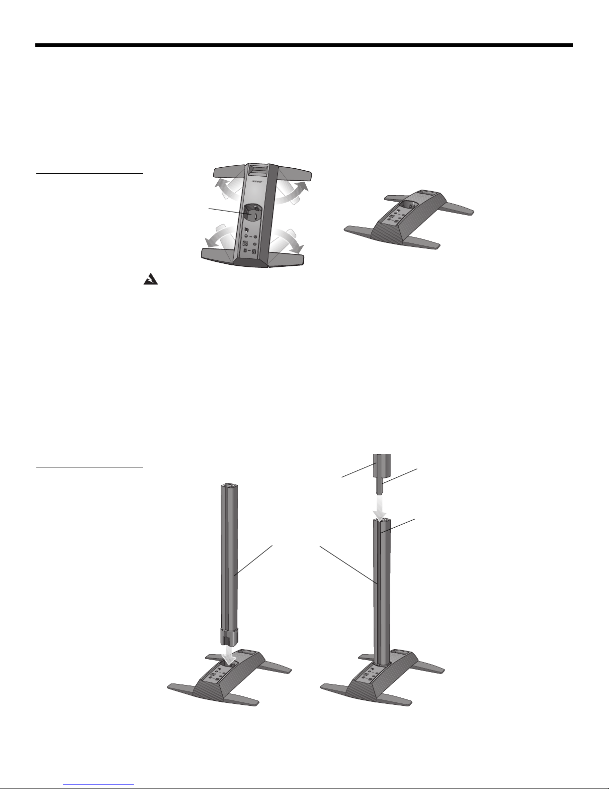
A
B
Socket for
L1 bottom
L1 top
L1 bottom
Bayonet
Channel
A
B
Front of
system
Setting up the L1® model II power stand
1. Holding the power stand vertically on the floor (Figure 2A), grasp one leg and swing it out
as far as it will go. Notice that the other legs swing out automatically.
The legs must be fully open befor
the power stand.
2. Lay the power stand flat on the floor in the desired position (Figure 2B).
Figure 2
Putting the power stand on
the floor
e you can plug the L1
EnglishDeutschFrançais DanskEspañolItalianoSvenska Nederlands DanskItalianoSvenska DeutschNederlands EnglishFrançais Español
®
bottom section into
WARNING: DO NOT move the completely assembled system as a unit. This could result in
personal injury and/or damage to the product. Position the power stand on the floor in the
chosen location before assembling the system.
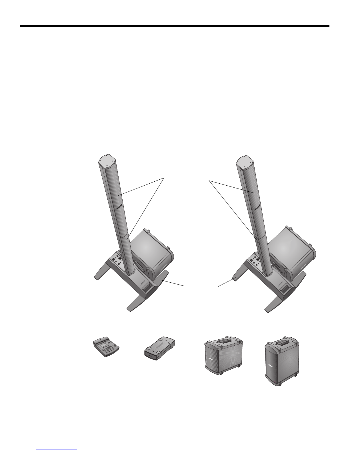
Assembling the L1 model II top and bottom array loudspeakers
Figure 3
Setting up the L1 model II
top and bottom arrays
This procedure tells you how to set up the loudspeaker sections in the power stand. If you
plan to mount the T1 ToneMatch
To ne M at c h
®
audio engine (optional)” on page 12 before installing the top section of the loud-
speaker.
1. Hold the L1 bottom so that the grille faces front and plug it into the power stand (Figu
3A). Be sure to fully insert it into the socket to assure stability and
2. Align the bayonet on the L1 top with the channel on the back of the L1 bottom, and lower
the L1 to
p onto the L1 bottom until it is flush (Figure 3B).
®
audio engine on the L1 model II system, see “Adding a T1
re
a good connection.
10
English Deutsch FrançaisDansk Español Italiano SvenskaNederlandsDansk Italiano SvenskaDeutsch NederlandsEnglish FrançaisEspañol
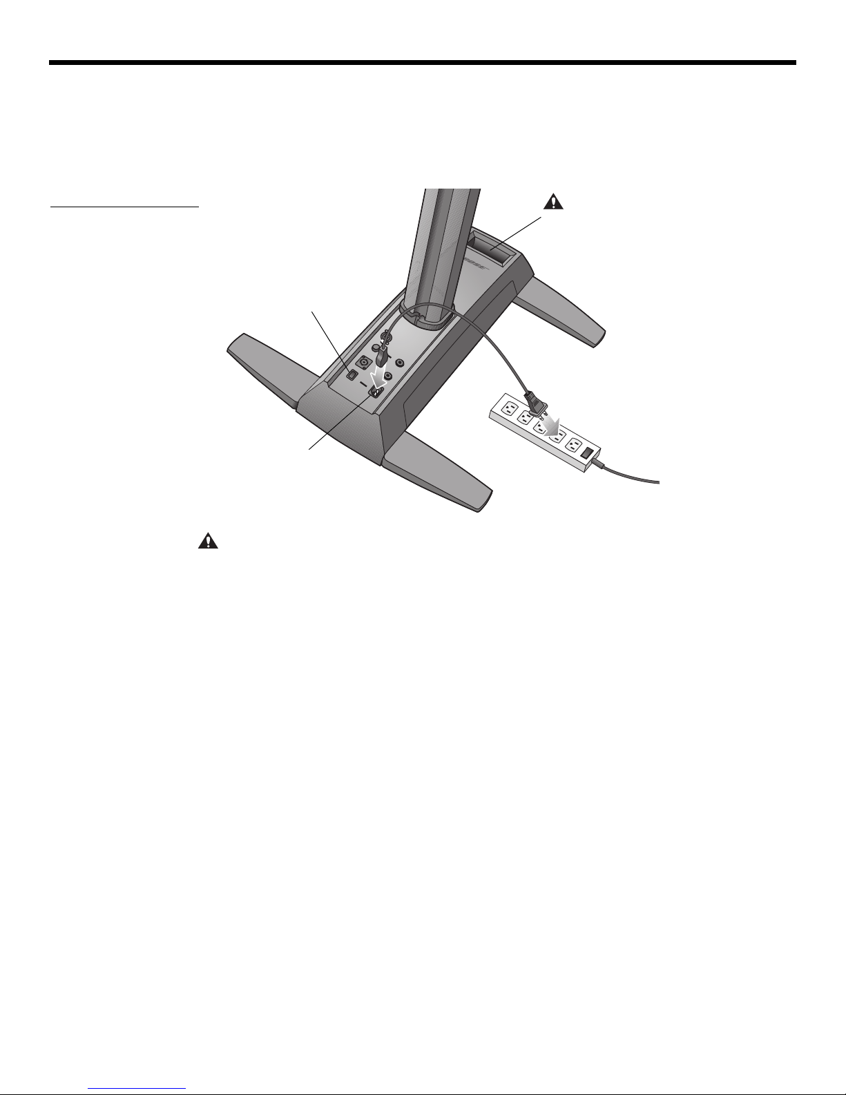
AC Mains
CAUTION: DO NOT block or cover
the handle opening, which is part of
the ventilation system. Doing so can
cause the L1
®
model II system to
overheat, switch to a thermal protection mode, and temporarily turn off.
Power switch
Connecting to AC power
1. Make sure the power switch is off.
2. Plug one end of the AC power cord into the AC Mains connector on
3. Plug the other end into a live AC (mains) receptacle (Figure 4).
Figure 4
Power connections
SYSTEM SETUP
the power stand.
CAUTION: Bose recommends using a quality surge suppressor on all electronic equipment.
Voltage variations and spikes can damage electronic components in any
system. A quality
suppressor, which can eliminate the vast majority of failures attributed to surges, may be purchased at electronics stores.
11
SYSTEM SETUP
B1
Bass Module
Out
Bass Module
Out
B2
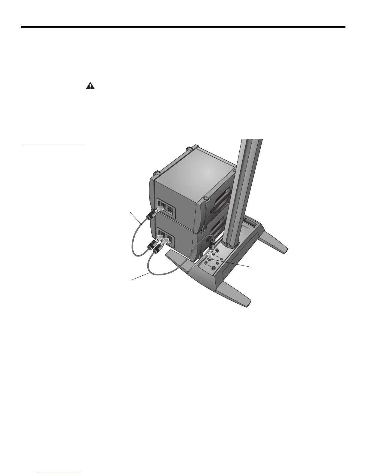
Connecting the B1 bass module
You can place the B1 or B2 bass module either vertically or horizontally on the floor. It fits
neatly between the legs of the power stand.
1. Plug one end of the B1 or B2 bass module cable into one of the bass connectors. Rotate
Figure 5
B1 bass module
the plug clo
2. Plug the other end of the cable into the Bass Module Out connec
stand. Rotate the plug clockwise to lock it.
Note:
To disconnect a B1 or B2 cable, slide back the metal tab on the body of the plug, rotate
the plug counterclockwise, and pull it out of the connector.
ckwise to lock it in place. You should hear a soft click as it locks.
EnglishDeutschFrançais DanskEspañolItalianoSvenska Nederlands DanskItalianoSvenska DeutschNederlands EnglishFrançais Español
tor on the power
CAUTIONS:
• DO NOT connect a B1 bass module to two power stands at the same time.
• DO NOT connect any bass module other than the B1 or B2 to the power stand.
• DO NOT substitute the supplied cable with a 2-wire speaker cable. Use only the supplied
4-wire ca
signals on two of the wires (or the position of the B2 rear panel switch) to automatically
sense how many bass modules are connected.
ble to connect the bass module to the power stand. The power stand uses the
12

English Deutsch FrançaisDansk Español Italiano SvenskaNederlandsDansk Italiano SvenskaDeutsch NederlandsEnglish FrançaisEspañol
4
5
6
Carriage
Mounting bar
L1 model II
bottom array
T1 ToneMatch
audio engine
1
2
3
Locking knob
Power stand
Hook and loop strap
T1 ToneMatch
audio engine
L1 model II
bottom array
ToneMatch cable
(supplied with T1)
Adding a T1 ToneMatch® audio engine (optional)
The T1 ToneMatch® audio engine provides additional input/output capabilities to your
system, plus digital signal processing to customize th
comes with hardware for mounting it on the left or right side of the L1
bottom arrays.
Note:
The audio engine mounts on the bottom section of the loudspeaker and requires removal
of the top section before starting this procedure.
1. Slide the carriage into the channel on the rear of the L1 bottom and turn the knob
clockwise to lock it in place (Figure 6).
2. Insert the mounting bar into the slot in the carriage and push it downward.
3. Place the T1 on the mounting bar as shown.
4. Plug one end of the ToneMatch cable (supplied with the audio engine) into the
ToneMatch output port (
5. Using the hook and loop strap, secure the cable to the carriage.
6. Plug the other end of the cable into the ToneMatch port on the power stand.
Figure 6
Mounting the T1
) on the T1.
SYSTEM SETUP
e way you sound. The audio engine
®
model II top and
13
SYSTEM SETUP
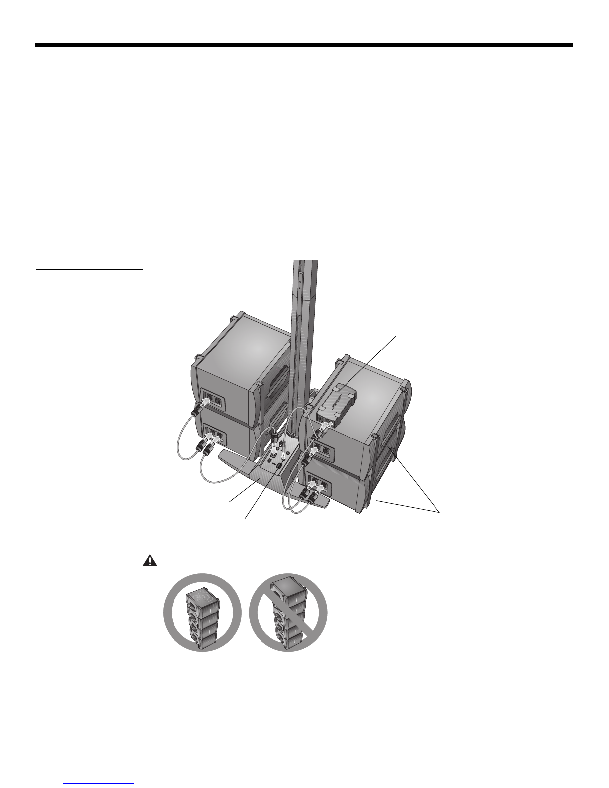
Second B1
bass module
cable
First B1 bass
module cable
Bass Module Out
Adding a second B1 bass module (optional)
The bass module output of the power stand can adequately drive one or two B1 bass
modules. When placed horizontally, the modules are stackable (Figure 7).
One or two additional B1 modules can be added with the use of a PackLite
Refer to “Adding a PackLite
®
power amplifier model A1 (optional)” on page 15.
EnglishDeutschFrançais DanskEspañolItalianoSvenska Nederlands DanskItalianoSvenska DeutschNederlands EnglishFrançais Español
®
power amplifier.
Figure 7
Installation of two B1 bass
modules
CAUTION:
Do not connect more than two B1 bass modules to the Bass Module Out
connector on the power stand. Driving more than two B1 bass modules from this output
improperly loads the amplifier in the power stand, resulting in less than full system performance.
1. Connect the first B1 to the Bass Module Ou
t connector on the power stand.
2. Plug one end of the second B1 cable into the unused connector of the first B1. Plug the
other end o
f the cable into one of the connectors of the second B1.
14
English Deutsch FrançaisDansk Español Italiano SvenskaNederlandsDansk Italiano SvenskaDeutsch NederlandsEnglish FrançaisEspañol
Additional B1
bass modules
Power stand
PackLite
®
power
amplifier
Bass - Line Out
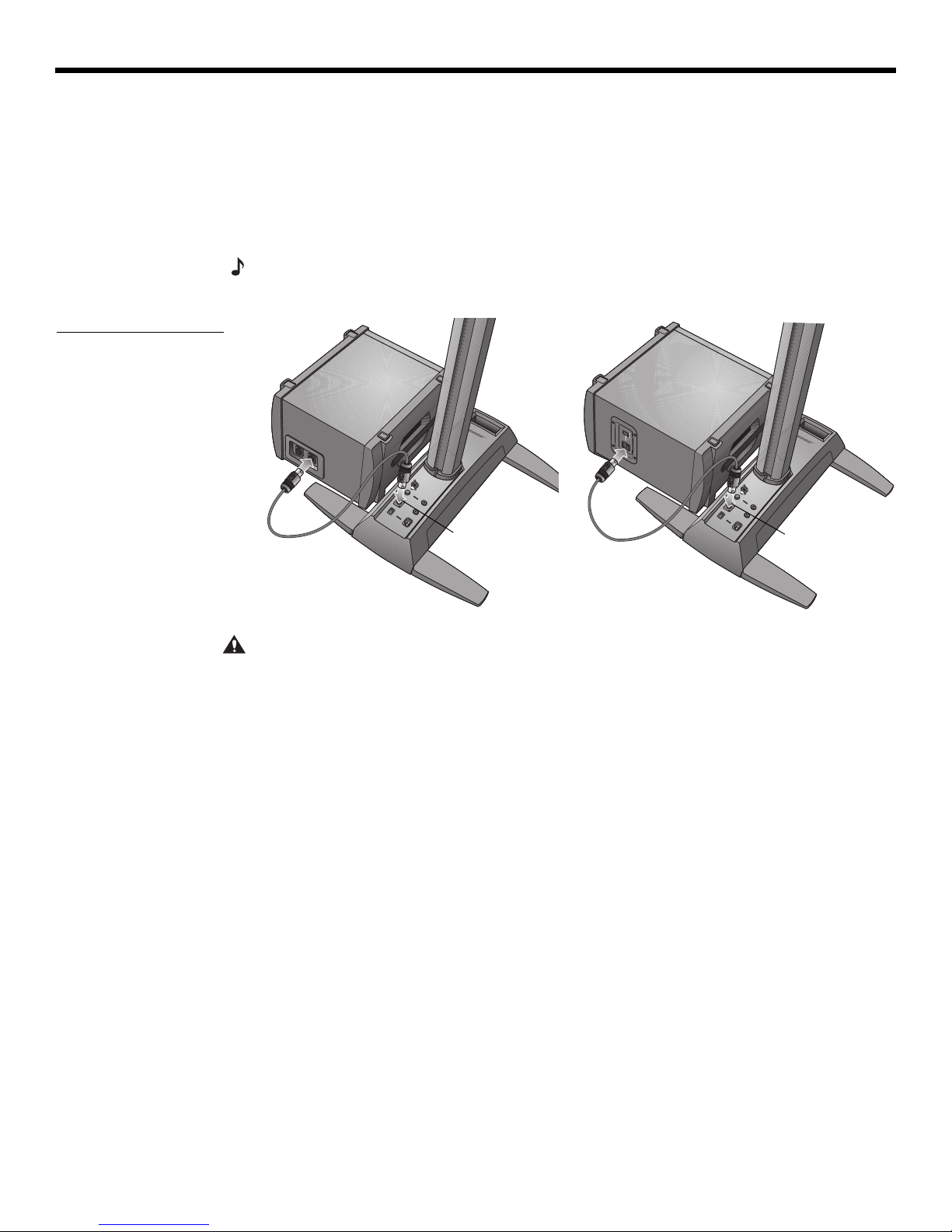
Adding a PackLite® power amplifier model A1 (optional)
Connecting multiple B1 bass modules
Using a PackLite® power amplifier model A1 allows you to add one or two additional B1
modules to your system. Refer to the A1 owner’s guide for detailed operating instructions.
Figure 8
Connecting the A1
amplifier to the power
stand
1. Make sure the A1 amplifier power switch is OFF.
2. Plug one end of the supplied ¼" TRS cable into the Bass - Line Out connecto
power stand. Plug the other end into the INPUT connector on the A1 amplifier.
3. Connect a B1 bass module cable from the OUTPUT connector
module. If desired, connect a second B1 to the first B1.
4. Plug one end of the AC power cord into the A1 amplifier and plug the other end into an
AC (mains) outlet.
5.
Switch the A1 power switch to ON (I).
SYSTEM SETUP
r on the
on the A1 to a B1 bass
CAUTION: DO NOT stack more than four B1 modules in a column.
15
SYSTEM SETUP
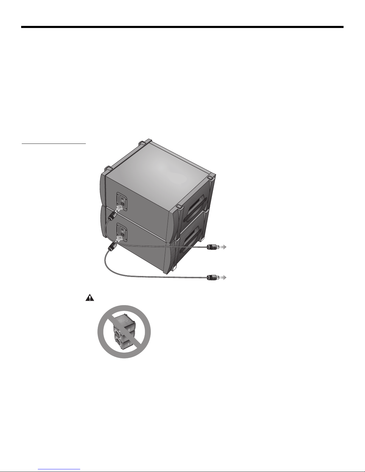
To power stand Bass Module Out
To PackLite amplifier OUTPUT
Figure 9
Connecting two
B2 bass modules
EnglishDeutschFrançais DanskEspañolItalianoSvenska Nederlands DanskItalianoSvenska DeutschNederlands EnglishFrançais Español
Connecting a second B2 module
Using a PackLite® power amplifier model A1 allows you to add one additional B2 module to
your L1 model II system.
1. Make sure the A1 amplifier power switch is OFF.
2.
Plug one end of the supplied ¼" TRS cable into the Bass - Line Out connecto
power stand. Plug the other end into the INPUT connector on the A1 amplifier.
3. Connect a B2 bass module cable from the OUTPUT connecto
r on the A1 to the B2 bass
module.
4. Plug one end of the AC power cord into the A1 amplifier and plug the other end into an
AC (mains) outlet.
5.
Switch the A1 power switch to ON (I).
r on the
CAUTION: DO NOT stack more than two B2 modules.
16

English Deutsch FrançaisDansk Español Italiano SvenskaNederlandsDansk Italiano SvenskaDeutsch NederlandsEnglish FrançaisEspañol
OPERATING INFORMATION
Setting the analog input level
When connecting an audio source to the Analog Input, follow these steps to adjust the input
Trim control.
1.
Set the Trim control on the power stand to the 0 (zero) position.
2. Connect the audio source to the Analog Input.
3. Adjust
4. While playing the source, increase the Tr
5. If the Signal/Clip indica
Using a T1 ToneMatch® audio engine and an analog input source
The L1® model II system can operate with both a T1 ToneMatch® audio engine and an analog
audio source connected to the power stand. However, keep in mind that the volume level of
the audio engine and the analog audio source is adjusted independently.
• The power stand Tr
nected to the Analog Input. Ther
of the analog input signal.
• The T1 ToneMatch audio engine has a Trim cont
a Volume control for each output channel, and a Master volume control that adjusts the
level of the ToneMatch output sent to the power stand. These controls have no effect on
the signal fed to the Analog Input.
the volume of the audio source to the desired level.
im level until the Signal/Clip in
green or yellow.
tor glows red, decrease the Trim level so that it glows only green
or yellow.
im control on
ly affects the volume level of the analog audio source con-
efore, the Signal/Clip indicator indicates the status only
rol and signal/clip indicator for each input,
dicator glows
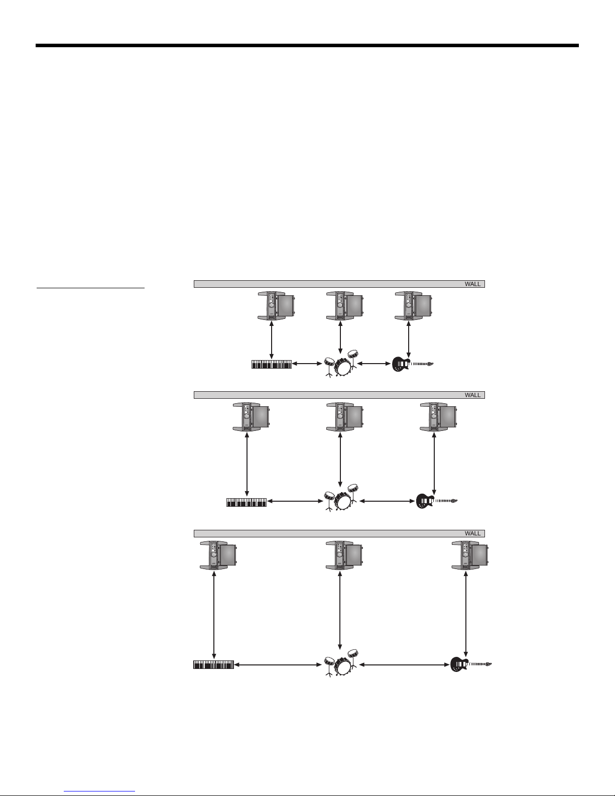
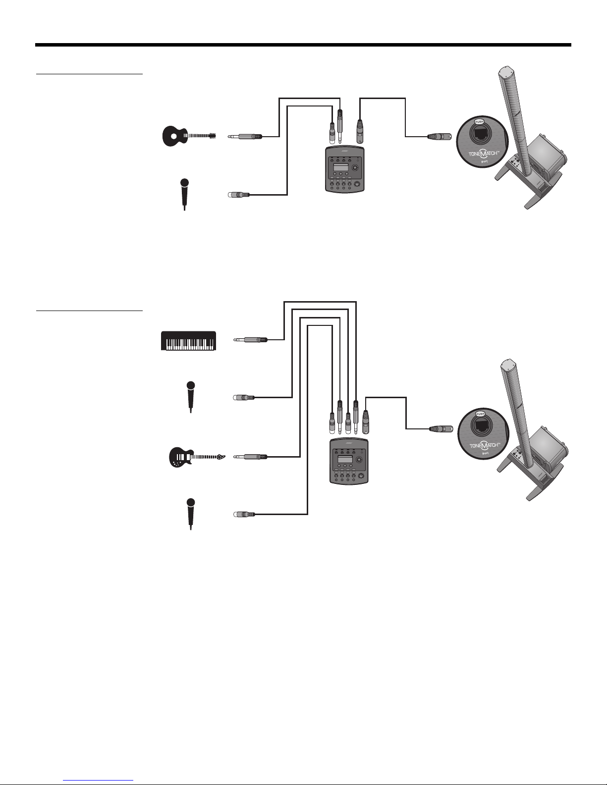
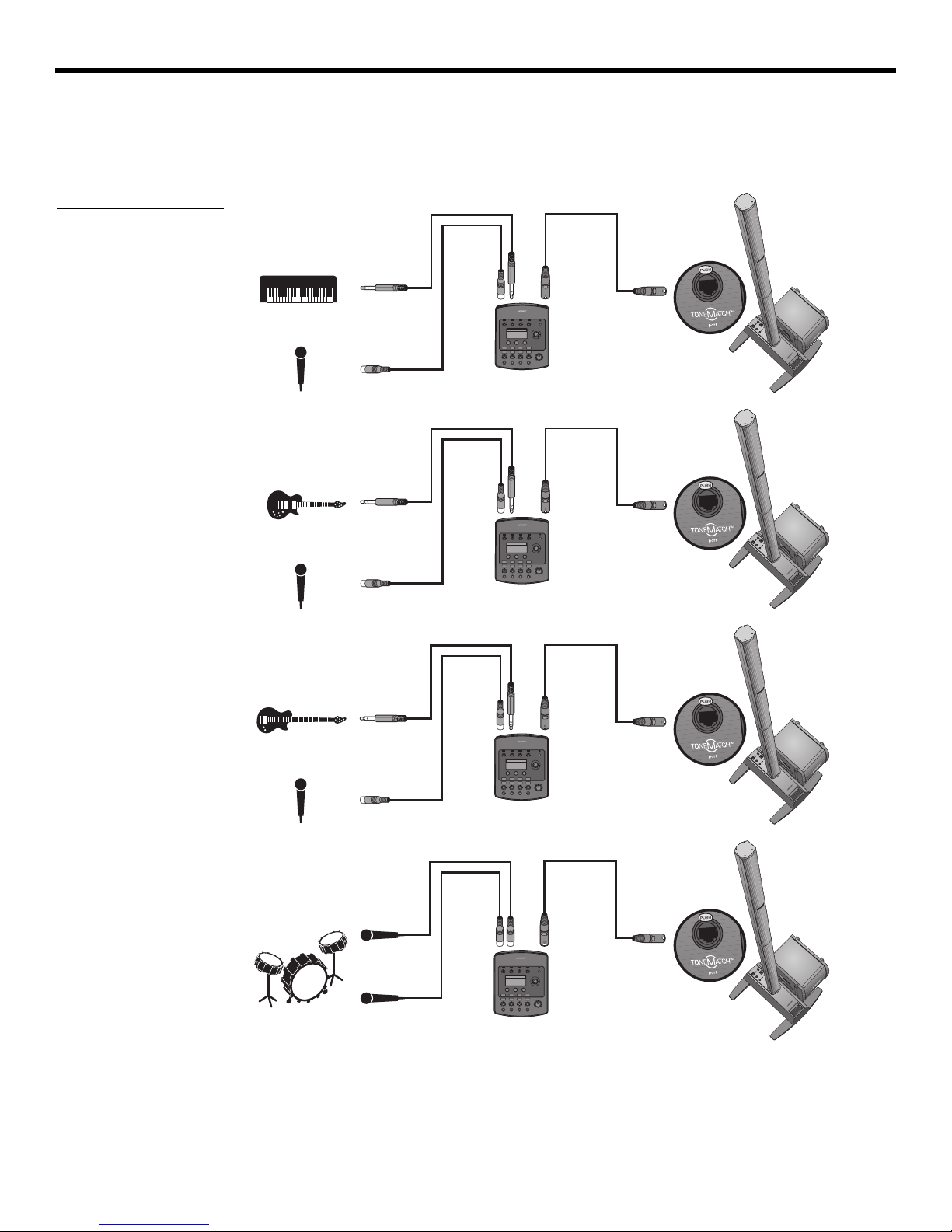
User scenarios
Figure 1
Single L1 model II system
with keyboard
There are many ways to set up and use this system with and without the T1 ToneMatch audio
engine. The following pages show examples of some typical user scenarios. When using the
T1 ToneMatch audio engine, refer to its owner’s guide for more information on setup and
operation.
Single musician
A solo musician might play a single instrument through the L1 model II system (Figure 1).
A solo musician also might play an instrument and use a microphone for vocals (Figure 2 on
page 18).
17
OPERATING INFORMATION
T1 ToneMatch®
audio engine
T1 ToneMatch
audio engine
Figure 2
Single L1® model II system
with guitar and microphone
EnglishDeutschFrançais DanskEspañolItalianoSvenska Nederlands DanskItalianoSvenska DeutschNederlands EnglishFrançais Español
Multiple musicians
In this scenario, a keyboard-guitar duo sings and plays through a single T1 ToneMatch audio
engine and an L1 model II system.
Figure 3
Single L1 model II system
with multiple instruments
and T1 ToneMatch audio
engine
18
English Deutsch FrançaisDansk Español Italiano SvenskaNederlandsDansk Italiano SvenskaDeutsch NederlandsEnglish FrançaisEspañol
T1 ToneMatch
audio engine
T1 ToneMatch
audio engine
T1 ToneMatch
audio engine
T1 ToneMatch
audio engine
Figure 4
Multiple L1 model II
systems, each with a T1
ToneMatch audio engine
OPERATING INFORMATION
Full band
A full band scenario is built around multiple T1 ToneMatch® audio engines and L1® model II
systems. Each musician plays and sings through a single T1 ToneMatch audio engine and L1
model II system.
19
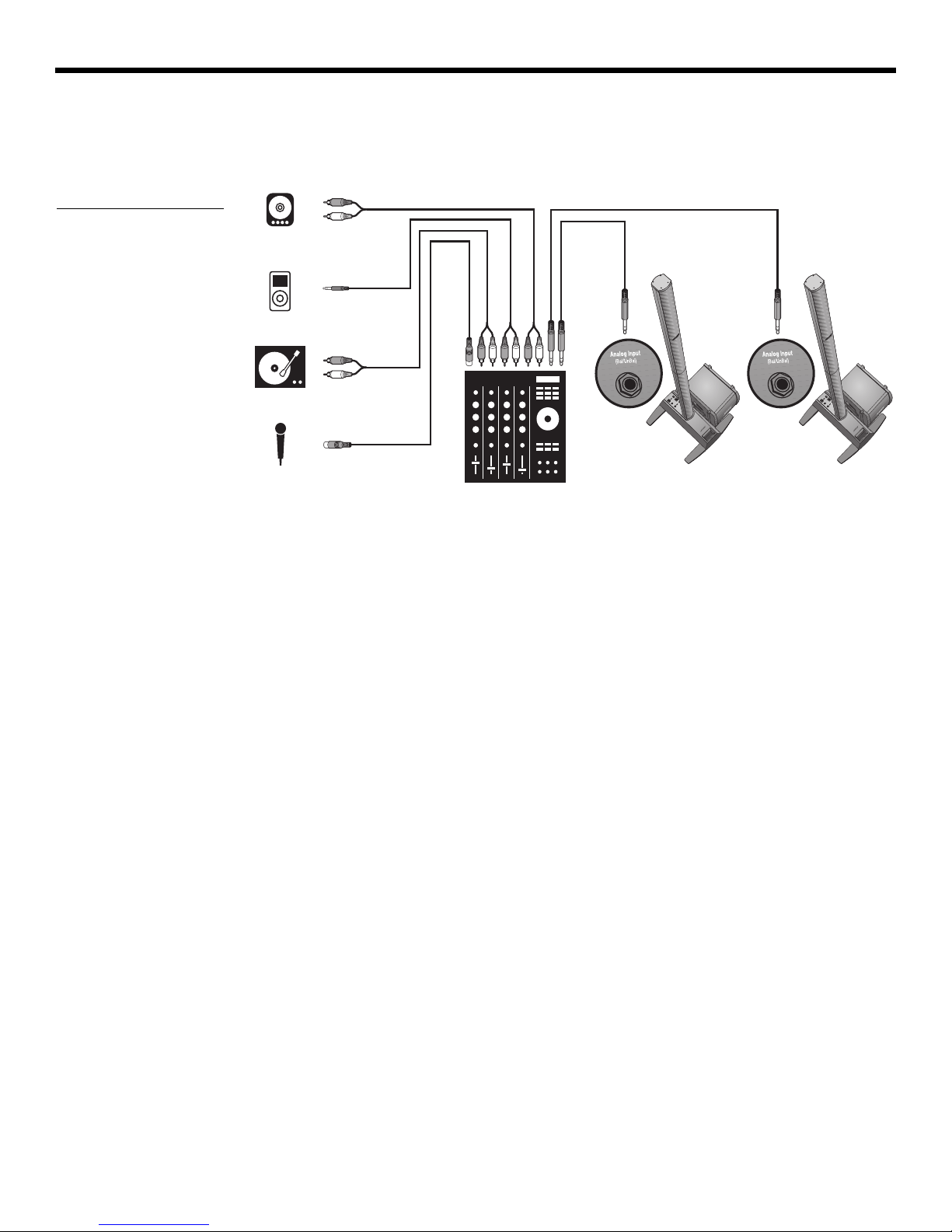
OPERATING INFORMATION
Figure 5
Two L1 model II systems, a
mixer, and input devices
EnglishDeutschFrançais DanskEspañolItalianoSvenska Nederlands DanskItalianoSvenska DeutschNederlands EnglishFrançais Español
DJ events
DJs use many types of input sources (CD player, turntable, MP3 player, etc.) plugged into a
mixer. In this scenario, two mixer outputs can be fed into two L1
sound.
®
model II systems for stereo
20

English Deutsch FrançaisDansk Español Italiano SvenskaNederlandsDansk Italiano SvenskaDeutsch NederlandsEnglish FrançaisEspañol
Caring for your product
Cleaning
• Clean the product enclosures using only a soft, dry cloth.
• Do not use any solvents, chemicals, or cleaning solutions containing alcohol, ammonia,
or abrasives.
• Do not use any sprays near the product or allow liquids to spill into any openings.
CARE AND MAINTENANCE
• If necessary
loudspeaker arrays.
Getting service
For additional help in solving problems, contact Bose Live Music Product and Technical
Support Team at (877) 335-2673 or visit our support area online at www.Bose.com/livesound.
Troubleshooting
If you experience problems while using this product, try the following solutions. If you still
can’t solve the problem, please call the Bose Live Music Product and Technical Support
Team direct at (877) 335-2673 to arrange for service.
Recommended troubleshooting tools
• Portable voltmeter • XLR and ¼" phone plug cables
• Cable tester • B1 bass module 4-wire cable
• AC outlet tester • Spare AC power cord
Problem What to do
Make sure you have power at the AC outlet. Try operating a lamp or other equipment
System is plugged in,
power switch is on, but
power LED is off
•
fr
om the same AC outlet or test the outlet using an AC outlet tester.
• Make sure the power stand’s power cord plug is fully inserted into the AC outlet.
, you may carefully vacuum
the grille of the L1® model II top and bottom
Power LED is on (green),
but no sound
Power LED is red while the
power stand is on
House circuit breaker
keeps tripping
• Make s
• Make sure the Trim level contro
• Make sure your instrument is plugged into the Analog Input jack.
onnect your instrument to the power stand using a different cable.
• C
• Plug your instrument into a different amplifier to make
•
Please call Bose Live Music Customer Support at (877) 335-2673 for assistance.
• If
more than one power stand is plugged into the same AC circuit, stagger the turn-on
times. Each power stand has an inrush current of about 32 amps when turned on.
• If you have more than three power stands plugged into a single 15 amp circuit, move
some systems to
playing at high volumes for long periods of time.
ure volume control is turned up on your instrument.
l is turned up on the power stand.
sure the instrument is working.
another AC circuit. Each power stand can draw 5 amps or more when
21
Venice_Care+Maint.fm 8/12

C
ARE AND MAINTENANCE
Problem What to do
EnglishDeutschFrançais DanskEspañolItalianoSvenska Nederlands DanskItalianoSvenska DeutschNederlands EnglishFrançais Español
With nothing plugged into
the power stand, a slight
hum or buzz is heard
B1 or B2 bass module is
plugged in
, but no bass
audio is heard
B1 or B2 bass module
unds out of
so
balance with
the system
No mid/high sounds heard
from the L1
®
model II
loudspeaker
Instrument or audio source
sounds dis
torted
Third-party-powered
subwoofer soun
when
connected to the
ds poor
Bass - Line Out connector
on the power stand
• Using an AC outlet tester, test the AC outlet that the power stand is plugged into for
r
eversed or open (hot, neutral, and/or ground) contacts.
• If using an extension cord, make sure that the cord is also tested as above.
• Make sure you are using the included 4-wire bass module cable.
• Make sure the bass module cable is plugged into the Ba
ss Module Out conn
ector and
the cable plug is fully engaged in the connector.
• Try a different 4-wire cable.
• If available, try a different bass module.
• Make sure your power stand firmware is up to date.
• Make sure you are using the bass module 4-wire cable included with the bass module
pa
ckage.
• Make sure that the bass module grille is facing forwar
d toward the musicians and
audience.
• Make sure the L1 model II top and bottom arrays are firmly seated in their connectors.
• Make sure connections are not bent or broken.
• Try cleaning the contacts on the loudspeaker top and bottom with electronic contact
spray clean
er.
• Make sure the Signal/Clip LED is not constantly red. If it is, lower the trim level.
• Try a different source or instrument.
• Try your source or instrument on another power stand.
• Unplug any Bose bass modules that may be connected to the power stand.
• The signal from the Ba
ss - L
ine Out may be too high for the powered subwoofer; try
attenuating the signal using commercially available direct boxes or in-line pad devices.
• Try different connections to the third-party-powered subwoofer
, such as balanced or
unbalanced cabling and/or a direct box.
• Check that the gain and input controls on the third-party-powered subwoofer are set
appropr
• If using a powered subwoofer with an adjustable crossover
iately.
, set the crossover to 180Hz.
B1 or B2 bass modules
powered by
a third-party
power amplifier and connected to the Ba
Out conne
ss - Line
ctor sounds
poor
Microphone is
encountering feedback
• Ensure that at least two B1 or B2 bass modules are directly connected to the Ba
Module Out
• Check the gain settings on the third-party power amplifier. The volume level of
modules powered by the power stand should be similar to the bass modules powered
by the external amplifier.
• Orient the microphone so that it is not pointing directly at its respective L1 model II top
d bot
an
• Try a different microphone.
• Try a different position for the loudspeaker and/or vocalist on stage.
• Increase the distance from the loudspeaker to the microphone.
• If using a vocal effects processor, make sure it is not contributing to the feedback
problem.
22
ss
connector on the power stand using a bass module 4-wire cable.
the bass
tom array loudspeaker.
Venice_Care+Maint.fm 8/12

English Deutsch FrançaisDansk Español Italiano SvenskaNederlandsDansk Italiano SvenskaDeutsch NederlandsEnglish FrançaisEspañol
Limited Warranty and Registration
C
ARE AND MAINTENANCE
Your product is covered by a limited transferable warranty. Details of the warranty are
provided with your product. Register your products online at www.Bose.com/register or
call (800) 905-1044. Failure to do so will not affect your warranty rights.
Accessories
Visit www.Bose.com/livesound, or call (800) 905-0886 for accessory information.
Technical Information
Mechanical
®
L1
model II power stand: 5''H x 10''W x 27''D
L1 model II top array: 43½''H x
L1 model II bottom array: 43½''H x
B1 bass module: 15''H x
B2 bass module: 23.4''H x
Dimensions Weight
23.7 lb
(12.8 cm x 26.2 cm x 69.2 cm)
3½''W x 4''D
0 cm x 9.0 cm x 10.5 cm)
(111.
3½''W x 4''D
0 cm x 9.0 cm x 10.5 cm)
(111.
10¼''W x 1
7¾''D
(38.0 cm x 26.0 cm x 45.0 cm)
13.31''W x 18.9''D
(59.4 cm x 33.8 cm x 48 cm)
(10.7 kg)
16.3 lb
(7.4 kg)
17.4 lb
(7.9 kg)
25.1 lb
(11.4 kg)
45 lb
(20.41 kg)
Electrical
•AC power rating:
100-120V
50/60Hz 500W (USA/Canada); 220-240V 50/60Hz 500W (Europe)
• Peak inrush current:
32A @ 120V
60Hz (USA/Canada); 61A @ 230V 50Hz (Europe)
Component Impedance
®
L1
model II top and bottom arrays: 4
B1 bass module: 8
B2 bass module: 4
Audio Input/Output
• T1 ToneMatch® port: DC output/data input Ethercon/RJ45 connector for a
T1 ToneMatch audio engine
• Analog Input: Line-level input channel for ¼" TRS phone plug
• Bass - Line Out: -4dBu (nominal), +9dBu (max.) (balanced TRS connection)
-10dBu (nominal), +3dBu (max.) (unbalanced TS connection)
• Bass Module Out: Neutrik NL4 output for one or two B1 bass modules, or for one B2
bass module
L1 and TONEMATCH are registered trademarks of Bose Corporation in the U.S. and other countries. All trademarks are the property
of their respective owners.
23
Venice_Care+Maint.fm 8/12
SIKKERHEDSINFORMATION
Bedes udfyldt, så du har oplysningerne til rådighed
Det er en god idé at notere dit systems serienumre her og på dit produktregistreringskort nu. Du kan registrere
dit produkt online på www.Bose.com/register eller ringe på tlf. (800) 905-1044. Hvis du ikke gør det, har det
ingen betydning for din garanti.
L1
®
model II-forstærkerfod ______________________________________________________________________
L1 model II-højttaler ____________________________________________________________________________
B2-basmodul __________________________________________________________________________________
Læs venligst denne brugervejledning
Tag dig tid til at følge denne brugervejledning omhyggeligt. Den vil hjælpe dig til at installere og betjene systemet
korrekt, så du kan drage nytte af dets avancerede funktioner. Gem denne brugervejledning, så du har den til
rådighed senere.
ADVARSEL:
ADVARSEL:
Overlad serviceringen til kvalificeret serv
Systemet må ikke udsættes for regn eller fugtighed af hensyn til risikoen for brand eller elektrisk stød.
Skil ikke systemet ad, med mindre du er kvalificeret hertil af hensyn til risikoen for elektrisk stød.
icepersonale.
Et lyn med pilehoved i en ligebenet trekant gør brugeren opmærksom på, at der i systemets kabinet kan
være uisoleret farlig spænding, der kan være så kraftig, at der er risiko for elektrisk stød.
EnglishDeutschFrançais DanskEspañolItalianoSvenska Nederlands DanskItalianoSvenska DeutschNederlands EnglishFrançais Español
Mærket med et udråbstegn i en ligesidet trekant skal gøre brugeren opmærksom på vigtige betjenings- og
v
edligeholdelsesinstruktioner i denne brugervejledning.
FORSI
FORSIGTIG:
overholdelse af lovbestemmelser samt systemets ydeevne over
FORSIGTIG:
FORSIGTIG:
Bemærk: Produktet skal anvendes inden døre. Det er hverken designet eller testet til udendørs brug, brug i
fritidskøretøjer eller i både.
Dette produkt overholder alle gældende EU-regler. Den komplette overensstemmelseserklæring kan findes på:
www.Bose.com/compliance.
GTIG:
Dette produkt skal tilsluttes en stikkontakt med en beskyttende jordforbindelse.
Undlad at foretage ændringer i systemet eller tilbehøret. Uautoriserede ændringer kan sætte sikkerheden,
styr.
Der må ikke anbringes åben ild som f.eks. tændte stearinlys på apparatet.
Hvis netstikket anvendes som afbryder, skal denne afbryder være let at betjene.
©2012 Bose Corporation. Gengivelse, ændring, distribution eller anden brug af dette dokument eller dele heraf er forbudt uden
forudgående skriftlig tilladelse.

English Deutsch FrançaisDansk Español Italiano SvenskaNederlandsDansk Italiano SvenskaDeutsch NederlandsEnglish FrançaisEspañol
Oplysninger om produkter, der genererer
elektrisk støj
BEMÆRK: Dette udstyr er testet og fundet i
overensstemmelse med grænserne for en digital Klasse
A-enhed i henhold til afsnit 15 i FCC-reglerne.
Hensigten med disse grænser er at sikre tilstrækkelig
beskyttelse mod skadelig interferens, når udstyret
anvendes i et kommercielt miljø. Dette udstyr genererer,
bruger og kan udstråle radiofrekvensenergi, og kan –
hvis det ikke installeres og bruges i overensstemmelse
med brugervejledningen – forårsage skadelig
interferens i forbindelse med radiokommunikation. Brug
af dette udstyr i en privat installation kan forårsage
skadelig interferens, og i så fald må brugeren få
udbedret interferensen for egen regning.
Ændringer eller modifikationer, der ikke udtrykkeligt er
godkendt af Bose Corporation, kan ophæve brugerens
ret til at betjene dette udstyr.
Dette produkt overholder den canadiske ICES-003
Klasse A-specifikation.
Initialt startstrømstød, når enheden tændes: 32 ampere
Inrush-strøm efter strømafbrydelse på 5 sekunder:
32 ampere
Dette produkt overholder alle EN55103-2
immunitetskrav for et E2 elektromagnetisk miljø.
VIGTIGE SIKKERHEDSINSTRUKTIONER
1. Læs disse instruktioner.
2. Gem disse instruktioner.
3. Ret dig efter alle advarsler.
4. Følg alle instruktioner.
5. Anvend ikke dette apparat i nærheden af vand.
6. Rengør kun med en tør klud.
7. Undgå at blokere ventilationsåbningerne.
Installer i overens
instruktioner.
8. Installer ikke produktet i nærheden af
varmekilder som f.eks. ra
komfurer eller andre apparater (herunder
forstærkere), der producerer varme.
9. Omgå ikke sikkerheden ved brug af et
ikke
-jordforbundet stik.
stikben, hvor det ene er bredere end det andet.
Et jordforbundet stik har to ben og et tredje
jordben. Det brede ben eller tredje ben er der
for din sikkerhed. Hvis det medfølgende stik
ikke passer i stikkontakten, skal du kontakte en
elektriker for at få stikkontakten udskiftet.
10. Beskyt netledningen mod at blive trådt på eller
klemt,
det sted, hvor den kommer ud af apparatet.
11. Brug kun tilslutningsudstyr/tilbehør, der er
ang
Brug kun apparatet sammen med en
12.
vogn, et stativ,
der er angivet af producenten eller
solgt sammen med apparatet. Når der
anvendes en vogn,
forsigtighed ved kørsel med vogn/apparat,
så det ikke vælter.
13. Afbryd strømmen til apparatet under tordenvejr,
eller når
14.
Overlad al servicering til kvalificeret
servicepersonale.
påkrævet, når apparatet på nogen måde er
beskadiget, hvis f.eks. netledningen eller
stikket er beskadiget, der er blevet spildt
væske, eller der er kommet objekter ind i
apparatet, hvis apparatet er blevet udsat for
regn eller fugt, ikke virker normalt eller er
blevet tabt.
især ved stikkene, st
ivet af producenten.
det står ubrugt i lang tid.
stemmelse med producentens
rer, varmeovne,
diato
Et polariseret stik har to
ikkontakter og på
et beslag eller et bord,
skal der udvises
Et serviceeftersyn er
15. Undgå at overbelaste stikkontakter,
fo
rlængerledninger
hensyn til risikoen for brand eller elektrisk stød.
16. Undgå, at genstande eller væske kommer ind i
pr
oduktet – de kan k
med farlig spænding eller kortslutte dele, hvilket kan
medføre brand eller elektrisk stød.
17. Se på bagbeklædningen angående mærkater,
der er r
1
8. Brug korrekte strømkilder – slut produktet til en
korrekt str
betjeningsvejledningen eller som markeret på produktet.
19. Apparatet må ikke udsættes for dryp eller
vandstænk,
f.eks. en vase – må ikke placeres på apparatet.
elevante for sikkerheden.
ømkilde som beskrevet i
og obje
eller indbyggede stik af
omme i berøring med steder
kter fyldt med vand – som
Venice_SafetyInstructions.fm 9/12

EnglishDeutschFrançais DanskEspañolItalianoSvenska Nederlands DanskItalianoSvenska DeutschNederlands EnglishFrançais Español
INDLEDNING 5
Velkommen . . . . . . . . . . . . . . . . . . . . . . . . . . . . . . . . . . . . . . . . . . . . . . . . . . . . . . . . . . . . . . . . . . . . . . . . . . . . . . . . . 5
Funktioner og fordele . . . . . . . . . . . . . . . . . . . . . . . . . . . . . . . . . . . . . . . . . . . . . . . . . . . . . . . . . .
Produktoversigt . . . . . . . . . . . . . . . . . . . . . . . . . . . . . . . . . . . . . . . . . . . . . . . . . . . . . . . . . . . .
Tilslutninger og betjeningsfunktioner . . . . . . . . . . . . . . . . . . . . . . . . . . . . . . . . . . . . . . . . . . . . . . . . . . .
. . . . . . . . . . . . . . . . 5
. . . . . . . . . . . . . . . . . . 6
. . . . . . . . . . . 7
OPSÆTNING AF SYSTEMET 8
Liste over dele . . . . . . . . . . . . . . . . . . . . . . . . . . . . . . . . . . . . . . . . . . . . . . . . . . . . . . . . . . . . . . . . . . . . . . . . . . . . . . . 8
Placering af dit system . . . . . . . . . . . . . . . . . . . . . . . . . . . . . . . . . . . . . . . . . . . . . . . . . . . . . . . . .
Opsætning af L1
®
model II-forstærkerfoden . . . . . . . . . . . . . . . . . . . . . . . . . . . . . . . . . . . . . . . . . . . . . . . . . . . . . . . . 10
Samling af L1 model II øverste og nederste højttalere . . . . . . . . . . . . . . . . . . . . . . . . . . . . . . . . . . . . . . . . . .
Tilslutning af vekselstrøm . . . . . . . . . . . . . . . . . . . . . . . . . . . . . . . . . . . . . . . . . . . . . . . . . . . . . . . . .
Tilslutning af B1-basmodulet . . . . . . . . . . . . . . . . . . . . . . . . . . . . . . . . . . . . . . . . . . . . . . . . . . . . . . .
Tilføjelse af en T1 ToneMatch
Tilføjelse af et ekstra B1-basmodul (ekstraudstyr) . . . . . . . . . . . . . . . . . . . . . . . . . . . . . . . . . . . . . . . . . . . .
Tilføjelse af en PackLite
®
-lydmotor (ekstraudstyr) . . . . . . . . . . . . . . . . . . . . . . . . . . . . . . . . . . . . . . . . . . . . . . . 13
®
-effektforstærker model A1 (ekstraudstyr) . . . . . . . . . . . . . . . . . . . . . . . . . . . . . . . . . . . . . . 15
Tilslutning af flere B1-basmoduler . . . . . . . . . . . . . . . . . . . . . . . . . . . . . . . . . . . . . . . . . . . . . . . . . . . . .
Tilslutning af et yderligere B2-modul . . . . . . . . . . . . . . . . . . . . . . . . . . . . . . . . . . . . . . . . . . . . . . . . . . .
. . . . . . . . . . . . . . . . 9
. . . . . . 10
. . . . . . . . . . . . . . 11
. . . . . . . . . . . . . 12
. . . . . . . . 14
. . . . . . 15
. . . . . . 16
BETJENINGSOPLYSNINGER 17
Indstilling af analogt indgangsniveau . . . . . . . . . . . . . . . . . . . . . . . . . . . . . . . . . . . . . . . . . . . . . . . . . . . . . . . . . . . . . . 17
Brug af en T1 ToneMatch
Brugerscenarier . . . . . . . . . . . . . . . . . . . . . . . . . . . . . . . . . . . . . . . . . . . . . . . . . . . . . . . . . . . .
Enkelt musiker . . . . . . . . . . . . . . . . . . . . . . . . . . . . . . . . . . . . . . . . . . . . . . . . . . . . . . . . . . . . .
Flere musikere . . . . . . . . . . . . . . . . . . . . . . . . . . . . . . . . . . . . . . . . . . . . . . . . . . . . . . . . . . . . .
Helt band . . . . . . . . . . . . . . . . . . . . . . . . . . . . . . . . . . . . . . . . . . . . . . . . . . . . . . . . . . . . . . . .
Dj-begivenheder . . . . . . . . . . . . . . . . . . . . . . . . . . . . . . . . . . . . . . . . . . . . . . . . . . . . . . . . . . . . . .
®
-lydmotor og en analog indgangskilde . . . . . . . . . . . . . . . . . . . . . . . . . . . . . . . . . . . . . . . 17
. . . . . . . . . . . . . . . . . . 17
. . . . . . . . . . . . . 17
. . . . . . . . . . . . . 18
. . . . . . . . . . . . . . 19
. . . . . . . . . . . 20
PLEJE OG VEDLIGEHOLDELSE 21
Vedligeholdelse af produktet . . . . . . . . . . . . . . . . . . . . . . . . . . . . . . . . . . . . . . . . . . . . . . . . . . . . . . . . . . . . . . . . . . . . 21
Rengøring . . . . . . . . . . . . . . . . . . . . . . . . . . . . . . . . . . . . . . . . . . . . . . . . . . . . . . . . . . . . . . . . .
Service . . . . . . . . . . . . . . . . . . . . . . . . . . . . . . . . . . . . . . . . . . . . . . . . . . . . . . . . . . . . . . . .
Fejlfinding . . . . . . . . . . . . . . . . . . . . . . . . . . . . . . . . . . . . . . . . . . . . . . . . . . . . . . . . . . . . . . . .
. . . . . . . . . . . . . . . . . . . 21
Begrænset garanti og registrering . . . . . . . . . . . . . . . . . . . . . . . . . . . . . . . . . . . . . . . . . . . . . . . . . . . . .
Tilbehør . . . . . . . . . . . . . . . . . . . . . . . . . . . . . . . . . . . . . . . . . . . . . . . . . . . . . . . . . . . . . . . . .
. . . . . . . . . . . . . . . . . . . 23
Tekniske oplysninger . . . . . . . . . . . . . . . . . . . . . . . . . . . . . . . . . . . . . . . . . . . . . . . . . . . . . . . . . . . .
Mekanisk . . . . . . . . . . . . . . . . . . . . . . . . . . . . . . . . . . . . . . . . . . . . . . . . . . . . . . . . . . . . . . . . .
Elektrisk . . . . . . . . . . . . . . . . . . . . . . . . . . . . . . . . . . . . . . . . . . . . . . . . . . . . . . . . . . . . . . . . .
Lydindgange/-udgange . . . . . . . . . . . . . . . . . . . . . . . . . . . . . . . . . . . . . . . . . . . . . . . . . . . . . . . . . . .
. . . . . . . . . . . . . 21
. . . . . . . . . . . . . . . . 21
. . . . . . . . . . . 23
. . . . . . . . . . . . . . 23
. . . . . . . . . . . . . 23
. . . . . . . . . . . . . . 23
. . . . . . . . 23
4

English Deutsch FrançaisDansk Español Italiano SvenskaNederlandsDansk Italiano SvenskaDeutsch NederlandsEnglish FrançaisEspañol
INDLEDNING
Velkommen
Tak, fordi du har købt et Bose® L1® model II-system med ToneMatch®-port. Dette system er
baseret på en revolutionerende teknologi, der gør det muligt at udnytte fordelene ved den
intime akustiske koncert til forstærkerunderstøttede optrædener.
Denne brugervejledning giver detaljer
L1 model II-system og forklarer, hvordan du tilslu
På www.Bose.com/livesound på intern
systemet, herunder tip, teknikker og ofte stillede spørgsmål.
Funktioner og fordele
• Du styrer lyden – På samme måde som når du ikke bruger forstærker, er det dig,
der styrer lyden. Du behøver ikke længere bekymre dig om, hvordan du lyder over for de
øvrige musi
• Hurtig og nem installation – L1 mo
af blot nogle minutter. Hermed er du fri for det tidskrævende og ofte frustrerende arbejde
med at installere et konventionelt lydudstyr korrekt.
• Væse
præstationen og fornøjelsen væsentligt, da du ikke længere skal anstrenge dig for at høre
dig selv og de andre musikere.
• Skab
spænding og sindsbevægelse, som musikelskere værdsætter.
• Du hører, hvad publikum hører – For
hører, og er derfor mindre tilbøjelige til at spille for højt.
• Musikken er naturligt dynamisk –
høres og nydes.
• Du tager dig bedre ud – Der er
ede installations-
ettet kan du finde yderligere oplysninger om brugen af
kere eller over for publikum, fordi du hører, hvad de hører.
del II-systemet er let at bære og kan installeres i løbet
ntlig præstationsforbedring – I forhold til
er spænding og følelser – Fo
rbedret musikerpræstation skaber den form for
første gang hører musikere, hvad deres publikum
Alt fra de blødeste til de mest intense passager kan
mindre udstyr på scenen og mere plads.
og betjeningsvejledninger til dit
tter udstyret til det.
traditionelt udstyr forbedres
• Lydgengivelse som aldrig før – Personer i publikum fo
spænding, der opstår ved at høre den nøjagtige gengivelse af lyd fra hvert enkelt
instrument og ved at høre lyden af hvert enkelt instrument i dets position på scenen
(i modsætning til mono- eller selv s
hørt ved en forstærker-understøttet optræden.
tereomix
af alle instrumenter), ikke ligner noget, de har
rtæller, at den klarhed og
5
Venice_Intro.fm 9/12
I
L1 model II øverste
og nederste
højttalere:
L1 model II-
forstærkerfod
L1 model II-system med ToneMatch-port
Ekstraudstyr
B1-basmodul
PackLiteeffektforstærker model A1
T1 ToneMatchlydmotor
Ekstra B1basmodul
B2-basmodul
B2-basmodul
NDLEDNING
Produktoversigt
Figur 1
L1 model II-system og
ekstraudstyr
EnglishDeutschFrançais DanskEspañolItalianoSvenska Nederlands DanskItalianoSvenska DeutschNederlands EnglishFrançais Español
L1® model II-systemet – med ToneMatch®-port består af forstærkerfoden, øverste og
nederste højttalere og et B1- eller B2-basmodul. Systemet leveres også med en polstret
taske til hver enkelt del.
For at udvide systemet og forbedre præstationen kan du tilføje:
• Et ekstra B1-basmodul til en basguitar, stortromme eller orgel. Hver forstærkerfod kan
forstærke op t
il to B1-basmoduler eller et enkelt B2-basmodul.
• En T1 ToneMatch-lydmotor til digital signalbehandling, yderligere indgange og
brugergræn
• En PackLite
sefladekontrol.
®
-forstærker model A1 til tilføjelse af op til to yderligere B1-basmoduler eller
yderligere et B2-basmodul til dit system.
Du finder en komplet liste over ekstraudstyr og tilbehør på www.Bose.com/livesound.
6
Venice_Intro.fm 9/12
English Deutsch FrançaisDansk Español Italiano SvenskaNederlandsDansk Italiano SvenskaDeutsch NederlandsEnglish FrançaisEspañol
Hovedafbryder
Tænder og slukker
systemet.
AC Mains
Indgangsstik
til strømforsyning.
Bass - Line Out
Post-DSP bassignaludgang.
Passer til et ¼” TRS-telefonkabel.
Benyttes til at drive en PackLite
®
forstærker.
Bass Module Out
Basudgangssignal for at drive et B2eller to B1-basmoduler. Passer til et
4-leder basmodulkabel.
Trim
Justerer det analoge
indgangssignals niveau.
Ton eM atc h
®
-port
Digital lyd- og
strømforbindelse til
ekstraudstyret T1
ToneMatch-lydmotor.
Passer til det medfølgende
To ne M at ch - ka b el .
Analog Input
En analog linjeniveauindgang.
Passer til et ¼” TRS-telefonkabel.
Benyttes til et instrument eller en
anden lydkilde.
Signal/Clip-lysdiode
Angiver status for det analoge
indgangssignal.
Grøn = normal indgang
Gul = indgang nærmer sig forvrængning
Rød = indgangsforvrængning
Power/Fault-lysdiode
Angiver status.
Blå = systemet er tændt
Rød = systemfejl
Tilslutninger og betjeningsfunktioner
Toppanelet på effektforstærkeren er udstyret med systemtilslutninger og betjeningsknapper
(Figur 2).
Figur 2
Toppanel på
effektforstærker
I
NDLEDNING
7
Venice_Intro.fm 9/12
Liste over dele
L1TM Model II System
with ToneMatchTM port
Owner’s Guide
www.Bose.com/musicians
Overdel
Underdel
B1
Bass Module
Installation Guide
Kasse med forstærkerfod
EnglishDeutschFrançais DanskEspañolItalianoSvenska Nederlands DanskItalianoSvenska DeutschNederlands EnglishFrançais Español
OPSÆTNING AF SYSTEMET
L1® model II-systemet leveres i tre kasser. Pak forsigtigt kasserne ud, og kontroller at du har
alle de dele, der er angivet på denne side.
ADVARSEL:
Opbevar plastikposerne utilgængeligt for børn for at undgå risikoen for kvælning.
Kasse med øverste og
nederste højttalere Kasse med B1- eller B2-basmodul
L1 model II-forstærkerfod
Transporttaske
Netledning
Demonstrations-cd
Hurtig installations- Brugervejledning
vejledning
L1 model II øverste og
nederste højttalere
Ta sk e r
B1- eller B2-basmodul
Låg
Basmodulkabel (4-leder)
Selvklæbende gummifødder
(kun til B2)
Produktregistreringskort
8
Brugervejledning til B1- eller
B2-basmodul
 Loading...