

BOSE L1 Schematic
L1® Compact
Portable Line Array System
Theory of Operation
©2009 Bose Corporation
Service Manual
Reference Number 318882-TOP Rev. 00
Electronic Copy Only

L1 Compact - Theory of Operation
General
This document refers to schematic revision 01 for both the I/O Board and PS & Amp board.
®
The L1
and all electronics, a removable T widdler
Twiddler Array to ear level when standing.
The electronics in the base are on two circuit boards: an I/O Board directly beneath the top
cover, and the PS & Amp Board which is mounted vertically on the back wall of the enclosure.
I/O Connectors
Compact comprises a Power Stand base unit that houses input and output connectors
TM
Array, and two extension sections used to raise the
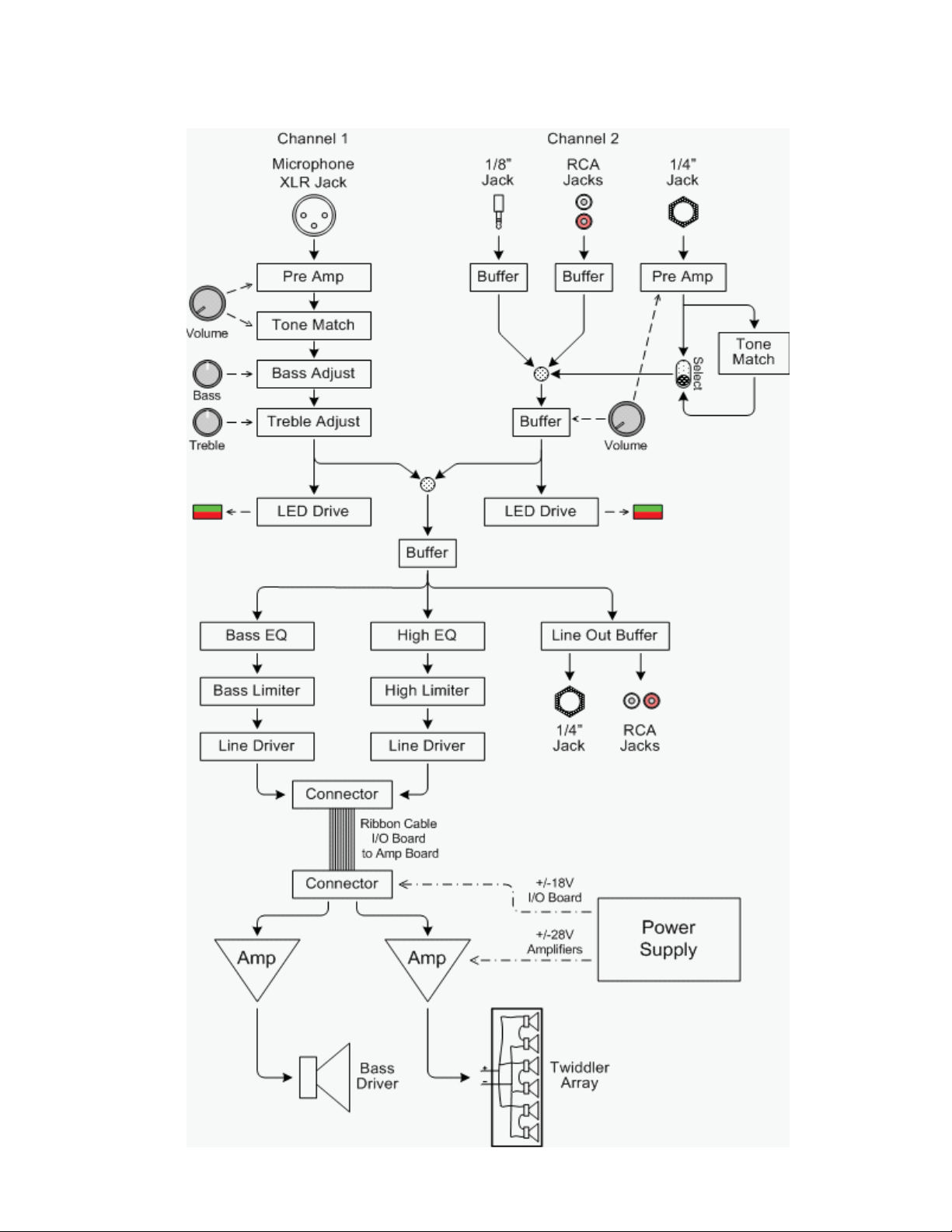
• AC mains input- IEC connector
• XRL Microphone Input Jack
• 1/8" Stereo Input Jack
• Two RCA Input Jacks
• ¼” Balanced Input Jack
• ¼” Line Out Jack
• Two RCA Line Out Jacks
Controls
• Power Switch - Switches the system on and off
• Mic V olume - Adjusts the Audio Output Level from the Microphone Input
• Mic Treble - Adjusts the T reble for the Microphone Audio Output
• Mic Bass - Adjust s the Bass for the Microphone Audio Output
• Channel 2 V olume - Adjusts the Audio Output Level from the Channel 2 Inputs:
- 1/8" Jack, RCA Jacks, or ¼” Jack.
Indicators
• Power Indicator - Indicates power status: Blue = system on.
• Signal/Clip Indicator - Ch1 (Mic) and Ch2 - Indicates the level of the Audio Output:
- Green = Normal. Red = Over Maximum Audio Level.
Power Supply
The L1 Compact Power supply is a Flyback switching supply based on Power Integrations
TOP258 which provides Under voltage, Over voltage, and Thermal Protection internally.
This produces four regulated DC Power Rails from the secondary: +28V and -28V for the amplifier (Philips / NXP TDA8920BTH) and +18V and -18V which are provided to the I/O board over
the 10 pin ribbon cable. These +/-18V rails are post regulated on the I/O board to +/-15V by
U315 & U316.
Diagrams – Pages 3 to 6
• L1 Compact Block Diagram
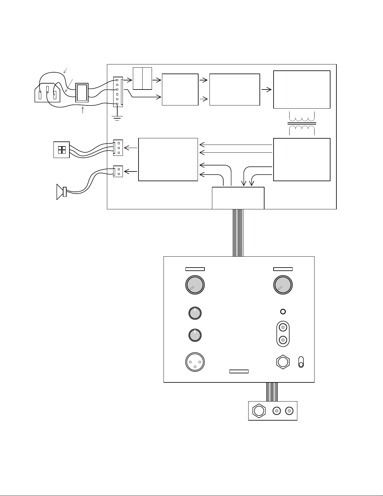
• L1 Compact PCB Layout
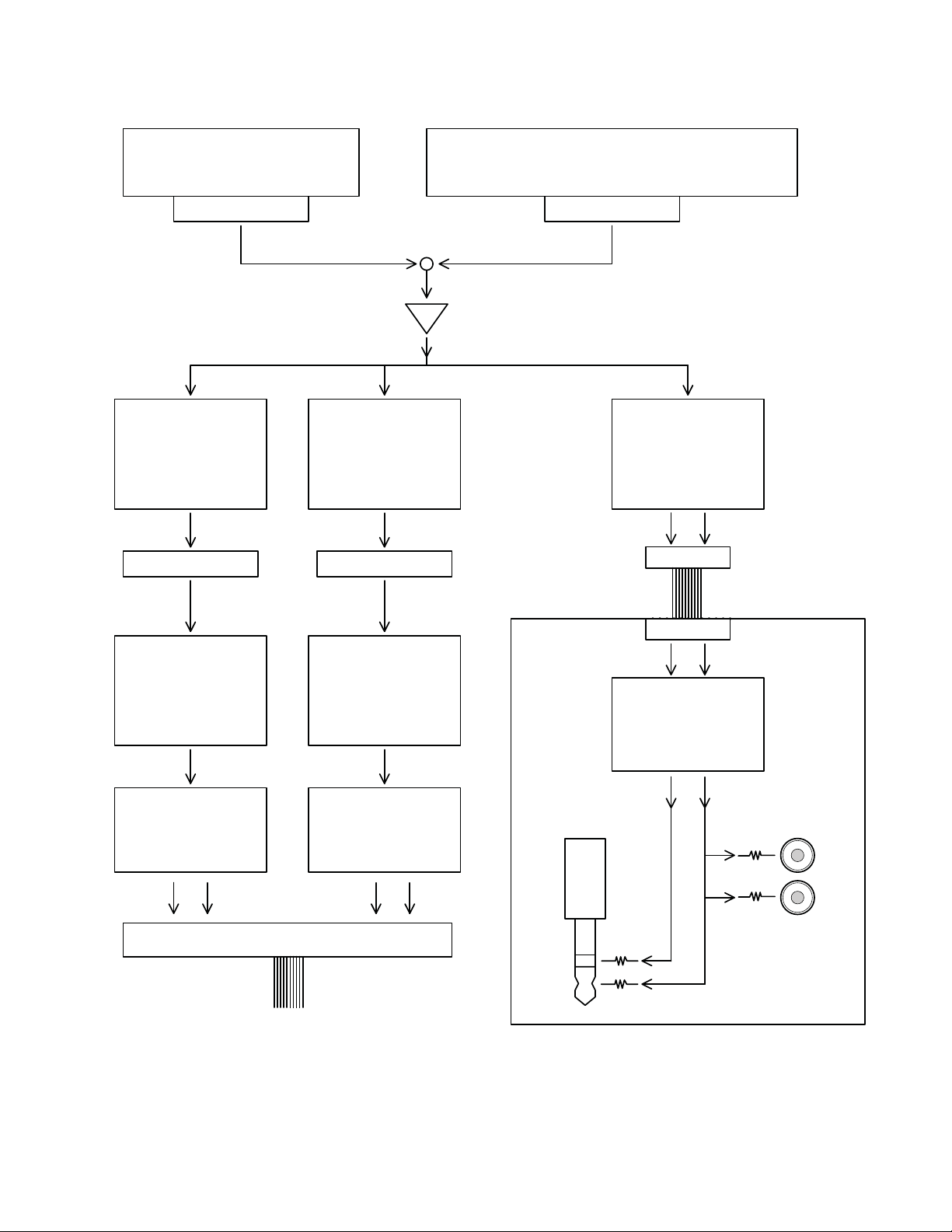
• L1 Compact I/O Board
• L1 Compact Channel 1 Input Section
• L1 Compact Channel 2 Input Section
2
L1 Compact - Theory of Operation
L1 Compact Power Stand Block Diagram
3
L1 Compact - Theory of Operation
AC Line
Filter
ON
OFF
IEC
AC IN
Brown = Line
Blue = Neut
Yellow /Green
= GND
Fuse
NTC
Bridge &
Main Caps
C1 & C3
Power
Switcher
TOP258 -
U1
Rectifiers
& Power Caps
Amplifier
TDA8920 BTH
+28V
-28V
I/O Board
Connector
+18V
-18V
Twiddler
Bass
Twiddler
Array
Bass
Driver
Bass
Mi crophone
Treble
Volum e
Volum e
1 2
Inputs
Line
Level
Ribbon
Cable
I/O Board
see next page
Line Out
Power
Power Supply & Amplifier Board
L1 Compact PCB Layout
4
L1 Compact - Theory of Operation
MIC Input & Pre-amp
see next page
Schematic Sheet 2
RCA Jacks
Bass EQ
U308A-B
U309A-B
J300J301
¼” Jack
(6MM)
Spark Gaps
SG701, -02, -03, -
04, -05
& EMI Filter
+
1/8", RCA, & 1/4” Inputs & Pre-amp
see next page
CH1_TONE CH2 Output
U300A
Line Ou tput Card
CN302A
CH1 & CH2 SUMMER
High EQ
U301A-B, U302A-B
U303A-B, U310B,
U306B, U304B
Line Output
Driver
U317A-B
+
-
+
-
+
-
High Limiter
U304A, U314B
U391A-B, U306A
Bass Limiter
U312A-B, U310A
U500A-B, U312B
High Output
to Amp
U313A, U307A
Bass Output
to Amp
U313B, U307B
Bass Audio High Audio
Schematic Sheet 3
CN300A
+
-
+
-
-
CN302B
Ribbon Cable to PS & Amp
L1 Compact Input / Output Board
5
L1 Compact - Theory of Operation
Microphone
Spark Gaps
SG100, SG101
& EMI Filter
Transistor Pre-Amp
Q101, Q 102, Q103
Q104, Q 105, Q106
& U100B
Mic Tone Match
U100A, U101A-B
U102A-B, U 103B
VR100B
J100
VR100A
CH1 Output
CH1 Output
Bass Adjust
U103A, U104A
Bass
VR101
Treble Adjust
U104B
VR101
Mic LED Driver
U106A-B, U107A-B
To CH1 & CH2
SUMMER
Schematic Sheet 1
Schematic Sheet 2
CH1_TONE
Volume
Treble
1/8” Jack
(3.5MM)
Spark Gaps
SG801, -02, -03
& EMI Filter
Pre Amp
U50 1A- B
U502B
U204B
VR200A
J801
VR200B
CH2 Output
3.5MM Jack Input Card
U305A
Schematic Sheet 1
CN308B
CN308A
RCA Jacks
Spark Gaps
SG202, -03, -04
& EMI Filter
U305B
J200
J202
1/4” Jack
(6MM)
Spark Gaps
SG200, SG201
& EMI Filter
Tone Match
U201A-B, U202A-B
Select
U20 7
Ch 2 Volume
U205A, U204A
Volume
+
-
+
-
Mic LED Driver
U300B, U205B,
U20 6A- B
Schematic Sheet 2
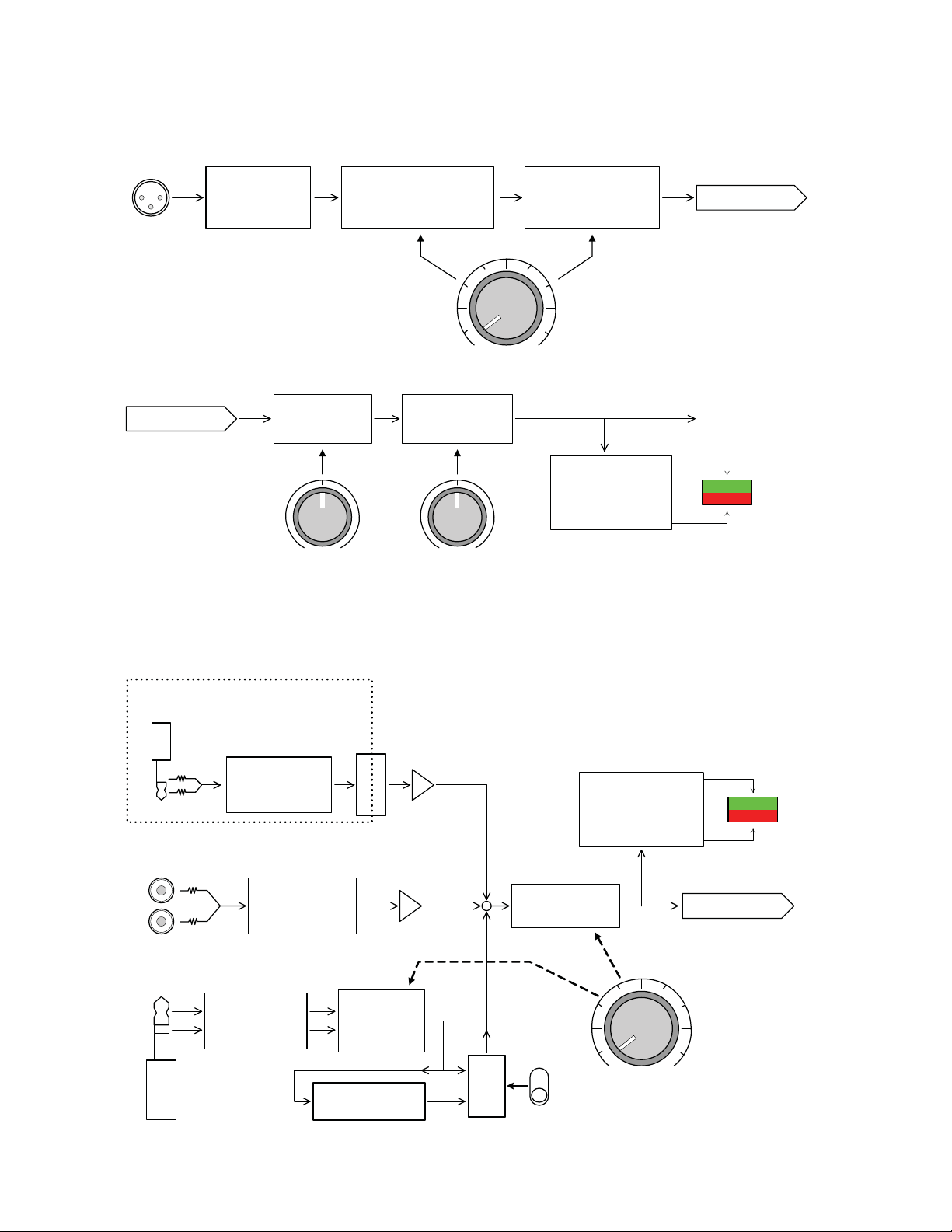
L1 Compact Channel 1 (Microphone) Input Section
L1 Compact Channel 2 Input Section
6
 Loading...