

BOSE ACOUSTIC Schematic

OVERVIEW
This service manual contains performance specifications, part lists and the test and repair procedures for the
Bose® Acoustic Wave® Cannon™ System II (AWCS II). The following is a brief product description.
The AWCS II is an actively equalized low frequency (25 - 125 Hz) loudspeaker system. The AWCS II
loudspeaker uses a high power 12" woofer (same as the Bose Panaray® 502® B Acoustimass® bass
enclosure) which is installed into a pipe-shaped enclosure made of custom-extruded PVC plastic pipe.
The AWCS II must be used with a Bose system controller and OC-1 option card for the proper equalization
and overload protection. Refer to the ACWS II Owner's Guide for basic system configurations. Consult the
owner's guide for a specific system controller for details concerning its operation and installation.
PROPRIETARY INFORMATION
This document contains proprietary information of BOSE® Corporation which is being furnished
only for the purpose of servicing the identified BOSE product by an authorized BOSE service
center or owner of the BOSE product, and shall not be reproduced or used for any other
purpose.
1
CANNON™ SYSTEM II TEST PROCEDURES
NOTES: Some of the test procedures may require the user to partially disassemble the unit. Refer to the
Disassembly/Assembly Procedures section for specific instructions.
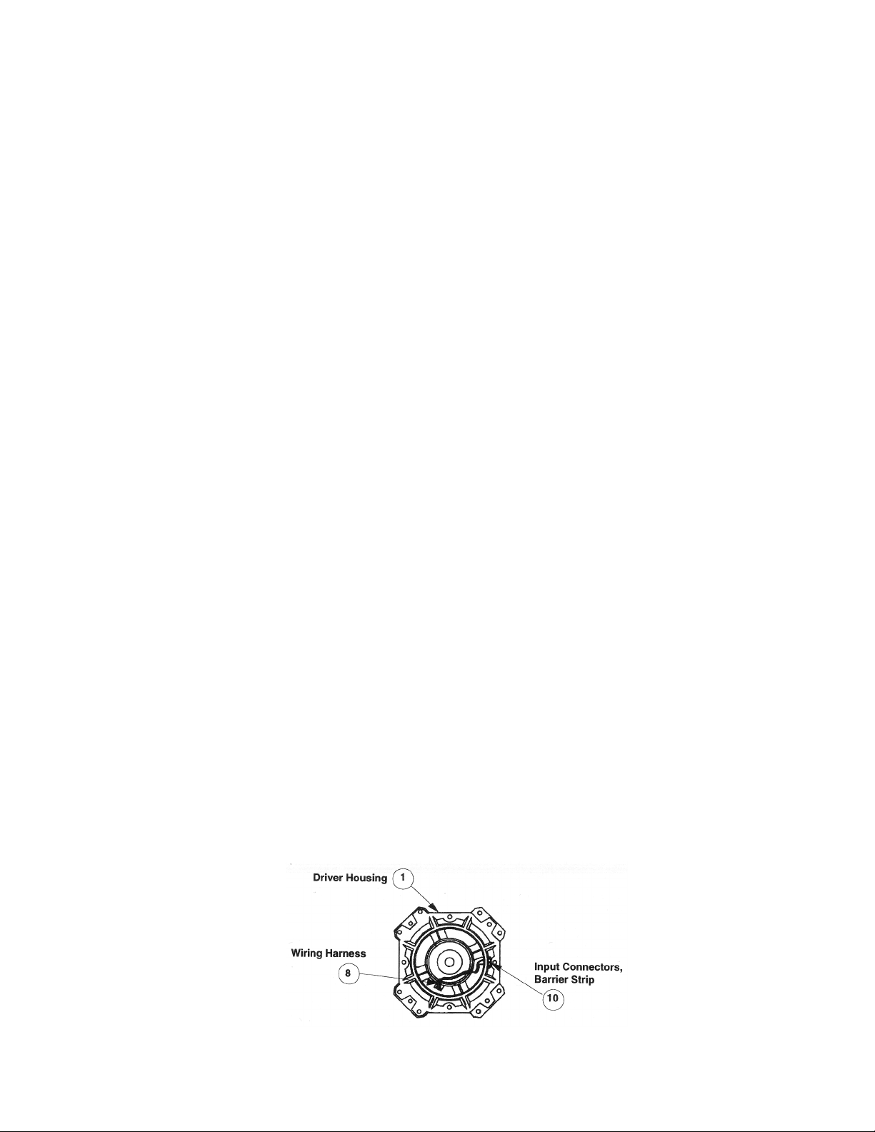
1. Woofer Rub and Tick Test
Connect a signal generator to a power amplifier. Adjust the generator frequency to 10 Hz and the amplifier
output to 5 Vrms. Connect the amplifier output to the driver's input terminals. The input terminals are
molded in the driver housing near the barrier strip. Refer to Figure 1.
No extraneous noises such as rubbing, scraping or ticking should be heard.
2. Air Leak Test
Plug the end the of the barrel.
Adjust the oscillator frequency to 10 Hz and the amplifier output to 5 Vrms. Apply the signal to the
positive and negative inputs of the speaker. For at least 5 seconds, listen for air leaks around the driver
basket edge, driver housing seal area, barrier strip, or the driver's dustcap and cone surround.
Repair leaks around the driver by removing the driver and replacing the gasket under the driver flange.
3. Phase Test
Set a DC power supply to 8 volts. Connect the positive (+) supply lead to the positive (+) speaker input
terminal and the negative (-) supply lead to the negative (-) speaker input terminal. The woofer cone should
move outward.
NOTE: Supply voltage should only be momentarily applied to the speaker input terminals to avoid possible
damage to the speaker.
4. Sweep Test
Apply a 15 Vrms, 25 Hz signal to the speaker's input connectors. Sweep the oscillator from 25 Hz to 125
kHz, there should not be any buzzes, rattles or extraneous noise.
There should not be any buzzes or rattles from within the speaker cabinet. Redress any wire or
component that buzzes.
Figure 1. Wiring Harness and Input Connectors
2
DISASSEMBLY/ ASSEMBLY PROCEDURES
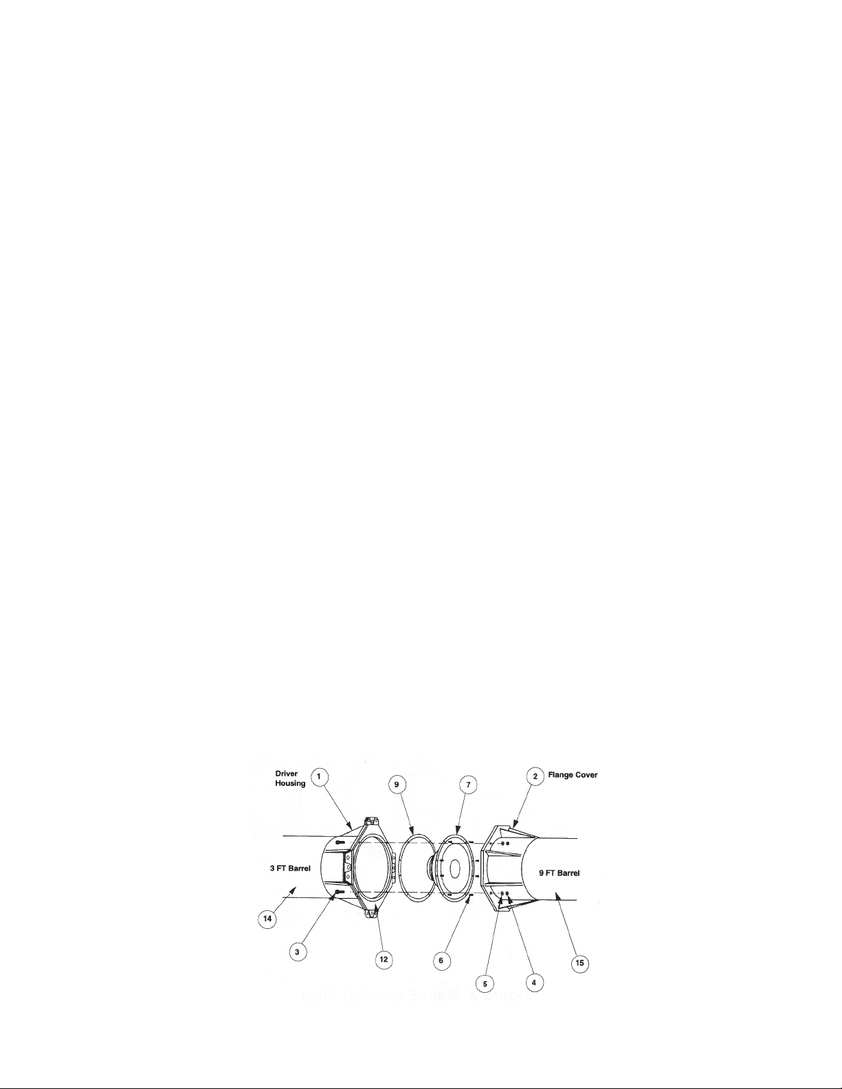
NOTE: Numbers in parentheses represent the item callouts in Figures 1 and 2.
1. Driver Removal (Refer to Figures 1 and 2)
Note: Use Step 1.1 to disassemble the short 3ft driver barrel (14) from the 9ft barrel (15).
1.1 Use a 3/8" hex-head wrench to remove four flange bolts (3), locknuts (4) and washers (5) that holds
the driver housing (1) and flange cover (2) together.
1.2 Use a hex-head wrench to remove the eight bolts (6) that mount the driver (7) to the driver housing.
1.3 Use a flat-head screwdriver to pry the driver out from the driver housing. Do not let the driver fall out
beyond the distance of the wiring harness (8). To remove the risk of damage to the driver, it's advisable to
have two people perform this step.
1.4 Remove the two connectors (part of the wiring harness (8)) from the driver's terminals.
1.5 Remove the driver from the housing.
2. Driver Replacement (Refer to Figures 1 and 2)
2.1 Place the driver gasket (9) into the driver housing (1). Align the screw holes in the gasket with the
screw holes of the driver housing.
2.2 Connect the two connectors from the wiring harness (8) to the terminals of the new driver (7).
2.3 Bolt the driver into the driver housing by tightening eight bolts (6) with a hex-head wrench.
2.4 Assemble the 3ft driver barrel (14) and the 9ft barrel (15) by matching up the interlocking tabs on the
driver housing (1) and flange cover (2).
2.5 Tighten four flange bolts (3), locknuts (4) and washers (5) with a 3/8" hex-head wrench.
Figure 2. Cannon Assembly
3
 Loading...