

Page 1
Owner’s Manual
Page 2

Table of Contents
»- -
t
1. Introduction
II. Unpacking Instructions
III. The 901 Series III Loudspeaker System
A. Design Features
B. Technotogical innovations
4
IV. Installation
A. Placing the Speakers
B. Connecting the Speakers
1 Wire Selection
2 Phasing/Wiring
3 Fusing
C. Connecting the Equalizer
1 Using li)e Tape Monitor Circuit
2. Using Separate Components: Connecting Between the Preamp and the Amplilier
3 Using the Preamp Oul/Main in Circuit
4 Using Four Channel Equipment
Connecting Other Equipment
A, Tape Recorders
B. Headphones and Conventional Speakers
14
VI. Living with your BOSE 901 Speakers 16
A Adjusting Your Equalizer Controls
B Speaker Placement
C. Room Acoustics
VII. Technical Information
A. Specificalions
B Voltage Conversion
C in Case of Difficulty
0 Care and Maintenance
/
18
VIII. Warranty 20
3
3
6
l9/(> UOSK Cufpuralion Covered by palenl rights issued and ponding
Page 3
I. Introduction
Thank you for purchasing the BOSE 901 Series III Direct/Reflecting* speaker system. The listening enjoyment you will experience
is the culmination of many years of research dedicated to the art
of bringing superb musical reproduction into the home.
The BOSE 901 Series III. with Its high proportion of reflected sound,
nine full-range drivers, and electronic active equalization, is in
stalled. connected, and operated differently than conventional
loudspeakers The detailed installation and placement instructions
found in this manual are important. PLEASE TAKE THE TIME TO
READ THESE INSTRUCTIONS CAREFULLY With proper installa
tion. you will be rewarded with the unique listening pleasure pro
vided by your 901's.
II. Unpacking Instructions
The 901 Series III speaker system is packed in two cartons marked
"Part 1 and "Part 2. The active equalizer is found in the carton
filler material along with the "Part 1" speaker. Unpack both cartons
carefully Save the cartons and packing material for possible use
later. If either of the speakers has visible damage when unpacked,
do not place the damaged speaker(s) in operation Repack the
speaker(s) in the original carton with the complete packing mater
ial and notify your dealer immediately
Page 4

• t
III. The 901 Series III Loudspeaker System
A. DESIGN FEATURES
1. Correct Balance ot Reflected and Direct Sound
The BOSE 901 Series III is designed to use your listening
room walls to simulate the reflective properties of the much
larger stage wall found behind the instruments of a live per
formance. The 901 Series ill uses nine drivers, eight directed
towards the back wall, and one driver directed into the lis
tening area, thus recreating the proportion of reflected to
direct sound experienced in the larger environment of a live
performance.
2. Active Equalization
The active equalizer electronically corrects for any deviation
in frequency response caused by the mechanical design
constraints of the speaker. This Is accomplished by elec
tronically ‘contouring' the preamplifier signal; thus, the
entire system radiates the correct balance of total acoustic
power at every frequency.
3. Multiple Full-Range Drivers
To accurately reproduce the timbre of every musical instru
ment, a loudspeaker system must reproduce every portion
ol the frequency spectrum in correct balance; however,
every loudspeaker has many inherent resonances that cause
its response in certain portions of the frequency range to be
reduced or accentuated
The 901 system utilizes two unusual physical phenomena
called “resonance splitting ' (ihe acoustically coupled drivers
force the resonances to "splir to different frequencies, thus
smoothing the response) and “response averaging” (any
driver response irregularity is “averaged" with the other
drivers and becomes an insignificant ‘4 of the total power).
B. TECHNOLOGICALINNOVATIONS
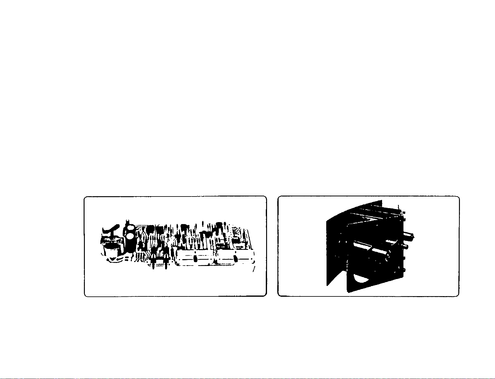
1. The New Full-Range High-Performance Driver
In the 901 Series III driver, a combination of technological
advances make possible its outstanding performance;
• A highly efficient magnetic structure with all parts as
sembled to precise tolerances to provide maximum mag
netic field energy.
• An aluminum helical voice coil, providing better utilization
of magnetic energy,
• A now cone and suspension for smoother, more controlled
frequency response and lower distortion.
• An injection molded frame, eliminating distortion of the
magnetic field (caused by steel frames) and improving
precision in assembly.
The combination of the helical voice coil and precision as
sembly means that a 15 watt amplifier will produce the loud
ness that required a 50 watt amplifier with the Bose 901
Series II.
Page 5
2. The New Active Equalizer
The original 901 introduced the concept of active equaliza
tion to home loudspeaker systems It demonstrated the
fundamental performance advantages of incorporating
equalization as a part of the loudspeaker system design
The 901 Series III realizes additional advaniagcs of active
equalization with three new equalizer features:
• More precise equalization of the audible sound spectrum
made possible by significantly more complex equalization
circuits
• Additional control flexibilily. permitting optimum speaker
performance in a wide range of room positions (see SEC
TION VI).
• Control of response of the speaker beyond the audible
range This precise contouring of response at frequencies
inaudible to the human ear allows the drivers and enclos
ure to be designed for optimum performance character
istics.
3. The Acouslic Matrix"^ Enclosure
The enclosure of the 901 Series III is designed specifically
to work with nine full-range matched drivers in combination
with the active equalizer.
Tiie enclosure Incorporates three Reactive Air Columns (one
for the front driver and one for each group of four drivers on
the rear panels) The purpose of the air columns is to provide
reactiveair loading toreduce the motion required of the driver
cones at extremely low frequencies, thus allowing maximum
efficiency with lowdistorlion.
Additionally, the enclosure partially isolates the acoustic
pressure at each driver from other drivers to permit it to
operate properly through the frequency range where reac
tive loading occurs.
Page 6
IV. Installation
Your 901 Series 111 speaker system consists of three parts; two
speakers (marked "Part 1" and "Part 2") and an electronic Active
Equalizer packed in the "Part 1" container. Installation consists of
three steps; 1) placing your speakers for best sound. 2) connecting
Ihe speaker to your amplifying equipment, and 3) connecting Uie
equalizer to your amplifying equipment.
A. PLACING THE SPEAKERS
Unlike conventional speakers. Ihe 901 Series III functions with
the acoustics of your listening room, simulating the spatial char
acteristics of the larger environments associated with live per
formances This important advantage allows considerable free
dom of placement and produces an unusually large "best listen
ing area.” Outstanding performance can be obtained under a
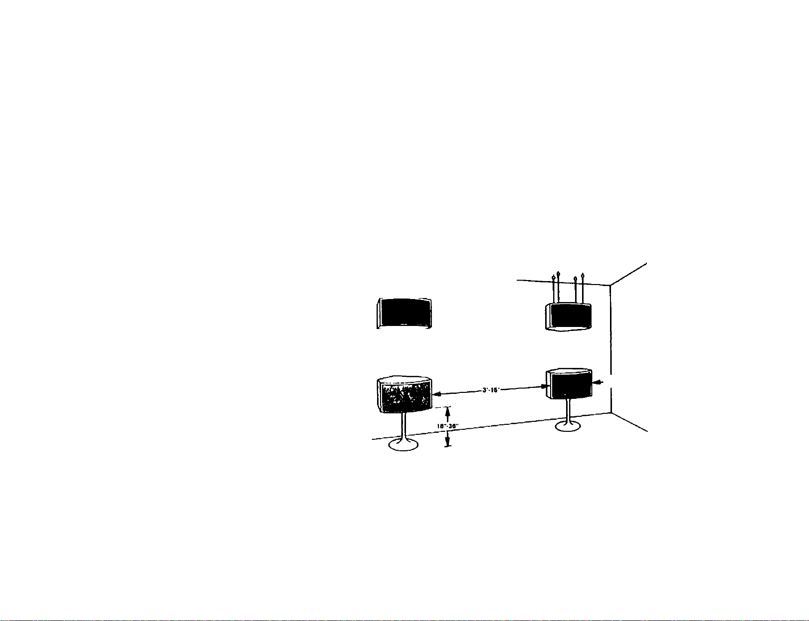
wide variety of placement positions. (See Figure 2 )
The following guidelines in placing the speaker cabinets will
help you obtain the best performance The basic idea is to pro
vide space to allow the sound to develop around the speaker
system.
1 The angled grille panels found on the enclosure are the rear
face of the 901 speaker (see Figure 1) Point this portion of
Ihe speaker toward the reflecting wall (the wall behind the
speaker) The point of the "V" should be between 12" and 24"
from the reflecting wall. Best results will be obtained with
the speakers placed between 12" to 18" from the reflecting
wall
2. Speakers should be placed at least 18" above the floor or
below the ceiling (see Figure 1). Distances closer to the
coiling or floor restrict the reflected sound energy.
t
3 The speakers should be at least 18" from a side wall or open
ing into an adjacent room (Suggested distances are 3' to 5'.)
Large objects (such as furniture) should be at least 24" away
from the side of the speaker.
4 Best results will be obtained with the speakers spaced apart
6' to 10'; however, separation as small as 3' or as great as 15'
will give excellent results in most rooms.
if you have not decided where to place your speakers and
would like more information. SECTION VI (LIVING WITH
YOUR BOSE 901 SPEAKERS) provides several additional sug
gestions for speaker placement
« A
I
if’W
J.
REFLECTING
WALL
Figure 1
Page 7

Page 8

Installafion
B. CONNECTING THE SPEAKERS
1. Wire Selection
If the wire used to connect the speakers to your power am
plifier has too much resistance, audible coloration of the
sound and loss of power can result, The table below summar
izes maximum wire lengths for 18*. 16*. and 14-gauge, twoconductor. stranded copper wire for use with one or two
pairs of BOSE 901 loudspeakers
TABLE 1
RECOMMENDED CONNECTION WIREf
Wire Length
One Pair
of 901s
27 feet
Wire Length
Two Pairs
of 901s
Type of Speaker
Hook-Up Wire
13 feet 18-gauge zipcord
(or two-conductor wire)
42 feet
21 feet 16-gauge two-conductor
wire
67 feet
34 feet
14-gauge two-conductor
wire
In most inslances. copper zip-cord, readily available at most
electrical and hardware stores, can be used for speaker con
nection. This wire usually lias a ribbed iine(s) along one
side of the insulation so that each wire can be identified for
proper phasing of your speaker system.
t IlHfwircloiKjiluiijHnvnin i.il)lt‘ 1 wuit'i4ili:iAiluionlliel).i^sol >j iiiixiinuiii.iuUililu
uiloralHMiol ¿Obtlli I iXIowitHj llH;(juKloliMU!>|)ioviik.-(J. IIil* m(XiU)>b(:umin(jli:4ciHX
wiU lHjun.iL)lc‘lo(tLiL4.i iiiIttMliicoil l>v llie sixsiKor wiiu Mcc,! hslunvfb
Will ncK (luliUMny с1кл:1 cvun il wiiuk.‘nyihbJfuiiK.ru<isc4jl>yasniuUia^SU%
2. Phasing/Wiring
It is important that the amplifier connections for both 901
speaker systems be identical (see Figure 3) so that both
speakers work together (in phase).
a. Start with the speaker marked “Part 1."
b. Place it on the left side of your room facing the speaker
system.
c. Locate the **+" and terminals on the bottom of the
speaker
d. Using the speaker wire (which is marked to distinguish
one conductor from the other), connect the "Part 1"
speaker terminal marked to the terminal marked
"com." "negative." or "minus" on the left channel ampli
fier output. (When connecting the 901 Series III loud
speakers to your amplifier, if there is a choice of impe
dances on the amplifier output, use the terminal marked
"8" or "8 ohms." If two pairs of 901 Series III loudspeak
ers are being connected, the terminal marked "4" or "4
ohms" on the receiver or amplifier should be used.)tt
tfNolu Wl№n ofMMuitrKj your 90ls hi sleiuo. only one equah^er is required II addi
liiNuii pairs ol 001s die used, ihey can bu purchased willroul itie equalizer these
s^X'aKursaiu suklas' ackl on" pairs and can Lx* connected as extension speakers or
usedinadJilion to II te hrsi pair ol speakers
WlxtiuHiiHxliiKj two i^uisul out siieukeis lo your ertinpinuni who ilio siieakers in
IxiiaHel MKisl luxiiily manulaciureJ leceivursor ain()litiers wi^l laxirule iwu pans ul
00 Is wiiorl HI llns mtinix*r I luwiiver. il your receiver or arnphlxi is iKil i:j|xiI)Iu ol
4 ohm otx'iaUon wilh two [x»is ol 901s. wire Hie speakers in series Contact your
dealer il any luMIxf assislaix.ers required
8
Page 9

e. Connect theterminal on the left speaker to the termi
nal marked "pos.” "positive." or "plus” on the left channel
output of the amplifier or receiver.
NOTE; Use only the terminals marked " k" and The
terminal marked Is intended for future electronic de
velopments and should not be used with conventional
amplifying eouipment.
f Place the speaker marked "Part 2" on the right side of the
room and repeat the connection procedure for the right
amplifier channel.
g If you are using an amplifier rated at over 100 waits rms
per channel, fuse your speakers as outlined in SECTION 3
3. Fusing
Any loudspeaker is subject todamage if the amplifier powering
it should fail. The use of a fast-acting fuse in series with each
speakerwill minimize the possibility of ser ious damage toyour
speaker.
For amplifiers rated at under 100 watts rms per channel, no
fusing is required. Amplifiers rated over 100 watts per channel
should be fused with a fast-blow. 3-ampfuse.
Purchase fuseholders and the appropriate fast-acting fuses
Connect the fuseholders in series with the positive wire going
to each speaker, placing the fuse in an easily accessible
location.
BOSE Corporation recommends the use of the Buss AGC
SeriesortheLittlefuseAGSeriesasspeakerfuses
Page 10

Installation
C. CONNECTING THE EQUALIZER
IT IS MOST IMPORTANT THAT YOU FOLLOW THESE IN
STRUCTIONS FOR OPTIMUM PERFORMANCE OF YOUR
901 SERIES III SPEAKER SYSTEM
1. UsingtheTapeMonitorCircuit
The connection methods described in this section can be
used with virtually all integrated amplifiers, preamplifiers, and
receivers ^ Using the tape monitor circuil has two advantages;
When using conventional loudspeakers or headphones, the
tape monitor circuit allows disconnection of the Active Equal
izer by turning off the tape monitor switch on your control am
plifier; this is important because conventional speakers and
headphones should not be used with the Active Equalizer
(See SECTION V.) Also, optimum system noise performance
is obtained when connecting the equalizer in the tape moni
tor circuitry
When using this procedure, you should realize that the 901
equalizer is being connected to your equipment as if it were a
tape recorder, using the tape monitor connections of your
control amplifier.
NOTE: Check your control equipment to determine if your
unit has any additional switching flexibility. Some recently in
troduced units now feature switching facilities called Tape
Monitor 3. External Equalizer/Processing. or Noise Reduc
tion Connections. The equalizer can be connected to these
terminals allowing greater system flexibility if required.
f hmuki'aMwici liimc.Jiituf. we areyoitKj lo lelei U)i¿l irf ll»ese vaiKius coiii|A»nunis
dSlIw'coMMol iiini.ililiei"
Referring to FIGURE 4. connect the Active Equalizer ac
cording to the following instructions;
a. Turn off all power to your high-fidelity system,
b If you have a tape recorder, disconnect it from your con
trol amplifier.
(Instructions in SECTION V will tell you how to reconnect
your tape recorder to the system after the equalizer has
been installed.)
c. Using one of the cables supplied with the equalizer, con
nect the LEFT channel OUTPUT of the equalizer to the
LEFT or ”A" channel of the tape monitor circuit of your
control amplifier (This terminal may also be labeled
PLAYBACK or TAPE IN )
d Connect the RIGHT channel OUTPUT of the equalizer to
the RIGHT or "B” channel tape monitor connection of
your control amplifier.
e Connect the LEFT channel INPUT terminal of the equal
izer to the LEFT or "A * channel TAPE RECORD connec
tion of your control amplifier. (This terminal may also be
labeled TAPE OUT or REC OUT)
f Connect the RIGHT channel INPUT connection to the
RIGHT or ’ B* channel TAPE RECORD connection of
your control amplifier.
g Plug the ac power cord of the equalizer into a "switched”
ac outlet on your control amplifier so that the equalizer
will automatically be turned on or off with the power
switch of your equipment.
If the preceding slops are unclear, it may be due to the differ
ent nomenclature used by various manufacturers of amplify
ing equipment. Consult your control amplifier's instruction
manual and refer to the section describing the connection
of a tape recorder. Remember, the equalizer is connected
just like a tape recorder
U)
Page 11

THE FOLLOWING STEPS ARE PROVIDED TO ENSURE
THAT THE EQUALIZER IS PROPERLY CONNECTED TO
YOUR HIGH-FIDELITY SYSTEM
h Place the TAPE switch of the equaUzer in the MONITOR
position
As you slide the "frequency contour” controls from one
extreme to the other, you will detect a detent (identified
by a “dot" on the front panel). Place the TREBLE and
MIDBASS controls at this position. Set the "BELOW 40"
control In the "dotted" or out position,
i. Place the TAPE MONITOR or TAPE FUNCTION switch
of your control amplifier in the NORMAL or OUT position
j. Turn your system on. (Be certain that the equalizer is
plugged into the switched ac outlet of your control ampli
fier and observe that the pilot light on the equalizer is on.)
k. Play the entire system as you normally would, using a
record player or AM/FM source to be sure it is operating
properly. (Do not use a tape recorder for this portion of
the test.)
I Turn the BALANCE control of the control amplifier to the
extreme left and right to check for proper connection of
the left and right channels (If the channels are reversed,
check your amplifier or speaker connections carefully.)
You have now tested the amplifier, wiring, and speaker sys
tems. but not the equalizer, as it is not yet switched into
the system
If your system Is not functioning at this point, please go back
and check all connections, as any errors in connection of
your system must be corrected before proceeding further
m. With the system now playing, turn the TAPE MONITOR or
TAPE FUNCTION switch on your control amplifier to the
MONITOR or ON position The sound should stop. If the
sound does not slop, recheck Steps "a" through "I. "
n. Now. place the equalizer TAPE switch in the NORMAL
position. The sound should now return If the sound does
not return and the equalizer pilot tight Is on. then the
equalizer is probably connected incorrectly. Recheck
Steps "a" through "!."
NOTE 1: THE TAPE MONITOR OF YOUR CONTROL AM
PLIFIER MUST BE LEFT "ON" FOR THE ACTIVE EQUAL
IZER TO BE IN THE CIRCUIT CHECK THE TAPE MONITOR
SWITCH PERIODICALLY TO MAKE CERTAIN IT IS IN THE
"ON" POSITION
NOTE 2: THE 901 SERIES III EQUAUZER IS NOT COM
PATIBLE WITH THE 901 SERIES I AND II SPEAKER SYS
TEMS.
Rgure 4
1 I
Page 12

Installation
2. Using Separate Components, Connecting Between the
Preamp and the Amplifier
The equalizer can be connected between separate pream
plifier and power amplifier units (see Figure 6) This connec
tion method provides complete flexibility of the preamplifier
tape monitor functions for use with one or two tape recorders
in the conventional manner The disadvantage of this con
nection method involves using conventional loudspeakers
and headphones because the equalizer is permanently
wired into the circuit. (See SECTION V) If you do connect
the equalizer in this manner, it is suggested that the gam
controls of your power amplifier be reduced slightly from
fully clockwise for optimum system noise (consult your
amplifier owner's manual for further recommendations).
3. Using the Preamp-Out/Main-ln Circuil
An alternate method of connecting the BOSE Active Equal
izer makes use of the PREAMP-OUT and MAIN-IN jacks
provided by many manufacturers on their receivers or inte
grated amplifiers (see Figure 6]. Using the PREAMP-OUT/
MAIN-IN connection jacks retains the total flexibility of the
tape monitor circuitry. However, this method of connection
permanently connects the equalizer in the circuit; this may
prove Inconvenient if you are using conventional speakers
or headphones. (See SECTION V.) Due to the circuitry char
acteristics of some receivers, the equalizer may not function
if connected to these jacks. Also, system noise may increase
slightly due to the connection of the equalizer immediately
before the power amplifier input
\?
Page 13

To use this method of connection, refer to your receiver
and integrated amplifier owner s instruction manual for sep
arating the main and preamplifier sections of the unit (This
is usually accomplished by removing shorting wires or plugs
and/or moving a slide switch ) Connect the PREAMP-OUT
terminals to the equalizer INPUT terminals, and connect
the EQUALIZER OUTPUT terminals to the MAIN-IN termi
nals of the receiver or integrated amplifier (see Figure 6)
With this method of connection, do nol use the tape recorder
connection jacks on the equalizer and leave the TAPE switch
(on the equalizer) in the NORMAL position Tape recorders
are now connected to the receiver or amplifier in the con
ventional manner.
4. Using Four-Channel Equipment
Most quadraphonic receivers have four-channel tape moni
tor or preamp out/main in connection jacks These connec
tion jacks can be used for the BOSE equalizer.
If two pairs of 901s are used, two active equalizers are re
quired Connect one equalizer for the front channels and one
for the rear channels.
If conventional speakers are used with the 901$. connect
the equalizer In the channel powering the 901 speakers For
the channels operating the conventional speakers, use stan
dard connection cables and connect the input to the output
jacks directly.
Ptiase reversal occurs when the 901 equalizer is connected
in the circuit, For this reason, your control amplifier s speak
er phasing procedure should be repeated when using con
ventional speakers with the BOSE ^Ts. This important pro
cedure involves listening to musical passages with deep bass
to determine the proper phase of your speakers In most
cases, this will require the reversal of one pair of speaker
connections.
For separate components, connect the equalizer after the
output of the decoder. We suggest rending the related sec
tions of this manual before proceeding Also, be certain to
recheck your speaker phasing.
Note; Due to the spatial and spectral properties of the 901
Series III system, optimum performance is obtained when
all four speaker systems are identical However, if four
901s are not used, we suggest using speakers having
similar spatial characteristics, such as the Bose Direct/
Reflecting* 501 or Model 301 speaker systems These
speaker systems have been designed by Bose to match
the 901 system when used in quadraphonic operation
13
Page 14

V. Connecting Other Equipment
A. TAPE RECORDERS
Since (he Active Equalizer is connected to your integrated
amplifier, preamplifier, or receiver, where the tape recorder is
normally connected, extra jacks are provided on the equalizer
for the connection of a tape recorder. Refer to FIGURE 7 and
follow the next five steps carefully
1. Turn all power off.
2. Connect the RIGHT channel TAPE IN jack on the equalizer
to the RIGHT or "B" channel OUTPUT jack on the (ape
recorder,
3. Similarly, connect the LEFT channel TAPE IN jack on the
equalizer to the LEFT or "A" channel OUTPUT jack of the
tape recorder.
4 Connect the RIGHT channel TAPE OUT jack on the equal
izer to the RIGHT or "B" channel INPUT (or LINE IN) jack of
the recorder
5. Similarly, connect the LEFT channel TAPE OUT jack on (he
equalizer to the LEFT or "A * channel INPUT (or LINE IN)
jack on the recorder.
NOTE; IF YOUR CONTROL AMPLIFIER HAS TWO TAPE
MONITOR CIRCUITS. BE CERTAIN TO CONNECT YOUR
TAPE RECORDER TO THE BOSE ACTIVE EQUALIZER.
NOT TO THE UNUSED TAPE MONITOR ON YOUR
RECEIVER.
Installation of the tape recorder is now complete. To play the
tape recorder, simply place the TAPE switch on the 901 Active
Equalizer in the MONITOR position (in).
14
Page 15

If you wish to play your tape recorder without using the equal
izer (for conventional speakers or headphones) and your con
trol amplifier has two tape monitor circuits, an additional con
nection procedure is required:
1 Connect "Y" connectors to both channels at Ihe tape output
connections of your tape recorder
2, Connect one side of each "Y" connector as described in
Steps 2 and 3 of Connecting Your Tape Recorder"
3 With the remaining output from each channel 'Y ' connector,
connect cables to the unused tape monitor input connec
tions of Tape Monitor 2 found on your control amplifier
4 To play your tape recorder with your 901s. place the tape
monitor of your 901 equalizer in Ihe monitor position (in)
using the TAPE MONITOR 1 circuit.
6 To play your tape recorder with conventional speakers and
headphones, place the TAPE MONITOR 2 switch of your
control amplifier on. Your tape recorder will then be con
nected directly to your high-fidelity system and will play
without the equalizer
NOTE; Contact your BOSEdealer concerning the availability
of "Y” connectors and any further connection advice.
B. CONNECTING HEADPHONES AND CONVENTIONAL
SPEAKERS
It is important to realize that the BOSE Active Equalizer intro
duces substantial boost In the range below 100 Hz and above
4.000 Hz to match the power response of the 901 speakers
Consequently, conventional speakers or headphones, if played
with the equalizer in the circuit, will sound unnatural with both
treble and bass being emphasized
MORE IMPORTANTLY. HEADPHONES AND CONVENTION-
ALt SPEAKERS MAY ACTUALLY BE DAMAGED IF PLAYED
WITH THE ACTIVE EQUALIZER IN THE CIRCUIT.
For this reason, it is important to switch the Active Equalizer
out of Ihe circuit by placing the tape monitor switch of your con
trol amplifier in the OFF or NORMAL position when playing
conventional speakers or headphones with your high-fidelity
system
nrx?;ikc'f system olher than ihe noSR ?K) I Ml syskNo
15
Page 16

• •
VI. Living with your BOSE 901 Speakers
A. ADJUSTING YOUR EQUALIZER CONTROLS
The 901 Series 111 equalizer has been completely redesigned
wiih new control features, allowing greater flexibility in opera
tion and speaker placement. These controls are particularly
useful in establishing the overall balance of the speaker system
with your lisler^ing room acoustics. Generally speaking, adjust
ing the frequency contour controls near the midposition will
provide the best performance characteristics of the 901 system
for most listening rooms. However, you are encouraged to ex
periment with different settings of the equalizer controls and
your tone controls as these controls must ultimately be set
according to your own listening tastes.
• 4M Mb V MM
У У
MID BASS FREQUENCY CONTOUR CONTROL. The perform
ance of any speaker system Is affected by ttie acoustics of the
listening room—in particular, the mid-bass region, which can be
dramatically affected by the speaker s placement. The BOSE
901 Series III Active Equalizer addresses this problem with a
unique new control called the “Mid-bass Frequency Contour”
control This continuously variable slider control adjusts the
spectral respronse of the 80- to 260-Hz range II the speakers
are placed close to the reflecting wall, the midbass response
will increase Reducing the mid-bass control will then restore
proper peiformance Similarly, placing the speakers further
away from ihe reflecting wall will cause a decrease in the mid
bass response of Ihe speaker system Increasing the mid-bass
control will then restore proper balance
I
TREBLE FREQUENCY CONTOUR CONTROL. The Treble
Frequency Contour” control is also a continuously variable
slider control that contours the response of the speaker system
upwards from 4.000 Hz to beyond audibility This compensates
for the general reverberant characteristics of your listening
room, personal listening tastes, and high-frequency variations
in program material (see SECTION C).
You may find that placing your speakers in front of curtained
walls may require a higher setting of the treble control Similar
ly. if your room is excessively bright sounding, you may find a
lower setting of the treble control provides a more pleasing
sound
BELOW 40 CONTROL. The Active Equalizer features a newly
designed "Below 40 Contour” control. The "Below 40" switch
can be used to reduce the lowest octave of bass (30-60 Hz)
energy without affecting the mid-bass response. The "Below 40”
switch is also useful in reducing turntable or record rumble.
901 III EQUALIZEH CONTROL RESPONSE
IG
Page 17

в. SPEAKER PLACEMENT
Several options are possible regarding placement of your 901s
in your listening room. Shelving that is deep enough to provide
the necessary distances behind and to the side of the speaker
system can be used if available Make certain the shelving is
substantial and is not the same shelf used to hold yoitr turn
table (as possible acoustic feedback can occur)
Many people choose the attractive pedestals available with tlie
901 system These metal stands can be purchasecf from your
BOSE dealer and are convenient in placing the speaker system
in your room If you choose tins method of support, instructions
are provided with the pedestals for connecting and mounting
the speaker system. A new pedestal (Model PS-3) is available
for the 901 Series III and utilizes a four-hole mounting pattern
Another placement Idea is to suspend the speaker system from
the ceiling (see Figure 1) This is generally accomplished
by using decorative chains and hardware available from most
lighting accessory stores This placement method is particularly
attractive if wall surfaces are interrupted by windows or door
ways or floor speaker placement is difficult due to furniture or
the presence of small children
If you decide to hang your speakers, place the Part 1 speaker
on the left side of the room and the Part 2 speaker on the right
side of the room Turn the speakers upside-down and place
them on a covered surface or rug.
You will notice that each speaker has four predrilled holes on
the bottom. The holes have been provided to accommodate
the rubber feel supplied or for locating eyehooks for ceiling
hanging
Screw heavy duly eyehooks into the bottom of the speaker
cabinet. Use either decorator chain or wire to suspend the
speakers from a ceiling stud DO NOT fasten these chains Into
plasterboard as this will not provide adequate support. Keep in
mind that you are suspending a 35-pound speaker. Each chain
should be able to support the weight of the entire speaker
system alone. Be certain to fasten these chains into a wood joist
or adequate ceiling support to prevent possible ceiling or
speaker damage.
If you have placed your speakers quite high in your room, the
sounci can be directed downward by angling the rear of the
speaker down. The sound will be directed downward after it Is
roliccted olf Ihe rear wall. This is accomplished by Increasing
the length of the rear chain(s) holding the speaker system
C. ROOM ACOUSTICS
The acoustical properties of the room (such as the size, shape,
construction, and furnishings) play an Important pari In the
quality of sound produced by your high-fidelity system
A lack of bass response frequently may be attributed to walls of
thin panel construction, large openings (e g . doorway), or ex
cessive window glass, which allow low frequencies to pass
through rather than reflecting them into the listening room.
The overly bright sound of acoustically "live" rooms (e g . those
with uncovered floors or scatter rugs, small amounts of furni
ture. hard walls) can be improved by the addition of rugs and
heavy drapery, which also serve to eliminate echoes and stand
ing waves For acoustically "dead” rooms eg. rooms with wallto-wall carpGiing. heavily upholstered furniture and draperies,
furnishings should be rearranged or removed.
Finally, since no room is acoustically perfect, you are encour
aged to use your amplifier tone controls and equalizer controls
to adjust the sound for your maximum listening enjoyment.
Page 18

VII. Technical Information
t
SPECIFICATIONS
1. The system is packed in two cartons marked “Part 1“ and
“Part 2.”
Shipping Weight: F^arl 1.45.5 lbs Pari 2.43 5 lbs
Carton Dimensions: 25%"x I6"x 14)4'*
2. The Speaker
Dimensions: 21" Wide x 12%" High x 13" Deep
Weight: 35 lbs Impedance: 8 ohms
3. Percentages of Direct and Reflected Sound Radiation
Power radiated by reflection. 89%
Power radiated directly: 11 %
4. Power Handling
Minimum recommended amplifier power: 10 walls rms per
channel at 8 ohms.
Maximum Recommended Power for full dynamic range
home listening: 70 watts rms per channel at 8 ohms
Using high quality equipment, the quality of the sound will
remain the same over the 10 to /0 watt range, with the only
difference being the maximum attainable volume. Twenty
watts (in most listening rooms) should provide more than
adequate volume levels.
Maximum Recommended Power: 70 waits continuous with
musical peaks up to 250 watts rms per channel at 8 ohms,
5. Speaker Configuration
SPATIAL CHARACTERISTICS: Eight speakers reflecting
sound at 30° angles from the wall behind the speaker: one
speaker directed into the listening area to provide the opti*
mum ratio of reflected to direct sound and the proper angles
of the reflected sound incident upon the listener
SPEAKER COMPLEMENT: Nine matched full-range speak
ers. utilizing aluminum helically wound voice coils; linear,
high-excursion suspension; low impedance (0.9 ohms) voice
coils connected in series.
ENCLOSURE: Acoustic Matrix*“, utilizing three Reactive Air
Columns tuned well below system resonance and partially
isolated individual cells for each driver; air columns emerge
through rear of speaker cabinet for maximum efficiency.
6. The Active Equalizer
BELOW 40 CONTOUR CONTROL: Two-position. eight-dB
decrease at 40 Hz,
HIGH-FREQUENCY CONTOUR: Continuously adjustable
slider with center detent; shelving control with range of
±2.5 dB above 4kHz,
MID-BASS CONTOUR: Continuously adjustable slider with
center detent; +3 dB. —5 dB adjustment over band from
80 Hz to 260 Hz.
TAPE MONITOR SWITCH; Replaces tape monitor switch on
receiver or amplifier when equalizer is connected in tape
monitor circuit.
Dimensions: 2yie" I ligh x SYie" Deep x
11'/,e" Wide
Input impedance: GOkilohms
Harmonic distortion: < 1%( I O voli output)
Noise ( A" weighted): 85 dB below 1 volt
Minimum load impedance; 5 kilofims
Maximum output voltage; 4 0 volts
Maximumgain; 20dBat l6kHz(normal|dolted|
^ selling)
18
Page 19

B. 110-220 VAC VOLTAGE CONVERSION
The BOSE Series III Equalizer is designed to operate on one
power line voltage only. If it becomes necessary to convert your
equalizer to another line voltage, contact the closest BOSE
Authorized Factory Service Agency or the BOSE factory. (The
speakers require no voltage conversion.)
C. IN CASE OF DIFFICULTY
If you suspect that there is a problem with your 901 system, it
Is worth a few minutes of your time to determine whether your
901 s are defective, and if so. what part of the system is defective.
If one speaker sounds defective, DO NOT switch the speaker
cables, as this may damage the speaker operating correctly.
Instead, disconnect the defective speaker s wire at the ampli
fier output and reconnect to the amplifier channel operating
correctly (This can generally be done without disconnecting
the correctly functioning speaker.) If the speaker system that
sounded defective now plays correctly, the difficulty is not in
the speakers or in the speaker wiring.
If bass and high frequencies seem weak, check to assure that
the equalizer is in the circuit.
If you hear distortion when both speakers are operating at high
sound levels that disappears when you turn the volume down
or switch the "Below 40“ switch to "Contour." you are probably
overloading the amplifier
If the trouble seems to be in the equalizer, be sure that the sys
tem operates properly with the equalizer out of the circuit. This
can be determined by disconnecting the equalizer from the
circuit. Be certain that all cables are connected properly and
that the cables are not defective.
If the trouble still persists, contact your dealer. He will arrange
for service or have the unit checked for proper operation. The
complete procedure for obtaining service is outlined in the
warranty found in SECTION VIII of this manual.
D. CARE AND MAINTENANCE
Your 901 speaker cabinets and equalizer are made with an oilrubbed walnut veneer finish. Any good grade of furniture polish
used for wood finishes can be used In normal dusting and
cleaning; however, to maintain the beautiful appearance of
your 901s. we suggest occasionally rubbing the cabinet with
linseed oil. After rubbing, use a dry cloth and polish off any
excess oil.
Grille cloths generally require no care, although they may be
carefully vacuumed if necessary.
!9
Page 20

VIII. Warranty
FULL 5-YEAR WARRANTY
BOSE warrants (his unit to be free from defects in materials and
workmanship for a period of five years from the original dale of
purchase During that period. BOSE will remedy all such defects,
without charge for parts or labor, upon return of the unit together
with (he original sales receipt or other proof of purchase to BOSE
or to an authorized BOSE service agency. This warranty does not
extend to damage resulting from improper installation, misuse,
neglect or abuse, or to exterior appearance.
IN NO EVENT SHALL BOSE BE LIABLE FOR
INCIDENTAL OR CONSEQUENTIAL DAMAGES.
Should this unit fail within the warranty period, you should contact
your nearest BOSE dealer for service instructions. The dealer may
ask you to return the unit together with proof of purchase to him.
or direct you to return the unit together with proof of purchase to
the nearest authorized BOSE service agency Alternatively, you
may elect to send the unit directly to BOSE by carefully following
(his procedure:
1 Obtain a Return Authorization" number from the BOSE Cus
tomer Service Department. 100 The Mountain Road. Framing
ham. Massachusetts 01701.
2. Return the unit together with proof of purchase to BOSE Corpo
ration. 100 The Mountain Road. Framingham. Massachusetts
01701. treighl prepaid, in its original shipping carton Display
the Return Authorization number prominently on the outside of
the carton if you need a new carton, your dealer or BOSE
Corporation will provide a free replacement carton. Any dam
age in transit due to improper packing is not covered by the
warranty and will nol be recognized as an insurance claim by
the transportation companies
Your unit will be repaired and returned to you at BOSE's expense.
It the defects cannot be repaired after a reasonable number of at
tempts by BOSE to do so. you may elect to receive a refund or
replacement, but only if the unit is returned to BOSE free and
clear of all liens and other encumbrances.
This warranty gives you specific legal rights, and you may also
have other rights which vary from state to state. Some states do not
allow the exclusion or limitation of incidental or consequential
damages, so that the above limitation may not apply to you.
A postage-paid registration card is provided requesting informa
tion about you and your high-fidelity system. The return of this
card is encouraged, but is not a condition to coverage under
this warranty
THE MOUNTAIN • FRAMINGHAM. MASS. 01701
I089II
 Loading...