

Page 1
Page 2

901 SERIESn OWNER'S MANUAL
TABLE OF CONTENTS
Page
I. Introduction.......................................................................................................................... 3
II. Unpacking Your 90U............................................................................................................ 3
III. Installation of Your 901 s..................................................................................................... 3
A. Speaker Placement
8. Connecting The Speakers
1. Selecting The Speaker Wire
2. Phasing Your 901 Speakers
3. Fusing Your 901 Speakers
C. Connecting The Equalizer
1. Preferred Method
(Using The Tape Monitor Circuit)
2. Alternate Method I
(Using PRE-AMP OUT and MAIN IN Connections
with Receiver or Integrated Amplifier)
3. Alternate Method II
(Using separate PREAMPLIFIER and POWER AMPLIFIER)
4. Alternate Method III
(Using FOUR-CHANNEL DECODER)
D. Connecting A Tape Recorder
E. Connecting Headphones or Conventional Speakers
IV. Getting The Most Out of Your 901 Speakers..................................................................... 10
A. Adjusting Speaker Placement
B. Adjusting The Equalizer Controls
C. Improving Room Acoustics
D. Selecting The Right Amplifier
E. The Only System Better Than A Pair of 901s
V. In Case of Difficulty............................................................................................................ 14
VI. Technical Information......................................................................................................... 14
VII. Accessories and Options................................................................................................... 15
VIII. Five Year Warranty............................................................................................................. 16
, ¥
Page 3
t
r.
INTRODUCTION
T>i3nk vou for purchasing the BOSE 901 Series D Oireci/Reflecung * speaker syitem. The listening enjoyment ex
perienced with your BOSE 901s culminates many years of research and dedication to the art of bringing the finest
musical reproduction into your home.
THE BOSE 901 with its unique shape. 9 drivers, and Active Equalizer incorporates a number of major advances in
speaker technology. It is designed, installed, and connected differently from conventional loudspeakers. These maior
differences contribute directly to the new level of realism of music reproduction provided by the 901 speaker system.
The detailed installation and placement instructions are important. PLEASE TAKE THE TIME TO READ THIS
manual, as this is the only way you will obtain the full benefits of the 90V$ unique design. You will be amply
rewarded by the listening pleasure which your 901s provide, wf en properly installed.
II. UNPACKING YOUR 901s
The 901 speaker system is packed in two cartons marked "Part 1" and "Part 2." THE ACTIVE EQUALIZER IS
CONTAINED IN A CARDBOARD WEDGE FOUND IN PART 1. Unpack both cartons carefully. (Save the cartons
and packing materials for possible use later.) If either the speakers or the Equalizer are visibly damaged when you un
pack them, do not place the system in operation. Repack the speakers and the Equalizer in the original cartons and
notify your dealer immediately. (See Section V.)
II. INSTALLATION OF YOUR 901s
A. SPEAKER PLACEMENT
One of the most important advantages of the BOSE 901 speaker system is that it is designed to operate properly
in most listening rooms, not in anechoic test chambers. The superior dispersion characteristics of the 901 allow
considerable freedom of placement and an unusually large "best listening area." To obtain the full performance
of the 901. you must follow the placement guidelines in this section.
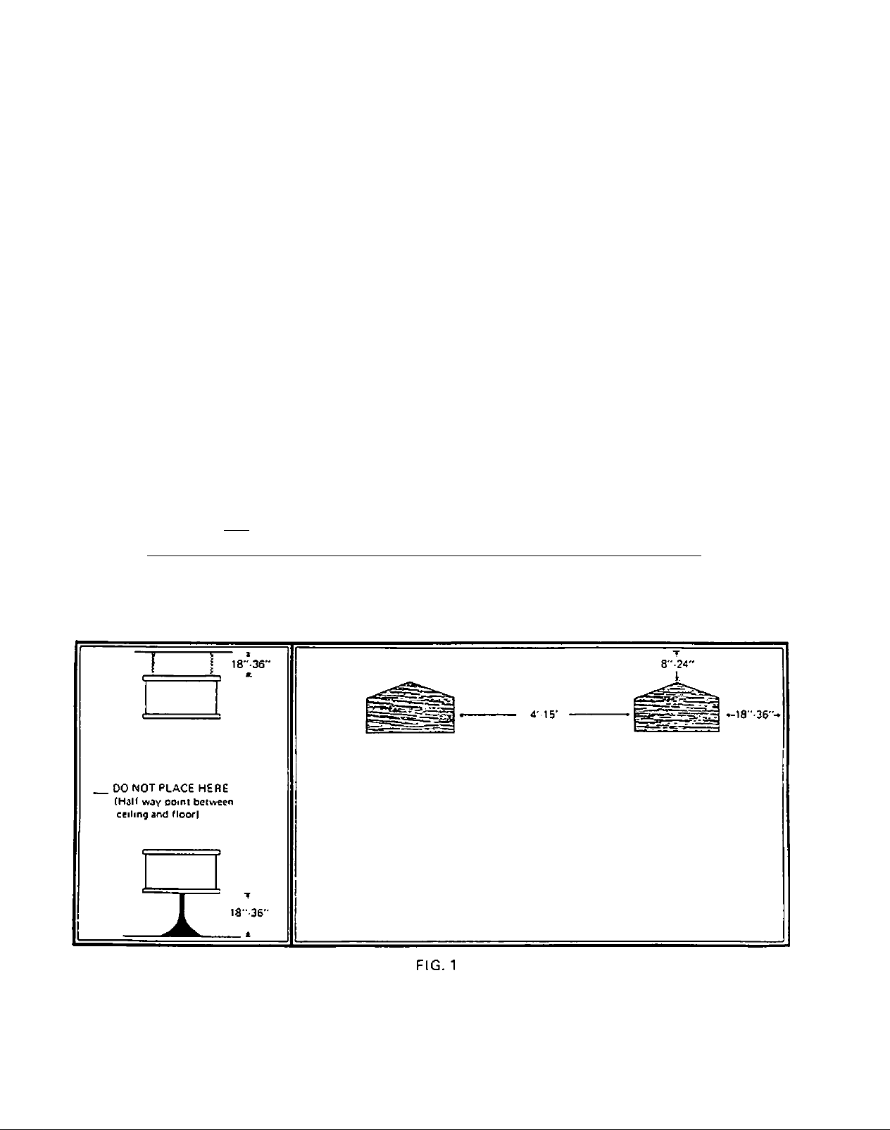
The angled (vee shaped) grille cloth panels are the back of the 901. Point the vee toward the wall. The distance
of the speakers from the wall is very important. The point of the vee should be 12 inches from the wall.
(Although the 901 was designed to be placed 12 inches from a reflecting wall, satisfactory performance can be
obtained anywhere within the range from 8 to 24 inches.) The point of the speaker should be aimed directly at
the reflecting wall, and NOT directly into a corner (See Fig. 11,
The reflecting wall ideally should be made of a dense, solid substance such as wood, brick, cement block, plaster,
or sheetrock. Substances like glass, pegboard. cork, or acoustic tile make ineffective reflecting walls. (The
Equalizer is designed to accommodate surfaces which might otherwise present problems. (See Section IV B.l I
Page 4

The following guidelines should be followed in placing the speakers relative to other surfaces in the room. The
basic idea is to provide space around the speakers to allow sound waves coming from the rear of the speaker to
properly disperse.
1. The speakers should be placed at least 18 inches from the floor.
2. If you are hanging the speakers from the ceiling, they should be positioned no closer than 18 inches from
the celling. DO NOT place your speakers exactly half-way between the floor and the ceiling. (See Fig. 1.)
3. The speakers should be at least 18 inches from the side walls or from openir^gs into adjacent rooms.
4. The speakers should be at least 18 inches from nearby massive objects such as bookcases, cabinets, or other
large pieces of furniture.
5. The separation between the speakers should be between 4 and 15 feet. (Best results will be obtained with a
separation of 6 to 12 feet.)
6. In general, you should use common sense and be sure to select an arrangement which does not appear to
block the radiation and reflection of the sound into the room. The 901s can be placed on pedestals or
tables, on top of cabinets, or on shelves, as tong as the preceding guidelines are followed.
7. If the speakers are in a room with a color television, DO NOT place the speakers closer than 3 feet to the
television. All loudspeakers are equipped with powerful magnets which may disturb the delicate adjust
ments of your color TV.
B. CONNECTING THE SPEAKERS
1. SELECTING THE SPEAKER WIRE
0^
If the wire chosen for connecting the speakers to your amplifier has too much resistance, audible colora
tion of the sound and loss of power can result. The table below summarizes the permissible wire
lengths for 18. 16. and 14 gauge two-conductor copper wire for one or two pairs of BOSE 901 speaker
system(s). Copper zipcord wire is readily available at most electrical and hardware stores. This wire usually
has a ribbed line running along one of the two conductors so that the conductor can be identified at each
end for obtainirtg the proper phasing of your BOSE 901 speakers.
TABLE 1 - WIRE LENGTHS FOR EACH SPEAKER
Type of Speaker
Hook-up Wire
18 gauge zipcord
(or two-conductor wire)
16 gauge two-conducior
wire
14 gauge two-conductor
wire
One Pair
of 901s
33 feet
54 feet
86 feet
Two Pairs
of 901s
14 feet
23 feet
36 feet
0
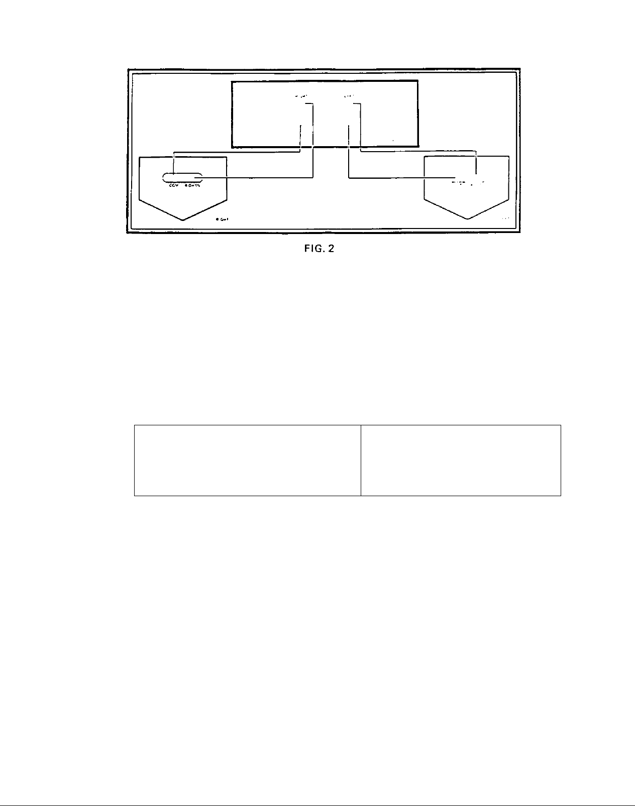
2. PHASING YOUR 901 SPEAKER
It is imporiani that the connections to the speakers and the receiver or amplifier be the same for both
channels so that the two speakers are m phase with each other. The two terminals on the bottom of the 901
are marked ”8 OHMS” and ''COM.'*
♦
Page 5
i
Start with the Part 1 portion of your 901 system. Place it on the left side of your room. Connect
this left speaker to the left channel speaker output terminals of your amplifier or receiver. (If there is a
choice of impedances on the amplifier output, use the terminal marked "8^2" or "8 OHMS''.) *
Connect the "COM" terminal on the left speaker to the "COM" terminal on the left channel output of your
receiver or amplifier output. Connect the "8 OHMS" terminal on the left speaker to the "8 OHMS” ter
minal on the left channel amplifier output. Connect the right speaker (Part 2) in the same manner to the
right channel amplifier outputs {See Fig. 2).
Because of the differing terminology which various manufacturers use on their receivers and amplifiers, we
have provided the chart below to assist you in identifyirtg the proper connection points.
STANDARD RECEIVER/AMPLIFIER TERMINAL MARKINGS
"COMMON" Terminal
also known as "0"
If stranded wire is used, be sure that the loose strands do not touch or short-out the speaker or amplifier
terminals. Also make certain that all amplifier and speaker terminals are tightened securely.
* If two pairs of 901s are being connected in parallel, the terminal marked ”4i2" or ”4 ohms" on the
receiver or amplifier should be used. (See Section IV E.)
3. FUSING YOUR 901 SPEAKERS
Any loudspeaker is subject to damage if the amplifier powering it should fail. The use of a fast-acting fuse
in series with each speaker will minimize the possibility of serious damage to your speakers. BOSE Corpo
ration recommends the use of a 3-ampere fuse, such as a BUSS AGC 3 or a LITTELFUSE 3 AG
(3 amp). The fuse should be connected in series with either of the two wires in the cable to each
speaker. A fuse holder, like a BUSS 3833-1 or a LITTELFUSE 356001. may be used for convenience. (For
two pairs of BOSE 901s, use two 6-ampere fuses.)
C. CONNECTING THE EQUALIZER
"COM"
"Ground" or
"Negative" (-1
"8 OHMS" Terminal
also known as
"8^"
"Hot" or
"Positive" (*)
THIS PART OF THE INSTALLATION DIFFERS FROM THAT OF CONVENTIONAL SPEAKER SYSTEMS.
BE CERTAIN TO FOLLOW THE INSTRUCTIONS GIVEN BELOW, STEP BY STEP.
1. PREFERRED METHOD
(Using The Tape Monitor Circuit)
To provide the proper balance at all frequencies, the 901 Active Equalizer must be connected in your sound
Page 6

system before the final stage of amplification. The connection method described in this section can be used
with virtually all integrated amplifiers, preamplifiers, and receivers. This method usually results in the best
Signal to noise ratio. For the sake of simplicity, we will call these various components the “control amplifier."
The 901 Equalizer is normally connected to your control amplifier as if it were a tape recorder.
utilizes the TAPE MONITOR function and connections of your control amplifier.
FIG. 3
Referring to Figure 3. connect the Equalizer according to the instructions in Steps a through n;
It
r
a. Turn off all power to your equipment.
If you have a tape recorder, disconnect It from the rear panel of your control amplifier. Instructions
in the next section will show you how to reconnect your tape recorder to the system after the
Equalizer has been installed.
THE FOLLOWING STEPS WILL CONNECT THE EQUALIZER TO YOUR PREAMPLIFIER.
RECEIVER, OR INTEGRATED AMPLIFIER. READ THEM CAREFULLY.
Using one of the cables supplied with the Equalizer, connect the RIGHT channel OUTPUT terminal
c.
of the Equalizer to the RIGHT or "B" channel TAPE MONITOR terminal of your control amplifier.
(This terminal may also be labeled TAPE PLAYBACK or TAPE IN.} If your control amplifier has
two tape monitor circuits, see Page 9.
Connect the LEFT channel OUTPUT terminal of the Equalizer to the LEFT or “A" channel tape
monitor terminal of your control amplifier.
Connect the RIGHT channel INPUT terminal of the Equalizer to the RIGHT or "B" channel TAPE
RECORD terminal of your control amplifier. (This terminal may also be labeled TAPE OUT or
REC OUT.l
Connect the LEFT channel INPUT terminal to the LEFT or "A" channel TAPE RECORD terminal of
your control amplifier.
Connect the AC power cord of the Equalizer to a switched outlet of your control equipment so that
the Equalizer will automatically be switched on or off by the power switch of your integrated ampli
fier. receiver, or preamplifier.
If the preceding steps are unclear, it may be due to the different nomenclature which various manu
facturers employ. Consult your integrated amplifier, receiver, or preamplifier instructions and refer
to the section describing steps for connecting a tape recorder to the tape monitor circuit. Remember
that the Equalizer connects like a recorder.
4
Page 7

THE NEXT SEVEN STEPS ARE TESTS WHICH MUST BE PERFORMED TO INSURE PROPER
OPERATION AND CORRECT INSTALLATION.
h.
Place the TAPE switch on the Equalizer in the MONITOR position. Place the 3 frequency contour
controls so that they coincide with the indicated dots. These are the "NORMAL” positions of the
Equalizer controls.
Place the TAPE MONITOR or TAPE FUNCTION switch on your control amplifier in the NORMAL
or OUT position.
Turn the entire system on. 8e sure that the Equalizer is plugged into an operating AC outlet by
!•
observing that the pilot light on the Equalizer is on.
k.
Play your system as you normally would, using a phonograph or AM-FM source (NOT a tape recorder)
to be sure it is operating properly.
This tests the rest of your system, since the Equalizer has not yet been switched into the system.
Any errors must be corrected before proceeding further.
Turn the BALANCE control of the control amplifier to the extreme right and left to check for
correct placement of the right and (eft channels.
m.
With the system playing, move the TAPE MONITOR or TAPE FUNCTION switch on your integrated
amplifier, receiver, or preamplifier to the MON ITOR or "ON" position. The sound should stop. This
TAPE MONITOR switch on your integrated amplifier, preamplifier or receiver should be left in this
position. If the sound does not stop, recheck Steps a through I.
n.
Place the Equalizer TAPE switch in the NORMAL position. The sound should return. If the sound
does not return, and the Equalizer pilot light is on, then the Equalizer is probably connected in
correctly. Recheck Steps a through I.
NOTE: If the TAPE MONITOR switch of your control amplifier is later switched out. the system
will continue to play but the Equalizer will no longer be functioning in the circuit. Since the system
will be playing and the Equalizer pilot light will be on. it will be possible, especially at low-volume
levels or with certain musical selections, for you to be unaware that the Equalizer has been removed
from the circuit. Check the TAPE MONITOR switch on your control equipment periodically to
make certain it is still in the ON position.
If you do not have a tape recorder, the installation of the 901 system is now complete, and the system
is operating properly. If you do have a tape recorder, its connection to the system will be explained
in Section III D.
Page 8

2. ALTERNATE METHOD I
(Using PRE-AMP OUT and MAIN IN Connections with Receivers or Integrated Amplifiers (Refer to Fig. 4.)
mo if««
•VM* t«
’I m fe
11
FIG. 4
An alternate method of connecting the BOSE Active Equalizer makes use of the PRE-AMP OUT and MAIN
IN jacks provided by many manufacturers on their receivers or integrated amplifiers. To do this refer to
your receiver and integrated amplifier owner's instruction manual for separating the main and preamplifier
sections of their units. (This is usually accomplished by removing shorting wires or plugs and/or moving a
slide switch). Connect the PRE-AMP OUT terminals to the Equalizer INPUT terminals, and connect the
EQUALIZER OUTPUT terminals to the MAIN IN terminals of the receiver or integrated amplifier. With
this method of connection, leave the TAPE switch on the Equalizer in the NORMAL position. Tape re
corders are connected to the receiver or amplifier in the conventional manner. The disadvantage of this
method of connection is that it is difficult to use conventional speakers or headphones, because the Equal
izer is always in the circuit.
11
3.
ALTERNATE METHOD M
(Using separate PREAMPLIFIERS and POWER AMPLIFIERS)
The Equalizer can be connected in systems that include separate preamplifiers and power amplifiers,
between the preamplifier and power amplifier (See Fig. 5). The advantage of this method of connection is
that the tape monitor functions of the preamplifier are still available for connection to a tape recorder in
the conventional manner. One disadvantage of this method of connection is that it is difficult to use an
additional pair of conventional loudspeakers or headphones because the Equalizer is permanently in the
circuit. It IS advisable with most power amplifiers having gam controls that these controls be turned
fully clockwise (consult your amplifier manufacturer's owner's manual for recommendations).
Page 9

4. ALTERNATE METHOD HI
iUsing FOUR-CHANNEL DECODERS»
As previously stated, the BOSE Active Equalizer should be connected before the final stage of amplifica
tion of the amplifier channels powering the 901 speakers. Additionally, the Equalizer should be connected
at a point in the signal path following the four-channel decoder to prevent any possible overloading of the
decoding equipment. Because of the many different decoders available, we suggest carefully reading the
owner's instruction manuals of all of the associated equipment regarding system connection. How you
connect the decoder will depend upon your own needs for control of the Equalizer and/or your associated
equipment.
D. CONNECTING A TAPE RECORDER
FIG.6
Since the Active Equalizer has been connected to what are normally the tape recorder terminals of your integrated
amplifier, preamplifier, or receiver, extra terminals are provided on the Equalizer for the connection of a tape
recorder. Follow the next five steps carefully: (Refer to Fig. 6.1
a. Turn all power off.
b. Connect the RIGHT channel TAPE IN terminal on the Equalizer to the RIGHT or "B" channel
OUTPUT terminal on the tape recorder.
c. Similarly, connect the LEFT channel TAPE IN terminal on the Equalizer to the LEFT or "A" channel
OUTPUT terminal of the tape recorder.
d. Connect the RIGHT channel TAPE OUT terminal on the Equalizer to the RIGHT or "B" channel
INPUT (or LINE IN] terminal of the recorder.
e. Similarly, connect the LEFT channel TAPE OUT terminal on the Equalizer to the LEFT or "A"
channel INPUT (or LINE IN) terminal on the recorder.
Installation of the tape recorder is now complete. To play the tape recorder, simply place the TAPE
switch on the 901 Active Equalizer in the MONITOR position (down).
CONTROL AMPLIFIERS HAVING TWO TAPE MONITOR CIRCUITS
Many modern preamplifiers, integrated amplifiers, and receivers have two tape monitor functions
providing the same monitoring features for two tape recorders instead of one. However, most of
these controls are constructed to prevent both monitoring switches from being turned on or
"activated" at the same time. Since the BOSE Active Equalizer must be in the circuit while the 901
speakers are being used, connecting the Equalizer in either TAPE 1 or TAPE 2 will require connecting
your tape recorder to the BOSE Equalizer tape monitor circuit, rw the unused TAPE monitor
position found on your control amplifier.
Page 10

E. CONNECTING HEADPHONES OR CONVENTIONAL SPEAKERS
It is important to remember that the BOSE 901 Active Equalizer introduces substantial boost in the range
below 100 Hz and above 3000 Hz to match the power response of the 901 speakers. This means that if
other speakers or headphones are played while the Equalizer is in the circuit, they will radiate far too much
energy in the low bass and high treble ranges.
MORE IMPORTANTLY. HEADPHONES OR CONVENTIONAL SPEAKERS MAY BE DAMAGED BY
PLAYING WITH THE BOSE 901 EQUALIZER CONNECTED IN THE CIRCUIT.
For these reasons, you should switch the Equalizer out of the circuit by placing the TAPE MONITOR
switch of your preamplifier, integrated amplifier, or receiver to the OFF (or NORMAL) position when play
ing your system through headphones or a pair of speakers other than BOSE 901s.
IV. GETTING THE MOST OUT OF YOUR 901 SPEAKERS
A. ADJUSTING SPEAKER PLACEMENT
There are 3 reasons you might wish to adjust the placement of your 901s: to change the frequency response
of the system; to change the dispersion of sound into the room; or to change the appearance or usefulness
of the room.
The primary influence of speaker placement on frequency response occurs in the mid-bass region
(80-300 Hz). This frequency range includes the fundamental tones of male voice, the low guitar range,
string bass, cello, trombone, and tympani, Moving the vee (the back of the 901) of the speakers closer to
the wall than 12 inches will boost the response in this mid-bass range. Do not move the back of the speaker
any closer to the wall than 8 inches. Moving the vee of the speakers farther from the wall than 12 inches
will decrease the response in the mid-bass range. Do not move the vee more than 18 inches from the wall.
The frequency response in the mid-bass range can also be modified in the same way by moving the speakers
closer to or farther from the floor, the ceiling, or the side walls. In all cases. DO NOT place the speakers
closer than 18 inches from the floor, ceiling, or side walls.
The dispersion of sound into the room can also be affected by moving the two 901 speaker cabinets. If
the stereo image of the music is too narrow, simply move the two speakers farther apart. It is recommended
that the speakers be placed no farther apart than 15 feet. If the image of the sourtd is too broad,
or if there appears to be "too much space in the middle," the speakers can be moved closer together. It is
recommended that the speakers be moved no closer together than 4 feet.
10
Page 11

Additionally, the dispersion can be adjusted by rotating the speakers. For instance, if you wish more sound
to come from the left side of one of the speakers, rotate the rear of the speaker (the vee) to the
left. This technique can also be used to direct sound away from an obstacle (for example, a piece of
furniturej or an opening into an adjacent room. (See F«g. 7.1
The 901s also can be hung from the ceiling. As well as being an effective and interesting decorating
approach, this is a useful method of installation where speaker placement might be difficult due to
furniture, location of doorways, and/or small children. The hardware is readily available at most stores
carrying decorative lighting accessories. We recommend using a three or four point suspension, with three
or four pieces of decorative chain or other strong material. These are attached to the bottom of the 901
cabinet via decorative hooks or eyelets screwed into the cabinet. Keep in mind that each 901 weighs 33
pounds; therefore, use hardware strong enough to support this weight.
The 901 speaker should be placed no closer than 18 inches from the ceiling. If you prefer to suspend the
speakers far above the listening area in a high ceiling room, the sound can be directed downward by angling
the rear of the speaker down. The sound will then be directed downward after it is reflected off the rear
wall. The speaker can be tilted in this manner by adjusting the length of the rear chain(s).
8. ADJUSTING THE EQUALIZER CONTROLS
FIG. 8
BELOW 40
Another way of altering the performance of the 901 system is to adjust the Equaliaer controls. The first
Equalizer control is labeled BELOW 40. This control causes a uniform reduction in bass response of
approximately 8 d6 below 40 Hz. If distortion occurs when you are playing loud musical material with a
great deal of deep bass content, move this switch from the dotted position to the CONTOUR position.
This will allow you to play the system louder, especially with low-powered amplifiers or receivers. This
control is effective also in reducing ‘'rumble*' from older turntables or recordings.
11
Page 12

The effect of the various control settings upon the frequency response (takir>g the normal or "dotted" posi-
12
HIGH FREQUENCY
The next frequency control of the 901 Equalizer is labeled HIGH FREQ. If the control is moved to the
DECREASE position, the frequency response of the system is decreased in the high treble range above
10 kHz. This control may be used as a scratch filter, or to modify the response of some recordings which
are excessively bright in the high treble range.
TREBLE LEVEL
The next frequency control is a rotary switch labeled TREBLE LEVEL. This control has 5 positions.
The third position is the normal, or "dotted" position. The "dotted" position is the preferred position for
use in rooms of average acoustical properties.
In a room that is extremely "bright" due either to room conditions or to the recording you are playing, you
Page 13

may wish to move this control to Position 2 or Position 1. These positions successively decrease the fre
quency response over the entire treble range (above 2000 Hz).
In a room which is extremely "dull/' you may wish to move the TREBLE LEVEL control to Position 4 or
Position 5. This increases the frequency response throughout the entire treble range.
Another benefit of this TREBLE LEVEL control is that it allows the use of the 901 system in front of
reflecting walls which are covered with curtains or drapes. If your reflecting wall is covered with a sound
absorbent material setting the TREBLE LEVEL control to Position 4 or 5 will result in the same frequency
response as if the wall had no draperies covering it. In the final analysis, you should set the TREBLE
LEVEL control to that position which best fits your listening taste, rather than following any rigid
guidelines.
C. IMPROVING ROOM ACOUSTICS
The acoustical properties of a listening room have a very large effect on the quality of sourvj produced in
that room by a sound system. An overly "live" room has hard walls and little in the way of soft soursd
absorbing material like rugs, sofas, and drapes. Not only is music listening likely to be unpleasant in such a
room, but it may even be uncomfortable to carry on a normal conversation. The properties of such a room
can be greatly improved by adding some sound absorbing material. This can be done by adding a rug.
cushioned furniture, curtains or drapes, or wall hangings.
Rooms which have too much absorbing material tend to be acoustically "dead." In such rooms, music will
seem lifeless, and conversation may sound as if you were outdoors. A "dead" room can be improved by re
moving some sound absorbing material such as curtains, drapes, or cushioned furniture.
D. SELECTING THE RIGHT amplifier
Most modern amplifiers or receivers will provide satisfactory performance for most owners of the BOSE
901 system. We recommend that you select an amplifier or receiver which is capable of delivering 25 watts
rms per channel or more into 8 ohms. If your listening room is rather large or "dead" or if your listening
tastes call for fairly high volume levels, you may want to consider purchasing an amplifier or receiver which
can deliver 50-70 watts rms per channel into 8 ohms. An amplifier of this size is sufficient to satisfy the
vast majority of listeners.
Some listeners prefer very high volume levels. If such levels are to your likir>g. you will be most pleased
with the 901 system. The BOSE 901 can handle much more power than conventional loudspeaker systems.
Listeners who demand extremely high volume levels should consider amplifiers in the power range of 100
to 270 watts rms per channel into 8 ohms. To reproduce the highest sound levels in the home, you may
select an amplifier capable of delivering up to 270 watts rms per channel into 8 ohms without exceeding
the safe operating limits of the 901.
E. THE ONLY SYSTEM BETTER THAN A PAIR OF 901s
The 901 was designed to outperform all other high fidelity speakers, regardless of their size or price. If we
were to make a speaker twice as big or twice as expensive as the 901. we could not significantly improve its
performance. However, using two pairs of 901s substantially adds to the quality of the performance. The
advantages of a second pair include; expanding the spatial properties of the performance; increasing the
efficiency of bass reproduction; and increasing the power available from most amplifiers.
The ideal placement is "around the corners" from the first pair (See Fig. 11). The same distances apply,
from the reflecting wall, floor, ceiling, and side wall, as for the first pair of speakers. The effect of this
arrangement is to bring the "stage" out around the listener in an acoustic panorama.
13
Page 14

Since the second pair of speakers is connected in parallel with the first pair, a second Equalizer is not
required. For this reason, the BOSE 901 is available at lower cost as an "Add-On Pair," without the Equal
izer. To connect the second pair of speakers, simply connect the 8 OHMS terminal of the second left
speaker to the 8 OHMS terminal of the first left speaker. Connect the COM terminal of the second left
speaker to the COM terminal of the first left speaker. Follow a similar procedure for the right speaker.
Note: If your amplifier has separate output connections for different speaker impedances, you should
connect each pair of speakers to the 4 OHM terminals of your power amplifier.
V. IN CASE OF DIFFICULTY
If you suspect that there is a problem with your 901 system, it is worth a few minutes of your time to determine
whether your 901s are defective; and if so. that you return only that part of the system which is defective.
If one speaker sounds defective, switch the left and right channel speaker cables at the point where they are connected
to the amplifier or receiver. If the trouble moves to the other speaker, it is not in the speakers or in the speaker wiring.
As noted earlier in this manual, if you hear distortion with both speakers at high sound levels which disappears when
you turn the volume down or switch the BELOW 40 switch to CONTOUR, you are probably overloading the ampli
fier. If this is the case, leave the BELOW 40 switch in the CONTOUR position for the recording you are playing.
(See Section IV, 0.1
If the trouble seems to be in the Equalizer, be sure that the system operates properly with the Equalizer out of the
circuit. Check this by switching the preamplifier or receiver TAPE MONITOR switch to the OUT or NORMAL
position. Be certain that all cables are connected properly and that the cables are not defective.
If the trouble persists, contact your dealer. He will arrange for service either by having the unit serviced at a FactoryAuthorized Service Agency or at the BOSE Factory. If it becomes necessary to return your unit to the Factory, he can
obtain a Return Authorization Number which must appear on the outside of the carton when the unit is returned to
the Factory. Shipments arriving at the BOSE Factory without a RETURN AUTHORIZATION NUMBER on the outside
of the carton are not accepted, but are returned freight collect to the sender. Units must be returned prepaid. 00 NOT
SHIP VIA PARCEL POST.
FIG. n
VI. TECHNICAL INFORMATION
A. The System is packed in Two Cartons Marked "Part I" and "Part 2"
Weight; Part 1 — 44 pounds
Part 2-42 pounds
Carton Dimensions; 22-3/4" W x 15" H x 16-1/2" 0
14
Page 15

B. The Speaker
Dimensions: 20-9/16" W x 12-3/4" H x 12-7/8" D
Weight: 33 pounds
Nominal Impedance: 8 ohms
C. Percentages of Direct and Reflected Sound Radiation
Power radiated by reflection: 89%
Power radiated directly: 11%
(Design percentages based on concert hall acoustics)
D. Power Handling
Continuous sine wave power at any frequency: 50 watts
Minimum recommended amplifier power: 25 watts rms per channel into 8 ohms
Peak power handling ability (less than five secor>ds}: 400 watts
Maximum recommended amplifier power for speech and music: 270 watts rms into 8 ohms
E. Damping Factor
Any amplifier with a damping factor of 40 or higher meets the requirements of the 901. (The wire size recommenda
tions of Table 1 on Page 4 must be followed.)
F. Driver Complement
Each unit contains 9 high-compliance full-range drivers with high energy magnets to allow large excursions without
audible distortion on any program material. The drivers are acoustically coupled to eliminate audible resonances.
VI
Nominal driver diameter: 4-1/2"
Maximum driver excursion: +1/4"
Nominal driver impedance: 8 ohms
Weight of each ceramic magnet: 9.6 ounces
G. The Active Equalizer
Dimensions: 2-13/16" H x 9-1/4" W x 6-3/4” 0
Input Impedance: 150k ohms
Output Impedance: less than 100 ohms
Minimum Load Impedance: 5k ohms
Maximum Output Voltage: 4.0 volts
Maximum Gain: 18 d6 at 35 Hz.
ACCESSORIES AND OPTIONS
WALNUT FACINGS
The BOSE 901 is available with walnut facings, to provide the rich look of walnut grain arour>d the entire cabinet.
The small grille panel on each speaker front allows a choice of fabrics. Walnut facings are available as a separate
add-on kit and are not intended for use with the 901 Continental.
PEDESTALS
Specially designed pedestals are available for the 901. They are 18 inches high, and available in either white,
black or chrome.
15
Page 16

VIII. FIVE YEAR WARRANTY
We warrant the BOSE 901 speaker system to be free from defects in material and workmanship. BOSE will replace any
defective part and correct any defect in workmanship or performance, without charge for either parts or labor. The
obligation of BOSE under the terms of this warranty is effective only if the defect develops in a normal installation,
under normal use and service, within a period of FIVE years from the date of purchase, subject to the following terms
and conditions:
1. You purchased your BOSE system new from an authorized BOSE dealer. Proof of purchase by original sales slip
or otherwise is required to expedite repairs under warranty.
2. The speaker is used in accordance with instructions in Owner's Manual.
3. Such defect was not caused by abuse, neglect or accident, and no unauthorized repairs have been made.
4. Our responsibility is limited to the repair and replacement of units properly packed and returned PREPAID to
the BOSE Factory or BOSE Factory-Authorized Service Agencies. Return freight charges will be paid by BOSE.
Shipping cartons can be obtained from BOSE Dealers or the BOSE Factory. ANY DAMAGE IN TRANSIT due to
improper packing is not covered by the warranty and will not be recognized as an insurance claim by our trans
portation companies. DO NOT SHIP BOSE SPEAKERS PARCEL POST.
5. We assume no liability for installation labor or consequential damages.
6. All service must be provided by BOSE Factory or Factory-Authorized Service Agency. Failure to comply invali
dates your warranty.
7. The serial number must not be defaced, removed, or otherwise obliterated, and must correspond to the number
on the completed Warranty Card on file with BOSE.
SHOULD YOUR UNIT APPEAR TO BE DEFECTIVE. DO NOT RETURN THE UNIT TO THE FACTORY. TAKE
THE UNIT TO YOUR DEALER. HE WILL ARRANGE FOR REPAIRS.
IF IT BECOMES NECESSARY TO RETURN YOUR UNIT TO THE FACTORY. DO NOT RETURN YOUR SPEAK
ERS WITHOUT FIRST RECEIVING A RETURN AUTHORIZATION NUMBER.
BOSE CORPORATION • THE MOUNTAIN • FRAMINGHAM, MASS. 01701
»034 76-77;
 Loading...