

Page 1
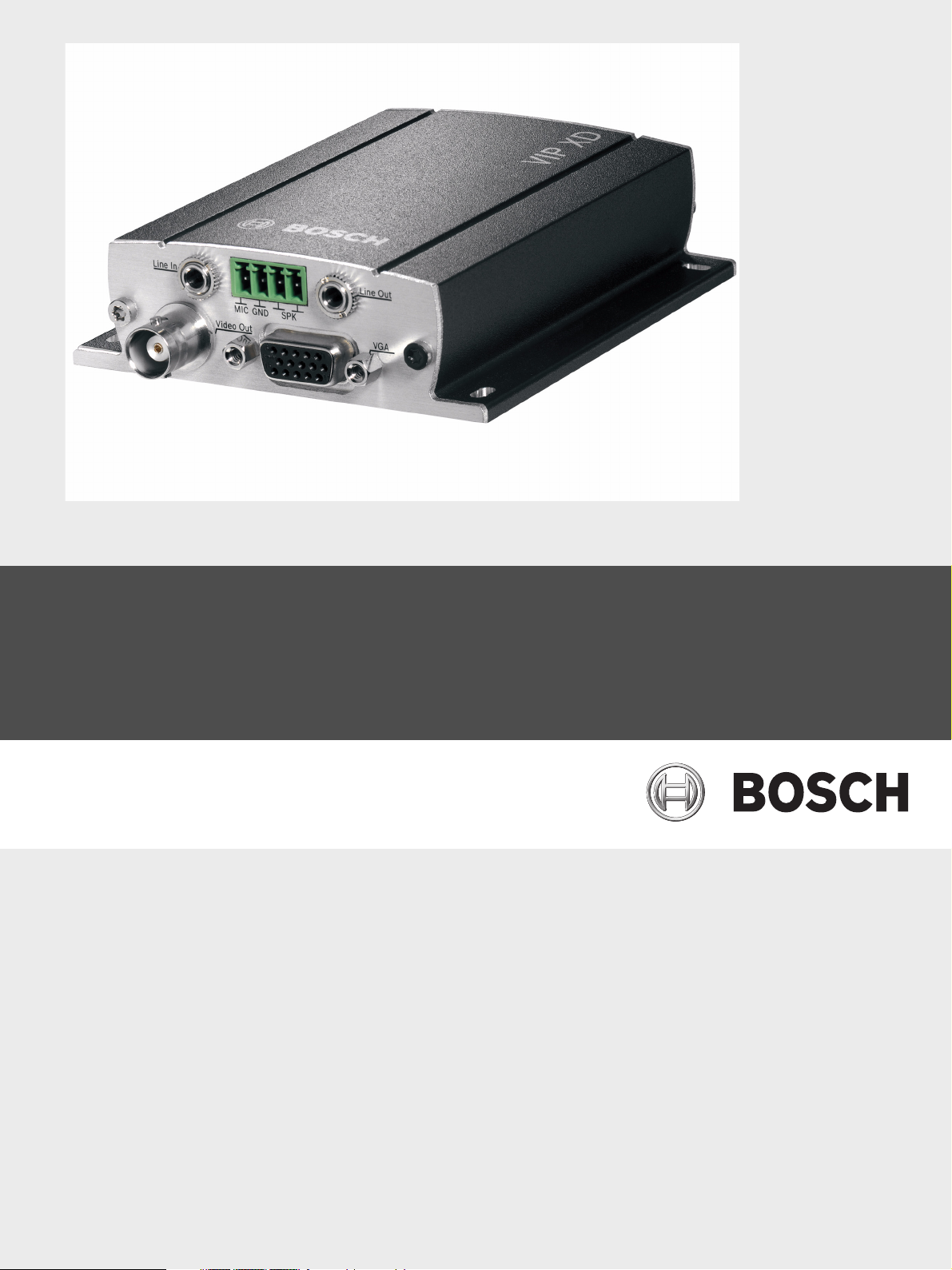
VIP XD
Network Video Server
en Installation and Operating Manual
Page 2

VIP XD
Page 3

VIP XD Table of Contents | en 3
Table of Contents
1Preface 5
1.1 About this Manual 5
1.2 Conventions in this Manual 5
1.3 Intended Use 5
1.4 EU Directives 6
1.5 Rating Plate 6
2 Safety Information 7
2.1 Electric Shock Hazard 7
2.2 Installation and Operation 7
2.3 Maintenance and Repair 7
3 Product Description 9
3.1 Scope of Delivery 9
3.2 System Requirements 10
3.3 Overview of Functions 11
3.4 Connections on the Front Panel 13
3.5 Connections on the Rear Panel 14
4 Installation 15
4.1 Preparations 15
4.2 Connections 16
4.3 Power On/Power Off 19
4.4 Setup Using the Configuration Manager 19
5 Configuration Using a Web Browser 21
5.1 Connecting 21
5.2 Configuration Menu 24
5.3 Identification 25
5.4 Password 25
5.5 Date/Time 26
5.6 Appearance 28
5.7 Decoder Profile 29
5.8 VGA 30
5.9 Monitor Display 33
5.10 Audio (Audio Version Only) 33
5.11 Alarm Connections 34
5.12 Audio Alarm (Audio Version Only) 37
5.13 Alarm E-Mail 38
5.14 Alarm Task Editor 40
5.15 Alarm Inputs 41
5.16 Relay 41
5.17 COM1 43
5.18 Network 44
5.19 Advanced 47
Bosch Security Systems Installation and Operating Manual DOC | V4.0 | 2009.06
Page 4

4 en | Table of Contents VIP XD
5.20 Encryption 48
5.21 Maintenance 49
5.22 Licenses 51
5.23 System Overview 51
5.24 Function Test 52
6Operation 53
6.1 Connecting 53
6.2 The CONNECTIONS Page 56
6.3 Connections Between the Sender and Receiver 57
6.4 Hardware Connections Between Video Servers 59
6.5 Operation with Management Software 60
7 Maintenance and Upgrades 61
7.1 Testing the Network Connection 61
7.2 Unit Reset 61
7.3 Repairs 62
7.4 Transfer and Disposal 62
8 Appendix 63
8.1 Troubleshooting 63
8.2 LEDs 65
8.3 Processor Load 65
8.4 Network Connection 65
8.5 Serial Interface 66
8.6 Terminal Block 66
8.7 Communication with Terminal Program 67
8.8 Copyrights 69
9 Specifications 71
9.1 Unit 71
9.2 Protocols/Standards 72
10 Glossary 73
11 Index 77
DOC | V4.0 | 2009.06 Installation and Operating Manual Bosch Security Systems
Page 5
VIP XD Preface | en 5
!
i
1Preface
1.1 About this Manual
This manual is intended for persons responsible for the installation and operation of the
VIP XD. International, national and any regional electrical engineering regulations must be
followed at all times. Relevant knowledge of network technology is required. The manual
describes the installation and operation of the unit.
1.2 Conventions in this Manual
In this manual, the following symbols and notations are used to draw attention to special
situations:
CAUTION!
This symbol indicates that failure to follow the safety instructions described may endanger
persons and cause damage to the unit or other equipment.
It is associated with immediate, direct hazards.
NOTICE!
This symbol refers to features and indicates tips and information for easier, more convenient
use of the unit.
1.3 Intended Use
The VIP XD network video server receives video and control signals over data networks
(Ethernet LAN, Internet). Audio signals can also be transmitted with the audio version of the
unit. The units are designed for use in CCTV systems. Various functions can be triggered
automatically by incorporating external alarm sensors. Other applications are not permitted.
In the event of questions concerning the use of the unit which are not answered in this
manual, please contact your sales partner or:
Bosch Security Systems
Robert-Koch-Straße 100
85521 Ottobrunn
Germany
www.boschsecurity.com
Bosch Security Systems Installation and Operating Manual DOC | V4.0 | 2009.06
Page 6

6 en | Preface VIP XD
1.4 EU Directives
The VIP XD network video server complies with the requirements of EU Directives 89/336
(Electromagnetic Compatibility) and 73/23, amended by 93/68 (Low Voltage Directive).
1.5 Rating Plate
For exact identification, the model name and serial number are inscribed on the bottom of the
housing. Please make a note of this information before installation, if necessary, so as to have
it to hand in case of questions or when ordering spare parts.
DOC | V4.0 | 2009.06 Installation and Operating Manual Bosch Security Systems
Page 7

XIP XD Safety Information | en 7
2 Safety Information
2.1 Electric Shock Hazard
– Never attempt to connect the unit to any power network other than the type for which it
is intended.
– Use only the power supply unit provided.
– Never open the housing.
– Never open the housing of the power supply unit.
– If a fault occurs, disconnect the power supply unit from the power supply and from all
other units.
– Install the power supply and the unit only in a dry, weather-protected location.
– If safe operation of the unit cannot be ensured, remove it from service and secure it to
prevent unauthorized operation. In such cases, have the unit checked by Bosch Security
Systems.
Safe operation is no longer possible in the following cases:
– if there is visible damage to the unit or power cables,
– if the unit no longer operates correctly,
– if the unit has been exposed to rain or moisture,
– if foreign bodies have penetrated the unit,
– after long storage under adverse conditions, or
– after exposure to extreme stress in transit.
2.2 Installation and Operation
– The relevant electrical engineering regulations and guidelines must be complied with at
all times during installation.
– Relevant knowledge of network technology is required to install the unit.
– Before installing or operating the unit, make sure you have read and understood the
documentation for the other equipment connected to it, such as monitors. The
documentation contains important safety instructions and information about permitted
uses.
– Perform only the installation and operation steps described in this manual. Any other
actions may lead to personal injury, damage to property or damage to the equipment.
2.3 Maintenance and Repair
– Never open the housing of the VIP XD. The unit does not contain any user-serviceable
parts.
– Never open the housing of the power supply unit. The power supply unit does not contain
any user-serviceable parts.
– Ensure that all maintenance or repair work is carried out only by qualified personnel
(electrical engineers or network technology specialists).
Bosch Security Systems Installation and Operating Manual DOC | V4.0 | 2009.06
Page 8

8 en | Safety Information XIP XD
DOC | V4.0 | 2009.06 Installation and Operating Manual Bosch Security Systems
Page 9
VIP XD Product Description | en 9
i
3 Product Description
3.1 Scope of Delivery
– VIP XD network video server (basic version or audio version)
– Power supply unit with four primary adapters
– Configuration cable
– Quick Installation Guide
– Product CD with the following content:
– Quick Installation Guide
–Manual
– System Requirements document
– Further documentation on Bosch Security Systems products
– Configuration Manager
–MPEG ActiveX control
– Player and Archive Player
– DirectX control
– Microsoft Internet Explorer
– Sun JVM
– Adobe Acrobat Reader
NOTICE!
Check that the delivery is complete and in perfect condition. Arrange for the unit to be
checked by Bosch Security Systems if you find any damage.
Bosch Security Systems Installation and Operating Manual DOC | V4.0 | 2009.06
Page 10
10 en | Product Description VIP XD
i
3.2 System Requirements
General Requirements
– Computer with Windows XP or Windows Vista operating system
– Network access (Intranet or Internet)
– Screen resolution 1,024 × 768 pixels
– 16- or 32-bit color depth
– Installed Sun JVM
NOTICE!
Also note the information in the System Requirements document on the product CD
supplied. If necessary, you can install the required programs and controls from the product
CD supplied (see Section 3.1 Scope of Delivery, page 9).
The Web browser must be configured to enable Cookies to be set from the IP address of the
unit.
In Windows Vista, deactivate protected mode on the Security tab under Internet Options.
You can find notes on using Microsoft Internet Explorer in the online Help in Internet Explorer.
Additional Configuration Requirements
– Microsoft Internet Explorer (version 6.0 or higher)
or
– Installed Configuration Manager program (version 2.0 or higher)
Additional Operational Requirements
– Microsoft Internet Explorer (version 6.0 or higher)
or
– Management software, for example VIDOS (version 3.11 or higher) or Bosch Video
Management System (version 2.02 or higher)
DOC | V4.0 | 2009.06 Installation and Operating Manual Bosch Security Systems
Page 11

VIP XD Product Description | en 11
3.3 Overview of Functions
Network Video Receiver with Quad View
The VIP XD is an ultra-compact network video receiver for simultaneous reception of up to
four video streams. It is primarily designed for decoding video data after transfer over an IP
network and for transmitting control data. When connected to a monitor and used in
conjunction with compatible MPEG-4 video servers, the VIP XD is ideally suited for making
existing analog CCTV systems IP-compatible.
The VIP XD is small enough to be easily integrated into small housings as well. The use of
existing networks means that integration with CCTV systems or local networks can be
achieved quickly and easily.
Two units, for example a VIP X1600 as a sender and a VIP XD as a receiver, can create a
standalone system for data transfer without a PC. Video images from a single sender can be
received simultaneously on multiple receivers. A VIP XD receiver can simultaneously receive
up to four video streams from one or more compatible senders.
The audio version of the VIP XD also allows the transmission of audio signals from and to
compatible units.
Sender
Compatible hardware encoders can be used as senders, for example VIP X1, VIP X1600 or
VideoJet X40. Computers with installed VIDOS software are suitable for convenient
connection of the required senders to the respective receivers.
Multicast
In suitably configured networks, the multicast function enables simultaneous real-time video
transmission to multiple receivers. The UDP and IGMP V2 protocols must be implemented on
the network for this function.
Encryption
The VIP XD offers a variety of options for protection against unauthorized reading. Web
browser connections can be protected using HTTPS. You can protect the control channels via
the SSL encryption protocol. With an additional license, the user data itself can be encrypted.
Configuration
The VIP XD can be configured with a Web browser on the local network (Intranet) or via the
Internet. Alternatively, you can perform the configuration using the Configuration Manager
program, which is contained on the product CD included in the scope of delivery.
In the same way, firmware updates and fast loading of device configurations are possible.
Bosch Security Systems Installation and Operating Manual DOC | V4.0 | 2009.06
Page 12

12 en | Product Description VIP XD
Summary
The VIP XD provides the following main functions:
– Video and data reception over IP data networks
– Quad view function with simultaneous decoding of four video streams
– BNC composite video output (PAL/NTSC) for connecting an analog monitor and
Sub-D video interface (VGA/SVGA) for connecting a computer monitor
– Video decoding using MPEG-4, MPEG-2 and H.264
– Integrated Ethernet port (10/100 Base-T)
– Transparent, bidirectional data channel via RS-232/RS-422/RS-485 serial interface
– Configuration and remote control of all internal functions via TCP/IP, also secured via
HTTPS
– Password protection to prevent unauthorized connection or configuration changes
– Four alarm inputs for external sensors (such as door contacts)
– Relay output for switching external units (such as lamps or sirens)
– Event-controlled automatic connection
– Convenient maintenance via uploads
– Flexible encryption of control and data channels
– Authentication according to international standard 802.1x
The audio version also offers:
– Transmission and receipt of audio signals
– Bidirectional audio (mono) for line or microphone/speaker links
– Audio encoding to international standard G.711
DOC | V4.0 | 2009.06 Installation and Operating Manual Bosch Security Systems
Page 13
VIP XD Product Description | en 13
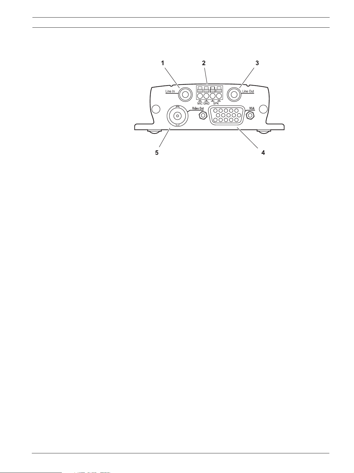
3.4 Connections on the Front Panel
1LineIn audio line input (audio version only)
3.5 mm / 1/8 in. stereo socket for connecting an audio line input signal
2 Terminal connector (audio version only)
for microphone and loudspeaker connections
3LineOut audio line output (audio versions only)
3.5 mm / 1/8 in. stereo socket for connecting an audio line output signal
4VGA video output
Sub-D socket for connecting a computer monitor
5VideoOut video output
BNC socket for connecting a video monitor
Bosch Security Systems Installation and Operating Manual DOC | V4.0 | 2009.06
Page 14
14 en | Product Description VIP XD
i
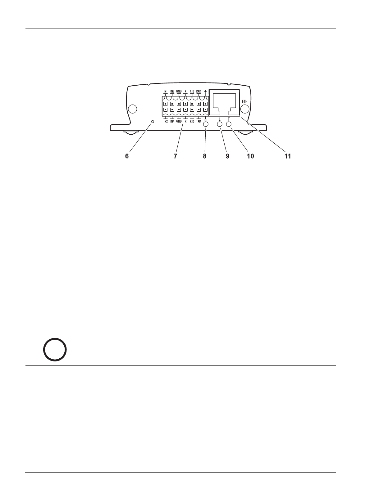
3.5 Connections on the Rear Panel
6 Factory reset button
to restore factory default settings
7 Terminal block
for alarm inputs, relay output, serial interface and power supply
8 Operating status LED
lights up green when ready for operation
9L LED
lights up green when the unit is connected to the network
10 T LED
flashes orange when data is being transmitted over the network
11 ETH RJ45 socket
for connecting to an Ethernet LAN (local network), 10/100 MBit Base-T
NOTICE!
For more information about the LEDs, see Section 8.2 LEDs, page 65.
For terminal block assignment, see Section 8.6 Terminal Block, page 66.
DOC | V4.0 | 2009.06 Installation and Operating Manual Bosch Security Systems
Page 15
VIP XD Installation | en 15
!
4 Installation
4.1 Preparations
Thanks to its ultra-compact dimensions, the VIP XD is particularly well suited to installation in
cabinets or consoles where space is at a premium.
CAUTION!
The unit is intended for use indoors or in housings.
Select a suitable location for installation that guarantees to meet the environmental
conditions. The ambient temperature must be between 0 and +50 °C (+32 and +122 °F). The
relative humidity must not exceed 95%.
The VIP XD generates heat during operation, so you should ensure that there is adequate
ventilation and enough clearance between the unit and heat-sensitive objects or equipment.
Please ensure the following installation conditions:
– Do not install the unit close to heaters or other heat sources. Avoid locations exposed to
direct sunlight.
– Allow sufficient space for running cables.
– Ensure that the unit has adequate ventilation.
– When making connections, use only the cables supplied or use appropriate cables
immune to electromagnetic interference.
– Position and run all cables so that they are protected from damage, and provide
adequate cable strain relief where needed.
– Avoid impacts, blows and severe vibrations as these can irreparably damage the unit.
Bosch Security Systems Installation and Operating Manual DOC | V4.0 | 2009.06
Page 16
16 en | Installation VIP XD
i
4.2 Connections
Monitors
As required, you can connect an analog video monitor (PAL/NTSC) or a VGA-compatible
computer monitor.
X Connect an analog video monitor to the BNC Video Out socket using a video cable
(75 Ohm, BNC plug) or
X connect a VGA-compatible computer monitor to the VGA sub-D socket using a video
cable (VGA,
15-pin sub-D plug).
Audio Connections (Audio Version Only)
The audio version of the VIP XD has two audio ports for audio line signals as well as a
microphone input and a loudspeaker output.
The audio signals are transmitted two-way and in sync with the video signals. As a result, you
can connect a speaker or door intercom system at the destination point, for example.
NOTICE!
If possible you should use the line ports of the intercom for transmitting audio signals on the
intercom systems. The following specifications should be complied with in all cases.
Line In: Impedance 9 kOhm typ., 5.5 V
Line Out: Impedance 16 Ohm min., 3 V
MIC (microphone): Impedance 2 kOhm typ., 2.8 V
–20 dB in, power supply 2.3 V typ.
SPK (loudspeaker): Impedance 4 Ohm min., 6 V
power output RMS 1 W
The stereo plugs must be connected as follows:
Contact Function
Tip Channel 1
Middle ring –
Lower ring Ground
1. Connect an audio source with line level to the Line In socket of the VIP XD with a 3.5 mm
stereo plug.
2. Connect a unit with line-in connection to the Line Out socket of the VIP XD with a 3.5 mm
stereo plug.
If you wish to connect a microphone and a loudspeaker directly:
1. Connect the microphone cords to the MIC and GND connections on the push-in terminal.
2. Connect the loudspeaker cords to the SPK connections on the push-in terminal.
max. input voltage
p-p
max. output voltage
p-p
max. input voltage,
p-p
max. output voltage,
p-p
DOC | V4.0 | 2009.06 Installation and Operating Manual Bosch Security Systems
Page 17
VIP XD Installation | en 17
!
i
i
Network
You can connect the VIP XD to a 10/100 Base-T network using a standard UTP category 5
cable with RJ45 plugs.
X Connect the VIP XD to the network via the ETH socket.
Data Interface
The bi-directional data interface is used to control units connected to the VIP XD, for example
a control panel for dome cameras with motorized lens. The connection supports the RS-232,
RS-422 and RS-485 transmission standards.
The VIP XD offers the serial interface via the orange terminal block (see Section 8.6 Terminal
Block, page 66).
The range of controllable equipment is expanding constantly. The manufacturers of the
relevant equipment provide specific information on installation and control.
CAUTION!
Please take note of the appropriate documentation when installing and operating the unit to
be controlled.
The documentation contains important safety instructions and information about permitted
uses.
NOTICE!
A video connection is necessary to transmit transparent data.
Alarm Inputs
The VIP XD has four alarm inputs on the orange terminal block (see Section 8.6 Terminal Block,
page 66). The alarm inputs are used to connect to external alarm devices such as door
contacts or sensors. With the appropriate configuration, an alarm sensor can automatically
connect the VIP XD to a particular sender, for example.
A zero potential closing contact or switch can be used as the actuator.
NOTICE!
If possible, use a bounce-free contact system as the actuator.
X Connect the lines to the appropriate terminals on the orange terminal block (IN1 to IN4)
and check that the connection is secure.
Bosch Security Systems Installation and Operating Manual DOC | V4.0 | 2009.06
Page 18

18 en | Installation VIP XD
!
Relay Output
The VIP XD has a relay output for switching external units such as lamps or sirens. This relay
output can be activated manually during a connection session with the VIP XD. The output can
also be configured to automatically activate sirens or other alarm units in response to an
alarm signal. The relay output is also located on the orange terminal block (see
Section 8.6 Terminal Block, page 66).
CAUTION!
The maximum rating of the relay contact is 30 V and 2 A (SELV).
X Connect the lines to the appropriate terminals of the orange terminal block (R) and
check that the connection is secure.
DOC | V4.0 | 2009.06 Installation and Operating Manual Bosch Security Systems
Page 19
VIP XD Installation | en 19
!
i
4.3 Power On/Power Off
Power Supply
The VIP XD comes with a plug-in power supply unit (PSU) with four primary adapters and a
terminal block. The VIP XD does not have a power switch. The VIP XD is ready for operation as
soon as it is connected to the power supply.
CAUTION!
The VIP XD may only be operated using the supplied PSU with the correct primary adapter for
your power outlet.
Where necessary, use suitable equipment to ensure that the power supply is free from
interference such as voltage surges, spikes or voltage drops.
Do not connect the VIP XD to the power supply until all other connections have been made.
1. Plug the terminal block with the PSU cable connected to it into the orange socket on the
VIP XD.
2. Ensure that the correct primary adapter is attached to the power supply unit and that a
suitable power outlet is available.
3. Plug the power supply unit into the grounded power outlet. The unit is ready for
operation as soon as the operating status LED stops flashing red during start-up and
lights up green.
Provided the network connection has been correctly made, the green L LED also lights up.
The flashing orange T LED indicates data traffic on the network.
4.4 Setup Using the Configuration Manager
The Configuration Manager program can be found on the product CD contained in the scope
of delivery. This program allows you to implement and set up new video servers in the
network quickly and conveniently.
NOTICE!
Using the Configuration Manager to set all parameters in the VIP XD is an alternative to
configuration by means of a Web browser, as described in chapter 5 of this manual.
Installing the Program
1. Insert the CD into the computer's CD-ROM drive.
2. If the CD does not start automatically, open the Configuration Manager directory using
Windows Explorer and double-click Setup.exe.
3. Follow the on-screen instructions.
Bosch Security Systems Installation and Operating Manual DOC | V4.0 | 2009.06
Page 20
20 en | Installation VIP XD
i
Configuring the VIP XD
You can start the Configuration Manager immediately after installation.
1. Double-click the icon on the desktop or start the program via the Start menu. After the
program has started, the network is immediately searched for compatible video servers.
2. You can start the configuration if a VIP XD is shown in the list in the left section of the
window. To do this, right-click the entry for the unit.
3. Click Unit network settings... in the popup menu.
4. In the Unit IP address field, enter a valid IP address for your network (for example
192.168.0.32) and click OK. The unit reboots and the IP address is valid.
5. If required, enter an appropriate subnet mask for the IP address, and additional network
data.
NOTICE!
You must reboot to activate the new IP address, a new subnet mask or a gateway IP address.
Reboot
You can trigger the reboot directly with the assistance of the Configuration Manager.
X Right-click the entry for the unit in the list in the left section of the window and select the
Reset command from the context menu.
Additional Parameters
You can check and set additional parameters with the assistance of the Configuration
Manager. You can find detailed information on this in the documentation for this program.
DOC | V4.0 | 2009.06 Installation and Operating Manual Bosch Security Systems
Page 21
VIP XD Configuration Using a Web Browser | en 21
i
5 Configuration Using a Web Browser
5.1 Connecting
The integrated HTTP server in the VIP XD provides you with the option to configure the unit
over the network with a Web browser. This option is an alternative to configuration using the
Configuration Manager program and is considerably richer in function and more convenient
than configuration using the terminal program.
System Requirements
– Computer with Windows XP or Windows Vista operating system
– Network access (Intranet or Internet)
– Microsoft Internet Explorer (version 6.0 or higher)
– Screen resolution 1,024 × 768 pixels
– 16- or 32-bit color depth
– Installed Sun JVM
NOTICE!
Also note the information in the System Requirements document on the product CD
supplied. If necessary, you can install the required programs and controls from the product
CD supplied (see Section 3.1 Scope of Delivery, page 9).
The Web browser must be configured to enable Cookies to be set from the IP address of the
unit.
In Windows Vista, deactivate protected mode on the Security tab under Internet Options.
You can find notes on using Microsoft Internet Explorer in the online Help in Internet Explorer.
Installing MPEG ActiveX
Suitable MPEG ActiveX software must be installed on the computer to allow the live video
images to be played back. If necessary, you can install the program from the product CD
supplied.
1. Insert the product CD into the computer's CD-ROM drive. If the CD does not start
automatically, open the root directory of the CD in Windows Explorer and double-click
MPEGAx.exe.
2. Follow the on-screen instructions.
Bosch Security Systems Installation and Operating Manual DOC | V4.0 | 2009.06
Page 22
22 en | Configuration Using a Web Browser VIP XD
Establishing the Connection
The VIP XD must be assigned a valid IP address to operate on your network.
The following default address is preset at the factory: 192.168.0.1
1. Start the Web browser.
2. Enter the IP address of the VIP XD as the URL. The connection is established and after a
short time you will see the CONNECTIONS page.
Maximum Number of Connections
If you do not connect, the unit may have reached its maximum number of connections.
Depending on the unit and network configuration, each VIP XD can have up to 25 Web
browser connections or up to 50 connections via VIDOS or Bosch Video Management System.
DOC | V4.0 | 2009.06 Installation and Operating Manual Bosch Security Systems
Page 23

VIP XD Configuration Using a Web Browser | en 23
i
Protected VIP XD
If the VIP XD is password protected against unauthorized access, the Web browser displays a
corresponding message and prompts you to enter the password when you attempt to access
protected areas.
NOTICE!
The VIP XD offers the option to limit the extent of access using various authorization levels
(see Section 5.4 Password, page 25).
1. Enter the user name and associated password in the corresponding text fields.
2. Click OK. If the password is entered correctly, the Web browser displays the page that
was called up.
Protected Network
If a RADIUS server is employed in the network for managing access rights (802.1x
authentication), the VIP XD must be configured accordingly, otherwise no communication is
possible.
To configure the unit, you must connect the VIP XD directly to a computer using a network
cable. This is because communication via the network is not enabled until the Identity and
Password parameters have been set and successfully authenticated (see
Section Authentication, page 48).
Bosch Security Systems Installation and Operating Manual DOC | V4.0 | 2009.06
Page 24
24 en | Configuration Using a Web Browser VIP XD
!
!
5.2 Configuration Menu
The SETTINGS page provides access to the configuration menu, which contains all the unit's
parameters arranged in groups.
You can view the current settings by opening one of the configuration screens. You can
change the settings by entering new values or by selecting a predefined value from a list field.
All parameter groups are described in this chapter in the order in which they are listed in the
configuration menu, from the top of the screen to the bottom.
CAUTION!
The settings in the configuration menu should only be processed or modified by expert users
or system support personnel.
All settings are backed up in the VIP XD memory so they are not lost even if the power fails.
Navigation
1. Click one of the menu items in the left window margin. The corresponding submenu is
displayed.
2. Click one of the entries in the submenu. The Web browser opens the corresponding
page.
Making Changes
Each configuration screen shows the current settings. You can change the settings by entering
new values or by selecting a predefined value from a list field.
X After each change, click Set to save the change.
CAUTION!
Save each change with the associated Set button.
Clicking the Set button saves the settings only in the current field. Changes in any other fields
are ignored.
DOC | V4.0 | 2009.06 Installation and Operating Manual Bosch Security Systems
Page 25

VIP XD Configuration Using a Web Browser | en 25
i
5.3 Identification
Device ID
Each VIP XD should be assigned a unique identifier that you can enter here as an additional
means of identification.
Device name
You can give the VIP XD a name to make it easier to identify. The name makes the task of
administering multiple units in larger video monitoring systems easier, for example using the
VIDOS or Bosch Video Management System programs.
The device name is used for the remote identification of a unit, in the event of an alarm for
example. For this reason, enter a name that makes it as easy as possible to quickly identify the
location.
5.4 Password
A VIP XD is generally protected by a password to prevent unauthorized access to the unit. You
can use different authorization levels to limit access.
NOTICE!
Proper password protection with a user password is only guaranteed when the higher
authorization level service is also password protected. When assigning passwords, you should
therefore always start from the highest authorization level, service, and use different
passwords.
Bosch Security Systems Installation and Operating Manual DOC | V4.0 | 2009.06
Page 26

26 en | Configuration Using a Web Browser VIP XD
i
Password
The VIP XD operates with two authorization levels: service and user.
The highest authorization level is service. After entering the correct password, you can access
all the functions of the VIP XD and change all configuration settings.
You can use the user authorization level to connect the unit to a sender in the network and to
disconnect it, but you cannot change the configuration.
You can define and change a password for each authorization level if you are logged in as
service or if the unit is not password protected.
Enter the password for the appropriate authorization level here.
Confirm password
In each case, enter the new password a second time to eliminate typing mistakes.
NOTICE!
A new password is only saved when you click the Set button. You should therefore click the
Set button immediately after entering and confirming a password.
5.5 Date/Time
Date format
Select your required date format.
Unit date / Unit time
If there are multiple devices operating in your system or network, it is important to
synchronize their internal clocks. For example, it is only possible to identify and correctly
evaluate simultaneous recordings when all units are operating on the same time.
1. Enter the current date. Since the unit time is controlled by the internal clock, there is no
need to enter the day of the week – it is added automatically.
2. Enter the current time or click the Sync to PC button to copy your computer's system
time to the VIP XD.
Unit time zone
Select the time zone in which your system is located.
DOC | V4.0 | 2009.06 Installation and Operating Manual Bosch Security Systems
Page 27

VIP XD Configuration Using a Web Browser | en 27
i
Daylight saving time
The internal clock can switch automatically between normal and daylight saving time (DST).
The unit already contains the data for DST switch-overs up to the year 2018. You can use
these data or create alternative time saving data if required.
NOTICE!
If you do not create a table, there will be no automatic switching. When changing and clearing
individual entries, remember that two entries are usually related to each other and dependent
on one another (switching to summer time and back to normal time).
1. First check whether the correct time zone is selected. If it is not correct, select the
appropriate time zone for the system, and click the Set button.
2. Click the Details button. A new window will open and you will see the empty table.
3. Select the region or the city that is closest to the system's location from the list field
below the table.
4. Click the Generate button to generate data and enter this into the table.
5. Make changes by clicking an entry in the table. The entry is selected.
6. Clicking the Delete button will remove the entry from the table.
7. Select other values from the list fields below the table to change the entry. Changes are
made immediately.
8. If there are empty lines at the bottom of the table, for example after deletions, you can
add new data by marking the row and selecting required values from the list fields.
9. Now click the OK button to save and activate the table.
Time server IP address
Enter the IP address of a time server.
Time server type
The VIP XD can receive the time signal from a time server using various time server protocols,
and then use it to set the internal clock. The unit polls the time signal automatically once
every minute.
Select the protocol that is supported by the selected time server. Preferably, you should
select the SNTP server as the protocol. This supports a high level of accuracy and is required
for special applications and subsequent function extensions.
Select Time server for a time server that works with the protocol RFC 868.
Bosch Security Systems Installation and Operating Manual DOC | V4.0 | 2009.06
Page 28

28 en | Configuration Using a Web Browser VIP XD
i
i
i
5.6 Appearance
On this page you can adapt the appearance of the web interface and change the website
language to meet your requirements. If necessary, you can replace the manufacturer's logo
(top right) and the product name (top left) in the top part of the window with individual
graphics.
NOTICE!
You can use either GIF or JPEG images. The file paths must correspond to the access mode
(for example C:\Images\Logo.gif for access to local files, or http://www.mycompany.com/
images/logo.gif for access via the Internet/Intranet).
When accessing via the Internet/Intranet, ensure that a connection is always available to
display the image. The image file is not stored in the VIP XD.
Website language
Select the language for the user interface here.
NOTICE!
There are always two languages to choose from: English and another language. If the language
you require is not available for selection, you can download the current firmware with another
language combination from the website www.boschsecurity.com.
Company logo
Enter the path to a suitable graphic if you want to replace the manufacturer's logo. The image
file can be stored on a local computer, in the local network or at an Internet address.
Device logo
Enter the path to a suitable graphic if you want to replace the product name. The image file
can be stored on a local computer, in the local network or at an Internet address.
NOTICE!
If you want to use the original graphics again, simply delete the entries in the Company logo
and Device logo fields.
DOC | V4.0 | 2009.06 Installation and Operating Manual Bosch Security Systems
Page 29

VIP XD Configuration Using a Web Browser | en 29
!
5.7 Decoder Profile
In this screen you can set the various options for the display of video images on an analog
monitor or VGA monitor. A number of presets are available for configuring the VGA video
output signal. These presets can be adapted to individual requirements if necessary.
Monitor name
You can give the monitor connected to the VIP XD a name to make it easier to identify. The
name makes the task of administering multiple units in larger video monitoring systems
easier, for example using the VIDOS or Bosch Video Management System programs.
The monitor name allows you to remotely identify the monitor location. For this reason, enter
a name that makes it as easy as possible to quickly identify the location.
Standard
CAUTION!
Be sure to choose the correct video standard to avoid damaging the monitor. Selecting a VGA
setting with values outside the technical specification of the monitor can result in severe
damage to the monitor. Refer to the technical documentation of the monitor you are using.
You can adapt the video output signal to the monitor you are using. Eight pre-configured
settings for VGA monitors are available in addition to the PAL and NTSC options for analog
video monitors.
Each pre-configured setting gives priority to different factors (resolution, border settings,
refresh rate).
Details of the settings can be seen in the VGA field. Here you can also adapt the options to
individual requirements if necessary.
1. Test different pre-configured settings from the list to obtain an optimum monitor image.
2. After selecting a setting, click the Set button to activate the setting at the video output.
Overscan
You can use the Overscan function to display images with clear, straight edges that go right up
to the monitor margins.
Deactivate the Overscan function if you are using an analog monitor and single view display.
Window layout
You can specify the default image layout for the monitor. The image layout can also be
selected at any time during operation on the CONNECTIONS page.
Bosch Security Systems Installation and Operating Manual DOC | V4.0 | 2009.06
Page 30

30 en | Configuration Using a Web Browser VIP XD
!
i
VGA screen size
Enter the aspect ratio of the screen here (for example 4 × 3) or the physical size of the screen
in millimeters. The unit uses this information to accurately scale the video image for
distortion-free display.
5.8 VGA
The pre-configured settings are saved as Profile 1 to Profile 8. You can change the different
parameter values within a profile. You can switch between profiles by clicking the appropriate
tabs.
The pre-configured settings (profiles) cover all standard applications. You should only change
the preset values if none of the profiles gives satisfactory results.
CAUTION!
Selecting settings that are outside the technical specification of the monitor can result in
severe damage to the monitor. Refer to the technical documentation of the monitor you are
using.
NOTICE!
All parameters combine to make up a profile. The parameters are partially dependent on one
another.
After each change, click the Test button to see the effect of the change on the connected
monitor.
DOC | V4.0 | 2009.06 Installation and Operating Manual Bosch Security Systems
Page 31

VIP XD Configuration Using a Web Browser | en 31
i
i
Resolution
You can enter the desired screen resolution in pixels here. On digital flat screens (LCD, TFT
and others) the optimum resolution corresponds to the actual number of pixels. Resolutions
up to 800 × 600 pixels are supported by default.
Refresh rate
Enter the desired refresh rate based on the technical specification of the monitor you are
using. For smooth video playback, the 50 Hz setting is recommended for PAL sources and the
60 Hz setting for NTSC sources.
NOTICE!
For tube monitors, higher refresh rates may be advisable for ergonomic reasons. However, to
prevent damage to monitors that do not support these refresh rates, the exact monitor data
must first be set using the terminal program (see Section 8.7 Communication with Terminal
Program, page 67).
Border top / bottom / left / right
You can place a frame around the video image to make it easier to see. The width of all four
borders can be adjusted individually. The color of the frame (gray tone) can be specified in
the Details window (see Section Details, page 32).
Horiz. spacing / Vert. spacing
For a quad view screen, as well as the outer frame you can define separating lines between
the different images. You can set the width of the horizontal and vertical separating lines
individually. The color is the same as the frame color.
Screen position
You can move the video image horizontally and vertically within the screen area. You can also
adjust the width and height of the video image.
1. Click one of the four arrows in the large monitor graphic to move the image in the desired
direction.
2. Click the plus or minus icons next to the small monitor graphics to change the size of the
image.
NOTICE!
If the horizontal or vertical scaling of the monitor image is changed, the new values for Hor.
scan rate and Dot clock are immediately displayed in the fields above the monitor graphics
for information. You cannot enter or change these settings in the actual fields.
Bosch Security Systems Installation and Operating Manual DOC | V4.0 | 2009.06
Page 32

32 en | Configuration Using a Web Browser VIP XD
Details
The Details window allows you to adapt the video output signal to specific requirements with
greater detail. You can also set the frame color for the image border.
Horizontal synchronization / Vertical synchronization
Here you can select the way in which the relevant synchronization pulse will be output.
Border color
You can set the required gray tone for the outer frame and any separating lines between the
video images for a quad view screen, if necessary.
Click the arrows or move the slide control while holding down the mouse button.
Sync. length / Retrace length / Sync. position
Here you can match the settings for the synchronization signals to specific requirements, if
necessary.
Resetting Changes
You can undo all the changes you have made to the profiles and restore each profile to its
original settings.
1. Click the Defaults button to reset the settings for the profile currently displayed to their
default values.
2. If you wish to discard changes to a profile that you have not yet explicitly saved, click the
Discard button. You will see the last saved settings for that profile.
Saving Changes
Once you have tested your settings on the connected monitor by clicking the Test button, you
can save the new settings. Settings will only be saved for the currently displayed profile.
Click the Save button to save the current profile with the settings displayed.
DOC | V4.0 | 2009.06 Installation and Operating Manual Bosch Security Systems
Page 33

VIP XD Configuration Using a Web Browser | en 33
5.9 Monitor Display
The VIP XD can recognize transmission interruptions and display a warning on the monitor if
set accordingly.
Display transmission disturbance
Select On if the monitor is to display a warning in the event of a transmission interruption.
Disturbance sensitivity
You can set the level of interruption at which the display should be triggered.
Disturbance notification text
Enter the text that the VIP XD should display on the monitor. The maximum text length is
31 characters.
5.10 Audio (Audio Version Only)
You can set the gain of the audio signals to suit your specific requirements. Your changes are
effective immediately.
If you connect via Web browser you must activate the audio transmission on the
CONNECTIONS page (see Section 6.2 The CONNECTIONS Page, page 56). For other
connections, the transmission depends on the audio settings of the respective system.
Audio
The audio signals are sent in a separate data stream parallel to the video data, and so increase
the network load. The audio data are encoded according to G.711 and require an additional
bandwidth of approx. 80 kbps for each connection. If you do not want any audio data to be
transmitted, select Off.
Bosch Security Systems Installation and Operating Manual DOC | V4.0 | 2009.06
Page 34

34 en | Configuration Using a Web Browser VIP XD
i
Line In / Microphone (MIC)
You can set the audio signal gain for the line and microphone input. Make sure that the display
does not go beyond the green zone during modulation.
Line Out/Speaker (SPK)
You can set the gain of the line and loudspeaker output. Make sure that the display does not
go beyond the green zone during modulation.
Selection
Click one of the option boxes and then click Set to display the level of the respective audio
input for orientation and to set the gain.
5.11 Alarm Connections
You can select how the VIP XD responds to an alarm. In the event of an alarm, the unit can
automatically connect to a pre-defined IP address. You can enter up to ten IP addresses to
which the VIP XD will connect in sequence in the event of an alarm, until a connection is
made.
Connect on alarm
Select On so that the VIP XD automatically connects to a predefined IP address in the event of
an alarm.
By setting Follows input 1, the VIP XD automatically connects to a remote station and holds
the connection as long as an alarm exists on alarm input 1. This option can also be used to
connect two units (sender and receiver) via a switch connected to the VIP XD. You do not
need a computer to make the connection in this case.
NOTICE!
In the default setting, Stream 2 is transmitted for automatic connections. Bear this fact in
mind when assigning the profile to the corresponding sender.
DOC | V4.0 | 2009.06 Installation and Operating Manual Bosch Security Systems
Page 35

VIP XD Configuration Using a Web Browser | en 35
i
!
Number of destination IP address
Specify the numbers of the IP addresses to be contacted in the event of an alarm. The unit
contacts the remote stations one after the other in the numbered sequence until a connection
is made.
Destination IP address
For each number, enter the corresponding IP address for the desired remote station.
Destination password
If the remote station is password protected, enter the password here.
In this page, you can save a maximum of ten destination IP addresses and hence up to ten
passwords for connecting to remote stations. If connections to more than ten remote stations
are to be possible, for example when initiating connections via higher-ranking systems such as
VIDOS or Bosch Video Management System, you can store a general password here. The
VIP XD can use this general password to connect to all remote stations protected with the
same password. In this case, proceed as follows:
1. Select 10 from the Number of destination IP address list field.
2. Enter the address 0.0.0.0 in the Destination IP address field.
3. Enter your chosen password in the Destination password field.
4. Define this password as the user password for all remote stations to which a connection
is to be possible.
NOTICE!
If you enter the destination IP address 0.0.0.0 for destination 10, this VIP XD address will no
longer be used for the tenth attempt at automatic connection in the event of an alarm. The
parameter is then used only to save the general password.
Video transmission
If the unit is operated behind a firewall, TCP (HTTP port) should be selected as the transfer
protocol. For use in a local network, select UDP.
CAUTION!
Please note that in some circumstances, a larger bandwidth must be available on the network
for additional video images in the event of an alarm, in case Multicast operation is not
possible. To enable Multicast operation, select the UDP option for the Video transmission
parameter here and on the Network page (see Section Video transmission, page 45).
Remote port
Depending on the network configuration, select a browser port here. The ports for HTTPS
connections will be available only if the On option is selected in the SSL encryption
parameter.
Decoder
Select a decoder of the receiver to display the alarm image. The decoder selected has an
impact on the position of the image in a split screen. For example, you can specify that the
upper-right quadrant should be used to display the alarm image by selecting decoder 2.
SSL encryption
The data for the connection, for example the password, can be securely transmitted with SSL
encryption. If you have selected the On option, only encrypted ports are offered in the
Remote port parameter.
Bosch Security Systems Installation and Operating Manual DOC | V4.0 | 2009.06
Page 36

36 en | Configuration Using a Web Browser VIP XD
i
i
i
NOTICE!
Please note that the SSL encryption must be activated and configured at both ends of a
connection. This requires the appropriate certificates to be uploaded onto the VIP XD (see
Section Delete decoder logo, page 50).
You can activate and configure encryption of the media data (video, audio and metadata) on
the Encryption page (see Section 5.20 Encryption, page 48).
Auto-connect
Select the On option to automatically re-establish a connection to one of the previously
specified IP addresses after each reboot, after a connection breakdown or after a network
failure.
NOTICE!
In the default setting, Stream 2 is transmitted for automatic connections. Bear this fact in
mind when assigning the profile to the corresponding sender.
Audio (Audio Version Only)
Select the On option if you wish to additionally transmit a standalone G.711 encoded audio
stream with alarm connections.
Default camera
Here you can select the camera whose image will be automatically displayed first on the
receiver when the alarm connection is made. Depending on the system configuration, you can
then select the other cameras as well.
NOTICE!
The numbering follows the labeling of the video inputs on the corresponding sender.
DOC | V4.0 | 2009.06 Installation and Operating Manual Bosch Security Systems
Page 37

VIP XD Configuration Using a Web Browser | en 37
i
!
5.12 Audio Alarm (Audio Version Only)
The VIP XD can create alarms on the basis of audio signals. You can configure signal strengths
and frequency ranges in such a way that false alarms, for example due to machine noise or
background noise, are avoided.
NOTICE!
First set up normal audio transmission before you configure the audio alarm here (see
Section 5.10 Audio (Audio Version Only), page 33).
Audio alarm
Select On if you want the device to generate audio alarms.
Name
The name makes it easier to identify the alarm in extensive video monitoring systems, for
example with the VIDOS and Bosch Video Management System programs. Enter a unique and
clear name here.
CAUTION!
Do not use any special characters, for example &, in the name.
Special characters are not supported by the system's internal recording management and may
therefore result in the Player or Archive Player being unable to play back the recording.
Threshold
Set up the threshold on the basis of the signal visible in the graphic You can set the threshold
using the slide control or, alternatively, you can move the white line directly in the graphic
using the mouse.
Bosch Security Systems Installation and Operating Manual DOC | V4.0 | 2009.06
Page 38

38 en | Configuration Using a Web Browser VIP XD
Sensitivity
You can use this setting to adapt the sensitivity to the sound environment. You can effectively
suppress individual signal peaks. A high value represents a high level of sensitivity.
Signal Ranges
You can exclude particular signal ranges in order to avoid false alarms. For this reason the
total signal is divided into 13 tonal ranges (mel scale). Check or uncheck the boxes below the
graphic to include or exclude individual ranges.
5.13 Alarm E-Mail
As an alternative to automatic connecting, alarm states can also be documented by e-mail. In
this way it is possible to notify a recipient who does not have a video receiver. In this case, the
VIP XD automatically sends an e-mail to a previously defined e-mail address.
Send alarm e-mail
Select On if you want the unit to automatically send an alarm e-mail in the event of an alarm.
Mail server IP address
Enter the IP address of a mail server that operates on the SMTP standard (Simple Mail
Transfer Protocol). Outgoing e-mails are sent to the mail server via the address you entered.
Otherwise leave the box blank (0.0.0.0).
SMTP user name
Enter a registered user name for the chosen mailserver here.
SMTP password
Enter the required password for the registered user name here.
DOC | V4.0 | 2009.06 Installation and Operating Manual Bosch Security Systems
Page 39

VIP XD Configuration Using a Web Browser | en 39
!
Format
You can select the data format of the alarm message.
– Standard
E-mail.
– SMS
E-mail in SMS format to an e-mail-to-SMS gateway (for example to send an alarm by
cellphone).
CAUTION!
When a cellphone is used as the receiver, make sure to activate the e-mail or SMS function,
depending on the format, so that these messages can be received.
You can obtain information on operating your cellphone from your cellphone provider.
Destination address
Enter the e-mail address for alarm e-mails here. The maximum address length is
49 characters.
Sender name
Enter a unique name for the e-mail sender, for example the location of the unit. This will make
it easier to identify the origin of the e-mail.
Test e-mail
You can test the e-mail function by clicking the Send Now button. An alarm e-mail is
immediately created and sent.
Bosch Security Systems Installation and Operating Manual DOC | V4.0 | 2009.06
Page 40

40 en | Configuration Using a Web Browser VIP XD
!
5.14 Alarm Task Editor
CAUTION!
Editing scripts on this page overwrites all settings and entries on the other alarm pages. This
procedure cannot be reversed.
In order to edit this page, you must have programming knowledge and be familiar with the
information in the Alarm Task Script Language document. You can find the document on the
product CD supplied (see Section 3.1 Scope of Delivery, page 9).
As an alternative to the alarm settings on the various alarm pages, you can enter your desired
alarm functions in script form here. This will overwrite all settings and entries on the other
alarm pages.
1. Click the Examples link under the Alarm Task Editor field to see some script examples. A
new window will open.
2. Enter new scripts in the Alarm Task Editor field or change existing scripts in line with
your requirements.
3. When you are finished, click the Set button to transmit the scripts to the unit. If the
transfer was successful, the message Script successfully parsed is displayed over the
text field. If it was not successful, an error message will be displayed with further
information.
DOC | V4.0 | 2009.06 Installation and Operating Manual Bosch Security Systems
Page 41

VIP XD Configuration Using a Web Browser | en 41
5.15 Alarm Inputs
You can configure the alarm inputs of the VIP XD.
Alarm input
Select Active high if the alarm is to be triggered when the contact closes. Select Active low if
the alarm is to be triggered when the contact opens.
Name
For easier identification, you can enter a name for each alarm input.
5.16 Relay
You can configure the switching behavior of the relay output. You can specify an open switch
relay (normally closed contact) or a closed switch relay (normally open contact).
You can also specify whether the output should operate as a bistable or monostable relay. In
bistable mode, the triggered state of the relay is maintained. In monostable mode, you can set
the time after which the relay will return to the idle state.
You can select different events that automatically activate the output. It is possible, for
example, to turn on a floodlight by triggering a motion alarm and then turning the light off
again when the alarm has stopped.
Idle state
Select Open if you want the relay to operate as an NO contact, or select Closed if the relay is
to operate as an NC contact.
Bosch Security Systems Installation and Operating Manual DOC | V4.0 | 2009.06
Page 42

42 en | Configuration Using a Web Browser VIP XD
Operating mode
Select an operating mode for the relay.
For example, if you want an alarm-activated lamp to stay on after the alarm ends, select
Bistable. If you wish an alarm-activated siren to sound for ten seconds, for example, select
10 s.
Relay follows
If required, select a specific event that will trigger the relay. The following events are possible
triggers:
– Off
Relay is not triggered by events
– Connection
Trigger whenever a connection is made
– Local input 1
Trigger by external alarm input 1
– Remote input 1
Trigger by remote station's switching contact 1 (only if a connection exists)
Relay name
You can assign a name for the relay here. The name is shown on the button next to Trigger
relay.
Trigger relay
Click the button to trigger the relay manually (for testing or to operate a door opener, for
example).
DOC | V4.0 | 2009.06 Installation and Operating Manual Bosch Security Systems
Page 43

VIP XD Configuration Using a Web Browser | en 43
5.17 COM1
You can configure the serial interface parameters (orange terminal block) to meet your
requirements.
Serial port function
Select the desired serial port function from the list. If you wish to use the serial port to
transmit transparent data, when using a control desk for example, select Transparent. Select
Terminal if you wish to operate the unit from a terminal.
Baud rate
Select the value for the transmission rate in bps.
Data bits
The number of data bits per character cannot be changed.
Stop bits
Select the number of stop bits per character.
Parity check
Select the type of parity check.
Interface mode
Select the desired protocol for the serial interface.
Bosch Security Systems Installation and Operating Manual DOC | V4.0 | 2009.06
Page 44

44 en | Configuration Using a Web Browser VIP XD
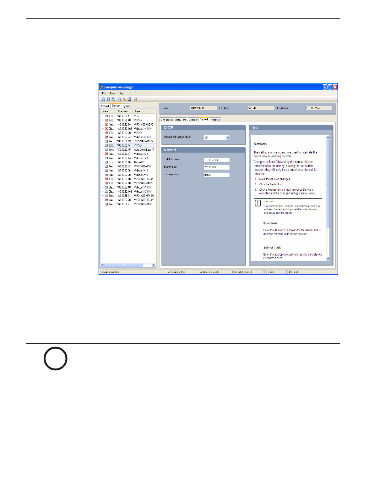
5.18 Network
The settings on this page are used to integrate the VIP XD into an existing network.
Some changes only take effect after the unit is rebooted. In this case, the Set button changes
to Set and Reboot.
1. Make the desired changes.
2. Click the Set and Reboot button. The VIP XD is rebooted and the changed settings are
activated.
DOC | V4.0 | 2009.06 Installation and Operating Manual Bosch Security Systems
Page 45

VIP XD Configuration Using a Web Browser | en 45
!
!
CAUTION!
If you change the IP address, subnet mask or gateway address, the VIP XD is only available
under the new addresses after the reboot.
Automatic IP assignment
If a DHCP server is employed in the network for the dynamic assignment of IP addresses, you
can activate acceptance of IP addresses automatically assigned to the VIP XD.
Certain applications (VIDOS, Bosch Video Management System, Archive Player, Configuration
Manager) use the IP address for the unique assignment of the unit. If you use these
applications, the DHCP server must support the fixed assignment between IP address and
MAC address, and must be appropriately set up so that, once an IP address is assigned, it is
retained each time the system is rebooted.
IP address
Enter the desired IP address for the VIP XD in this field. The IP address must be valid for the
network.
Subnet mask
Enter the appropriate subnet mask for the selected IP address here.
Gateway address
If you want the unit to establish a connection to a remote location in a different subnet, enter
the IP address of the gateway here. Otherwise leave the box blank (0.0.0.0).
DNS server address
The unit can use a DNS server to trigger an address specified as a name. Enter the IP address
of the DNS server here.
Video transmission
If the unit is operated behind a firewall, TCP (HTTP port) should be selected as the transfer
protocol. For use in a local network, select UDP.
CAUTION!
Multicast operation is only possible with the UDP protocol. The TCP protocol does not
support multicast connections.
The MTU value in UDP mode is 1,514 bytes.
HTTP browser port
Select a different HTTP browser port from the list if required. The default HTTP port is 80. If
you want to allow only secure connections via HTTPS, you must deactivate the HTTP port. In
this case, select Off.
HTTPS browser port
If you wish to allow browser access on the network via a secure connection, select an HTTPS
browser port from the list if necessary. The default HTTPS port is 443. Select the Off option
to deactivate HTTPS ports; only unsecured connections will now be possible.
The VIP XD uses the TLS 1.0 encryption protocol. You may have to activate this protocol via
your browser configuration. You must also activate the protocol for the Java applications (via
the Java control panel in the Windows control panel).
Bosch Security Systems Installation and Operating Manual DOC | V4.0 | 2009.06
Page 46

46 en | Configuration Using a Web Browser VIP XD
i
i
NOTICE!
If you want to allow only secure connections with SSL encryption, you must select the Off
option for each of the parameters HTTP browser port, RCP+ port 1756 and Telnet support.
This deactivates all unsecured connections. Connections will then only be possible via the
HTTPS port.
You can activate and configure encryption of the media data (video, audio and metadata) on
the Encryption page (see Section 5.20 Encryption, page 48).
RCP+ port 1756
To exchange connection data, you can activate the unsecured RCP+ port 1756. If you want
connection data to be transmitted only when encrypted, select the Off option to deactivate
the port.
Telnet support
If you want to allow only secure connections with encrypted data transmission, you must
select the Off option to deactivate Telnet support. The unit will then no longer be accessible
using the Telnet protocol.
Interface mode ETH
If necessary, select the Ethernet link type for the ETH interface. Depending on the unit
connected, it may be necessary to select a special operation type.
Network MSS (Byte)
You can set the maximum segment size for the IP packet's user data. This gives you the option
to adjust the size of the data packets to the network environment and to optimize data
transmission. Please comply with the MTU value of 1,514 bytes in UDP mode.
Enable DynDNS
DynDNS.org is a DNS hosting service that stores IP addresses in a database ready for use. It
allows you to select the VIP XD via the Internet using a host name, without having to know the
current IP address of the unit. You can enable this service here. To do this, you must have an
account with DynDNS.org and you must have registered the required host name for the unit
on that site.
NOTICE!
Information about the service, registration process and available host names can be found at
DynDNS.org.
Host name
Enter the host name registered on DynDNS.org for the VIP XD here.
User name
Enter the user name you registered at DynDNS.org here.
Password
Enter the password you registered at DynDNS.org here.
Force registration now
You can force the registration by transferring the IP address to the DynDNS server. Entries
that change frequently are not provided in the Domain Name System. It is a good idea to force
the registration when you are setting up the device for the first time. Only use this function
when necessary and no more than once a day, to avoid the possibility of being blocked by the
service provider. To transfer the IP address of the VIP XD, click the Register button.
DOC | V4.0 | 2009.06 Installation and Operating Manual Bosch Security Systems
Page 47

VIP XD Configuration Using a Web Browser | en 47
Status
The status of the DynDNS function is displayed here for information purposes. You cannot
change any of these settings.
5.19 Advanced
The settings on this page are used to implement advanced settings for the network.
Some changes only take effect after the unit is rebooted. In this case, the Set button changes
to Set and Reboot.
1. Make the desired changes.
2. Click the Set and Reboot button. The VIP XD is rebooted and the changed settings are
activated.
SNMP
The VIP XD supports the SNMP V2 (Simple Network Management Protocol) for managing and
monitoring network components, and can send SNMP messages (traps) to IP addresses. The
unit supports SNMP MIB II in the unified code. If you wish to send SNMP traps, enter the IP
addresses of one or two required target units here.
If you select On for the SNMP parameter and do not enter an SNMP host address, the VIP XD
does not send them automatically, but only replies to SNMP requests. If you enter one or two
SNMP host addresses, SNMP traps are sent automatically. Select Off to deactivate the SNMP
function.
1. SNMP host address / 2. SNMP host address
If you wish to send SNMP traps automatically, enter the IP addresses of one or two required
target units here.
Bosch Security Systems Installation and Operating Manual DOC | V4.0 | 2009.06
Page 48

48 en | Configuration Using a Web Browser VIP XD
SNMP traps
You can select which traps are to be sent.
1. Click Select. A list is opened.
2. Click the checkboxes to select the required traps. All the checked traps will be sent.
3. Click OK to apply the selection.
Authentication
If a RADIUS server is employed in the network for managing access rights, authentication
must be activated here to allow communication with the unit. The RADIUS server must also
contain the corresponding data.
To configure the unit, you must connect the VIP XD directly to a computer using a network
cable. This is because communication via the network is not enabled until the Identity and
Password parameters have been set and successfully authenticated.
Identity
Enter the name that the RADIUS server is to use for identifying the VIP XD.
Password
Enter the password that is stored in the RADIUS server.
RTSP port
If necessary, select a different port for the exchange of the RTSP data from the list. The
standard RTSP port is 554. Select Off to deactivate the RTSP function.
5.20 Encryption
A special license, with which you will receive a corresponding activation key, is required to
encrypt user data. You can enter the activation key to release the function on the Licenses
page (see Section 5.22 Licenses, page 51).
DOC | V4.0 | 2009.06 Installation and Operating Manual Bosch Security Systems
Page 49

VIP XD Configuration Using a Web Browser | en 49
!
5.21 Maintenance
Firmware
The VIP XD is designed in such a way that its functions and parameters can be updated with
firmware. To do this, transfer the current firmware package to the unit via the selected
network. It will then be automatically installed there.
In this way, a VIP XD can be serviced and updated remotely without a technician having to
change the installation on site.
You obtain the current firmware from your customer service or from the download area on our
Internet site.
CAUTION!
Before launching the firmware upload make sure that you have selected the correct upload
file. Uploading the wrong files can result in the unit no longer being addressable, in which
case you must replace the unit.
You should never interrupt the installation of firmware. An interruption can lead to the flashEPROM being incorrectly programmed. This in turn can result in the unit no longer being
addressable, in which case it will have to be replaced. Even changing to another page or
closing the browser window leads to an interruption.
1. First store the firmware file on your hard drive.
2. Enter the full path of the firmware file in the field or click Browse to locate and select the
file.
3. Next, click Upload to begin transferring the file to the unit. The progress bar allows you
to monitor the transfer.
The new firmware is unpacked and the Flash EPROM is reprogrammed. The time remaining is
shown by the message going to reset Reconnecting in ... seconds. The unit reboots
automatically once the upload has successfully completed.
If the operating status LED lights up red, the upload has failed and must be repeated. To
perform the upload you must now switch to a special page:
1. In the address bar of your browser, enter /main.htm after the IP address of the VIP XD
(for example 192.168.0.32/main.htm).
2. Repeat the upload.
Bosch Security Systems Installation and Operating Manual DOC | V4.0 | 2009.06
Page 50

50 en | Configuration Using a Web Browser VIP XD
i
Configuration
You can save configuration data for the VIP XD on a computer and then load saved
configuration data from a computer to the unit.
Upload
1. Enter the full path of the file to upload or click Browse to select the required file.
2. Make certain that the file to be loaded comes from the same unit type as the unit you
want to configure.
3. Next, click Upload to begin transferring the file to the unit. The progress bar allows you
to monitor the transfer.
Once the upload is complete, the new configuration is activated. The time remaining is shown
by the message going to reset Reconnecting in ... seconds. The unit reboots automatically
once the upload has successfully completed.
Download
1. Click the Download button. A dialog box opens.
2. Follow the on-screen instructions to save the current settings.
SSL certificate
To be able to work with an SSL encrypted data connection, both ends of a connection must
hold the relevant certificates. You can upload the SSL certificate, comprising one or multiple
files, onto the VIP XD.
If you wish to upload multiple files onto the VIP XD, you must select them consecutively.
NOTICE!
The certificate must be created in the format *.pem so that it can be accepted by the unit.
1. Enter the full path of the file to upload or click Browse to select the required file.
2. Next, click Upload to begin transferring the file to the unit.
3. Once all files have been successfully uploaded, the unit must be rebooted. In the address
bar of your browser, enter /reset after the IP address of the VIP XD (for example
192.168.0.32/reset).
The new SSL certificate is valid.
Decoder logo
If no video camera is selected, the decoder logo is displayed instead of the camera image. It is
possible to create your own decoder logo and load it onto the VIP XD.
To create the logo, you need a special program, which is available from Bosch Security
Systems. Standard image formats are not supported for the decoder logo.
1. Enter the full path of the file to upload or click Browse to select the required file.
2. Click Upload to transfer the file to the unit.
Delete decoder logo
Click Delete decoder logo to remove the decoder logo.
Maintenance log
You can download an internal maintenance log from the unit to send it to Customer Service
for support purposes. Click Download and select a storage location for the file.
DOC | V4.0 | 2009.06 Installation and Operating Manual Bosch Security Systems
Page 51

VIP XD Configuration Using a Web Browser | en 51
i
i
5.22 Licenses
You can enter the activation key to release additional functions or software modules.
NOTICE!
The activation key cannot be deactivated again and is not transferable to other units.
5.23 System Overview
The data on this page are for information purposes only and cannot be changed. Keep a
record of these numbers in case technical assistance is required.
NOTICE!
You can select all required text on this page with the mouse and copy it to the clipboard with
the [Ctrl]+[C] key combination, for example if you want to send it via e-mail.
Bosch Security Systems Installation and Operating Manual DOC | V4.0 | 2009.06
Page 52

52 en | Configuration Using a Web Browser VIP XD
5.24 Function Test
The VIP XD offers a variety of configuration options. You should therefore check that it is
functioning correctly after installation and configuration.
The function test is the only way to ensure that the VIP XD operates as expected in the event
of an alarm.
Your check should include the following functions:
– Can the VIP XD be called up remotely?
– Does the VIP XD transmit all the required data?
– Does the VIP XD respond to alarm events as required?
– Is it possible to control peripherals if necessary?
DOC | V4.0 | 2009.06 Installation and Operating Manual Bosch Security Systems
Page 53

VIP XD Operation | en 53
i
6 Operation
6.1 Connecting
A computer with Microsoft Internet Explorer (version 6.0 or higher) can establish a
connection to a compatible video server and play back the live images received on the monitor
connected to the VIP XD.
System Requirements
– Computer with Windows XP or Windows Vista operating system
– Network access (Intranet or Internet)
– Microsoft Internet Explorer (version 6.0 or higher)
– Screen resolution 1,024 × 768 pixels
– 16- or 32-bit color depth
– Installed Sun JVM
NOTICE!
Also note the information in the System Requirements document on the product CD
supplied. If necessary, you can install the required programs and controls from the product
CD supplied (see Section 3.1 Scope of Delivery, page 9).
The Web browser must be configured to enable Cookies to be set from the IP address of the
unit.
In Windows Vista, deactivate protected mode on the Security tab under Internet Options.
You can find notes on using Microsoft Internet Explorer in the online Help in Internet Explorer.
Installing MPEG ActiveX
Suitable MPEG ActiveX software must be installed on the computer to allow the live video
images to be played back. If necessary, you can install the program from the product CD
supplied.
1. Insert the product CD into the computer's CD-ROM drive. If the CD does not start
automatically, open the root directory of the CD in Windows Explorer and double-click
MPEGAx.exe.
2. Follow the on-screen instructions.
Bosch Security Systems Installation and Operating Manual DOC | V4.0 | 2009.06
Page 54

54 en | Operation VIP XD
Establishing the Connection
The VIP XD must be assigned a valid IP address to operate on your network.
The following default address is preset at the factory: 192.168.0.1
1. Start the Web browser.
2. Enter the IP address of the VIP XD as the URL. The connection is established and after a
short time you will see the CONNECTIONS page.
Maximum Number of Connections
If you do not connect, the unit may have reached its maximum number of connections.
Depending on the unit and network configuration, each VIP XD can have up to 25 Web
browser connections or up to 50 connections via VIDOS or Bosch Video Management System.
DOC | V4.0 | 2009.06 Installation and Operating Manual Bosch Security Systems
Page 55

VIP XD Operation | en 55
i
Protected VIP XD
If the VIP XD is password protected against unauthorized access, the Web browser displays a
corresponding message and prompts you to enter the password when you attempt to access
protected areas.
NOTICE!
The VIP XD offers the option to limit the extent of access using various authorization levels
(see Section 5.4 Password, page 25).
1. Enter the user name and associated password in the corresponding text fields.
2. Click OK. If the password is entered correctly, the Web browser displays the page that
was called up.
Protected Network
If a RADIUS server is employed in the network for managing access rights (802.1x
authentication), the VIP XD must be configured accordingly, otherwise no communication is
possible (see Section Authentication, page 48).
Bosch Security Systems Installation and Operating Manual DOC | V4.0 | 2009.06
Page 56

56 en | Operation VIP XD
6.2 The CONNECTIONS Page
Once the connection is established, the Web browser first displays the CONNECTIONS page
and the VIP XD automatically browses the network for available senders.
Preview
In this area you can select one of the video sources found in the network. You see a snapshot
of the video image from the selected source. Besides the unit name, the snapshot provides an
additional means of identifying the sender.
Monitor
As soon as a connection is established, you see the video image from the connected sender.
The image is refreshed around once per second.
DOC | V4.0 | 2009.06 Installation and Operating Manual Bosch Security Systems
Page 57

VIP XD Operation | en 57
i
i
6.3 Connections Between the Sender and Receiver
When you open the CONNECTIONS page, the VIP XD automatically scans the network for
available senders. As soon as a sender is found in the network, the VIP XD displays a JPEG
snapshot from that sender. All senders found are listed in the Video sources list field.
NOTICE!
The sender and receiver must be located in the same subnet to establish a hardware
connection.
Establishing the Connection
NOTICE!
If you do not connect, the unit may have reached its maximum number of connections. The
maximum number of connections depends on the unit and network configuration.
The Serial data and Audio checkboxes must be selected before the connection is made in
order to activate data and audio transmission. The window displays a green loudspeaker icon
in the bottom right corner of the video image the first time an audio connection is made. This
icon indicates which sender is holding the active audio link.
1. Choose the desired sender from the Video sources list field.
2. If necessary, enter the password.
3. Click OK. If the password is correct, a JPEG snapshot from the selected video source
appears in the Preview area.
4. If the sender is a multi-channel unit, for example a VideoJet X40, you can set the Video
input for playback.
5. If the sender works with Dual Streaming, for example a VIP X1600, you can select the
Stream for playback.
6. Check the Serial data checkbox if you also want to transmit transparent data. Ensure
that the sender and receiver are correctly configured for data transmission.
7. Check the Audio checkbox if you also want to transmit audio data. Ensure that the
sender and receiver are correctly configured for audio transmission.
8. Click the appropriate checkbox again to deactivate the data or audio connection.
9. Click the MPEG-2 ->, MPEG-4 SH++ -> or H.264 -> button to start displaying the video
images on the connected monitor. In the Monitor area you will see the video image from
the connected sender. The image is refreshed around once per second.
Bosch Security Systems Installation and Operating Manual DOC | V4.0 | 2009.06
Page 58

58 en | Operation VIP XD
Controlling Connections
You can control the selected connections and the monitor display using the buttons above the
video image in the Monitor area. The buttons have the following functions:
Switch to the previous connection in the connection history.
Switch to the next connection in the connection history.
Single view display
Quad view
Activate and deactivate auto-connect (see Section Auto-connect, page 36).
Disconnect and end display of video images on the connected monitor.
Update display of video image.
Switch to the start-up connection (first connection after selecting VIP XD).
Selecting Decoder for Quad View
When selecting Quad view, you can select the appropriate decoder for the display. This allows
you to freely assign in which quadrant the relevant video image is to be displayed.
1. In the Monitor area, click the button for Quad view.
2. Click the desired quadrant. The selected quadrant is marked by a red frame.
3. Establish the connection and start the display on the monitor (see Section Establishing
the Connection, page 57). The video images are displayed in the selected quadrant.
Multicast scan
You can use the Multicast scan to search for video sources outside the subnet in which the
VIP XD is located. Check the box in the Preview area to activate the Multicast scan.
DOC | V4.0 | 2009.06 Installation and Operating Manual Bosch Security Systems
Page 59

VIP XD Operation | en 59
i
i
6.4 Hardware Connections Between Video Servers
You can easily connect a VIP XD with a connected monitor as a receiver, together with a
compatible sender (for example VIP X1600) with a connected camera via an Ethernet
network. In this way it is possible to cover long distances without the need for major
installation or cabling work.
NOTICE!
The sender and receiver must be located in the same subnet to establish a hardware
connection.
Installation
Compatible video servers are designed to connect to one another automatically, provided
they are correctly configured. They only need to be part of a closed network. Proceed as
follows to install the units:
1. Connect the units to the closed network using Ethernet cables.
2. Connect them to the power supply.
NOTICE!
Make sure that the units are configured for the network environment and that the correct IP
address for the remote location to be contacted in the event of an alarm is set on the Alarm
Connections configuration page (see Section 5.11 Alarm Connections, page 34).
Connecting
There are three options for establishing a connection between a sender and a compatible
receiver in a closed network:
– an alarm,
– a terminal program, or
–Internet Explorer.
Connecting on Alarm
With the appropriate configuration, a connection between a sender and a receiver is made
automatically when an alarm is triggered (see Section 5.11 Alarm Connections, page 34). After
a short time the live video image from the sender appears on the connected monitor.
This option can also be used to connect a sender and a compatible receiver using a switch
connected to the alarm input. You do not need a computer to make the connection in this
case.
Connecting with a Terminal Program
Various requirements must be met in order to operate with a terminal program (see
Section 8.7 Communication with Terminal Program, page 67).
1. Start the terminal program and enter the command 1 in the main menu to switch to the
IP menu.
2. Enter the command 4 in the IP menu to change the remote IP address, then enter the IP
address of the unit you wish to connect to.
3. Enter the command 0 to return to the main menu and then enter the command 4 to
switch to the Rcp+ menu.
4. In the Rcp+ menu, enter the command 5 to activate the automatic connection.
Closing the Connection with a Terminal Program
1. Start the terminal program and enter the command 4 in the main menu to switch to the
Rcp+ menu.
2. In the Rcp+ menu, enter the command 5 to deactivate the automatic connection.
Bosch Security Systems Installation and Operating Manual DOC | V4.0 | 2009.06
Page 60

60 en | Operation VIP XD
6.5 Operation with Management Software
The use of management software such as VIDOS is recommended for operating larger systems
with multiple senders and receivers.
VIDOS is a software package for operating, controlling and managing CCTV installations (such
as surveillance systems) at remote locations. It runs under Microsoft Windows operating
systems. It is primarily designed for decoding video, audio and control data received from a
remote sender and for the convenient control of hardware connections.
Many options are provided for operation and configuration when using a VIP XD with VIDOS.
Please refer to the software documentation for more details.
Another program that supports the VIP XD is Bosch Video Management System. Bosch Video
Management System is an IP video security solution that enables the seamless management
of digital video, audio and data over any IP network. It was developed for use with Bosch
CCTV products as one component of an extensive video security management system. It
allows you to integrate your existing components into a simple-to-control system or into the
entire Bosch range, benefiting from a complete security solution based on the latest
technology and years of experience.
DOC | V4.0 | 2009.06 Installation and Operating Manual Bosch Security Systems
Page 61

VIP XD Maintenance and Upgrades | en 61
!
i
7 Maintenance and Upgrades
7.1 Testing the Network Connection
You can use the ping command to check the connection between two IP addresses. This
allows you to test whether a unit in the network is active.
1. Open the DOS command prompt.
2. Type ping followed by the IP address of the unit.
If the unit is found, the response appears as Reply from ... followed by the number of bytes
sent and the transmission time in milliseconds. If not, the unit cannot be accessed over the
network. This might be because:
– The unit is not correctly connected to the network. Check the cable connections in this
case.
– The unit is not correctly integrated into the network. Check the IP address, subnet mask
and gateway address.
7.2 Unit Reset
You can use the Factory Reset button to restore the unit to its original settings. Any changes
to the settings are overwritten by the factory defaults. A reset may be necessary, for example,
if the unit has invalid settings that prevent it from functioning as desired.
CAUTION!
All configured settings will be discarded during a reset.
If necessary, back up the current configuration using the Download button on the
Maintenance configuration page (see Section 5.21 Maintenance, page 49).
NOTICE!
After a reset, the unit can only be addressed via the factory default IP address. The IP address
can be changed as described in the Installation chapter (see Section 4.4 Setup Using the
Configuration Manager, page 19).
1. If necessary, back up the current configuration using the Download button on the
Maintenance configuration page (see Section 5.21 Maintenance, page 49).
2. Using a pointed object, press the factory reset button until the operating status LED
flashes red (see Section 3.5 Connections on the Rear Panel, page 14). All settings will
revert to their defaults.
3. Change the IP address of the VIP XD if necessary.
4. Configure the unit to meet your requirements.
Bosch Security Systems Installation and Operating Manual DOC | V4.0 | 2009.06
Page 62

62 en | Maintenance and Upgrades VIP XD
!
7.3 Repairs
CAUTION!
Never open the housing of the VIP XD.
The unit does not contain any user-serviceable parts.
Ensure that all maintenance or repair work is carried out only by qualified personnel
(electrical engineers or network technology specialists). In case of doubt, contact your
dealer's technical service center.
7.4 Transfer and Disposal
The VIP XD should only be passed on together with this installation and operating manual.
Your Bosch product is designed and manufactured with high-quality materials and
components which can be recycled and reused.
This symbol means that electrical and electronic equipment, at their end-of-life, should be
disposed of separately from your household waste.
In the European Union, there are separate collection systems for used electrical and
electronic products. Please dispose of this equipment at your local community waste
collection/recycling center.
DOC | V4.0 | 2009.06 Installation and Operating Manual Bosch Security Systems
Page 63

VIP XD Appendix | en 63
8 Appendix
8.1 Troubleshooting
If you are unable to resolve a malfunction, please contact your supplier or systems integrator,
or go directly to Bosch Security Systems Customer Service.
You can view a range of information about your unit version on the System Overview page
(see Section 5.23 System Overview, page 51). Make a note of this information before
contacting Customer Service. You can download an internal maintenance log from the unit on
the Maintenance page if you wish to send it to Customer Service by e-mail (see
Section Maintenance log, page 50).
The following table is intended to help you identify the causes of malfunctions and correct
them where possible.
Malfunction Possible causes Recommended solution
No connection between
the unit and terminal
program.
No image on the monitor. Monitor error. Connect local camera or other
No connection
established, no image
transmission.
Incorrect cable connections. Check all cables, plugs,
contacts, terminals and
connections.
The computer's serial interface
is not connected.
Interface parameters do not
match.
Faulty cable connections. Check all cables, plugs, contacts
The unit's configuration. Check all configuration
Faulty installation. Check all cables, plugs, contacts
Wrong IP address. Check the IP addresses
Faulty data transmission within
the LAN.
The maximum number of
connections has been reached.
Check the other serial interface.
If necessary select a different
interface and make sure that the
computer's interface parameters
match those of the unit. Try the
following standard parameters:
19,200 baud, 8 data bits, no
parity, 1 stop bit. Next,
disconnect the unit from the
power supply and reconnect it
again after a few seconds.
video source to the monitor and
check the monitor function.
and connections.
parameters.
and connections.
(terminal program).
Check the data transmission
with ping.
Wait until there is a free
connection and then call the
sender again.
Bosch Security Systems Installation and Operating Manual DOC | V4.0 | 2009.06
Page 64

64 en | Appendix VIP XD
Malfunction Possible causes Recommended solution
No audio transmission to
remote station.
Hardware fault. Check that all connected audio
units are operating correctly.
Faulty cable connections. Check all cables, plugs, contacts
and connections.
Incorrect configuration. Check the audio parameters on
the Audio configuration page.
The audio voice connection is
already in use by another
Wait until the connection is free
and then call the sender again.
receiver.
The unit does not report
an alarm.
Alarm source is not selected. Select possible alarm sources on
the Alarm Inputs configuration
page.
No alarm response specified. Specify the desired alarm
response on the Alarm
Connections configuration page,
change the IP address if
necessary.
Control of cameras or
other units is not
possible.
The cable connection between
the serial interface and the
connected unit is not correct.
The interface parameters do not
match those of the other unit
Check all cable connections and
ensure all plugs are properly
fitted.
Make sure that the settings of all
units involved are compatible.
connected.
The unit is not
operational after a
firmware upload.
Power failure during
programming by firmware file.
Have the unit checked by
Customer Service and replace if
necessary.
Incorrect firmware file. Enter the IP address of the unit
followed by /main.htm in your
Web browser and repeat the
upload.
Placeholders with a red
cross are displayed
Sun JVM is not installed on the
computer or is not enabled.
Install Sun JVM from the
product CD.
instead of the ActiveX
components.
Web browser contains
empty fields.
Active proxy server in network. Create a rule in the local
computer's proxy settings to
exclude local IP addresses.
If a sender is connected
Auto-connect configured. Deactivate auto-connect.
to the receiver, the first
connection remains.
DOC | V4.0 | 2009.06 Installation and Operating Manual Bosch Security Systems
Page 65

VIP XD Appendix | en 65
8.2 LEDs
The VIP XD network video server has a number of LEDs on its rear panel that show the
operating status and can give indications of possible malfunctions:
Operating Status LED
Does not light up: VIP XD is switched off.
Lights up green: VIP XD is switched on.
Flashes green: The VIP XD is being accessed.
Flashes red: Startup in progress.
Lights up red: VIP XD is faulty, for example following failed firmware
upload.
LED L
Does not light up: No network connection.
Lights up green: Network connection established.
LED T
Flashes orange: Data being transmitted over the network.
8.3 Processor Load
If the VIP XD is accessed via the Web browser, you will see the processor load indicator in the
top left of the window next to the manufacturer's logo.
Moving the mouse cursor over the graphic indicator displays the status of the processor
together with the numerical values. This information may help you with troubleshooting or
fine tuning the unit.
8.4 Network Connection
You can display information about the network connection. To do this, move the cursor over
the i icon.
Link Ethernet link type
UL Uplink, speed of the outgoing data traffic
DL Downlink, speed of the incoming data traffic
Bosch Security Systems Installation and Operating Manual DOC | V4.0 | 2009.06
Page 66

66 en | Appendix VIP XD
8.5 Serial Interface
Options for using the serial interface include transferring transparent data, controlling
connected units or operating the unit with a terminal program.
The serial interface supports the RS-232/RS-422/RS-485 transmission standards. The mode
used depends on the current configuration (see Section 5.17 COM1, page 43). Connection is
via the terminal block.
8.6 Terminal Block
The terminal block has several contacts for:
– 4 alarm inputs
–1 relay output
– Serial data transmission
Pin Assignment
The pin assignment of the serial interface depends on the interface mode used (see
Section 5.17 COM1, page 43).
Contact RS-232 mode RS-422 mode RS-485 mode
CTS CTS (clear to send) RxD- (receive data minus) Data-
RTS RTS (ready to send) TxD- (transmit data minus)
RXD RxD (receive data) RxD+ (receive data plus) Data+
TXD TxD (transmit data) TxD+ (transmit data plus)
GND GND (ground) — —
Contact Function
IN1 Input alarm 1
IN2 Input alarm 2
IN3 Input alarm 3
IN4 Input alarm 4
GND Ground
R Relay Output
+ 12 to 24 V DC (power supply)
–Ground
Connect each alarm input to a ground contact (GND) when connecting alarm inputs.
DOC | V4.0 | 2009.06 Installation and Operating Manual Bosch Security Systems
Page 67

VIP XD Appendix | en 67
i
8.7 Communication with Terminal Program
Data Terminal
If a VIP XD cannot be found in the network or the connection to the network is interrupted,
you can connect a data terminal to the VIP XD for initial setup and setting of important
parameters. The data terminal consists of a computer with a terminal program.
You require a serial transmission cable with a 9-pin Sub-D plug to connect to the computer
and open ends for connection to the terminal block of the VIP XD (see Section Pin Assignment,
page 66).
HyperTerminal, a communications accessory included with Microsoft Windows, can be used
as the terminal program.
NOTICE!
Information on installing and using HyperTerminal can be found in the manuals or in the online
help for MS Windows.
1. Disconnect the VIP XD from the Ethernet network before working with the terminal
program.
2. Connect the serial interface of the VIP XD using any available serial interface on the
computer.
Configuring the Terminal
Before the terminal program can communicate with the VIP XD, the transmission parameters
must be matched. Make the following settings for the terminal program:
– 19,200 bps
– 8 data bits
– No parity check
–1 stop bit
– No protocol
Command Inputs
After the connection has been established, you must log on to the VIP XD to access the main
menu. Other submenus and functions can be accessed using the on-screen commands.
1. If necessary, turn off the local echo so that entered values are not repeated on the
display.
2. Enter one command at a time.
3. When you have entered a value (such as an IP address), check the characters you have
entered before pressing Enter to transfer the values to the VIP XD.
Bosch Security Systems Installation and Operating Manual DOC | V4.0 | 2009.06
Page 68

68 en | Appendix VIP XD
i
Assigning an IP Address
Before you can operate a VIP XD in your network you must first assign it an IP address that is
valid for your network.
The following default address is preset at the factory: 192.168.0.1
1. Start a terminal program such as HyperTerminal.
2. Enter the user name service. The terminal program displays the main menu.
3. Enter command 1 to open the IP menu.
4. Enter 1 again. The terminal program displays the current IP address and prompts you to
enter a new IP address.
5. Enter the desired IP address and press Enter. The terminal program displays the new IP
address.
6. Use the displayed commands for any additional settings you require.
NOTICE!
You must reboot to activate the new IP address, a new subnet mask or a gateway IP address.
Reboot
Briefly interrupt the power supply to the VIP XD for a reboot (disconnect the power supply
unit from the mains supply and switch on again after a few seconds).
Additional Parameters
You can use the terminal program to check other basic parameters and modify them where
necessary. Use the on-screen commands in the various submenus to do this.
DOC | V4.0 | 2009.06 Installation and Operating Manual Bosch Security Systems
Page 69

VIP XD Appendix | en 69
8.8 Copyrights
The firmware 4.0 uses the fonts "Adobe-Helvetica-Bold-R-Normal--24-240-75-75-P-138ISO10646-1" and "Adobe-Helvetica-Bold-R-Normal--12-120-75-75-P-70-ISO10646-1" under the
following copyright:
Copyright 1984-1989, 1994 Adobe Systems Incorporated.
Copyright 1988, 1994 Digital Equipment Corporation.
Permission to use, copy, modify, distribute and sell this software and its documentation for
any purpose and without fee is hereby granted, provided that the above copyright notices
appear in all copies and that both those copyright notices and this permission notice appear
in supporting documentation, and that the names of Adobe Systems and Digital Equipment
Corporation not be used in advertising or publicity pertaining to distribution of the software
without specific, written prior permission.
This software is based in part on the work of the Independent JPEG Group.
Bosch Security Systems Installation and Operating Manual DOC | V4.0 | 2009.06
Page 70

70 en | Appendix VIP XD
DOC | V4.0 | 2009.06 Installation and Operating Manual Bosch Security Systems
Page 71

VIP XD Specifications | en 71
9 Specifications
9.1 Unit
Operating voltage 12 to 24 V DC, power supply unit with various primary
adapters included
Power consumption Approx. 7 W
LAN interfaces 1 × Ethernet 10/100 Base-T, automatic adjustment,
half/full duplex, RJ45
Data interfaces 1 × RS-232/RS-422/RS-485, bidirectional, push-in terminal
Alarm inputs 4 × push-in terminals (non-isolated closing contact),
maximum activation resistance 10 Ohm
Relay output 1 × push-in terminal, 30 V
Video outputs 1 × BNC, 1.0 V
, 75 Ohm, PAL/NTSC
p-p
1 × Sub-D 15-pin, VGA/SVGA, 1.0 V
Displays 3 × LED (operating voltage, network connection, data
transfer) on rear panel
Operating conditions Temperature: 0 to +50 °C / +32 to +122 °F
relative humidity: 0 to 95%, non-condensing
Approvals IEC 60950; UL 1950; AS/NZS 3548; EN 55103-1, -2;
EN 55130-4; EN 55022; EN 55024; EN 61000-3-2;
EN 61000-3-3; FCC 47 CFR Chapter 1 Part 15
Dimensions (H×W×D) 85×107×26mm / 3.35×4.21×1.02in,
including feet and connections
Weight Approx. 300 g (0.5 lb)
, 2 A (SELV), 2 contacts
p-p
, RGB analog
p-p
Audio Version Only:
Audio input 1 × 3.5 mm stereo socket
5.5 V
max., impedance 9 kOhm typ.
p-p
Audio output 1 × 3.5 mm stereo socket
3.0 V
max., impedance 16 kOhm min.
p-p
Microphone input 1 × push-in terminal, 2.8 V
impedance 2 kOhm typ., supply 2.3 V typ.
Loudspeaker output 1 × push-in terminal, 6 V
impedance 4 Ohm min.
max. at –20 dB,
p-p
max., RMS 1 W,
p-p
Bosch Security Systems Installation and Operating Manual DOC | V4.0 | 2009.06
Page 72

72 en | Specifications VIP XD
9.2 Protocols/Standards
Video standards PAL, NTSC
Video coding protocols MPEG-4, MPEG-2, H.264 BP+ (Baseline Profile plus)
Video data rate Up to 6 Mbps per stream
Image resolutions (PAL/NTSC) 704 × 576/480 pixels (4CIF/D1)
704 × 288/240 pixels (2CIF)
464 × 576/480 pixels (2/3 D1)
352 × 576/480 pixels (1/2 D1)
352 × 288/240 pixels (CIF)
176 × 144/120 pixels (QCIF)
Total delay 120 ms (PAL/NTSC, MPEG-4, no network delay)
Image refresh rate 25/30 ips max.
Network protocols RTP, Telnet, UDP, TCP, IP, HTTP, HTTPS, DHCP, IGMP V2,
IGMP V3, ICMP, ARP, SNTP, SNMP (V1/V2c/V3 MIB-II),
802.1x
Audio Version Only:
Audio coding protocol G.711, 300 Hz to 3.4 kHz
Audio sampling rate 8 kHz
Audio data rate 80 kbps
DOC | V4.0 | 2009.06 Installation and Operating Manual Bosch Security Systems
Page 73

VIP XD Glossary | en 73
10 Glossary
Symbols
10/100/1000 Base-T IEEE-802.3 specification for 10, 100 or 1000 Mbps Ethernet
802.1x The IEEE 802.1x standard provides a general method for authentication and authorization in
IEEE-802 networks. Authentication is carried out via the authenticator, which checks the
transmitted authentication information using an authentication server (see RADIUS server)
and approves or denies access to the offered services (LAN, VLAN or WLAN) accordingly.
A
ARP Address Resolution Protocol: a protocol for mapping MAC and IP addresses
B
Baud Unit of measurement for the speed of data transmission
bps Bits per second, the actual data rate
BVIP Bosch Video over IP unit
C
CABAC Context-based Adaptive Binary Arithmetic Coding; an effective way to compress binary data
without loss. In the video standard MPEG-4/Part10 (H.264/AVC), CABAC is characterized by
high picture quality, a high compression rate and high computing requirements.
CF CompactFlash; interface standard, for digital storage media amongst other things. Used in
computers in the form of CF cards, digital cameras and Personal Digital Assistants (PDA).
CIF Common Intermediate Format, video format with 352 × 288/240 pixels
D
DHCP Dynamic Host Configuration Protocol: uses an appropriate server to enable dynamic
assignment of an IP address and other configuration parameters to computers on a network
(Internet or LAN)
DNS Domain Name System, mainly used for converting domain names to IP addresses
DynDNS DNS hosting service that works according to RFC 2845 and stores the IP addresses of its
clients in a database, ready for use
F
FTP File Transfer Protocol
Full duplex Simultaneous data transmission in both directions (sending and receiving)
G
GBIC GigaBit Interface Converter; applied in network technology to render interfaces flexible, for
converting an electrical interface into an optical interface, for example. This enables flexible
Bosch Security Systems Installation and Operating Manual DOC | V4.0 | 2009.06
Page 74

74 en | Glossary VIP XD
operation of an interface as a Gigabit Ethernet via twisted-pair cables or fiber optic cables.
GOP Group of Pictures
H
H.264 Further development of video compression standard H.262 with higher image quality and high
compression factor
HTTP Hypertext Transfer Protocol: protocol for transmitting data over a network
HTTPS Hypertext Transfer Protocol Secure: encrypts and authenticates communication between Web
server and browser
I
ICMP Internet Control Message Protocol
ID Identification: a machine readable character string
IEEE Institute of Electrical and Electronics Engineers
IGMP Internet Group Management Protocol
Internet Protocol The main protocol used on the Internet, normally in conjunction with the Transfer Control
Protocol (TCP): TCP/IP
IP See Internet Protocol
IP address A 4-byte number uniquely defining each unit on the Internet. It is usually written in dotted
decimal notation, for example "209.130.2.193"
iSCSI Storage over IP process for storage networks; specifies how storage protocols are operated
over IP
ISDN Integrated Services Digital Network
J
JPEG An encoding process for still images (Joint Photographic Experts Group)
K
kbps Kilobits per second, the actual data rate
L
LAN See Local Area Network
Local Area Network A communications network serving users within a limited geographical area such as a building
or university campus. It is controlled by a network operating system and uses a transfer
protocol.
LUN Logical Unit Number; logical drive in iSCSI storage systems
M
MAC Media Access Control
DOC | V4.0 | 2009.06 Installation and Operating Manual Bosch Security Systems
Page 75

VIP XD Glossary | en 75
MIB Management Information Base; a collection of information for remote servicing using the
SNMP protocol
MPEG-2 Improved video/audio compression standard, compression on highest level allows images in
studio quality; now established as broadcast standard
MPEG-4 A further development of MPEG-2 designed for transmitting audiovisual data at very low
transfer rates (for example over the Internet)
MSS Maximum Segment Size; maximum byte figure for the user data in a data packet
N
Net mask A mask that explains which part of an IP address is the network address and which part is the
host address. It is usually written in dotted decimal notation, for example "255.255.255.192."
NTP Network Time Protocol; a standard for synchronizing computer system clocks via packet-
based communication networks. NTP uses the connectionless network protocol UDP. This
was developed specifically for enabling time to be reliably transmitted over networks with
variable packet runtime (Ping).
O
OF Optical Fiber; now used predominantly as the transmission medium for line-borne
telecommunication processes (glass fiber cable)
P
Parameters Values used for configuration
Q
QCIF Quarter CIF, video format with 176 × 144/120 pixels
R
RADIUS server Remote Authentication Dial-In User Service: a client/server protocol for the authentication,
authorization and accounting of users with dial-up connections on a computer network.
RADIUS is the de-facto standard for central authentication of dial-up connections via Modem,
ISDN, VPN, Wireless LAN (see 802.1x) and DSL.
RFC 868 A protocol for synchronizing computer clocks over the Internet
RS-232/-422/-485 Standards for serial data transmission
RTP Real-Time Transport Protocol; a transmission protocol for real-time video and audio
RTSP Real-Time Streaming Protocol; network protocol for controlling the continuous transmission
of audiovisual data (streams) or software over IP-based networks
S
SFP Small Form-factor Pluggable; small, standardized module for network connections, designed
as a plug connector for high-speed network connections
Bosch Security Systems Installation and Operating Manual DOC | V4.0 | 2009.06
Page 76

76 en | Glossary VIP XD
SNIA Storage Networking Industry Association; association of companies for defining the iSCSI
standard
SNMP Simple Network Management Protocol; a protocol for network management, for managing and
monitoring network components
SNTP Simple Network Time Protocol; a simplified version of NTP (see NTP)
SSL Secure Sockets Layer; an encryption protocol for data transmission in IP-based networks
Subnet mask See Net mask
T
TCP Transmission Control Protocol
Telnet Login protocol with which users can access a remote computer (Host) on the Internet
TLS Transport Layer Security; TLS 1.0 and 1.1 are the standard advanced developments of SSL 3.0
(see SSL)
TTL Time-To-Live; life cycle of a data packet in station transfers
U
UDP User Datagram Protocol
URL Uniform Resource Locator
UTP Unshielded Twisted Pair
W
WAN See Wide Area Network
Wide Area Network A long distance link used to extend or connect remotely located local area networks
DOC | V4.0 | 2009.06 Installation and Operating Manual Bosch Security Systems
Page 77

VIP XD Index | en 77
11 Index
A
Activation key 51
Alarm e-mail
Alarm input 17
Alarm sources
Audio connections 16
Audio stream on alarm 36
Audio transmission
Auto-connect 36
38
41
33
B
Baud rate 43
C
Changes 24
Checking network
Closing contact 17
COM1 43
Configuration
Configuration download 50
Configuration mode 24
Connect on alarm
Connecting 21, 59
Conventions 5
61
21, 50
34
D
Danger 7
Data bits 43
Data interface
Data terminal 67
Date 26
Date format
Daylight saving time 27
Device ID 25
Device name
Dome camera 17
DynDNS 46
17
26
25, 29
E
Echo 67
Electromagnetic compatibility 6
38
E-mail
Encryption protocol 45
EPROM
Establishing the connection
49
22, 54
F
Firewall 35, 45
Firmware upload
Front panel connections 13
Function test 52
49
G
Gateway 45
General password
35
H
HTTP port 45
HTTPS port
45
I
Identification 6, 25, 29
IEEE 802.1x
Installation 7
Installation conditions 15
48
Installation location
Interface 66
Interface mode
Internal clock 26
IP address
45, 68
L
Language 28
Licenses
Live video images 21, 53
Loudspeaker 16, 34
Low Voltage Directive
51
M
Main functions 12
Maintenance
Manufacturer logo 28
Microphone 16, 34
Monitor
MPEG ActiveX 21, 53
MTU value 45, 46
Multicast connection
Multicast function 11
7
16
N
Navigation 24
Network 17, 44, 47
Network connection 19, 65
Number of connections
O
Operation 7
P
Parameters 20, 68
Parity check 43
Password
Pin assignment 66
Playback button 58
Port
Power supply 7
Power switch 19
Processor load
Processor load indicator 65
Product name
Profile configuration
Protocol 43
23, 25, 26, 55
45
Q
Quad view 58
R
RADIUS 48
Reboot
Receiver password 35
Regulations
Relay output 18, 41
Repair 7, 62
Reset
20, 68
5
61
S
Safety 7
Scope of delivery
Screen resolution 10, 21, 53
Sender 11
15
43
6
45
22, 54
65
28
30
9
Bosch Security Systems Installation and Operating Manual DOC | V4.0 | 2009.06
Page 78

78 en | Index VIP XD
Serial number 6
Serial port function 43
Signal source
SMS 39
SNMP 47
SNTP server
SSL certificate 50
SSL encryption 36
Stop bits
Subnet mask 45
Summer time
Symbols
Synchronize 26
System requirements
17
27
43
27
5
10, 21, 53
T
TCP 35, 45
Terminal
Test
Time 26
Time server
Time server IP address
Time server protocol 27
Time signal 27
Time zone
TLS 45
Transmission interruptions 33
Transmission parameters
Transmission protocol 35, 45
Transmission rate
Transmission standards 17, 66
Transparent 43
Traps
Trigger 17
Trigger relay 42
43
52
27
27
26
67
43
48
U
UDP 35, 45
Unit date 26
Unit identification
Unit name
Unit reset 61
Unit time
URL
User name 26
25, 29
26
22, 54
25, 29
DOC | V4.0 | 2009.06 Installation and Operating Manual Bosch Security Systems
Page 79

Page 80

Bosc h Sicherheitssysteme GmbH
Robert-Koch-Straße 100
85521 Ottobrunn
Germany
Telefon 089 6290-0
Fax 089 6290-1020
www.bosch-securitysystems.com
© Bosch Sicherheitssysteme GmbH, 2009
 Loading...