

Bosch WBN 6000-30-H-E-N/L-S2400, Gaz 6000 W, WBN 6000-30-H-E-N-S2400, WBN 6000-30-H-E-L-S2400 Installation And Maintenance Instructions Manual
Installation and maintenance instructions for the contractor
Gas boiler
Gaz 6000 W
8 716 473 216-00.3O
WBN 6000-30-H-E-N/L-S2400
8 716 473 216 (2014/09) en

2 | Contents
Gaz 6000 W8 716 473 216 (2014/09)
Contents
1 Key to symbols and safety instructions . . . . . . . . . . . . . . . . . . . 3
1.1 Key to symbols . . . . . . . . . . . . . . . . . . . . . . . . . . . . . . . . . . 3
1.2 General safety instructions . . . . . . . . . . . . . . . . . . . . . . . . 3
2 Product details . . . . . . . . . . . . . . . . . . . . . . . . . . . . . . . . . . . . . . . . 4
2.1 Standard delivery . . . . . . . . . . . . . . . . . . . . . . . . . . . . . . . 4
2.2 Overview of the gas categories that can be used . . . . . . 4
2.3 Data plate . . . . . . . . . . . . . . . . . . . . . . . . . . . . . . . . . . . . . . 4
2.4 Description of appliance . . . . . . . . . . . . . . . . . . . . . . . . . . 4
2.5 Accessories . . . . . . . . . . . . . . . . . . . . . . . . . . . . . . . . . . . . 4
2.6 Dimensions and minimum clearances . . . . . . . . . . . . . . . 5
2.7 Appliance layout . . . . . . . . . . . . . . . . . . . . . . . . . . . . . . . . 6
2.8 Electrical wiring diagram . . . . . . . . . . . . . . . . . . . . . . . . . . 7
2.9 Technical data . . . . . . . . . . . . . . . . . . . . . . . . . . . . . . . . . . 8
3 Regulations . . . . . . . . . . . . . . . . . . . . . . . . . . . . . . . . . . . . . . . . . . 9
4 Flue gas routing . . . . . . . . . . . . . . . . . . . . . . . . . . . . . . . . . . . . . . . 9
4.1 Approved flue accessories . . . . . . . . . . . . . . . . . . . . . . . . 9
4.2 Installation instructions . . . . . . . . . . . . . . . . . . . . . . . . . . 9
5 Installation . . . . . . . . . . . . . . . . . . . . . . . . . . . . . . . . . . . . . . . . . . . 9
5.1 Important notes . . . . . . . . . . . . . . . . . . . . . . . . . . . . . . . . . 9
5.2 Checking the size of the expansion vessel . . . . . . . . . . 10
5.3 Siting the appliance . . . . . . . . . . . . . . . . . . . . . . . . . . . . 10
5.4 Fitting the appliance . . . . . . . . . . . . . . . . . . . . . . . . . . . 11
5.5 Installation of the supply pipes . . . . . . . . . . . . . . . . . . . 13
5.6 Checking the connections . . . . . . . . . . . . . . . . . . . . . . 13
5.7 Connecting the flue accessories . . . . . . . . . . . . . . . . . . 13
6 Electrical connections . . . . . . . . . . . . . . . . . . . . . . . . . . . . . . . 14
6.1 General notes . . . . . . . . . . . . . . . . . . . . . . . . . . . . . . . . 14
6.2 Connecting appliances with power cable and mains plug
14
6.3 Control unit terminals . . . . . . . . . . . . . . . . . . . . . . . . . . 14
6.3.1 Connecting the on/off controller or Open Therm controller
. . . . . . . . . . . . . . . . . . . . . . . . . . . . . . . . . . . . . . . . . . . . . 14
6.3.2 Replacing the power cable . . . . . . . . . . . . . . . . . . . . . . 15
7 Commissioning . . . . . . . . . . . . . . . . . . . . . . . . . . . . . . . . . . . . . 15
7.1 Displays . . . . . . . . . . . . . . . . . . . . . . . . . . . . . . . . . . . . . 16
7.2 Before commissioning . . . . . . . . . . . . . . . . . . . . . . . . . 16
7.3 Switching the appliance on/off . . . . . . . . . . . . . . . . . . . 16
7.4 Setting the maximum flow temperature . . . . . . . . . . . . 16
7.5 Setting the heating control unit . . . . . . . . . . . . . . . . . . 17
7.6 After commissioning . . . . . . . . . . . . . . . . . . . . . . . . . . . 17
7.7 Setting summer mode . . . . . . . . . . . . . . . . . . . . . . . . . . 17
7.8 Setting frost protection . . . . . . . . . . . . . . . . . . . . . . . . . 17
8 Heating pump . . . . . . . . . . . . . . . . . . . . . . . . . . . . . . . . . . . . . . . 17
8.1 Changing the heating circuit pump curve . . . . . . . . . . 17
8.2 Pump anti-seizing function . . . . . . . . . . . . . . . . . . . . . . 17
9 Service menu settings . . . . . . . . . . . . . . . . . . . . . . . . . . . . . . . 18
9.1 Operating the service menu . . . . . . . . . . . . . . . . . . . . . 18
9.2 Service functions overview . . . . . . . . . . . . . . . . . . . . . . 18
9.2.1 Menu 1 . . . . . . . . . . . . . . . . . . . . . . . . . . . . . . . . . . . . . . 18
9.2.2 Menu 2 . . . . . . . . . . . . . . . . . . . . . . . . . . . . . . . . . . . . . . 20
9.2.3 Menu 3 . . . . . . . . . . . . . . . . . . . . . . . . . . . . . . . . . . . . . . 21
10 Converting the appliance to different gas types . . . . . . . . . 22
10.1 Converting to a different gas type . . . . . . . . . . . . . . . . 22
10.2 Gas settings (natural and LPG) . . . . . . . . . . . . . . . . . . 22
10.2.1 Preparations . . . . . . . . . . . . . . . . . . . . . . . . . . . . . . . . . 22
10.2.2 Nozzle pressure setting method . . . . . . . . . . . . . . . . . . 22
11 Flue gas testing . . . . . . . . . . . . . . . . . . . . . . . . . . . . . . . . . . . . . 23
11.1 Setting the appliance output . . . . . . . . . . . . . . . . . . . . 23
11.2 Testing for flue gas tightness . . . . . . . . . . . . . . . . . . . . 23
11.3 Measuring CO level in flue gas . . . . . . . . . . . . . . . . . . . 23
11.4 Measuring flue gas loss . . . . . . . . . . . . . . . . . . . . . . . . . 23
12 Environment / disposal . . . . . . . . . . . . . . . . . . . . . . . . . . . . . . 24
13 Inspection/Maintenance . . . . . . . . . . . . . . . . . . . . . . . . . . . . . 24
13.1 Description of various maintenance operations . . . . . 24
13.1.1 Calling up the last fault saved . . . . . . . . . . . . . . . . . . . . 24
13.1.2 Opening the appliance . . . . . . . . . . . . . . . . . . . . . . . . . 24
13.1.3 Cleaning the burner pan, nozzles and burner . . . . . . . 26
13.1.4 Cleaning the heat exchanger . . . . . . . . . . . . . . . . . . . . 26
13.1.5 Checking the expansion vessel (also see page 10) . . . 26
13.1.6 Setting the heating system pressure . . . . . . . . . . . . . . 26
13.1.7 Checking electrical wiring . . . . . . . . . . . . . . . . . . . . . . . 26
13.2 Checklist for inspection and maintenance . . . . . . . . . 27
14 Displays . . . . . . . . . . . . . . . . . . . . . . . . . . . . . . . . . . . . . . . . . . . 28
15 Fault mode . . . . . . . . . . . . . . . . . . . . . . . . . . . . . . . . . . . . . . . . . 28
15.1 Troubleshooting . . . . . . . . . . . . . . . . . . . . . . . . . . . . . . 28
15.2 Faults that are shown on the display . . . . . . . . . . . . . . 29
15.3 Faults that are not shown on the display . . . . . . . . . . . 30
15.4 Sensor values . . . . . . . . . . . . . . . . . . . . . . . . . . . . . . . . 30
15.4.1 Flow temperature sensor . . . . . . . . . . . . . . . . . . . . . . . 30
16 Commissioning report for the appliance . . . . . . . . . . . . . . . . 31
Key to symbols and safety instructions | 3
8 716 473 216 (2014/09)Gaz 6000 W
1 Key to symbols and safety instructions
1.1 Key to symbols
Warnings
The following keywords are defined and can be used in this document:
• NOTICE indicates a situation that could result in damage to property
or equipment.
• CAUTION indicates a situation that could result in minor to medium
injury.
• WARNING indicates a situation that could result in severe injury or
death.
• DANGER indicates a situation that will result in severe injury or death.
Important information
Additional symbols
1.2 General safety instructions
These installation instructions are intended for gas fitters, plumbers,
heating engineers and electricians.
▶ Read any installation instructions (boiler, heating controls, etc.)
carefully before starting the installation.
▶ Observe the safety instructions and warnings.
▶ Observe national and regional regulations, technical rules and
guidelines.
▶ Record all work carried out.
If you smell gas
A gas leak could potentially cause an explosion. If you smell gas, observe
the following rules.
▶ Prevent flames or sparks:
– Do not smoke, use a lighter or strike matches.
– Do not operate any electrical switches or unplug any equipment.
– Do not use the telephone or ring doorbells.
▶ Turn off the gas at the meter.
▶ Open windows and doors.
▶ Warn your neighbours and leave the building.
▶ Prevent anyone from entering the building.
▶ Well away from the building: call the fire brigade, police and gas
supplier.
▶ CALL The federal governments safety hotline on 13 17 92
▶ LPG BOILERS Call the supplier’s number on the side of the LPG TANK/
CYLINDER
▶ TURN OFF The ECV (Emergency control valve) at the meter
▶ Put out naked flames
▶ Keep people away from the affected area
Intended use
This boiler must only be used as a heat appliance in a sealed hot water
heating system for domestic purposes.
Any other use is considered inappropriate. Any damage that results from
such use is excluded from liability.
Installation, commissioning and servicing
Installation, commissioning and servicing must only be carried out by an
authorised contractor.
▶ Carry out a gas tightness test after completing work on gas-carrying
components.
▶ Only use original spares.
Electrical work
Electrical work must only be carried out by a qualified electrician.
▶ Before starting electrical work:
– Isolate the mains electrical supply and secure against unintentional
reconnection.
– Check for zero potential.
▶ Also observe connection diagrams of other system components.
Handover to the user
When handing over, instruct the user how to operate the heating system
and inform them about its operating conditions.
▶ Explain how to operate the heating system and draw the user's
attention to any safety-relevant action.
▶ Explain that modifications and repairs must only be carried out by an
authorised contractor.
▶ Point out the necessity of inspection and servicing for safe and
environmentally compatible operation.
▶ Leave the installation instructions and the operating instructions with
the user.
THIS APPLIANCE IS NOT FOR USE AS A POOL OR SPA POOL HEATER.
Warnings in this document are identified by a warning
triangle printed against a grey background.
Keywords at the start of a warning indicate the type and
seriousness of the ensuing risk if measures to prevent
the risk are not taken.
This symbol indicates important information where
there is no risk to people or property.
Symbol Explanation
▶ Step in an action sequence
Cross-reference to another part of the document
• List entry
– List entry (second level)
Table 1
4 | Product details
Gaz 6000 W8 716 473 216 (2014/09)
2 Product details
WBN 6000-30-H-E-N/L-S2400 are appliances for central heating.
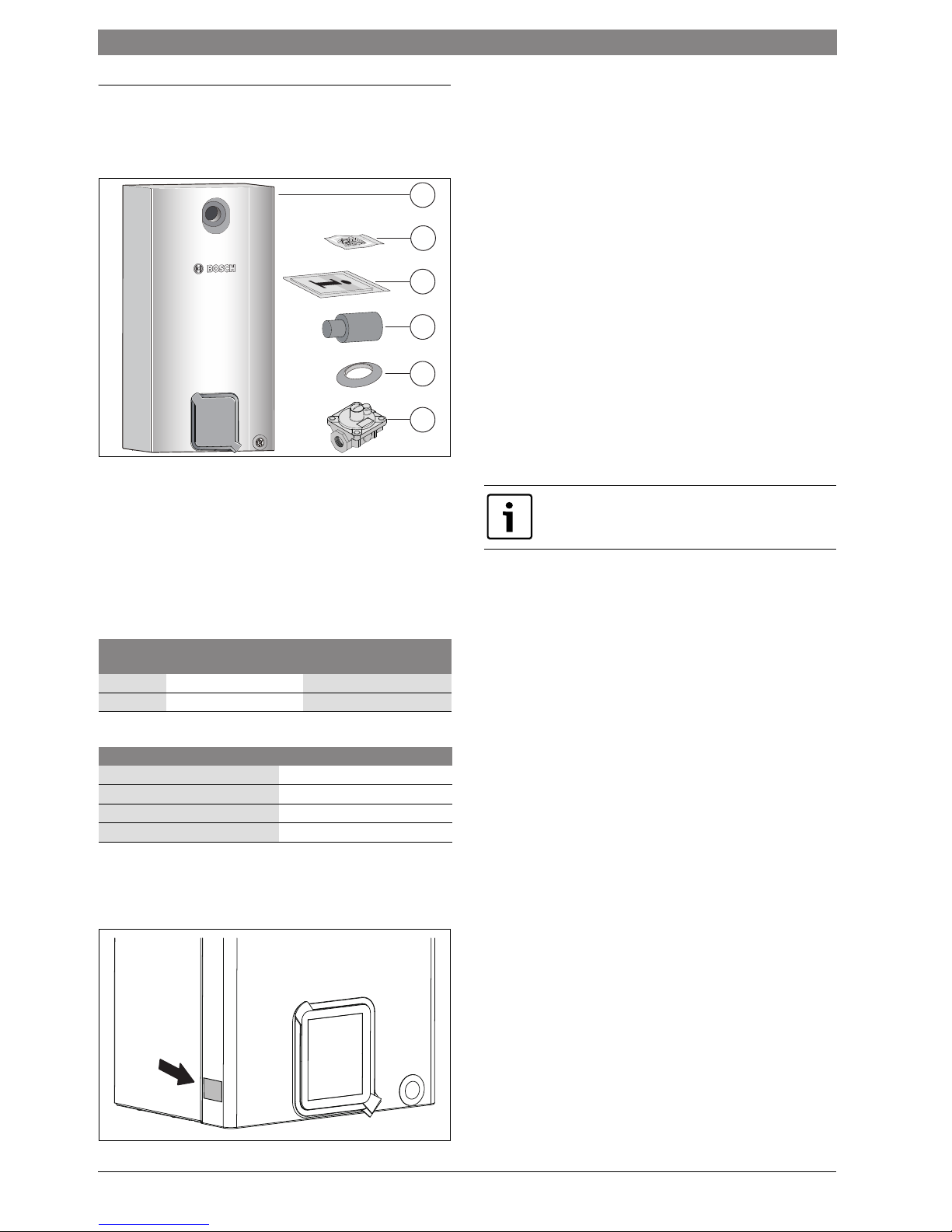
2.1 Standard delivery
Fig. 1
[1] Wall-mounted gas boiler
[2] Fixing material
[3] Set of printed documents for the appliance
[4] Flue pipe
[5] Grommet
[6] Regulator( Only for NG appliance )
2.2 Overview of the gas categories that can be used
The code number indicates the gas family according to AS 4552:
2.3 Data plate
Fig. 2
On the data plate, you will find details on the appliance output, approval
information and the series number.
2.4 Description of appliance
• Gas boiler only for external installation
• Gas boiler only for central heating
• Gas boiler for wall installation
• Power cable
• Liquid Crystal Display
• Automatic ignition
• Continuously controlled output
• Full backup via the electronics with flame monitoring and solenoid
valves according to EN 298
• Three-stage heating circuit pump with automatic air vent valve
• No minimum water circulation rate required
• Fixed connections for flue gas/combustion air as concentric pipe
Ø 60/100 mm
• Curve-controlled fan
• Temperature sensor and temperature control for central heating
• Temperature limiter in the flow
• Safety valve, pressure gauge, expansion vessel
2.5 Accessories
• Digital thermostat
Code
number
Wobbe index (WS)
(15 °C)
Gas type
23 12.2 - 55.0 MJ/m
3
NG
31 72.9 - 87.2 MJ/m
3
LPG
Table 2
LPG type1)
1) according to NZS 5435
Use
Commercial Propane recommended
Commercial Butane permitted
General Product permitted
Universal LPG (U-LPG) permitted
Table 3
1
3
4
5
6
2
8 716 473 216-01.2O
8 716 473 216-02.3O
Below is a list of typical accessories for this appliance.
You can find comprehensive details of all available
accessories in our catalogue.

Product details | 5
8 716 473 216 (2014/09)Gaz 6000 W
2.6 Dimensions and minimum clearances
Fig. 3
8 716 473 216-03.2O
898
Ø100
Ø60
R1/
2
440
67.75
400
112.75
132.75
320
300
139.5
75
R3/
4
R3/
4
R3/
4
≥ 100
≥ 100 ≥ 100
245
6 | Product details
Gaz 6000 W8 716 473 216 (2014/09)
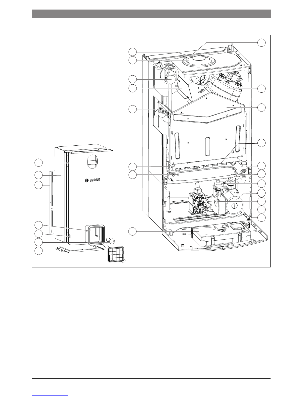
2.7 Appliance layout
Fig. 4
[1] Expansion vessel
[2] Fan
[3] Combustion chamber
[4] Burner pan with blast tube connection
[5] Ignition electrode
[6] Safety valve (heating circuit)
[7] Automatic air vent valve
[8] Heating circuit pump
[9] Pump speed selector switch
[10] Gas valve
[11] Pressure gauge
[12] Control device
[13] Monitoring electrode
[14] Flow temperature sensor
[15] Temperature limiter for heating block
[16] Air baffle
[17] Differential pressure switch
[18] Combustion air inlet
[19] Flue pipe
[20] Front cover for outer casing
[21] Main cover for outer casing
[22] Back plate for outer casing
[23] Interface cap
[24] Type plate
[25] Plastic cover
[26] Base plate for outer casing
8 716 473 216-04.4O
1
19
18
17
16
15
14
13
12
2
3
4
6
8
11
5
7
9
10
20
21
22
26
25
23
24
Product details | 7
8 716 473 216 (2014/09)Gaz 6000 W
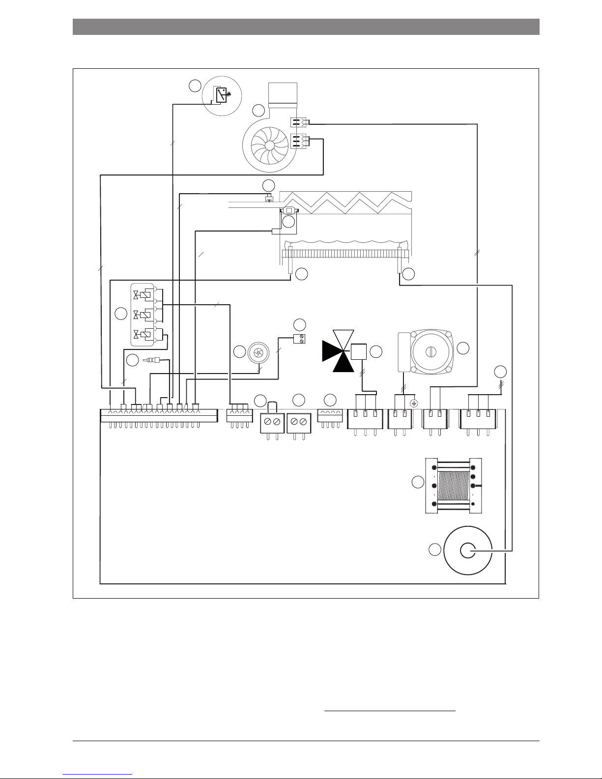
2.8 Electrical wiring diagram
Fig. 5
[1] Differential pressure switch
[2] Fan
[3] Flow temperature sensor
[4] Temperature limiter for heating block
[5] Monitoring electrode
[6] Ignition electrode
[7] Gas valve
[8] Cylinder temperature sensor connection (N.A)
[9] Turbine (N.A)
[10] 3-way valve (N.A)
[11] Heating circuit pump
[12] Hot water temperature sensor(N.A)
[13] 240 V power cable
[14] OTM connection or on/off controller
1)
[15] Connection for outside temperature sensor
[16] Diagnostic interface
[17] Transformer
[18] Ignition transformer
6 720 810 000-10.3O
13
2
11
15 16
14
7
4
2
3
2
2
2
2
9 10
8
3
5
6
4
1
18
17
12
3
M
TH EXT
DIAG
PUMP FAN N PE L a 3 WAY
GV
1) Remove jumper before connection

8 | Product details
Gaz 6000 W8 716 473 216 (2014/09)
2.9 Technical data
WBN 6000-30
Unit NG LPG
Max. rated heat output (P
max
) 80/60 °C kW 30 30
Max. rated heat input (Q
max
), central heating kW 33.2 33.2
Min. rated heat output (P
min
) 53/47 °C kW 99
Min. rated heat input (Q
min
), central heating kW 10.2 10.2
Gas supply rate
Natural gas type H (H
i(15 °C)
= 9.5 kWh/m3) MJ/hr 132.8 –
Butane/propane (Hi = 12.9 kWh/kg) MJ/hr – 132.8
Permissible gas supply pressure
NG Kpa 1.13 –
LPG Kpa – 2.75
Expansion vessel
Pre-charge pressure bar 0,5 0,5
Total capacity L 88
Calculation values for calculating cross-section to EN 13384
Flue gas temperature 80/60 °C max. rated °C 145 145
Flue gas temperature 80/60 °C min. rated °C 73 73
Flue gas mass flow rate, max. rated g/s 13.6 13.5
Flue gas mass flow rate, min. rated g/s 10,3 10,4
CO2 at max. rated output % 5.5 – 6.0 5.6 – 7.0
CO2 at min. rated output % 2.0 – 2.5 2.3 – 2.8
Flue gas rating group to G 636/G 635 G61/G
62
G61/G
62
NOx content mg/kWh 132 132
NOx class 33
Flue gas connection 60/100 60/100
General data
Power supply voltage AC ... V 240 240
Frequency Hz 50 50
Max. power consumption (central heating mode) W <130 <130
Standby power consumption W 22
Noise output level dB(A) 38 38
Max. flow temperature °C 40 – 82 40 – 82
Max. permissible operating pressure (PMS) heating bar 33
Permissible ambient temperature °C 0 – 50 0 – 50
Nominal capacity of appliance heating l 1,6 1,6
Weight (excl. packaging) kg 42 42
Dimensions, W x H x D mm 440 x 898x 315 440 x 898x 315
Table 4
Regulations | 9
8 716 473 216 (2014/09)Gaz 6000 W
3 Regulations
Where no specific instruction is given, reference should be made to the
following standards:
• AS/NZS 5601 Gas Installations,
• AS 1596 LPG storage and handling,
• AS 4552 Gas fired water heaters for hot water supply and/or central
heating,
• AS/NZS 3000 Electrical Installations,
• AS1697 Installation and maintenance of steel pipe systems for gas,
• AS 4032 Water supply - valves for the control of hot water supply
temperatures,
• AS 3498 Authorization requirements for plumbing products - water
heaters and hot-water storage tanks.
• AS 1910 Water supply - float control valves for use in hot and cold
water, AS 3500 National plumbing and drainage code.
4 Flue gas routing
Before fitting the gas boiler and the flue system, check with the local
planning authority and flue gas inspector whether there are any
restrictions.
The surface temperature at the combustion air pipe is below 85 °C for
concentric pipes. No minimum clearances to flammable building
materials are therefore required. Local regulations may differ from this
information and may stipulate minimum clearances to flammable
building materials.
4.1 Approved flue accessories
The flue accessories form part of the CE approval for the appliance. For
this reason, only the provided original flue accessories must be installed.
• Flue accessories, concentric pipe Ø 60/100 mm
4.2 Installation instructions
Fan stage :1 (Reference to service function 2.b.d ( page 21).
▶ Before fitting the flue kits:
Apply a thin coating of solvent-free grease (e.g. Vaseline) to the joint
seals.
▶ When fitting the balanced flue, always push the pipe fully home into
the sockets.
5 Installation
5.1 Important notes
▶ Before installing the appliance, consult your gas supply utility and
your local flue gas inspector [where appropriate].
Fill and top-up water for the heating system
Unsuitable fill and top-up water in the heating system can result in the
heat exchanger scaling up and failing prematurely.
Open vented heating systems
▶ Open vented heating systems must be converted to sealed systems.
Gravity fed heating systems
▶ Connect the appliance to the existing pipework via a low loss header
with a dirt separator.
Galvanised radiators and pipes
To prevent gas formation:
▶ Do not use galvanised radiators or pipes.
If a room thermostat is used
▶ Do not fit a thermostatic radiator valve to the radiator in the primary
room.
Anti-freeze
The following anti-freeze fluids are permitted:
Corrosion inhibitor
The following corrosion inhibitors are permissible:
Sealants
In our experience, adding sealants to the heating water may result in
problems (deposits in the heating block). We therefore advise against
using them.
Water circulation noises
To prevent water circulation noises:
▶ Fit an overflow valve or, with 2-pipe heating systems, a 3-way valve to
the radiator furthest from the boiler.
CAUTION: Low efficiency and functional problems if an
incorrect fan stage is used!
DANGER: Risk of explosion!
▶ Turn off gas valve before working on gas-carrying
components.
▶ Check for leaks before working on gas-carrying
components.
Installation, power connection, connection on the gas
and flue gas side and commissioning must only be
carried out by a contractor approved for such work by
the local gas or power supply authority.
Not suitable for pool or spa pool application.
Hardness range Water treatment
soft ( 8.4 °dH) not required
medium (8.4 - 14 °dH) recommended
hard (14 °dH) required
Table 5
For straightforward water treatment:
▶ Use the system approved by us.
Designation Concentration
Varidos FSK 22 - 55 %
Alphi - 11 25 - 40 %
Glythermin NF 20 - 62 %
Antifrogen N 20 - 40 %
Table 6
Designation Concentration
Fernox see supplier information
Sentinel see supplier information
Table 7
10 | Installation
Gaz 6000 W8 716 473 216 (2014/09)
Mono-lever taps and thermostatic mixer taps
All mono-lever taps and thermostatic mixer taps can be used.
LPG
To protect the appliance against excessive pressure:
▶ Fit a pressure regulator with a safety valve.
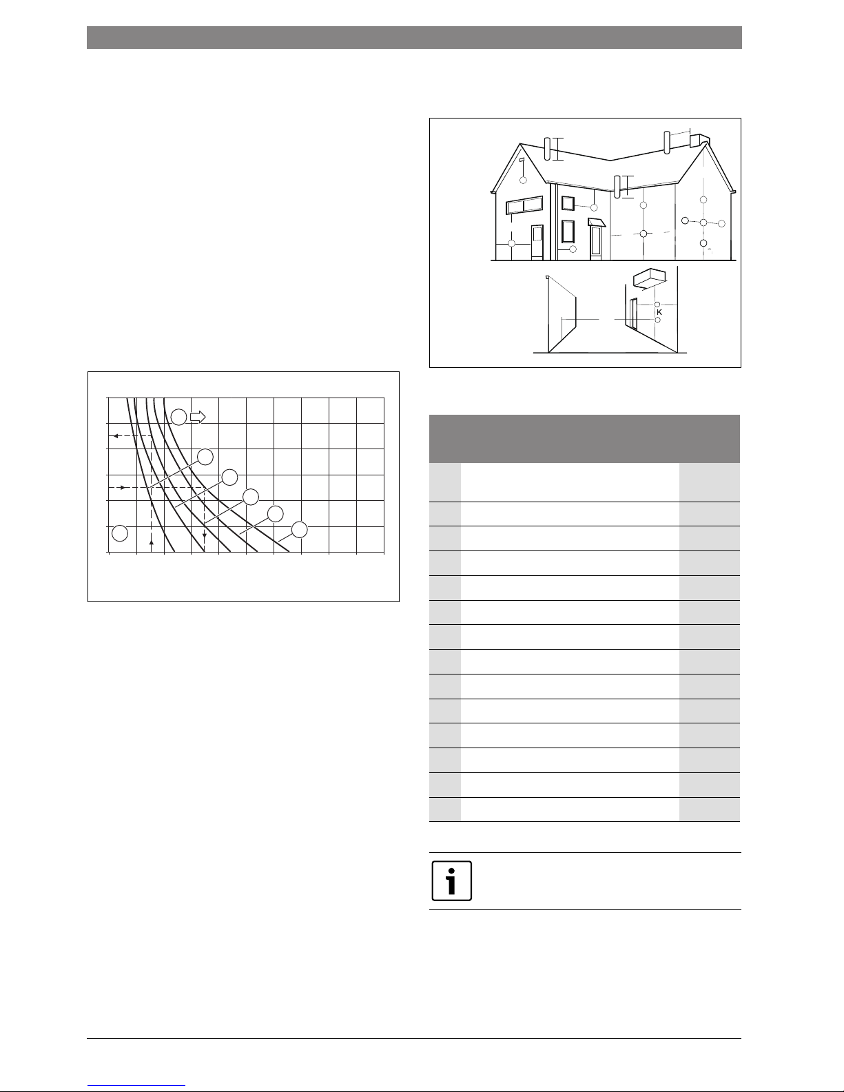
5.2 Checking the size of the expansion vessel
The following diagram provides you with a rough estimate of whether the
installed expansion vessel is sufficient or whether an additional
expansion vessel is required.
The characteristic curves shown are based on the following key data:
• 1% water volume in expansion vessel or 20% of nominal volume of
expansion vessel
• Differential operating pressure of the safety valve of 0.5 bar,
according to DIN 3320
• Pre-charge pressure of expansion vessels matches static head of the
system above the heat exchanger
• Maximum operating pressure of 3 bar
Fig. 6
I Pre-charge pressure 0.2 bar
II Pre-charge pressure 0.5 bar (default setting)
III Pre-charge pressure 0.75 bar
IV Pre-charge pressure 1.0 bar
V Pre-charge pressure 1.2 bar
t
V
Flow temperature
V
A
System content in litres
A Operating range of the expansion vessel
B Additional expansion vessel required
▶ If intersection is on the limit: determine the exact size of the vessel
according to DIN EN 12828.
▶ If the intersection is to the right of the curve: install additional
expansion vessel.
5.3 Siting the appliance
Regulations concerning the installation site
Fig. 7
Key to illustration
450 500350 400250200 300150100500
30
90
70
80
60
50
40
6 720 610 421-07.2O
T/°C
VA/l
B
A
IV
III
II
I
V
Fan assisted flue terminal position
Terminal Position
Minimum
Spacing
A Directly below, an opening window, air vent or
other ventilation opening
1000mm
B Below guttering, drain pipes or soil pipes 75mm
C Below eaves 300mm
D Below balconies or a car port roof* 300mm
E From vertical drain pipes or soil pipes 75mm
F From internal or external corners 300mm
G Above adjacent ground, roof or balcony level 300mm
H From a surface facing the terminal 1500mm
I From a terminal facing the terminal 1200mm
K Vertically from a terminal on the same wall 1500mm
L Horizontally from a terminal on the wall 300mm
M Adjacent to opening 300mm
N Above intersection with roof 500mm
O For a vertical structure on the roof
500mm
Table 8
Installations in car ports are not recommended.
8 716 473 216-20.1O
Flue terminal positions
for boilers in accordance
with AS5601
A
F
M
G
M
B,C
F
B,C
K
G
C
L
A
N
N
O
E
J
K
D
F
K
G
G
G
H, I
K
L
Installation | 11
8 716 473 216 (2014/09)Gaz 6000 W
▶ Pluming will occur at the terminal so terminal positions where this
could cause a nuisance should be avoided.
▶ The air supply and the flue gas exhaust must meet the applicable
general regulations. Please consult the instructions provided with the
flue terminal kits prior to installation.
▶ The boiler must be installed so that the terminal is exposed to the
external air.
▶ It is important that the position of the terminal allows the free passage
of air at all times.
▶ Minimum acceptable spacing from the openings are specified above,
for domestic situations in accordance with AS 5601.
Combustion air
In order to prevent corrosion, the combustion air must not contain any
corrosive substances.
Substances classed as corrosion-promoting include halogenated
hydrocarbons which contain chlorine and fluorine compounds. They
may be found in solvents, paints, adhesives, aerosol propellants and
household cleaners, for example..
Surface temperature
The maximum surface temperature of the appliance is below 85 °C. That
means that no special safety precautions are required with regard to
flammable building materials and fitted furniture. If regulations differ in
individual countries they must be observed.
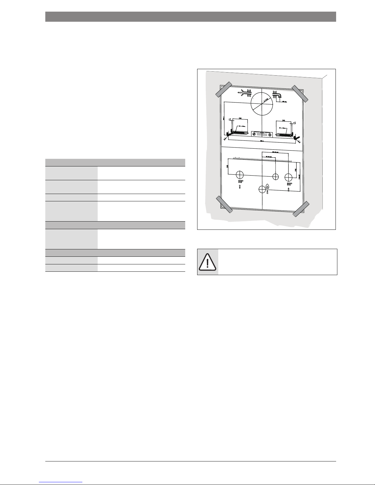
5.4 Fitting the appliance
▶ Fix the mounting template supplied with the documents to the wall,
observing a lateral clearance of at least 100 mm ( page 5).
▶ Drill the holes for the screw hooks according to the mounting
template.
Fig. 8 Mounting template
▶ Remove the mounting template.
▶ Remove packing, taking care to observe the instructions on the
packing.
▶ Check the destination country on the type plate and make sure that
the gas type specified on the identification plate matches that of the
gas supplied by the gas utility company ( page 6).
Industrial sources
Chemical cleaners Trichloroethylene, tetrachloroethylene,
fluorinated hydrocarbons
Degreasing baths Perchloroethylene, trichloroethylene,
methylchloroform
Printing shops Trichloroethylene
Hairdressing salons Aerosol propellants, hydrocarbons
containing fluorine and chlorine
(difluorodichloromethane)
Household sources
Cleaning and degreasing
agents
Perchloroethylene, methylchloroform,
trichloroethylene, methylene chloride,
carbon tetrachloride, hydrochloric acid
Hobby rooms
Solvents and thinners Various chlorinated hydrocarbons
Aerosols Chlorofluorinated hydrocarbons (Freon)
Table 9 Corrosive materials
NOTICE: Residues in the pipework can damage the
appliance.
▶ Flush out the system to remove all dirt residues.
8 716 473 216-06.1O
 Loading...