

Bosch VEZ IP Installation Manual
AutoDome Easy IP
VEZ IP Series
en Installation Manual


AutoDome Easy IP
Table of Contents | en iii
Table of Contents
1Safety 1
1.1 Important Safety Instructions 1
1.2 Safety Precautions 4
1.3 Important Notices 4
1.4 Customer Support and Service 11
2 Unpacking 13
2.1 Parts List 13
2.2 Additional Tools Required 13
2.3 Safety Rules 14
3Description 15
4 Preparing the Wiring 17
4.1 Ethernet (control and video) 17
4.2 Power 17
4.3 Alarm 18
5 Connections 19
5.1 Connecting to the Ethernet 19
5.2 Connecting the Power 19
5.3 Connecting the Alarm Input 20
6 Mounting Installation 21
6.1 Installing the Wall Mount 21
6.2 Installing the Pipe Mount 25
6.2.1 Installing the Base to a Metal Junction Box 30
6.2.2 Powering On 31
7 Setting Protocol and Video Format 33
Bosch Security Systems, Inc. Installation Manual F01U079609 | 1.0 | 2008.08

iv en | Table of Contents
AutoDome Easy IP
8 Configuring IP Communications 35
8.1 Overview of Features 35
8.2 System Requirements 37
8.3 IP Network Address Requirements 38
8.4 Connecting the AutoDome Easy IP to the PC 38
8.5 Installing the Required Software 39
8.6 Changing the Network Settings/IP Address 40
8.6.1 Installing the Configuration Manager 40
8.6.2 Using the Configuration Tool 41
8.6.3 Using the AutoDome Easy IP Web Server 41
9 Viewing Live Images and Controlling the PTZ 45
9.1 Establishing a Connection 45
9.2 Configuring Data Streams 45
9.3 Controlling Camera Operations 46
9.4 Entering a Keyboard Control Command 49
10 Navigating the Menus 53
10.1 Preset Menu 54
10.1.1 Setting and Saving Presets 55
10.1.2 Recalling a Preset Position 56
10.1.3 Creating Titles 56
10.2 Tour Menu 57
10.2.1 Setting a Tour 58
10.2.2 Running / Stopping a Tour 59
10.3 Auto Pan Menu 59
10.3.1 Setting Auto Pans 60
10.3.2 Run Auto Pan 62
10.4 Sector Menu 62
10.5 Alarm Menu 64
10.5.1 Configuring the Alarm for IP Alarm Features 65
10.5.2 Releasing an Alarm 66
10.6 Camera Setup Menu 66
10.6.1 Focus Control Menu 67
10.6.2 WB Control Menu 69
10.6.3 AE Control Menu 71
F01U079609 | 1.0 | 2008.08 Installation Manual Bosch Security Systems, Inc.

AutoDome Easy IP
Table of Contents | en v
10.6.4 L/L Control Menu 73
10.7 Picture Menu 74
10.7.1 Initialize Camera Menu 75
10.8 Dome Setup Menu 75
10.8.1 Setting the Language 77
10.9 Inactivity Function 78
10.10 Initialize Dome Menu 80
10.10.1 Dome Information Menu 80
11 Recording Menus 81
11.1 Selecting Recordings 81
11.1.1 Controlling Playback 82
11.1.2 Printing a Screenshot 83
12 Settings Menus 85
12.1 General Main Menu 85
12.1.1 Identification Menu 86
12.1.2 Display Stamping Menu 86
12.1.3 Password Menu 88
12.1.4 Language Menu 89
12.1.5 Date/Time Menu 89
12.1.6 Time Server Menu 90
12.2 Encoder Main Menu 93
12.2.1 Picture Settings Menu 94
12.2.2 Encoder Profile Menu 94
12.2.3 Profile Configuration 95
12.2.4 JPEG Posting Menu 98
12.3 Recording Main Menu 100
12.4 Storage Medium Menu 100
12.5 iSCSI Menu 101
12.6 Partitioning 105
12.6.1 Viewing the Partition Status 111
12.6.2 Creating A Partition 112
12.6.3 Editing a Partition 112
12.6.4 Deleting Recordings 114
12.6.5 Deleting all Partitions 114
Bosch Security Systems, Inc. Installation Manual F01U079609 | 1.0 | 2008.08

vi en | Table of Contents
AutoDome Easy IP
12.7 Recording Profiles 115
12.8 Recording Scheduler 116
12.8.1 Holidays 118
12.8.2 Deleting Holidays 118
12.8.3 Time Periods 119
12.8.4 Activating the Recording 119
12.8.5 Recording Status 119
12.9 Alarm Menu 119
12.9.1 Alarm Sources 120
12.9.2 Alarm Connections 120
12.9.3 Sending an Alarm E-mail 122
12.10 Service Main Menu 123
12.10.1 Network Menu 123
12.10.2 Multicasting 125
12.10.3 Encryption 126
12.10.4 Version Information 128
12.10.5 Livepage Configuration 128
12.10.6 Licenses 130
12.10.7 Maintenance 130
13 Keyboard Commands by Number 133
14 Preventive Maintenance 135
14.1 Spare Parts List 135
15 Troubleshooting 137
F01U079609 | 1.0 | 2008.08 Installation Manual Bosch Security Systems, Inc.

AutoDome Easy IP Safety | en 1
1Safety
1.1 Important Safety Instructions
Read, follow, and retain for future reference all of the following
safety instructions. Heed all warnings on the unit and in the
operating instructions before operating the unit.
1. Cleaning - Unplug the unit from the outlet before cleaning.
Follow any instructions provided with the unit. It is
generally sufficient to use a dry cloth for cleaning, but a
moist lint-free cloth or leather shammy may also be used.
Do not use liquid cleaners or aerosol cleaners.
2. Heat sources - Do not install the unit near any heat
sources such as radiators, heaters, stoves, or other devices
(including amplifiers) that produce heat.
3. Ventilation - Any openings in the unit housing are provided
for ventilation to prevent overheating and ensure reliable
operation. Do not block or cover these openings. Do not
place the unit in an enclosure unless proper ventilation is
provided, or the manufacturer's instructions have been
adhered to.
4. Water - Do not use this unit near water, for example near a
bathtub, washbowl, sink, laundry basket, in a damp or wet
basement, near a swimming pool, in an outdoor
installation, or in any area classified as a wet location. To
reduce the risk of fire or electrical shock, do not expose
this unit to rain or moisture.
5. Object and liquid entry - Never push objects of any kind
into this unit through openings, as they may touch
dangerous voltage points or short out parts, which could
result in a fire or electrical shock. Never spill liquid of any
kind on the unit. Do not place objects filled with liquids,
such as vases or cups, on the unit.
6. Lightning - For added protection during a lightning storm,
or when leaving this unit unattended and unused for long
periods, unplug the unit from the wall outlet and
disconnect the cable system. This will prevent damage to
Bosch Security Systems, Inc. Installation Manual F01U079609 | 1.0 | 2008.08

2 en | Safety AutoDome Easy IP
the unit from lightning and power line surges.
7. Control adjustment - Adjust only those controls specified
in the operating instructions. Improper adjustment of
other controls may cause damage to the unit. Use of
controls or adjustments, or performance of procedures
other than those specified, may result in hazardous
radiation exposure.
8. Overloading - Do not overload outlets and extension cords.
This can cause fire or electrical shock.
9. Power cord and plug protection - Protect the plug and
power cord from foot traffic and from being pinched by
items placed upon or against them at electrical outlets;
also protect the power cord's exit from the unit. For units
intended to operate with 230 VAC, 50 Hz, the input and
output power cord must comply with the latest versions of
IEC Publication 227 or IEC Publication 245.
10. Power disconnect - Units with or without ON/OFF
switches have power supplied whenever the power cord is
inserted into the power source; however, the unit is
operational only when the ON/OFF switch is in the ON
position. The power cord is the main power disconnect
device for switching off the voltage for all units.
11. Power sources - Operate the unit only via the type of
power source indicated on the label. Before proceeding,
be sure to disconnect the power from the cable being
connected to the unit.
– For battery powered units, refer to the operating
instructions.
– For units supplied by an external power source, use
only the recommended or approved power supplies.
–For limited power source units, this power source
must comply with EN60950. Substitutions may
damage the unit or cause fire or shock.
– For 24 VAC units, voltage applied to the unit's power
input should not exceed ±10% or 26.4 VAC. Usersupplied wiring must comply with local electrical
codes (Class 2 power levels). Do not ground the
F01U079609 | 1.0 | 2008.08 Installation Manual Bosch Security Systems, Inc.

AutoDome Easy IP Safety | en 3
supply at the terminals or at the unit's power supply
terminals.
– If unsure of the type of power supply to use, contact
your dealer or local power company.
12. Servicing - Do not attempt to service this unit yourself.
Opening or removing covers may expose you to dangerous
voltage or other hazards. Refer all servicing to qualified
service personnel.
13. Damage requiring service - Unplug the unit from the main
AC power source and refer servicing to qualified service
personnel when any damage to the equipment has
occurred, for example if:
– the power supply cord or plug is damaged
– exposure to moisture, water, and/or inclement
weather (rain, snow etc.)
– liquid has been spilled in or on the equipment
– an object has fallen into the unit
– the unit has been dropped or the unit cabinet is
damaged
– the unit exhibits a distinct change in performance
– the unit does not operate normally when the user
correctly follows the operating instructions.
14. Replacement parts - Be sure the service technician uses
replacement parts specified by the manufacturer, or that
they have the same characteristics as the original parts.
Unauthorized substitutions may cause fire, electrical
shock, or other hazards.
15. Safety check - Safety checks should be performed on
completion of service or repairs to the unit, to ensure that
the unit is in proper operating condition.
16. Installation - Install in accordance with the manufacturer's
instructions and in accordance with applicable local codes.
17. Attachments, changes, or modifications - Only use
attachments/accessories specified by the manufacturer.
Any change to or modification of the equipment not
expressly approved by Bosch could void the warranty or, in
Bosch Security Systems, Inc. Installation Manual F01U079609 | 1.0 | 2008.08
4 en | Safety AutoDome Easy IP
the case of an authorization agreement, authority to
operate the equipment.
1.2 Safety Precautions
DANGER! DANGER! High risk:
This symbol indicates an imminently hazardous situation such
as "Dangerous Voltage" inside the product. If not avoided, this
will result in an electrical shock, serious bodily injury, or death.
WARNING! WARNING! Medium risk:
Indicates a potentially hazardous situation. If not avoided, this
!
may result in minor or moderate injury. Alerts the user to
important instructions accompanying the unit.
CAUTION! CAUTION! Low risk: (without safety alert symbol)
Indicates a potentially hazardous situation. If not avoided, this
may result in damage to property or risk of damage to the unit.
NOTICE! NOTICE! This symbol indicates information or a
company policy that relates directly or indirectly to the safety of
i
personnel or protection of property.
1.3 Important Notices
Accessories - Do not place this unit on an unstable stand,
tripod, bracket, or mount. The unit may fall, causing serious
injury to persons and/or severe damage to the unit. Use only
with the cart, stand, tripod, bracket, or table specified by the
manufacturer. When a cart is used, exercise caution and care
when moving the cart/apparatus combination to avoid tipping it
over, which could result in injury. Quick stops, excessive force,
or uneven surfaces may cause the cart/unit combination to
overturn. Mount the unit in line with the manufacturer's
instructions.
All-pole power switch - Incorporate an all-pole power switch,
with a contact separation of at least 3 mm in each pole, into the
electrical installation of the building. If it is needed to open the
housing for servicing and/or other activities, use this all-pole
F01U079609 | 1.0 | 2008.08 Installation Manual Bosch Security Systems, Inc.

AutoDome Easy IP Safety | en 5
switch as the main disconnect device for switching off the
voltage to the unit.
Camera grounding - When mounting the camera in potentially
damp environments, ensure the system is grounded through
the metal housing of the unit (see section: Connecting the
Power).
Camera lens - A camera lens fitted in the indoor housing must
comply with and be tested in accordance with UL/IEC60950.
Any output or signal lines from the camera must be SELV or
Limited Power Source. For safety reasons, the environmental
specification of the camera lens assembly must be within the
environmental specification of -10 °C (14 °F) to 40 °C (104 °F).
Camera signal - Protect the cable with a primary protector if
the camera signal is over 140 feet, in accordance with NEC800
(CEC Section 60).
Coax grounding:
– Ground the cable system if connecting an outside cable
system to the unit.
– Connect outdoor equipment to the unit's inputs only after
this unit has had its grounding plug connected to a
grounded outlet or its ground terminal is properly
connected to a ground source.
– Disconnect the unit's input connectors from outdoor
equipment before disconnecting the grounding plug or
grounding terminal.
– Follow proper safety precautions, such as grounding, for
any outdoor device connected to this unit.
U.S.A. models only - Section 810 of the National Electrical Code,
ANSI/NFPA No. 70, provides information regarding proper
grounding of the mount and supporting structure, grounding of
the coax to a discharge unit, size of grounding conductors,
location of discharge unit, connection to grounding electrodes,
and requirements for the grounding electrode.
NOTICE! This device is intended for use in public areas only.
U.S. federal law strictly prohibits surreptitious recording of oral
i
communications.
Bosch Security Systems, Inc. Installation Manual F01U079609 | 1.0 | 2008.08
6 en | Safety AutoDome Easy IP
Your Bosch product was developed and manufactured with
high-quality material and components that can be recycled and
reused. This symbol means that electronic and electrical
appliances that have reached the end of their service life must
be collected and disposed of separately from household waste
material. Separate collecting systems are usually in place for
disused electronic and electrical products. Please dispose of
these units at an environmentally compatible recycling facility,
in line with European Directive 2002/96/EC.
Environmental statement - Bosch has a strong commitment to
the environment. This unit has been designed to respect the
environment as much as possible.
Electrostatic-sensitive device - Take proper CMOS/MOS-FET
handling precautions to avoid electrostatic discharge.
NOTE: You must wear grounded wrist straps and observe
proper ESD safety precautions when handling the electrostaticsensitive printed circuit boards.
Fuse rating - For security protection of the device, the branch
circuit protection must be secured with a maximum fuse rating
of 16 A. This must be in accordance with NEC800 (CEC Section
60).
Grounding and polarization - This unit may be fitted with a
polarized alternating current line plug (a plug with one blade
wider than the other blade). This safety feature allows the plug
to fit into the power outlet in only one way. If unable to insert
the plug fully into the outlet, contact a locally certified
electrician to replace the obsolete outlet. Do not defeat the
safety purpose of the polarized plug.
Alternatively, this unit may be fitted with a 3-pole grounding
plug (a plug with a third pin for earth grounding). This safety
feature allows the plug to fit into a grounded power outlet only.
If unable to insert the plug into the outlet, contact a locally
certified electrician to replace the obsolete outlet. Do not
defeat the safety purpose of the grounding plug.
F01U079609 | 1.0 | 2008.08 Installation Manual Bosch Security Systems, Inc.

AutoDome Easy IP Safety | en 7
Moving - Disconnect the power before moving the unit. Move
the unit with care. Excessive force or shock may damage the
unit and the hard disk drives.
Permanently connected equipment - Incorporate a readily
accessible disconnect device in the building installation wiring.
Pluggable equipment - Install the socket outlet near the
equipment so it is easily accessible.
Power disconnect - Units have power supplied whenever the
power cord is inserted into the power source. The power cord
is the main power disconnect for all units.
Power lines - Do not locate the camera near overhead power
lines, power circuits, electrical lights, or anywhere where it
might come into contact with power lines, circuits, or lights.
SELV
All the input/output ports are Safety Extra Low Voltage (SELV)
circuits. SELV circuits should only be connected to other SELV
circuits.
Because the ISDN circuits are treated like telephone-network
voltage, avoid connecting the SELV circuit to the Telephone
Network Voltage (TNV) circuits.
Video loss - Video loss is inherent to digital video recording;
therefore, Bosch Security Systems cannot be held liable for any
damage that results from missing video information. To
minimize the risk of lost digital information, Bosch Security
Systems recommends multiple, redundant recording systems,
and a procedure to back up all analog and digital information.
NOTICE! This is a class A product. In a domestic environment
this product may cause radio interference, in which case the
i
user may be required to take adequate measures.
FCC & ICES INFORMATION
(U.S.A. and Canadian Models Only)
Bosch Security Systems, Inc. Installation Manual F01U079609 | 1.0 | 2008.08

8 en | Safety AutoDome Easy IP
This device complies with part 15 of the FCC Rules. Operation is
subject to the following conditions:
– this device may not cause harmful interference, and
– this device must accept any interference received,
including interference that may cause undesired operation.
Note
This equipment has been tested and found to comply with the
limits for a Class A digital device, pursuant to Part 15 of the
FCC Rules and ICES-003 of Industry Canada. These limits are
designed to provide reasonable protection against harmful
interference when the equipment is operated in a commercial
environment. This equipment generates, uses, and radiates
radio frequency energy and, if not installed and used in
accordance with the instruction manual, may cause harmful
interference to radio communications. Operation of this
equipment in a residential area is likely to cause harmful
interference, in which case the user will be required to correct
the interference at his expense.
Intentional or unintentional modifications not expressly
approved by the party responsible for compliance shall not be
made. Any such modifications could void the user's authority to
operate the equipment. If necessary, the user should consult
the dealer or an experienced radio/television technician for
corrective action.
The user may find the following booklet, prepared by the
Federal Communications Commission, helpful: How to Identify
and Resolve Radio-TV Interference Problems. This booklet is
available from the U.S. Government Printing Office,
Washington, DC 20402, Stock No. 004-000-00345-4.
INFORMATIONS FCC ET ICES
(modèles utilisés aux États-Unis et au Canada uniquement)
Ce produit est conforme aux normes FCC partie 15. La mise en
service est soumises aux deux conditions suivantes:
– cet appareil ne peut pas provoquer d'interférence nuisible
F01U079609 | 1.0 | 2008.08 Installation Manual Bosch Security Systems, Inc.
et

AutoDome Easy IP Safety | en 9
– cet appareil doit pouvoir tolérer toutes les interférences
auxquelles il est soumit, y compris les interférences qui
pourraient influer sur son bon fonctionnement.
AVERTISSEMENT: Suite à différents tests, cet appareil s’est
révélé conforme aux exigences imposées aux appareils
numériques de Classe A en vertu de la section 15 du règlement
de la Commission fédérale des communications des États-Unis
(FCC). Ces contraintes sont destinées à fournir une protection
raisonnable contre les interférences nuisibles quand l'appareil
est utilisé dans une installation commerciale. Cette appareil
génère, utilise et émet de l'energie de fréquence radio, et peut,
en cas d'installation ou d'utilisation non conforme aux
instructions, générer des interférences nuisibles aux
communications radio. L’utilisation de ce produit dans une
zone résidentielle peut provoquer des interférences nuisibles.
Le cas échéant, l’utilisateur devra remédier à ces interférences
à ses propres frais.
Au besoin, l’utilisateur consultera son revendeur ou un
technicien qualifié en radio/télévision, qui procédera à une
opération corrective. La brochure suivante, publiée par la
Commission fédérale des communications (FCC), peut s’avérer
utile : « How to Identify and Resolve Radio-TV Interference
Problems » (Comment identifier et résoudre les problèmes
d’interférences de radio et de télévision). Cette brochure est
disponible auprès du U.S. Government Printing Office,
Washington, DC 20402, États-Unis, sous la référence n° 004000-00345-4.
AVERTISSEMENT: Ce produit est un appareil de Classe A. Son
utilisation dans une zone résidentielle risque de provoquer des
interférences. Le cas échéant, l’utilisateur devra prendre les
mesures nécessaires pour y remédier.
Disclaimer
Underwriter Laboratories Inc. ("UL") has not tested the
performance or reliability of the security or signaling aspects of
this product. UL has only tested fire, shock and/or casualty
hazards as outlined in UL's Standard(s) for Safety for Closed
Bosch Security Systems, Inc. Installation Manual F01U079609 | 1.0 | 2008.08

10 en | Safety AutoDome Easy IP
Circuit Television Equipment, UL 2044. UL Certification does not
cover the performance or reliability of the security or signaling
aspects of this product.
UL MAKES NO REPRESENTATIONS, WARRANTIES, OR
CERTIFICATIONS WHATSOEVER REGARDING THE
PERFORMANCE OR RELIABILITY OF ANY SECURITY OR
SIGNALING-RELATED FUNCTIONS OF THIS PRODUCT.
Copyright
This user guide is the intellectual property of Bosch Security
Systems, Inc. and is protected by copyright.
All rights reserved.
Trademarks
All hardware and software product names used in this
document are likely to be registered trademarks and must be
treated accordingly.
NOTICE! This user guide has been compiled with great care and
the information it contains has been thoroughly verified. The
text was complete and correct at the time of printing. The
ongoing development of the products may mean that the
content of the user guide can change without notice. Bosch
i
Security Systems accepts no liability for damage resulting
directly or indirectly from faults, incompleteness or
discrepancies between the user guide and the product
described.
F01U079609 | 1.0 | 2008.08 Installation Manual Bosch Security Systems, Inc.

AutoDome Easy IP Safety | en 11
1.4 Customer Support and Service
If this unit needs service, contact the nearest Bosch Security
Systems Service Center for authorization to return and shipping
instructions.
Service Centers
USA
Telephone: 800-366-2283 or 585-340-4162
Fax: 800-366-1329
E-mail: cctv.repair@us.bosch.com
Customer Service
Telephone: 888-289-0096
Fax: 585-223-9180
E-mail: security.sales@us.bosch.com
Technical Support
Telephone: 800-326-1450
Fax: 585-223-3508 or 717-735-6560
E-mail: technical.support@us.bosch.com
Repair Center
Telephone: 585-421-4220
Fax: 585-223-9180 or 717-735-6561
E-mail: security.repair@us.bosch.com
Canada
Telephone: 514-738-2434
Fax: 514-738-8480
Europe, Middle East & Asia Pacific Region
Telephone: 44 (0) 1495 274558
Fax: 44 (0) 1495 274280
E-mail: rmahelpdesk@solectron.com
More information
For additional information, please contact your Bosch Security
Systems representative or visit our website at
www.boschsecurity.com
Bosch Security Systems, Inc. Installation Manual F01U079609 | 1.0 | 2008.08

12 en | Safety AutoDome Easy IP
F01U079609 | 1.0 | 2008.08 Installation Manual Bosch Security Systems, Inc.

AutoDome Easy IP Unpacking | en 13
2 Unpacking
This equipment should be unpacked and handled with care. If
an item appears to have been damaged in shipment, notify the
shipper immediately.
– Remove the blue round packing foam between the PTZ and
the bubble.
– Remove the clear protective plastic sheet on top of the
bubble.
– Verify that all the parts listed in Section 2.1 Parts List,
page 13 are included. If any items are missing, notify your
Bosch Security Systems Sales or Customer Service
Representative.
– The original packing carton is the safest container in which
to transport the unit and must be used if returning the unit
for service. Save it for possible future use.
2.1 Parts List
The AutoDome Easy IP includes the following components:
– One (1) PTZ Dome (dome camera)
– One (1) accessory kit including
– One (1) locking torx wrench (T-10)
– One (1) locking torx wrench (T-20)
– Four (4) tapping screws
– Four (4) plastic anchors
– One (1) mounting bracket (mounted to bottom of
dome)
– One (1) power connector (red connector with red and
orange wires)
– One (1) alarm connector (blue connector with blue and
purple wires)
– One (1) Installation and Configuration manual
2.2 Additional Tools Required
– No. 2 Phillips screwdriver
Bosch Security Systems, Inc. Installation Manual F01U079609 | 1.0 | 2008.08

14 en | Unpacking AutoDome Easy IP
2.3 Safety Rules
To ensure safety, the following warnings are specified:
– The device must be installed and maintained by skilled
technical personnel.
– Connect the device to a power source corresponding to
the indications given on the marking label.
– Use only the attachments/accessories specified by the
manufacturer.
– Unplug the device during lightning storms or when unused
for long periods of time.
– Do not use the device near water.
– Do not use the device in the presence of inflammable
substances.
– Do not allow children or unauthorized personnel to use the
device.
– Do not block any ventilation openings.
– Keep this manual for future reference.
F01U079609 | 1.0 | 2008.08 Installation Manual Bosch Security Systems, Inc.

AutoDome Easy IP Unpacking | en 15
Bosch Security Systems, Inc. Installation Manual F01U079609 | 1.0 | 2008.08
16 en | Description AutoDome Easy IP
3Description
The AutoDome Easy IP web interface, on-screen keyboard
controller, and camera make up the building blocks for this
surveillance/security system. By using multiple on-screen
keyboard controllers and multiple dome cameras, no place is
too large for monitoring. Extensible and flexible architecture
facilitates remote control functions via a web browser or DVR
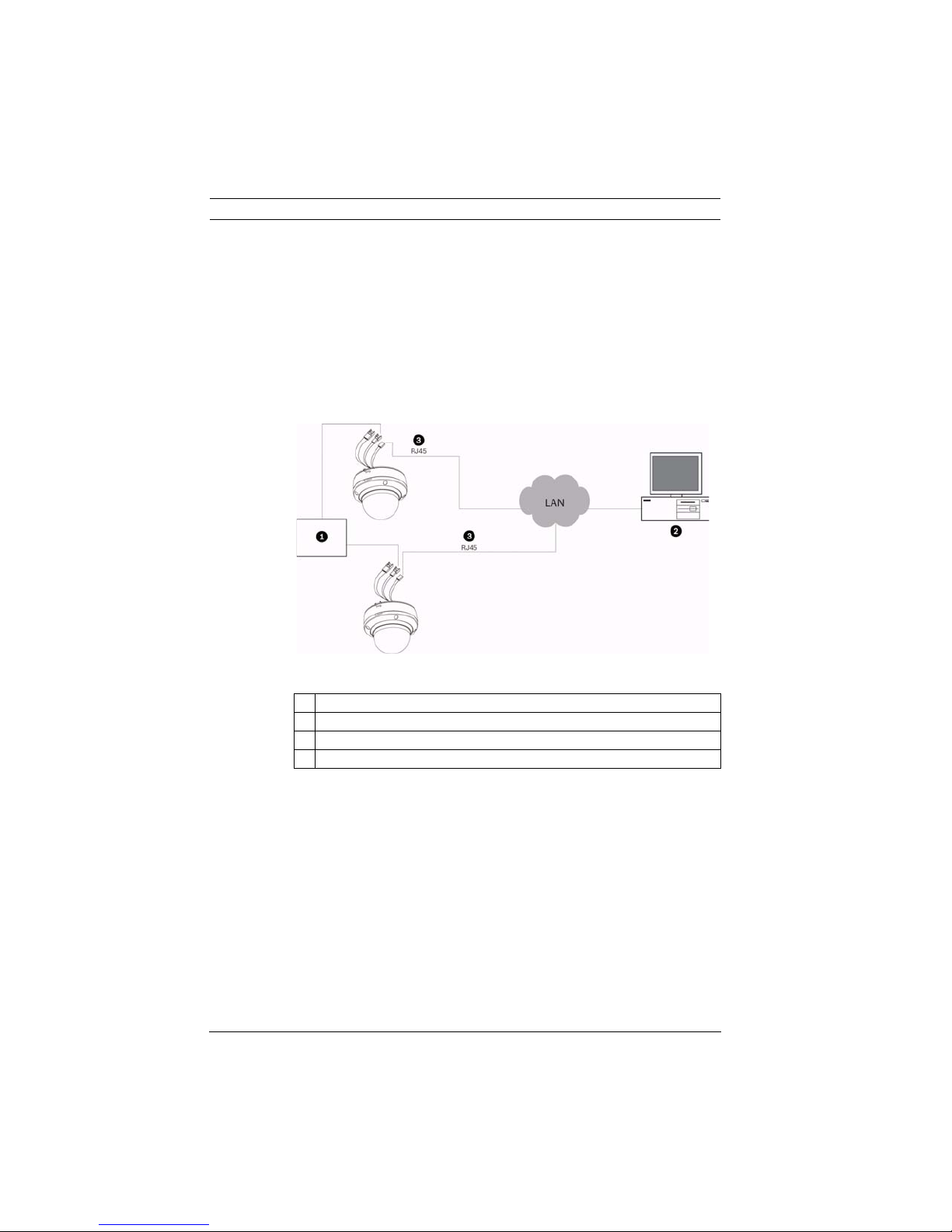
(see Figure 3.1 for a sample configuration).
Figure 3.1 System configuration
Description
1Power supply
2PC
3 Ethernet over CAT 5E or CAT 6 cable
F01U079609 | 1.0 | 2008.08 Installation Manual Bosch Security Systems, Inc.

AutoDome Easy IP Description | en 17
Bosch Security Systems, Inc. Installation Manual F01U079609 | 1.0 | 2008.08
18 en | Preparing the Wiring AutoDome Easy IP
4 Preparing the Wiring
There are three (3) types of wires required: ethernet, power,
and alarm. Each section provides the specifications for the
recommended wire.
CAUTION! Installation should only be performed by qualified
service personnel in accordance with the National Electrical
!
Code or applicable local codes.
4.1 Ethernet (Control and Video)
The AutoDome Easy IP is connected to a 10 Base-T/100 Base-TX
network either directly or via a hub. Both video and control are
transmitted over a standard IP network using the built-in web
server.
Cable type CAT-5E or CAT 6 Ethernet
Maximum distance 100 m (328 ft)
Bandwidth 10 Base-T/100 Base-TX
Terminal connector RJ45
Ethernet connections
The AutoDome Easy IP contains a CAT-5E Ethernet cable
terminated with an RJ45 female connector.
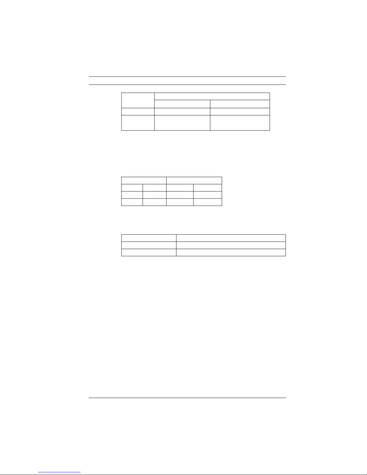
4.2 Power
The recommended power cable is a 2-conductor, 14-18 gage
cable, depending on the distance. Refer to the wiring distance
guide below.
VA / Watts 14 AWG
(2.5 mm)
24 VAC input 24 VA / 12 W 949 ft
(289 m)
12 VDC input 12 W 237 ft
(72 m)
Power connections
Follow the instructions in the table below to terminate the two
(2) power connections:
F01U079609 | 1.0 | 2008.08 Installation Manual Bosch Security Systems, Inc.
16 AWG
(1.5 mm)
597 ft
(182 m)
149 ft
(45 m)
18 AWG
(1.0 mm)
376 ft
(115 m)
94 ft
(29 m)
AutoDome Easy IP Preparing the Wiring | en 19
Description
Wire color
24 VAC operation +12 VDC operation
Red AC + (positive) DC + (positive)
Orange AC – (negative) DC – (negative) (DC
common or ground)
4.3 Alarm
The recommended optional alarm input cable is a 2-conductor,
18-22 gage cable, depending on the distance. Refer to the
wiring distance guide below.
Wire size Maximum distance
AWG mm feet meters
22 0.644 500 152.4
18 1.024 800 243.8
Alarm connections
Follow the instructions in the table below to terminate the two
(2) alarm connections:
Wire color Description
Blue Alarm Common
Violet Alarm In
Bosch Security Systems, Inc. Installation Manual F01U079609 | 1.0 | 2008.08
20 en | Connections AutoDome Easy IP
5 Connections
5.1 Connecting to the Ethernet
The AutoDome Easy IP camera can be controlled remotely by an
external device or by the AutoDome Easy IP web interface.
Note: In rare cases it may take up to three (3) minutes for the
dome to fully boot-up and for the Ethernet network to be active.
5.2 Connecting the Power
WARNING!
This unit accepts 24 VAC or 12 VDC, 1 A power only. Do not
!
connect 120 V or 230 V to this camera.
The AutoDome Easy IP accepts 24 VAC or 12 VDC power input.
If you are connecting the unit to the 12 VDC power input, take
care to connect the positive red lead to the positive power
input lead and connect the negative orange lead to the negative
(DC common or ground) power input lead.
If you are connecting the unit to a 24 VAC power input, the
connection of the leads does not matter.
To connect the power, do the following:
1. Locate the cable assembly with a two (2) pin mating
connector on one end and the red and orange flying leads
on the other end.
2. If connecting to the 12 VDC power input:
a. Connect the positive red lead to the positive power
input lead.
b. Connect the negative orange lead to the negative (DC
common or ground) power input lead.
3. If connecting to the 24 VAC power input, connect the red
lead to one power input lead. Then connect the orange
lead to the other power input lead.
NOTICE!
i
Use certified/listed Class 2 power supply transformer only.
F01U079609 | 1.0 | 2008.08 Installation Manual Bosch Security Systems, Inc.
AutoDome Easy IP Connections | en 21
5.3 Connecting the Alarm Input
The AutoDome Easy IP provides one (1) alarm input. This alarm
input can be activated by dry contact devices, which can be set
to: alert the operator via on-screen test or through the web
browser; trigger the dome to move to a pre-position, if
configured properly; automatically establish a connection with
a receiving device; and send an alarm e-mail. The default alarm
state is normally open but may be programmed to be normally
closed. To connect the alarm input, do the following:
1. Locate the cable assembly with a two (2) pin blue mating
connector on one end and the blue and violet flying leads
on the other end.
2. Connect the ground of the alarm source dry contact to the
blue wire (alarm common).
3. Connect the alarm out of the alarm source dry contact to
the violet wire (alarm input).
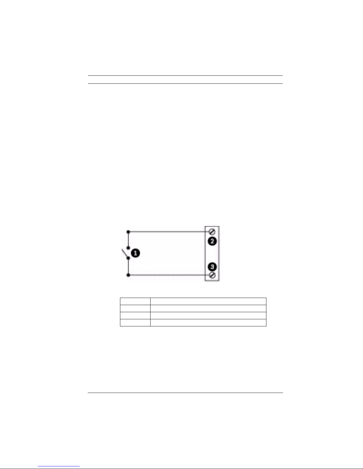
Figure 5.1 N.O. - Normally Open Alarm Connections
Reference Description
1Dry Contact
2 Alarm Common (blue wire)
3 Alarm Input (violet wire)
Bosch Security Systems, Inc. Installation Manual F01U079609 | 1.0 | 2008.08
22 en | Mounting Installation AutoDome Easy IP
6 Mounting Installation
This installation should be made by qualified service personnel
and conform to the National Electrical Code and applicable
local codes. This chapter details how to install the AutoDome
Easy IP for a surface (ceiling/wall) mount (supplied separately).
NOTICE!
Grounded conduit is required in order to meet the EMC
i
Regulation Requirements.
6.1 Installing the Wall Mount
1. Determine a secure location for the wall mount (supplied
separately).
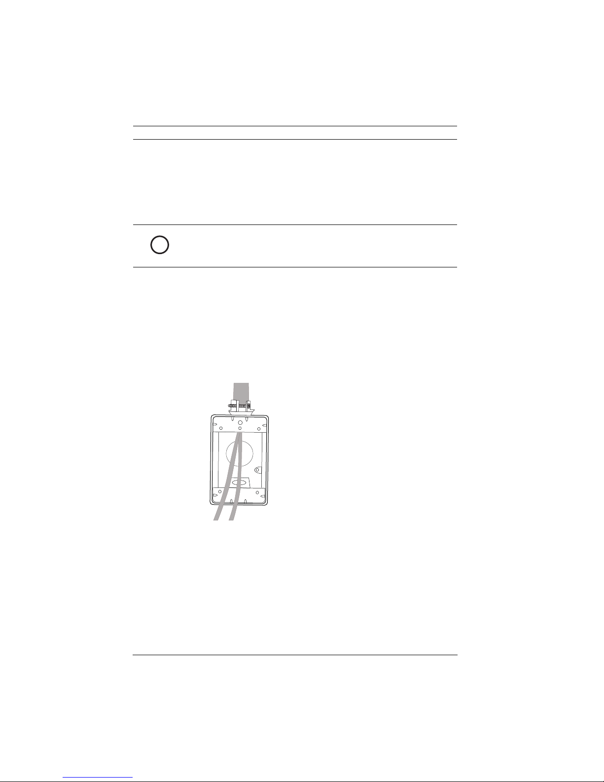
2. Fit a user-provided metal single-gang junction box to the
wall.
3. Attach a grounded metal conduit to the junction box
clamp.
Figure 6.1 Metal conduit
4. Feed the wires through the conduit.
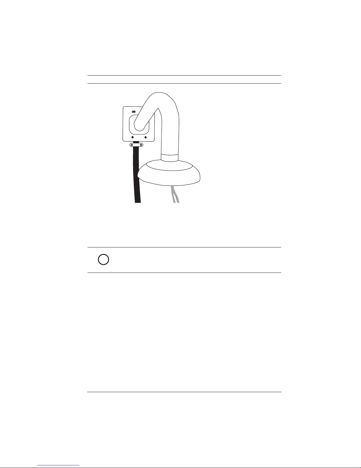
5. Feed all wires from the metal junction box through the
6. Attach the mounting cap to the arm.
7. Fit the arm to a metal single-gang junction box.
F01U079609 | 1.0 | 2008.08 Installation Manual Bosch Security Systems, Inc.
arm.
AutoDome Easy IP Mounting Installation | en 23
Figure 6.2 Fit to gang junction box
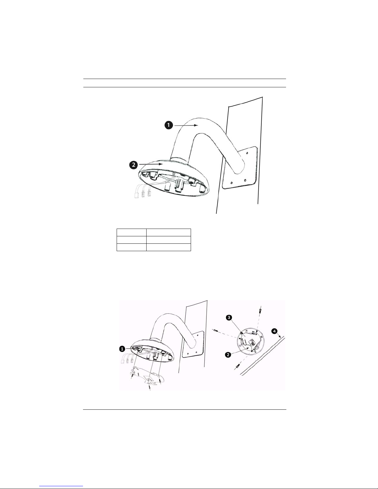
8. Secure with the appropriate user-provided SEMS screws
that have an integral lock washer to dig through the paint
and ensure an electrical ground connection to the arm
housing.
NOTICE!
The metal junction box and mounting surface must be capable
i
of supporting a maximum load of 11.33 kg (25 pounds).
Bosch Security Systems, Inc. Installation Manual F01U079609 | 1.0 | 2008.08
24 en | Mounting Installation AutoDome Easy IP
Figure 6.3 Attaching the mount to the wall
Number Description
1Arm
2Cap
9. Attach the mounting plate (supplied with dome) to the
dome mounting cap with the three (3) screws supplied.
Ensure that the mounting plate's "front" end, as labeled on
the plate, is screwed into the threaded stud furthest away
from the wall (180 degrees), as shown in Figure 6.4.
Figure 6.4 Attaching the mounting plate to the dome cap
F01U079609 | 1.0 | 2008.08 Installation Manual Bosch Security Systems, Inc.
 Loading...