

Bosch UMS-20S36A-B20, UMS-20S36C-B20, UMS-20W39A-B20, UMS-20W39C-B20 Installation Manual
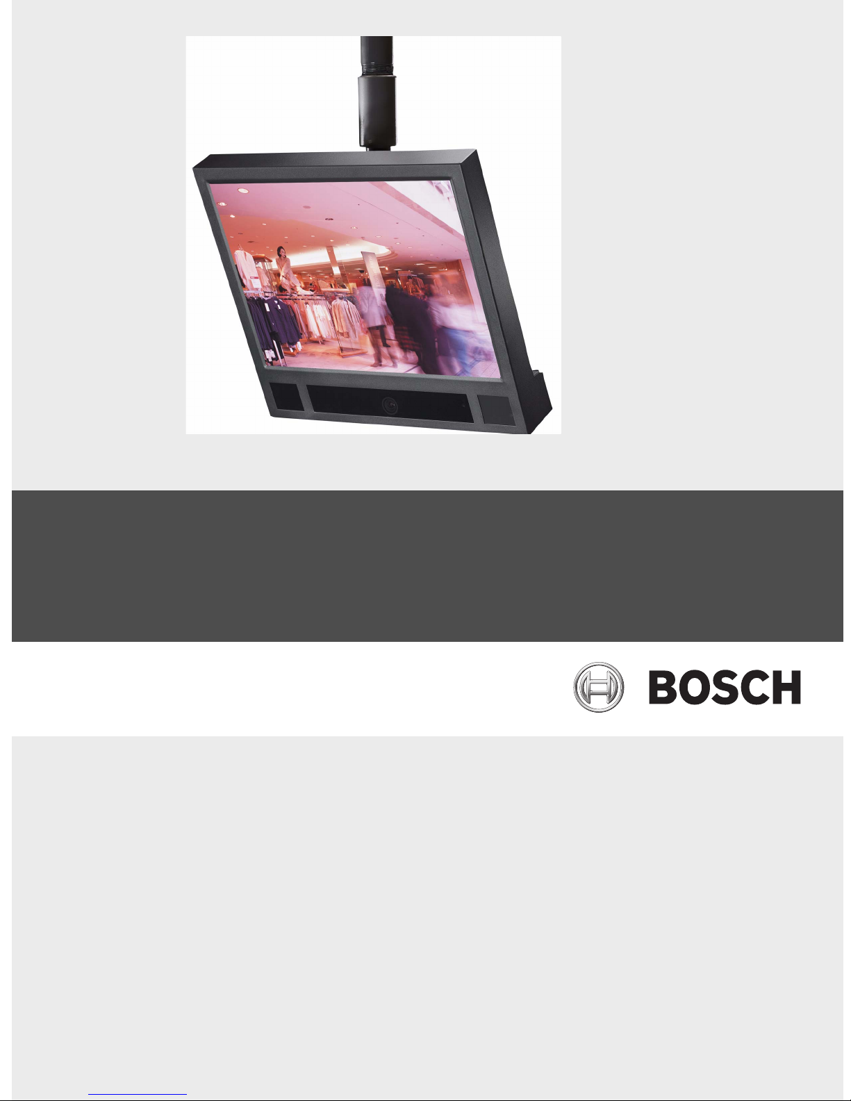
UMS Series Public View Monitor
UMS-20xxxA and UMS-20xxxC
en Installation Manual

en iii
Important Safeguards
1. Read, Follow, and Retain Instructions - All safety and operating instructions should be read and followed before operating the unit. Retain instructions for future reference.
2. Heed Warnings - Adhere to all warnings on the unit and in
the operating instructions.
3. Attachments - Attachments not recommended by the product manufacturer should not be used, as they may cause
hazards.
4. Installation Cautions - Do not place this unit on an unstable
stand, tripod, bracket, or mount. The unit may fall, causing
serious injury to a person and serious damage to the unit.
Use only manufacturer-recommended accessories, or those
sold with the product. Mount the unit per the manufacturer's instructions. Appliance and cart combination should
be moved with care. Quick stops, excessive force, or
uneven surfaces may cause the appliance and cart combination to overturn.
5. Cleaning - Unplug the unit from the outlet before cleaning.
Follow any instructions provided with the unit. Generally,
using a damp cloth for cleaning is sufficient. Do not use liquid cleaners or aerosol cleaners.
6. Servicing - Do not attempt to service this unit yourself.
Opening or removing covers may expose you to dangerous
voltage or other hazards. Refer all servicing to qualified service personnel.
7. Damage Requiring Service - Unplug the unit from the main
AC power source and refer servicing to qualified service
personnel under the following conditions:
• When the power supply cord or plug is damaged.
• If liquid has been spilled or an object has fallen into the
unit.
• If the unit has been exposed to water and/or inclement
weather (rain, snow, etc.).
• If the unit does not operate normally, when following
the operating instructions. Adjust only those controls
specified in the operating instructions. Improper adjustment of other controls may result in damage, and
require extensive work by a qualified technician to
restore the unit to normal operation.
• If the unit has been dropped or the cabinet damaged.
• If the unit exhibits a distinct change in performance, this
indicates that service is needed.
8. Replacement Parts - When replacement parts are required,
the service technician should use replacement parts specified by the manufacturer or that have the same characteristics as the original part. Unauthorized substitutions may
result in fire, electrical shock or other hazards.
9. Safety Check - Upon completion of servicing or repairs to
the unit, ask the service technician to perform safety
checks to ensure proper operating condition.
10.Power Sources - Operate the unit only from the type of
power source indicated on the label. If unsure of the type of
power supply to use, contact your dealer or local power
company.
• For units intended to operate from battery power, refer
to the operating instructions.
• For units intended to operate with External Power Sup-
plies, use only the recommended approved power supplies.
• For units intended to operate with a limited power
source, this power source must comply with EN60950.
Substitutions may damage the unit or cause fire or
shock.
• For units intended to operate at 24VAC, normal input
voltage is 24VAC. Voltage applied to the unit's power
input should not exceed 30VAC.
User-supplied wiring, from the 24VAC supply to unit, must
be in compliance with electrical codes (Class 2 power levels). Do not ground the 24VAC supply at the terminals or at
the unit's power supply terminals.
11.Coax Grounding - If an outside cable system is connected
to the unit, ensure that the cable system is grounded.
U.S.A. models only - Section 810 of the National Electrical
Code, ANSI/NFPA No.70, provides information regarding
proper grounding of the mount and supporting structure,
grounding of the coax to a discharge unit, size of grounding
conductors, location of discharge unit, connection to
grounding electrodes, and requirements for the grounding
electrode.
12.Grounding - This unit may be equipped with a 3-wire
grounding plug (a plug with a third pin, for grounding). This
safety feature allows the plug to fit into a grounding power
outlet only. If unable to insert the plug into the outlet, contact an electrician to arrange replacement of the obsolete
outlet. Do not defeat the safety purpose of the grounding
plug.
• Outdoor equipment should only be connected to the
unit's inputs after this unit has had its grounding plug
connected to a grounded outlet or its ground terminal
properly connected to a ground source.
• The unit's input connectors must be disconnected from
outdoor equipment before disconnecting the grounding
plug or grounding terminal.
• Proper safety precautions such as grounding should be
followed for any outdoor device connected to this unit.
13.Lightning - For added protection during a lightning storm,
or when this unit is left unattended and unused for long
periods of time, unplug the unit from the wall outlet and
disconnect the cable system. This will prevent damage to
the unit due to lightning and power line surges.
F01U029703 | 1.0 | 2006.07 Bosch Security Systems, Inc.
iv en
For Indoor Product
1. Water and Moisture - Do not use this unit near water for example, in a wet basement, in an unprotected outdoor installation or in any area classified as a wet location.
2. Object and Liquid Entry - Never push objects of any
kind into this unit through openings, as they might touch
dangerous voltage points or create short circuits, resulting in a fire or electrical shock. Never spill liquid of any
kind on the unit.
3. Power Cord and Power Cord Protection - For units
intended to operate with 230VAC, 50Hz, the input and
output power cord must comply with the latest versions
of IEC Publication 227 or IEC Publication 245. Power
supply cords should be routed so they are not likely to
be walked on or pinched. Pay particular attention to
location of cords and plugs, convenience receptacles,
and the point of exit from the appliance.
4. Overloading - Do not overload outlets and extension
cords; this can result in a risk of fire or electrical shock.
For Outdoor Product
Power Lines - An outdoor system should not be located
in the vicinity of overhead power lines, electric lights or
power circuits, or where it may contact such power lines
or circuits. When installing an outdoor system, extreme
care should be taken to keep from touching power lines
or circuits, as this contact might be fatal. U.S.A. models
only - refer to the National Electrical Code Article 820
regarding installation of CATV systems.
For Rack-mount Product
1. Ventilation - Do not place this equipment in a built-in
installation or rack, unless proper ventilation is provided, or the manufacturer's instructions were followed.
The equipment must not exceed its maximum operating
temperature requirements.
2. Mechanical Loading - When rack-mounting the equipment, ensure that a hazardous condition is not created
by uneven mechanical loading.
WARNING:
Electrostatic-sensitive device. Use proper CMOS/
MOSFET handling precautions to avoid electrostatic discharge.
NOTE: Grounded wrist straps must be worn and
proper ESD safety precautions observed when
handling the electrostatic-sensitive printed circuit
boards.
This symbol indicates the presence of important
operating and maintenance (servicing) instructions in the literature accompanying the appliance.
Cover Removal
Warning: Removal of the cover should only be
performed by qualified service personnel - not
user serviceable. The unit should always be
unplugged before removing the cover and remain
unplugged while the cover is removed.
24 VAC Units
Do not exceed 30VAC input. Voltage applied to the unit's
power input should not exceed 30VAC. Normal input voltage is
24VAC. User supplied wiring from 24VAC supply to unit must
be in compliance with electrical codes (Class 2 power levels).
Do not ground 24VAC supply at power supply terminals or at
unit's power supply terminals.
This equipment is to be isolated from the mains
supply by a limited power source as specified in
EN60950.
220-240V, 50Hz Power Cords
220-240V, 50Hz power cords, input and output, must comply
with the latest versions of IEC Publication 227 or IEC Publication 245.
Bosch Security Systems, Inc. F01U029703 | 1.0 | 2006.07
en v
FCC & ICES INFORMATION
(U.S.A. and Canadian Models Only)
This device complies with part 15 of the FCC Rules. Operation
is subject to the following two conditions:
(1)This device may not cause harmful interference, and
(2)This device must accept any interference received, includ-
ing interference that may cause undesired operation.
NOTE: This equipment has been tested and found to comply
with the limits for a Class A digital device, pursuant to Part 15
of the FCC Rules and ICES-003 of Industry Canada. These limits are designed to provide reasonable protection against
harmful interference when the equipment is operated in a
commercial environment. This equipment generates, uses and
radiates radio frequency energy, and if not installed and used
in accordance with the instruction manual, may cause harmful
interference to radio communications. Operation of this equipment in a residential area is likely to cause harmful interference, in which case the user will be required to correct the
interference at his expense.
Intentional or unintentional changes or modifications, not
expressly approved by the party responsible for compliance,
shall not be made. Any such changes or modifications could
void the user’s authority to operate the equipment. If necessary, the user should consult the dealer or an experienced
radio/television technician for corrective action. The user may
find the following booklet, prepared by the Federal Communications Commission, helpful: How to Identify and Resolve Radio-
TV Interference Problems. This booklet is available from the U.S.
Government Printing Office, Washington, DC 20402, Stock No.
004-000-00345-4.
WARNING: This is a Class A product. In a domestic environment, this product may cause radio interference, in which
case, the user may be required to take adequate measures.
Safety Precautions
CAUTION: TO REDUCE THE RISK OF ELECTRIC SHOCK, DO
NOT REMOVE COVER (OR BACK). NO USER SERVICEABLE
PARTS INSIDE. REFER SERVICING TO QUALIFIED SERVICE
PERSONNEL.
This symbol indicates the presence of uninsulated
“dangerous voltage” within the product’s enclosure that can cause an electric shock.
This symbol indicates the presence of important
operating and maintenance (servicing) instructions in the literature accompanying the appliance.
Installation should be performed by qualified service personnel only in accordance with the
National Electrical Code or applicable local codes.
Power Disconnect. Units with or without ON-OFF
switches have power supplied to the unit whenever the power cord is inserted into the power
source; however, the unit is operational only when
the ON-OFF switch is in the ON position. The
power cord is the main power disconnect for all
units.
F01U029703 | 1.0 | 2006.07 Bosch Security Systems, Inc.
vi en
INFORMATIONS FCC ET ICES
(modèles utilisés aux États-Unis et au Canada uniquement)
Ce produit est conforme aux normes FCC partie 15. la mise en
service est soumises aux deux conditions suivantes:
(1) cet appareil ne peut pas provoquer d'interférence nuisible
et
(2) cet appareil doit pouvoir tolérer toutes les interférences
auxquelles il est soumit, y compris les interférences qui
pourraient influer sur son bon fonctionnement.
AVERTISSEMENT: Suite à différents tests, cet appareil s’est
révélé conforme aux exigences imposées aux appareils
numériques de Classe A en vertu de la section 15 du règlement
de la Commission fédérale des communications des États-Unis
(FCC). Ces contraintes sont destinées à fournir une protection
raisonnable contre les interférences nuisibles quand l'appareil
est utilisé dans une installation commerciale. Cette appareil
génère, utilise et émet de l'energie de fréquence radio, et peut,
en cas d'installation ou d'utilisation non conforme aux instructions, générer des interférences nuisibles aux communications
radio. L’utilisation de ce produit dans une zone résidentielle
peut provoquer des interférences nuisibles. Le cas échéant,
l’utilisateur devra remédier à ces interférences à ses propres
frais.
Au besoin, l’utilisateur consultera son revendeur ou un technicien qualifié en radio/télévision, qui procédera à une opération corrective. La brochure suivante, publiée par la
Commission fédérale des communications (FCC), peut
s’avérer utile : « How to Identify and Resolve Radio-TV Interference Problems » (Comment identifier et résoudre les
problèmes d’interférences de radio et de télévision). Cette
brochure est disponible auprès du U.S. Government Printing
Office, Washington, DC 20402, États-Unis, sous la référence n°
004-000-00345-4.
Avertissement : Ce produit est un appareil de Classe A. Son
utilisation dans une zone résidentielle risque de provoquer
des interférences. Le cas échéant, l’utilisateur devra prendre
les mesures nécessaires pour y remédier.
Sécurité
Attention : l'installation doit exclusivement être réalisée par du
ATTENTION : POUR ÉVITER TOUT RISQUE D'ÉLECTROCUTION, N'ESSAYEZ PAS DE RETIRER LE CAPOT (OU LE PANNEAU ARRIÈRE). CET APPAREIL NE CONTIENT AUCUN
COMPOSANT SUSCEPTIBLE D'ÊTRE RÉPARÉ PAR L'UTILISATEUR. CONFIEZ LA RÉPARATION DE L'APPAREIL À DU
PERSONNEL QUALIFIÉ.
Ce symbole signale que le produit renferme une «
tension potentiellement dangereuse » non isolée
susceptible de provoquer une électrocution.
Ce symbole invite l'utilisateur à consulter les
instructions d'utilisation et d'entretien (dépannage) reprises dans la documentation qui
accompagne l'appareil.
Attention: l'installation doit exclusivement être
réalisée par du personnel qualifié, conformément
au code national d'électricité américain (NEC) ou
au code d'électricité local en vigueur.
Coupure de l'alimentation. Qu'ils soient pourvus
ou non d'un commutateur ON/OFF, tous les appareils reçoivent de l'énergie une fois le cordon
branché sur la source d'alimentation. Toutefois,
l'appareil ne fonctionne réellement que lorsque le
commutateur est réglé sur ON. Le débranchement
du cordon d'alimentation permet de couper l'alimentation des appareils.
Bosch Security Systems, Inc. F01U029703 | 1.0 | 2006.07
AVERTISSEMENT:
cet appareil est sensible aux décharges électrostatiques. Pour éviter tout risque de décharge élec-
trostatique, observez les précautions de
manipulation du CMOS/MOSFET appropriées.
REMARQUE : lors de la manipulation des cartes à
circuits imprimés sensibles aux décharges électrostatiques, portez des bracelets antistatiques
mis à la terre et observez les consignes de sécurité relatives aux décharges électrostatiques.
ATTENTION : pile au lithium
Le remplacement incorrect de la pile risque de
provoquer une explosion. Remplacez la pile exclusivement par une pile identique ou par un type de
pile équivalent recommandé par le fabricant.
Débarrassez-vous de la pile usagée conformément
aux instructions de son fabricant.
Enlèvement du capot
Avertissement : L’enlèvement du capot ne doit
être effectué que par un technicien spécialisé. Il
n’y a pas de pièces remplaçables ou réglables par
l’utilisateur. Il faut toujours débrancher l’appareil
avant d’enlever le capot et le laisser débranché
jusqu’à la remise en place du capot.
en vii
24 VAC Units
Ne pas excéder 30 V c.a. La tension appliquée à l’entrée d’alimentation de l’appareil ne doit pas excéder 30 V c.a. La valeur
normale de la tension d’entrée est 24 V c.a. Le circuit électrique reliant l’alimentation 24 V c.a. à l’appareil doit être conforme aux codes électriques (niveaux d’alimentation de classe
2). Ne pas mettre l’alimentation 24 V c.a. à la masse au niveau
des bornes de l’alimentation ou de l’appareil.
Cet équipement doit être isolé de l’alimentation
secteur par une source de puissance limitée, conformément à la norme EN60950.
Cordons d’alimentation 220-240 V, 50 Hz
Les cordons d’alimentation 220-240 V, 50 Hz, d’entrée ou de
sortie, doivent être conformes à la dernière version de la publication IEC 227 ou IEC 245.
F01U029703 | 1.0 | 2006.07 Bosch Security Systems, Inc.

viii en
Bosch Security Systems, Inc. F01U029703 | 1.0 | 2006.07

UMS Series Public View Monitor | en ix
Preface
This guide describes how to install and configure the UMS Series Public View Monitor.
Audience
This guide is intended for qualified installation and service personnel who are familiar with the applicable national
and local electrical codes.
Document Conventions
Convention Meaning
Bold Denotes a part, item, or assembly.
Bold Italic Denotes a reference to another paragraph, figure or table.
Underline
Customer Support and Service
If this unit needs service, contact the nearest Bosch Security Systems Service Center for authorization to return and
shipping instructions.
Service Centers
USA
Phone: 800-366-2283 or 585-340-4162
Fax: 800-366-1329
Email: cctv.repair@us.bosch.com
CCTV Spare Parts
Phone: 800-894-5215 or 408-957-3065
Fax: 408-935-5938
Email: BoschCCTVparts@ca.slr.com
Canada
Phone: 514-738-2434
Fax: 514-738-8480
Europe, Middle East & Asia Pacific Region
Phone: 44 (0) 1495 274558
Fax: 44 (0) 1495 274280
Email: rmahelpdesk@solectron.com
For additional information, see www.boschsecurity.com
Used to emphasize a point.
Related Publications
Refer to the latest Bosch Security Systems Databook for the most up-to-date datasheets. To obtain a copy of the
Databook, please contact your local Bosch representative.
You can also visit the Bosch Security Systems World Wide Web site at:
http://www.boschsecurity.com to view a current listings of our publications.
Bosch Security Systems, Inc. Installation Manual F01U029703 | 1.0 | 2006.07

x en | UMS Series
F01U029703 | 1.0 | 2006.07 Installation Manual Bosch Security Systems, Inc.

UMS Series Public View Monitor Table of Contents | en xi
Table of Contents
1 Unpacking 1
1.1 Parts List 1
2Description 2
2.1 General Features 2
2.2 UMS Series Models 2
3 Installing the UMS Series 3
3.1 Power 3
3.2 Mounting 3
3.3 Power Connection 4
3.4 Video Connections 4
3.5 Remote Control Battery Installation 5
4 Monitor Remote Control Functions (Bosch) 6
4.1 Monitor Remote Control Operating Modes 7
4.2 Navigating the Monitor On-screen Display (OSD) 7
4.3 Monitor Remote Control On-screen Display Menus 7
4.4 Input Select Menu 9
5 Using the Card Reader 10
5.1 Compatible Flash Memory Cards 10
5.2 Image Requirements 10
6 Card Reader Remote Control Functions (SanDisk®) 12
6.1 Card Reader On-screen Display Menu Selections 12
6.2 Card Reader Menu Selections 13
7 Configuring Motion Detection 16
7.1 Selecting a Mounting Location 16
7.2 Activating the PIR 16
8 Camera Tilt and Pivot Adjustments 17
8.1 High-resolution Color Series Camera 17
8.2 Dip Switch Location for the High-resolution Color Camera 18
8.3 Wide Dynamic Range (WDR) Series Camera 19
8.4 Dip Switch Location for Wide Dynamic Range (WDR) Camera 19
8.5 Focusing the Camera 20
8.6 Light Sensor 20
Bosch Security Systems, Inc. Installation Manual F01U029703 | 1.0 | 2006.07

xii en | Table of Contents UMS Series Public View Monitor
9 Troubleshooting 21
9.1 Make adjustments to the control board and option switches 21
9.2 Screen flickers 22
9.3 No video displayed 23
9.4 Only displays Power Save mode 23
9.5 Remote control does not activate the monitor 24
9.6 Lost remote control 24
9.7 Memory card images appear stretched and out of proportion 25
9.8 Images are smaller than the recommended size 25
9.9 Question marks are displayed in the preview mode 25
9.10 Movie clips do not play 25
9.11 Card reader does not display images 25
9.12 Monitor does not display AUTO or AUX video when turned on 26
10 UMS Ordering Information 27
10.1 Power Supply 27
10.2 Mounting Options 27
10.3 Replacement Parts 27
11 Specifications 28
F01U029703 | 1.0 | 2006.07 Installation Manual Bosch Security Systems, Inc.
UMS Series Public View System Unpacking | en 1
1 Unpacking
This equipment should be unpacked and handled with care. If an item appears to have been
damaged in shipment, notify the shipper. Verify that all parts shown in the Parts List are
included. If any items are missing, notify your Bosch Security Systems Sales or Customer Service Representative.
The original packing carton is the safest container in which to transport the unit. Save it for
possible future use.
1.1 Parts List
The following table lists the components that comes with all UMS Series systems:
Qty Item
1UMS LCD monitor
1 Monitor remote control (Bosch) with two (2) AAA batteries
2 Wago® clamps, used to connect the power leads from the UMS Public View Monitor
and the leads from the power supply.
1 This installation manual
i
The following additional equipment comes with the UMS-20xxxC Series models:
1 Memory card reader (SanDisk) remote control with two (2) AAA batteries
(UMS-20xxxC models only)
NOTICE! It is recommended that you do not remove the clear protective plastic covers on the
UMS at this time.
Bosch Security Systems, Inc. Installation Manual F01U029703 | 1.0 | 2006.07

2 en | Description UMS Series Public View System
2Description
The Universal Monitor System (UMS) Series provides video surveillance and advertising display in one system. It contains an LCD display, a hidden CCTV camera, a built-in memory card
reader*, and motion and light sensors.
The UMS 20xxxC Series, with an optional integrated memory card reader, displays images
from a Flash memory card reader.
The motion sensor allows the UMS Series to switch from displaying logos or advertising to displaying a message that alerts viewers to the use of surveillance equipment. The light sensor
detects low light levels, which triggers the UMS Series to power down the monitor while the
camera continues to film.
The UMS Series also features feed-through wiring and a button-less housing, to minimize
unauthorized tampering, and a remote control to control the optional card reader. See
Section 4, Monitor Remote Control Functions (Bosch), on page 6 for more information.
2.1 General Features
The UMS Series features a 20.1-inch LCD flat-panel monitor with either a high resolution color
camera (3–6 mm lens) or a wide dynamic range camera (3.8–9.5 mm lens). The UMS Series is
equipped with a varifocal, auto iris lens, has 640 x 480 pixels resolution, includes four (4)
memory card reader slots, features advanced power management, and supports plug and play
technology.
2.2 UMS Series Models
Each UMS Series Public View system offers some or all of the following features:
– 20.1-inch LCD flat-panel monitor
– High resolution color and wide dynamic range camera options
– Integrated memory card reader for storing welcome messages, logos, or advertising
– Built-in motion sensor switches monitor from advertising to surveillance mode
– Light sensor that triggers the Monitor Sleep mode
– IR remote control and on-screen display for easy setup and control
– All cables are concealed
The following table lists a summary of features for each UMS model:
Model Number Features
UMS-20S36A-B20 20.1 inch LCD monitor with a high-resolution, color camera, 3–6 mm lens,
24 VAC, 60 Hz, motion sensor, light sensor, black cabinet
UMS-20S36C-B20 20.1 inch LCD monitor with a high-resolution, color camera and a memory
card reader, 3–6 mm lens, 24 VAC, 60 Hz, motion sensor, light sensor,
black cabinet
UMS-20W39A-B20 20.1 inch LCD monitor with a high-resolution, wide dynamic color camera,
3.8–9.5 mm lens, 24 VAC, 60 Hz, motion sensor, light sensor, black cabinet
UMS-20W39C-B20 20.1 inch LCD monitor with a high-resolution, wide dynamic color camera
and a memory card reader, 3.8–9.5 mm lens, 24 VAC, 60 Hz, motion sensor, light sensor, black cabinet
* Only available with UMS-20S36C-xxx and UMS-20W39C-xxx.
F01U029703 | 1.0 | 2006.07 Installation Manual Bosch Security Systems, Inc.
UMS Series Public View System Installing the UMS Series | en 3
3 Installing the UMS Series
This section provides instructions for installing and configuring the UMS Series.
CAUTION! Installation should be performed by qualified service installers only, using
construction methods in accordance with applicable local codes and standards.
!
3.1 Power
Model Rated Voltage Voltage Range Power at Rated Voltage Sync. Format
UMS
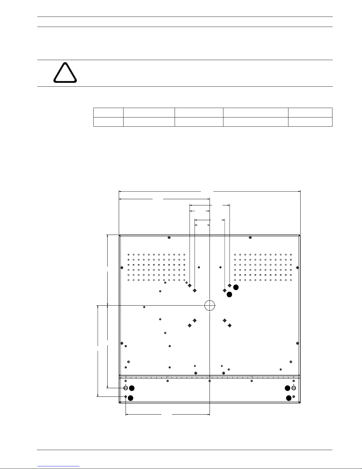
3.2 Mounting
The UMS Series has both 2.95-in. (75-mm) and 3.94-in. (100-mm) mounting hole patterns. The
holes are threaded for #10-24 screws with a maximum length of 3/8 in. (not provided with the
UMS Series). In addition, the UMS Series features two mounting holes in which you can attach
a sign to the UMS Series housing. The following illustration details the mounting hole patterns
on the back of the UMS monitor:
24 VAC, 60 Hz 22-26 VAC 80 W/100 VA NTSC
17.88
8.94
3.94
1.48
2.95
TYP
TYP
1.97
6.96
8.13
8.97
3 3
8.28
Fig. 3.1 UMS Series Mounting Hole Pattern
2
1
44
Bosch Security Systems, Inc. Installation Manual F01U029703 | 1.0 | 2006.07
 Loading...