

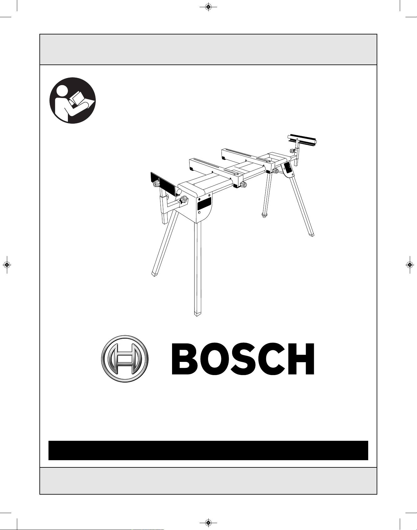
Bosch T1B Operating And Safety Instructions Manual
For English Version Version française Versión en español
See page 2 Voir page 13 Ver la página 24
Operating/Safety Instructions
Consignes de fonctionnement/sécurité
Instrucciones de funcionamiento y seguridad
IMPORTANT: IMPORTANT : IMPORTANTE:
Read Before Using Lire avant usage Leer antes de usar
1-877-BOSCH99 (1-877-267-2499) www.boschtools.com
Call Toll Free for
Consumer Information
& Service Locations
Pour obtenir des informations et
les adresses de nos centres de
service après-vente,
appelez ce numéro gratuit
Llame gratis para
obtener información
para el consumidor y
ubicaciones de servicio
T1B
2610001768_T1B 8/17/17 8:57 AM Page 1
Table of Contents
Table of Contents ....................................................2
Safety Instructions for Miter Saw Stands..................3
Unpacking and Checking Contents ..........................4
Getting to Know Your Miter Saw Stand ....................5
Assembly ..............................................................6-9
Adjustments ............................................................10
Operation ................................................................11
Maintenance ..........................................................12
2
Safety Symbols
The
def
init
ions
below
des
c
r
ibe
t
he
lev
el
of
s
ev
er
it
y
f
or
eac
h
s
ignal
w
or
d.
P
leas
e
r
ead
t
he
m
anual
and
pay
at
t
ent
ion
t
o
t
hes
e
s
y
m
bols
.
!
This
is
t
he
s
af
et
y
aler
t
s
y
m
bol.
I
t
is
us
ed
t
o
aler
t
y
ou
t
o
pot
ent
ial
per
s
onal
injur
y
haz
ar
ds
.
Obey
all
s
af
et
y
m
es
s
ages
t
hat
f
ollow
t
his
s
y
m
bol
t
o
av
oid
pos
s
ible
injur
y
or
deat
h.
D
A
N
GE
R
indic
at
es
a
haz
ar
dous
s
it
uat
ion
w
hic
h,
if
not
av
oided,
w
ill
r
es
ult
in
deat
h
or
s
er
ious
injur
y
.
W
A
R
N
I
N
G
indic
at
es
a
haz
ar
dous
s
it
uat
ion
w
hic
h,
if
not
av
oided,
c
ould
r
es
ult
in
deat
h
or
s
er
ious
injur
y
.
C
A
U
TI
ON
,
us
ed
w
it
h
t
he
s
af
et
y
aler
t
s
y
m
bol,
indic
at
es
a
haz
ar
dous
s
it
uat
ion
w
hic
h,
if
not
av
oided,
w
ill
r
es
ult
in
m
inor
or
m
oder
at
e
injur
y
.
2610001768_T1B 8/17/17 8:57 AM Page 2

3
Read all safety warnings and all
instructions. Failure to follow all
instructions listed below and in your miter saw manual
m
ay result in serious personal injury.
Fully ass e m b l e and tighte n al l the faste n e r s
required for this stand. Also remember to
occasionally check the stand and make sure it is
still tight. A loose stand is unstable and may shift in
use and cause serious injury.
Turn tool switch off and disconnect power before
mounting to the stand. Unintended startup during
assembly can cause injury.
Be fore o perati ng make sure the en tire unit i s
placed on a solid, flat, level surface. Serious injury
could occur if tool with stand is unstable and tips.
Never stand on tool or its stand or use as ladder or
scaffolding. Serious injury could occur if the tool is
tipped or the cutting tool is accidentally contacted. Do
not store materials on or near the tool such that it is
necessary to stand on the tool or its stand to reach
them.
Use only Bosch replacement parts. Any others may
create a hazard.
The Miter Saw should be firmly mounted to the stand
per the instruction manual.
After mounting t he Miter Saw to the stand, align,
position and balance the Miter Saw per the instruction
manual.
Before use, verify that all stand parts are free from
damage and/or deformity.
Before use, verify that all parts or components of the
stand are properly installed.
Before use, swing open each of the legs until the
pin clicks, locking the legs in position.
When mounting the Miter Saw to the stand, make sure
that the tool mounting brackets are in the “UNLOCK”
position, so the tool mount will engage with the rails. Be
sure to hold the saw until it is secured to prevent it from
falling off the rails. Mounting bracket locking knobs
should then be tightened.
When removing the Miter Saw from the stand, loosen
the mounting bracket locking knobs until they rotate to
the “UNLOCK” position. Hold the Miter Saw firmly to
prevent the saw from falling off the rails. Carefully
remove the Miter Saw.
Do not modify the stand in any manner or use the
stand for any purpose other than is stated in these
instructions.
Because cut material may cause the stand to become
unbalanced, always be sure the material is supported
properly. Also, if the piece being cut is placed far
beyond the work support, stand legs on the opposite
side may suddenly be lifted up du e to weight
imbalance. To prevent this from occurring, hold the
opposite side firmly before cutting.
Important Safety Instructions for Using
This Miter Saw Stand
This T1B Miter Saw Stand is designed to be used with the
following Bosch miter saws:
Other units may be compatible, but have not been verified for use with the T1B System.
Bosch Model Numbers:
GCM12SD, CM12SD, CM12, CM10GD, CM8S, 4212, 4212L, 4310, 4405, 4410, 4410L, 4412, 5412, 5412L,
3912, 3915, 3918, 3924
2610001768_T1B 8/17/17 8:57 AM Page 3
4
For yo u r ow n sa fety, never
connect plug to power source
outlet until all assembly steps are complete and until
you have read and understood the entire owner’s
manual.
Model T1B Miter Saw Stand is shipped complete in
one box.
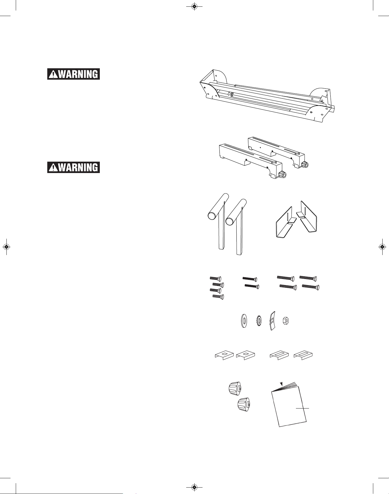
Unpacking and Checking Contents
Separate all parts from packing materials and check
each one with the “Table of Loose Parts” to make
sure all items are accounted for before discarding any
packing material.
If any parts are missing, do not
at tempt to assemble the stand
until the missing parts are obtained and are installed
correctly.
Table of Loose Parts
ITEM DESCRIPTION QTY.
A Miter Saw Stand 1
B Saw Mounting Brackets 2
C WorkSupports 2
D Work Stops 2
STAND ASSEMBLY HARDWARE
(packaged in one bag)
E Carriage Bolts (M8 x 26 mm) 4
F Carriage Bolts (M6 x 46 mm) 2
G Carriage Bolts (M8 x 44 mm) 4
H Flat Washers 4
I Lock Washers 4
J Bolt Retainer 2
K Nuts 4
L Short-Slot Sliding Mounting Plates 2
M Long-Slot Sliding Mounting Plates 2
N Work Stop Adjustment Knobs 2
O Operating Guide 1
Unpacking and Checking Contents
A
B
C
D
F
E
G
I
J
K
LM
N
O
H
2610001768_T1B 8/17/17 8:57 AM Page 4
5
3
1
8
9
5
6
2
4
2
7
Getting To Know Your Miter Saw Stand
1 Extension Adjustment Knob
2 Work Support
3 Extension Rail
4 Work Stop Adjustment Knob
5 Work Stop
6 Saw Mounting Bracket
7 Work Support Adjustment Knob
8 Bracket Locking Knob
9 Adjustable Foot
2610001768_T1B 8/17/17 8:57 AM Page 5
T
OOLS NEEDED FOR ASSEMBLY
• Adjustable wrench
• Phillips
®
screwdriver
P
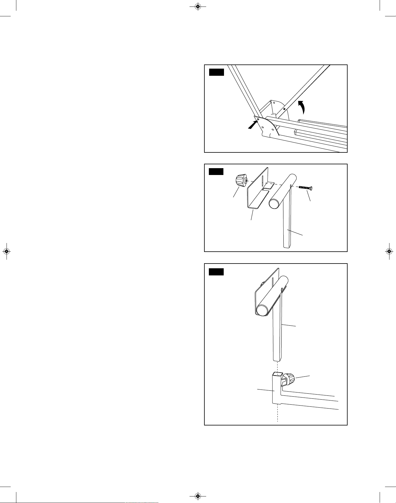
REPARING THE STAND
See Figure 1.
1. Lay the stand’s top surface down on the floor with
the folded legs on top.
2. Push in a leg locking pin (1) and rotate that leg up
until the locking pin clicks into place.
3. Repeat with the remaining three legs.
4. Lift the stand and place it in an upright position.
5. Check to ensure the stand is stable and all the legs
have the locking pins engaged.
ASSEMBLING AND INSTALLING
MATERIAL WORK SUPPORTS
See Figures 2 - 3.
The ma t e r i al wo r k su p p o r t s he l p bal a n c e the
workpiece during cutting operations.
To assemble the work support:
1. Slide a M6 x 46 mm carriage bolt (2) through the
square hole in the work support (3) and extend
through the other side.
2. Place the work stop (4) over the end of the bolt.
3. Thread a work stop adjustment knob (5) over the
end of the bolt and tighten to secure.
To install the work supports:
1.Slide the work support (3) into the extension rail (6).
Position the work support at the desired height on
the extension rail and tighten (7) in place.
2.Repeat with the other support.
6
FIG. 1
FIG. 2
FIG. 3
Assembly
2
3
5
1
4
3
7
6
2610001768_T1B 8/17/17 8:57 AM Page 6
7
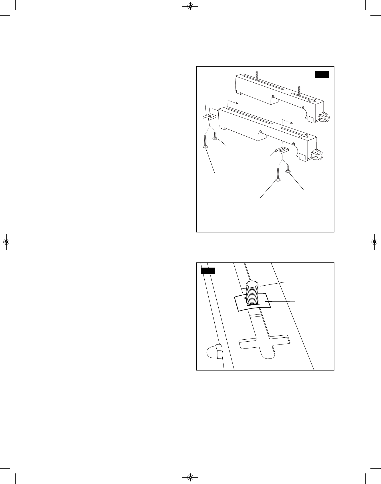
PREPARING SAW MOUNTING BRACKETS
For GCM12SD, CM12SD, CM12, CM10GD, CM8S
Miter Saws:
See Figure 4.
1.Place a Long-Slot Sliding Mounting Plate (1) onto two
of the M8 x 26 mm carriage bolts and feed them into
t
he front of the mounting bracket as shown in figure
4.
2.Place a Short-Slot Sliding Mounting Plate (2) onto
two of the M8 x 26 mm carriage bolts and feed them
into the rear of the mounting bracket as shown in
figure 4.
For 5412(L), 4212(L), and 3912 Miter Saws:
See Figure 4.
1.Place a Long-Slot Sliding Mounting Plate (1) onto two
of the M8 x 44 mm carriage bolts and feed them into
the front of the mounting bracket as shown in figure
4.
2.Place a Short-Slot Sliding Mounting Plate (2) onto
two of the M8 x 44 mm carriage bolts and feed them
into the rear of the mounting bracket as shown in
figure 4.
For 4410(L) and 4405 Miter Saws:
See Figure 4 & 5.
1.Place a Long-Slot Sliding Mounting Plate (1) onto
each of the M8 x 26 mm carriage bolts and feed them
into the front of the mounting bracket as shown in
figure 4.
2.Before sliding the mounting plate all the way forward,
thread a Bolt Retainer (3) onto each bolt as shown in
figure 5. When threaded completely, this will prevent
the shorter bolt from falling below the top surface of
the tool mount.
3.Place a Short-Slot Sliding Mounting Plate (2) onto
two of the M8 x 44 mm carriage bolts and feed them
into the rear of the mounting bracket as shown in
figure 4.
Note: The Long-Slot Sliding Mounting Plate will align
with the horizontal slot at the front of the mounting
bracket to accommodate Bosch miter saws with offset
mounting holes (5412(L), 4410(L) and 4212(L)).
Assembly
FIG. 5
3
M8 x 26 mm
[4410(L) & 4405
miter saws]
FIG. 4
M8 x 44 mm
[5412(L), 4212(L),
and 3912 miter
saws]
M8 x 44 mm
[5412(L), 4212(L),
4410(L), 4405, and
3912 miter saws]
M8 x 26 mm
[GCM12SD,
CM12SD, CM12
CM10GD, CM8S
miter saws]
M8 x 26 mm
[GCM12SD,
CM12SD, CM12,
CM10GD,
CM8S4410(L) and
4405 miter saws]
1
2
2610001768_T1B 8/17/17 8:57 AM Page 7
8
ATTACHING SAW TO
SAW MOUNTING BRACKETS
See Figure 6 and 7.
Always position the saw to achieve maximum balance
and stability. All four corners of the saw must be
bolted to the mounting brackets before use.
Your saw should have four holes that line up with
the slots in the saw mounting brackets:
1. Unplug the saw and lock the saw arm in the down
position.
2. Lift one side of the saw and place a saw mounting
bracket underneath, aligning the carriage bolts with
the miter saw mounting holes, as shown in figure 6.
Note: For saws with offset hole configurations,
slide the front bolt left or right to properly align the
tool to the mounting bracket as in Figure 7.
3. Lower the saw down onto the bracket, feeding the
carriage bolts through the mounting holes.
4. Secure in place using a flat washer (4), lock washer
(5), and nut (6).
5. Repeat steps 1 through 4 to install second bracket
to the other side of the saw.
6. After making sure both brackets are parallel to each
other, finger tighten all four nuts to hold in position.
(See page 9 for mounting saw to the stand and final
instructions on tightening nuts to properly secure
saw to mounting brackets.)
Assembly
FIG. 7
FIG. 6
6
5
4
2610001768_T1B 8/17/17 8:57 AM Page 8
9
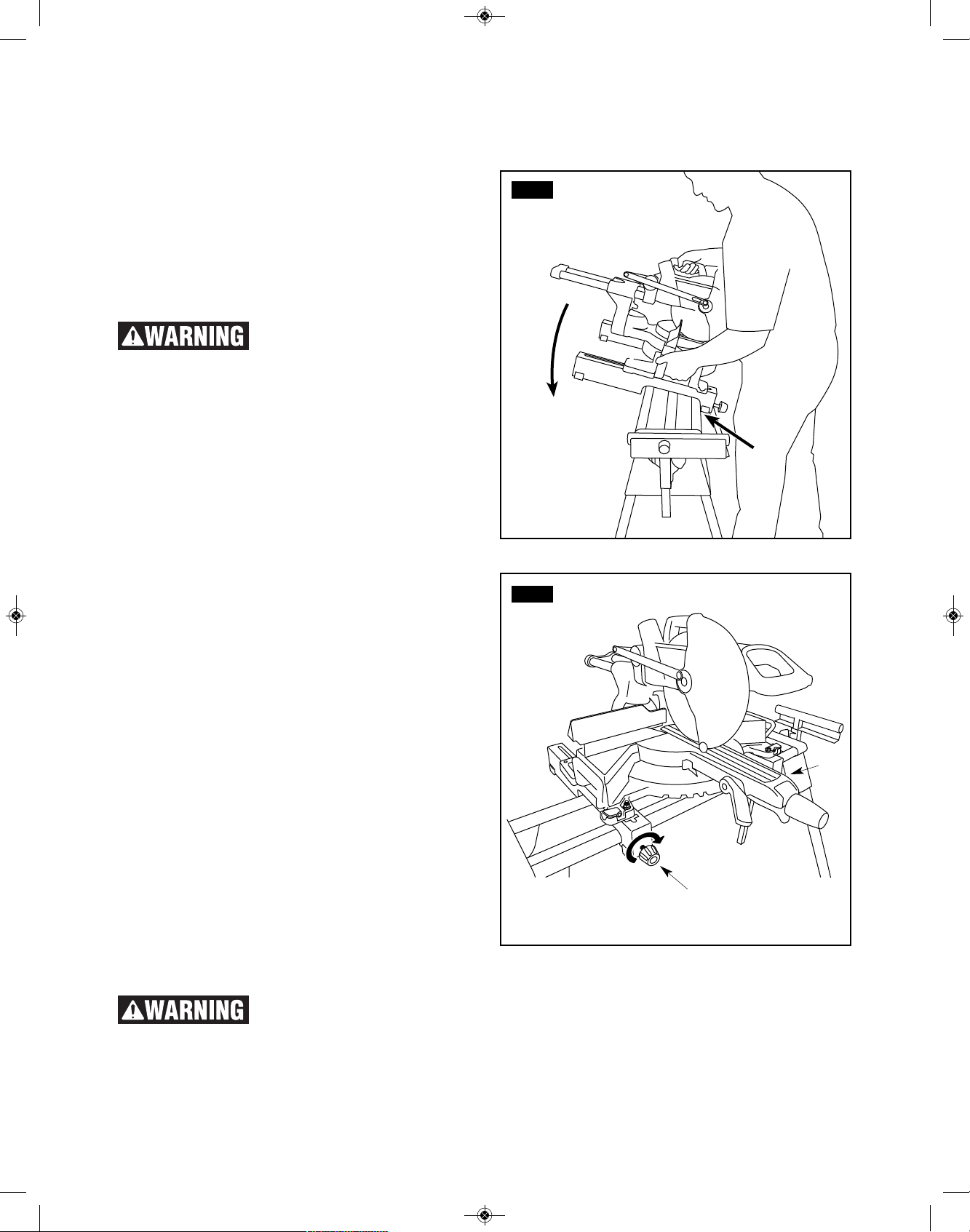
MOUNTING THE MITER SAW TO THE STAND
S
ee Figures 8 - 9.
1. Lift the saw and bracket assembly, allowing the
a
ssembly to tilt slightly toward your body.
2. While still tilted toward you, hook the front edge of
the bracket assembly onto the front rail (1) of the
stand, figure 8.
To avoid se r i o us per s o n a l
injury, make sure the curved
front edge of the mounting brackets are securely
seated over the front rail before seating the other
end of the brackets. Failure to do so could cause
you to lose control of the saw mounting assembly.
3. Lower the bracket assembly to allow the rear edge
of the bracket to seat fully over the rear rail (2),
figure 8.
4. Lock the brackets in position by tightening the
locking knobs (3).
NOTE: Cont i n u e to h o l d the mo u n t ing br a c k e t
assembly with one hand until both levers are securely
locked.
5. Check position and adjust, if necessary, to make
sure the weight of the saw is evenly balanced over
the rails as shown in figure 9.
6. Ensure t he saw is f u lly seated and locked in
position, then securely tighten the four nuts holding
the saw to the saw mounting brackets.
To remove saw from stand:
1. Loosen the locking knobs to unlock the saw and
mounting bracket assembly.
2. Lift the saw away from the rear rail of the stand to
disengage.
3. With the assembly tilted slightly toward you, lift the
front part of the assembly to disengage from the
front rail of the stand.
FIG. 8
FIG. 9
Assembly
The mounting brackets are designed to fit snugly over the stand rails. With the locking knobs
in the tightened (locked) position, you should not be able to remove the saw and bracket
assembly from the rails. If the mounting brackets will not fit over the rails, or if the mounting brackets can be
removed from the rails when the brackets are locked, remove from the saw and bracket assembly immediately
and tighten the bracket adjustment screw as described in the Adjustments section of this manual. Failure to heed
this warning may result in personal injury.
3
3
1
2
2610001768_T1B 8/17/17 8:57 AM Page 9
10
Adjustments
BRACKET ADJUSTMENT SCREW
See Figure 10.
Mounting brackets are designed to fit snugly over the
stand rails. When the locking knobs are tightened to
their locked position, you should not be able to remove
the saw and bracket assembly from the rails. If the saw
and bracket assembly can be removed from the rails
when locked, the bracket adjustment screws need to
be tightened. If the saw and bracket assembly will not
fit over both rails, the bracket adjustment screws needs
to be loosened.
NOTE: The saw should be removed from the mounting
brackets before attempting to tighten or loosen the
bracket adjustment screws.
To adjust:
1. Use a wrench (1) to slightly loosen the nut (2).
2. Turn the screw (3) with a phillips screwdriver (4).
Rotate clockwise if the bracket assembly needs to
be tightened or counterclockwise if the assembly
needs to be loosened.
3. Install the bracket on the miter stand rails and
lower the locking lever to check the adjustment.
4. When the correct position is achieved, wrench
tighten the nut to secure.
5. Repeat with the second mounting bracket.
TO LEVEL STAND
See Figure 11.
The stand is equipped with an adjustable foot for
leveling the stand.
To adjust: loosen wing nut (1) and adjust the height of
the foot (2) by screwing the threaded shaft clockwise to
raise foot or counter-clockwise to lower foot. Retighten
wing nut securely.
To reduce the risk of inj ury,
ensure the stand is stable and
level before operating the saw. Choose a level area
to set-up the stand and adjust the adjustable foot so
that all four legs are touching the ground.
FIG. 11
1
2
FIG. 10
1
4
3
2
2610001768_T1B 8/17/17 8:57 AM Page 10
11
USING THE EXTENSION RAILS
S
ee Figure 12.
Use the extension rails (1) when working with larger
w
orkpieces.
To extend the rails:
1. Loosen the extension adjustment knob (2).
2. Extend the rail (1) to the desired position.
3. Tighten the extension adjustment knob.
WORK SUPPORT HEIGHT ADJUSTMENT
See Figure 13.
1.Loosen the work support locking knob (3) located at
the end of the expansion rail, as shown in figure 13,
and raise the work height support (4) so it is level
with the table top of the attached miter saw.
2.Retighten knob and repeat on opposite side.
To reduce the risk of injury,
ensure that the work supports
are adjusted so that the workpiece sits flat on the
miter saw table. Workpieces that do not sit flat could
cause the blade to bind during cutting.
USING THE WORK STOPS
See Figure 14.
Raise the work stops (5) whenever you need to make
repetitive cuts of the same size. To avoid a greater
risk of binding or pinching, do not use both work stops
at the same time.
To raise the work stops:
1. Loosen the work stop adjustment knob (6).
2. Raise the work stop (5) to the desired position.
3. Tighten the work stop adjustment knob.
FIG. 12
FIG. 13
FIG. 14
Operation
5
4
1
6
3
2
2610001768_T1B 8/17/17 8:57 AM Page 11
 Loading...