

Page 1
en
Assembly instructions
please keep
de
Einbauanleitung
bitte aufbewahren
fr
Notice de montage
veuillez conserver
it
Istruzioni di Montaggio
si prega di conservarle
es
Instrucciones de montaje
por favor, guardar
1
nl
Installatievoorschrift
s.v.p. bewaren
pt
Instruçoes de montagem
por favor, guardar
Montaj talimatlarý
tr
lütfen saklayýnýz
.
.
-
~43 53
~44
~62
Page 2
2
3
62
70
4
Page 3
5
6
5a
5b
7
7 mm.
Page 4
8
9
8 a
Page 5

en
Read the appliance's instructions before
installing and using.
The graphics in these Assembly
instructions are given as a guide only.
The manufacturer is exempt from all
liability if this manual's requirements
are not complied with.
Safety instructions
All operations relating to installation,
regulation and conversion to other
types of gas must be carried out by
an authorised installation engineer,
respecting applicable regulations,
standards and the specifications of
the gas and electricity providers.
Before you begin, turn off the
appliance's electricity and gas
supply.
You are recommended to contact the
Technical Assistance Service to
convert to another type of gas.
This appliance has been designed for
home use only. This appliance cannot
be installed on yachts or in caravans.
Before installing, you need to check that
local distribution conditions (gas type
and pressure) and the appliance's
adjustment are compatible (see table I).
The appliance's adjustment conditions
are written on the label or the
specifications plate.
This appliance can only be installed in a
well-ventilated place in accordance with
existing regulations and ventilation
specifications. The appliance must not
be connected to a combustion product
evacuation device.
The supply cable must be attached to
the unit to prevent it from touching hot
parts of the oven or hob.
Appliances with electrical supply must
be earthed.
Do not tamper with the appliance's
interior. If necessary, call our Technical
Assistance Service.
Before installing
This appliance is class 3 type, according
to the EN 30-1-1 regulation for gas
appliances: built-in appliance.
These individual appliances can be
combined with other identical
appliances and/or with conventional
hobs of the same make, using the joint
accessory.
See the catalogue for details.
The units next to the appliance must be
made of non-flammable materials. The
laminated covering and glue for
adhering it must be heat resistant.
This appliance cannot be installed
above fridges, washing machines,
dishwashers or similar.
An oven must have a power cooling fan
to install a hob above it.
Check the oven's dimensions in its
installation manual.
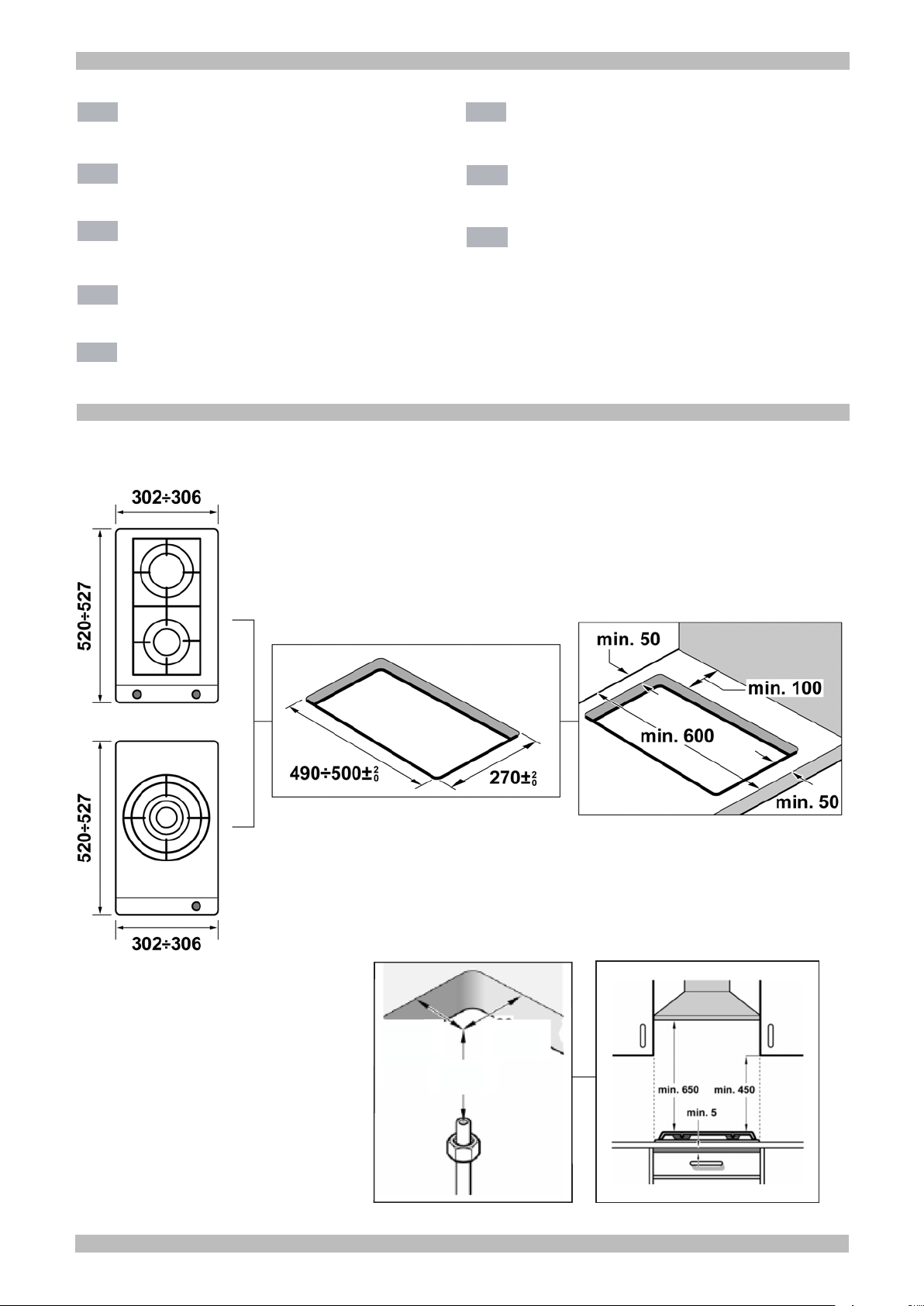
If an extractor fan is installed, you must
follow the installation manual's
instructions, always keeping a minimum
distance of 650 mm to the hob.
Preparation of kitchen unit
(fig. 1-2)
Make an appropriate size cut in the work
surface.
If the hob is electric or mixed (gas and
electricity) and there is no oven below,
place a non-flammable separator (e.g.
metal or plywood) 10 mm from the
bottom of the hob. This will prevent
access to the base of the hob.
If the hob is gas, it is recommendable to
place the separator at the same
distance.
On wood work surfaces, varnish the
cutting surfaces with a special glue. This
protects them from moisture which could
collect under the work surface.
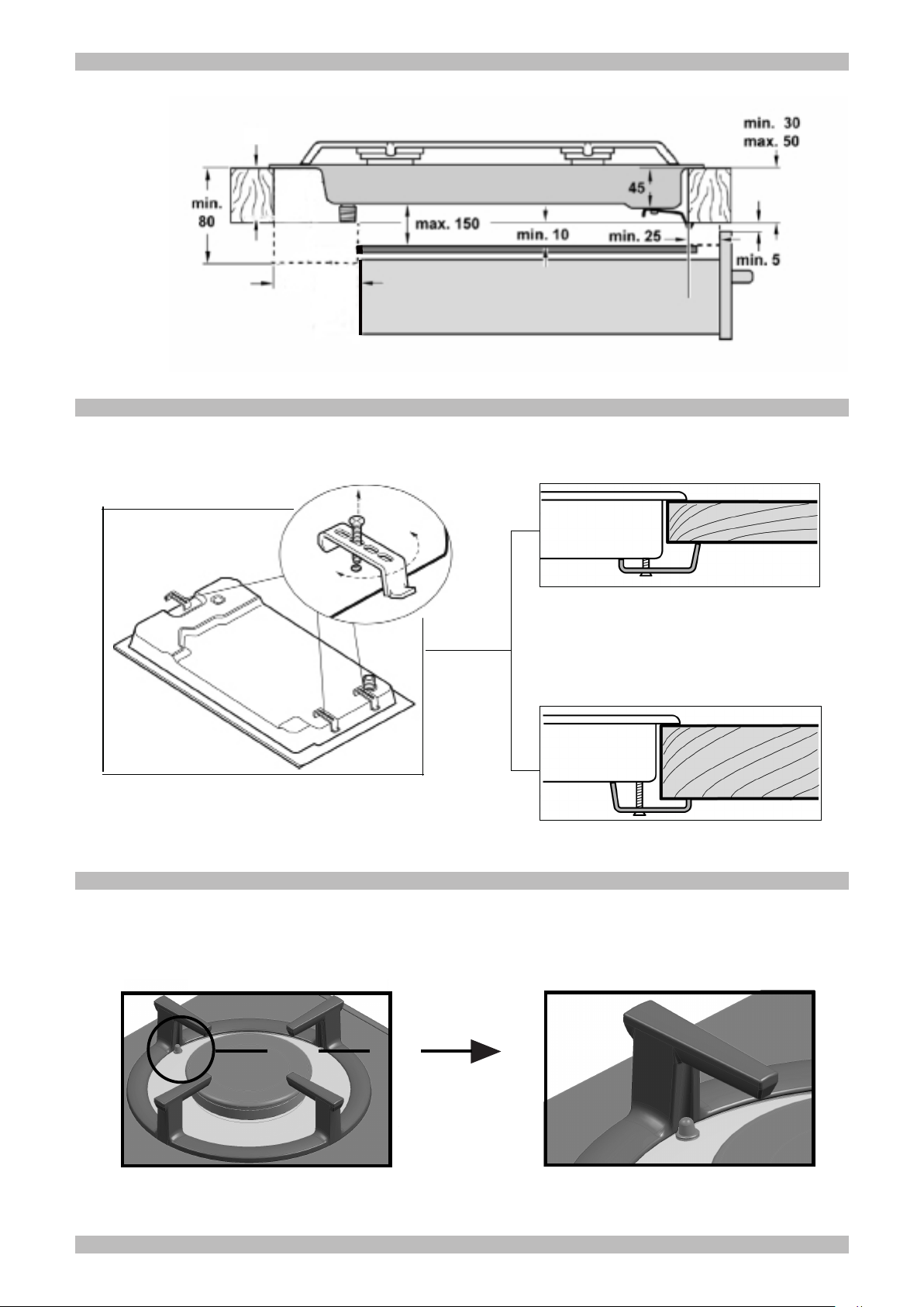
Installation of appliance
The clips and the adhesive seal
(underside of the hob) are factory-fitted:
do not under any circumstances remove
them. The seal ensures that the entire
work surface will be watertight, and
prevents water seepage.
In order to fit the appliance into the
kitchen unit, first place the hob in the
correct position then loosen each of the
clips so that they all turn freely (it is not
necessary to completely undo them).
Insert and centre the hob.
Press the sides of the hob until it is
supported around its entire perimeter.
Turn the clips and tighten them fully.
Fig. 3.
In order to complete the installation
process, you must place the diffusers
and the tops of the burners on their
corresponding burners. Also you must
place the grids correctly on their
supporting elements. Fig. 4.
Removal of hob
Turn off the appliance's electricity and
gas supply.
Unscrew the clips and proceed in the
reverse order to installation.
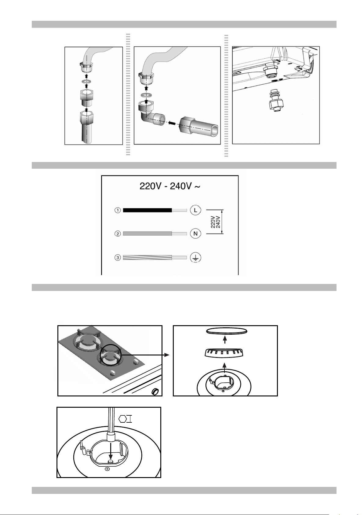
Gas connection (fig. 5)
The end of the inlet connection point of
the gas hob has a 1/2” (20.955 mm)
thread that allows for:
- fixed connection.
- connection using a flexible metal pipe
(L min. 1 m - max. 3 m). In this case, it is
necessary to insert the accessory
(427950) and the watertight seal
(034308) supplied between the manifold
outlet and the gas supply. Fig. 5a.
In this case, you must prevent the pipe
from coming into contact with moving
parts of the kitchen unit being inserted
(for example, a drawer) and prevent
access to any spaces which might
become obstructed.
If you need to connect the gas supply
horizontally, our Technical Assistance
Service can supply you with an L-tube
(code 173018) and a seal (code
034308).
To be able to use this appliance in
France, it is necessary to carry out a
direct connection to the outlet of the
connection point with the seal 034308.
Fig. 5b.
Warning! If any connection is handled,
check the seal.
Danger of leaks.
The manufacturer is not liable for any
connection leaking, after being handled.
Electric connection (fig. 6)
Check that the voltage and power of the
appliance are compatible with the
electrical installation.
The hobs are supplied with a power
cable with or without a wall socket plug.
Provide an omnipolar cut-off switch with
a minimum contact separation of 3 mm
(except for plug connections, if the user
has access to it).
Appliances with plugs must only be
connected to sockets that have earth
wires correctly installed.
This appliance is type “Y”: the supply
cable can only be changed by the
Technical Assistance Service and not
the user. The cable type and minimum
cross-section must be respected.
Changing the gas type
If the country's regulations allow, this
appliance can be adapted to other types
of gas (see specifications plate). The
components required for this are in the
transformation kit supplied (depending
on the model) available from our
Technical Assistance Service. The
following steps should be taken:
A) Change the nozzles of the burners
on the cooking hob:
- Remove the pan supports, covers and
the main body of the burner, Fig 7.
- Change the burner tips using a 7 mm
socket spanner and make sure that they
are tightened all the way in order to
ensure that they are correctly sealed
(see table II). With these burners the air
does not have to be adjusted.
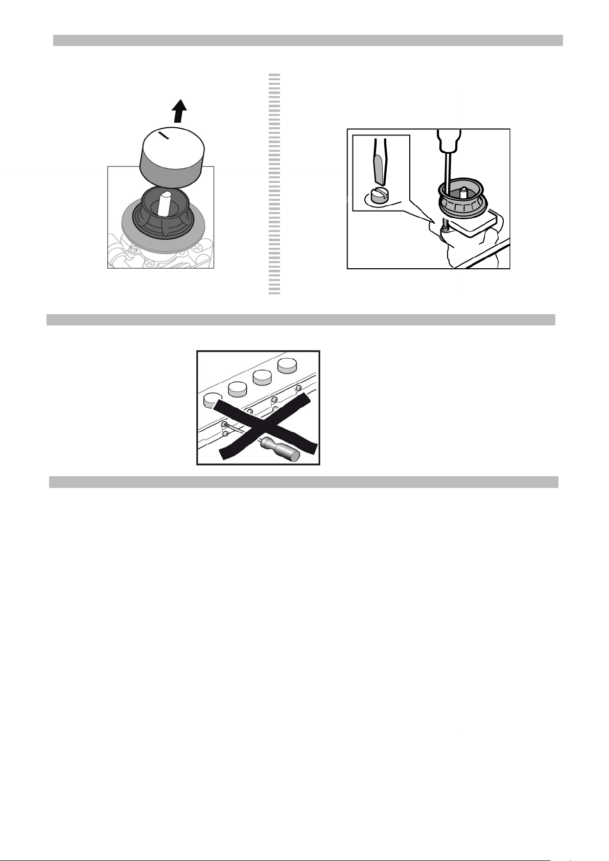
Adjustment of the taps
Set the control knobs to minimum.
Remove the control knobs from the taps.
Fig. 8
It has a flexible rubber valve reinforcing
ring. Simply press on this seal with the
tip of a screwdriver to allow access to
the tap adjusting screw. Fig. 8a.
Never remove the valve reinforcing
ring.
If the by-pass screw cannot be
accessed, disassemble the glass panel
and frame described in: Changing the
nozzles for double-flame burners. Fig. 7.
Adjust the minimum ring setting by
turning the by-pass screw using a flat
head screwdriver.
Depending on the gas to which your
appliance is going to be adapted, see
table III, carry out the corresponding
action:
A: firmly tighten the by-pass screws.
B: loosen the by-pass screws until the
gas flow from the burners is correct:
when adjusting the control knob
between maximum and minimum, the
burner does not go out, nor is there a
flame backdraught created.
C: the by-pass screws need to be
changed by an authorised installation
engineer.
Page 6

D: do not touch the by-pass screws.
DE
de
It is important that all the seals are
refitted to form a seal.
These devices are essential for the
correct operation of the appliance as
they prevent liquids and dirt from
entering the appliance.
Refit the control knobs.
Never remove the tap spindle (fig. 9). In
the event of a malfunction, change the
whole tap.
Warning! After finishing, the sticker
indicating the new type of gas must
be placed close to the specifications
plate.
Lesen Sie die Gebrauchsanweisung für
das Gerät, bevor Sie es installieren und
benutzen.
Die Abbildungen in dieser Anleitung
dienen der Veranschaulichung.
Der Hersteller ist jeglicher
Verantwortung enthoben, wenn die
Bestimmungen dieses Handbuchs
nicht eingehalten werden.
Sicherheitshinweise zu
diesem Gerät
Alle Installations-, Regelungs- und
Umstellungsarbeiten auf eine andere
Gasart müssen von einem
autorisierten Fachmann und unter
Beachtung der jeweils anwendbaren
Regelungen und gesetzlichen
Vorgaben sowie der Vorschriften der
örtlichen Strom- und Gasversorger
vorgenommen werden.
Stellen Sie vor der Durchführung
jeglicher Arbeiten die Strom- und
Gaszufuhr ab.
Für Umstellungsarbeiten auf eine
andere Gasart empfehlen wir, den
Kundendienst zu rufen.
Dieses Gerät wurde ausschließlich für
die Verwendung in Privathaushalten
und nicht für die gewerbliche Nutzung
entworfen. Dieses Gerät darf nicht auf
Jachten oder in Wohnwagen eingebaut
werden.
Überprüfen Sie vor der Installation des
Geräts, dass die örtlichen
Voraussetzungen (Gasart und -druck)
und die Geräteeinstellungen
miteinander kompatibel sind (siehe
Tabelle I). Die Bedingungen für die
Geräteeinstellung finden Sie auf dem
Etikett oder Typenschild.
Dieses Gerät darf nur an einem
ausreichend belüfteten Ort und nur in
Übereinstimmung mit den für die
Belüftung geltenden Bestimmungen und
Richtlinien eingebaut werden. Das
Gerät darf nicht an einen Schornstein
oder eine Abgasanlage angeschlossen
werden.
Das Netzkabel muss am Einbaumöbel
gut befestigt werden, damit es nicht mit
heißen Teilen des Backofens oder des
Kochfeldes in Berührung kommen kann.
Elektrische Geräte müssen immer
geerdet werden.
Hantieren Sie nie im Inneren des
Gerätes. Rufen Sie gegebenenfalls
unseren Kundendienst an.
Vor dem Einbau
Dieses Gerät entspricht Klasse 3 gemäß
DIN EN 30-1-1 für Gasgeräte:
Einbaugeräte.
Diese Geräte sind untereinander und/
oder mit herkömmlichen Kochfeldern
derselben Marke kombinierbar, indem
ein Befestigungselement verwendet
wird.
Weitere Informationen finden Sie im
Katalog.
Die neben dem Gerät befindlichen
Möbel müssen aus nicht brennbaren
Materialien sein. Die Schichtwerkstoffe
der Möbel sowie der sie
zusammenhaltende Leim müssen
hitzebeständig sein.
Dieses Gerät darf nicht über
Kühlschränken, Waschmaschinen,
Spülmaschinen oder ähnlichen Geräten
eingebaut werden.
Wenn Sie das Kochfeld auf einem
Backofen installieren, muss dieser über
eine Zwangsbelüftung verfügen.
Überprüfen Sie die Abmessungen des
Backofens in Ihrem
Installationshandbuch.
Wenn eine Dunstabzugshaube
angebracht wird, muss dies gemäß der
Montageanleitung und immer unter
Berücksichtigung eines vertikalen
Mindestabstandes von 650 mm zum
Kochfeld geschehen.
Vorbereitung des
Küchenmöbels (Abb. 1-2)
Nehmen Sie in der Arbeitsfläche einen
Ausschnitt mit den benötigten
Abmessungen vor.
Wenn es sich bei dem Kochfeld um ein
elektrisches oder gemischtes Kochfeld
(Gas und elektrisch) handelt und sich
kein Ofen darunter befindet, bringen Sie
einen Zwischenboden aus nicht
brennbarem Material (z.B. Metall oder
Sperrholz) 10 mm unter dem Boden des
Kochfeldes an. So wird ein Zugang zum
unteren Teil des Kochfeldes verhindert.
Wenn es sich bei dem Kochfeld um ein
Gaskochfeld handelt, wird empfohlen,
den Zwischenboden im selben Abstand
zum Kochfeld anzubringen.
Bei Arbeitsflächen aus Holz firnissen Sie
die Schnittflächen mit Spezialleim, um
sie vor Feuchtigkeit zu schützen.
Einbau des Gerätes
Die Klammern und die Klebedichtung
(unterer Rand des Kochfelds) werden im
Werk montiert; unter keinen Umständen
entfernen. Die Dichtung gewährleistet
die Abdichtung der gesamten
Arbeitsfläche und verhindert das
Eindringen von Flüssigkeiten.
Zur Befestigung des Geräts im
Einbaumöbel muss, nachdem das
Kochfeld in seine Position gebracht
worden ist, jede einzelne dieser
Klammern soweit losgeschraubt
werden, dass sie sich frei drehen
können (es ist nicht notwendig, sie völlig
abzuschrauben).
Fügen Sie das Kochfeld mittig ein.
Drücken Sie die Ränder solange nach
unten, bis der gesamte Rand aufliegt.
Drehen Sie die Klammern und ziehen
Sie diese fest an. Abb. 3.
Zur Beendigung der Installation müssen
die Verteiler und die Brennerdeckel auf
den entsprechenden Kochstellen
angebracht werden. Zudem müssen die
Roste korrekt in deren Halteelemente
eingesetzt werden. Abb 4.
Ausbau des Kochfeldes
Trennen Sie das Gerät von der Stromund Gasversorgung.
Schrauben Sie die Klammern auf und
folgen Sie den Einbauschritten in
umgekehrter Reihenfolge.
Gasanschluss (Abb. 5)
Am Ende des Eingangsrohrs zum
Gaskochfeld befindet sich ein 1/2”
(20,955 mm) Gewinde. Dieses Gewinde
ermöglicht:
- einen Festanschluss.
- einen Anschluss mit einem flexiblen
Metallschlauch (L min. 1 m - max. 3 m).
In diesem Fall müssen das Zubehörteil
(427950) sowie die Dichtung (034308)
(beide mitgeliefert) zwischen dem
Auslass der Sammelleitung und dem
Gasanschluss angebracht werden. Abb.
5a.
In diesem Fall ist zu vermeiden, dass
dieser Schlauch in Kontakt zu den
beweglichen Teilen der Einbaueinheit
gelangt (z. B. mit einer Schublade), und
er darf nicht durch Öffnungen verlegt
werden, die verschlossen werden
könnten.
Wenn ein horizontaler Gasanschluss
hergestellt werden soll, liefert Ihnen
unser technischer Kundendienst einen
Winkel mit der Teilenummer 173018,
sowie eine Dichtung mit der
Teilenummer 034308.
Bei der Verwendung dieses Geräts in
Frankreich muss der Anschluss direkt
am Ausgang der Sammelleitung mit
Hilfe der mitgelieferten Dichtung 034308
erfolgen. Abb. 5b.
Hinweis! Nach Arbeiten an einer
Anschlussstelle, diese immer auf
Dichtheit prüfen.
Gasaustrittsgefahr!
Der Hersteller übernimmt für den
Gasaustritt an einer Anschlussstelle,
an der zuvor hantiert wurde, keine
Verantwortung.
Elektrischer Anschluss
(Abb. 6)
Prüfen Sie, ob Spannung und
Nennleistung des Geräts mit der
elektrischen Installation
übereinstimmen.
Die Kochfelder werden mit Netzkabel
mit oder ohne Stecker ausgeliefert.
Es muss ein allpoliger Trennschalter mit
mindestens 3 mm Kontaktabstand
angebracht werden (außer bei
Anschluss an eine frei zugängliche
Steckdose).
Mit Stecker ausgestattete Geräte dürfen
nur in vorschriftsmäßig angebrachte,
geerdete Steckdosen gesteckt werden.
Page 7

Das Gerät gehört zum Typ "Y": Das
fr
Zuleitungskabel darf nicht vom
Benutzer, sondern nur vom
Kundendienst ausgetauscht werden.
Sowohl Kabeltyp als auch minimaler
Querschnitt müssen berücksichtigt
werden.
Umstellung auf eine andere
Gasart
Wenn die einschlägigen Bestimmungen
des jeweiligen Landes dies erlauben,
kann dieses Gerät auf andere Gasarten
umgestellt werden (siehe Typenschild).
Die hierfür notwendigen Teile befinden
sich im mitgelieferten Umbaukit (je nach
Modell), das über den Kundendienst
bezogen werden kann. Es müssen
folgende Schritte befolgt werden:
A) Auswechseln der Brennerköpfe
des Kochfelds:
- Die Roste, Deckel und Brennerkörper
abnehmen. Abb. 7.
- Die Brennerköpfe mit einem 7 mm
Steckschlüssel auswechseln und fest
anziehen damit deren Dichtheit
gewährleistet ist (siehe Tabelle II).
Bei diesen Brennern muss keine
Einstellung der Primärluft vorgenommen
werden.
Einstellung der Gashähne
Drehen Sie die Bedienknebel auf die
minimale Position.
Ziehen Sie die Schalter der Gashähne
ab. Abb. 8.
Es wird ein innerer Dichtring aus
flexiblem Gummi sichtbar. Es ist
ausreichend, diese mit der
Schraubenzieherspitze beiseite zu
drücken, um an die Einstellschraube des
Gashahns zu gelangen. Abb. 8a.
Bauen Sie die Knebeldichtungen
niemals aus.
Stellen Sie die minimale Gaszufuhr ein,
indem Sie die Bypass-Schraube mit
einem Schlitzschraubenzieher drehen.
Je nach Gasart, auf die Sie umstellen ,
siehe Tabelle III, müssen
entsprechende Schritte durchgeführt
werden:
A: die Kleinbranddüsen ganz anziehen.
B: die Kleinbranddüsen bis zum
korrekten Gasaustritt an den Brennern
lockern:
stellen Sie sicher, dass bei einer
Umstellung des Bedienknebels von der
maximalen auf die minimale Position,
die Flamme nicht ausgeht und nicht
zurückschlägt.
C: die Kleinbranddüsen sollten von
einem autorisierten Fachmann
ausgetauscht werden.
D: die Kleinbranddüsen nicht
manipulieren.
Es ist wichtig, dass alle
Knebeldichtungen richtig angebracht
sind, um die Dichtheit zu gewährleisten.
Die Dichtungen sind für den fehlerfreien
Betrieb des Geräts unerlässlich, da sie
das Eindringen von Flüssigkeiten und
Schmutz ins Geräteinnere verhindern.
Stecken Sie die Bedienknebel
wieder auf.
Bauen Sie niemals die Achse des
Gashahns aus (Abb. 9). Bei einer
Störung sollte der komplette Gashahn
ersetzt werden.
Achtung! Bringen Sie den Aufkleber
mit der umgestellten Gasart in der
Nähe des Typenschildes an.
Lisez les instructions de l'appareil avant
de procéder à son installation et à son
utilisation.
Les graphiques représentés dans cette
Notice de montage sont purement à
caractère informatif.
Le fabricant est exempt de toute
responsabilité si les indications de ce
manuel ne sont pas respectées.
Indications de sécurité
Tous les travaux d'installation, de
réglage et d'adaptation à un autre
type de gaz doivent être réalisés par
un technicien habilité qui doit
respecter les normes et la législation
applicables, ainsi que les
prescriptions des sociétés locales
fournisseuses d'électricité et de gaz.
Avant toute action, coupez
l'alimentation électrique et de gaz de
l'appareil.
Il est recommandé d'appeler le
Service Technique pour l'adaptation
à un autre type de gaz.
Cet appareil est destiné uniquement à
un usage domestique non
professionnel. Cet appareil ne peut pas
être installé dans des yachts ou des
caravanes.
Avant l'installation, vous devez vérifier
que les conditions de distribution locale
(nature et pression du gaz) et le réglage
de l'appareil sont compatibles (voir
tableau I). Les conditions de réglage de
l'appareil sont inscrites sur l'étiquette ou
la plaque signalétique.
Cet appareil ne peut être installé que
dans un endroit bien ventilé, en
respectant les règlements en vigueur et
les dispositions relatives à la ventilation.
L'appareil ne doit pas être connecté à un
dispositif d'évacuation des produits de
combustion.
Le câble d'alimentation doit être fixé au
meuble pour qu'il ne touche pas des
parties chaudes du four ou de la plaque
de cuisson.
Les appareils alimentés électriquement
doivent être obligatoirement connectés
à la terre.
Ne manipulez pas l'intérieur de
l'appareil. Le cas échéant, appelez notre
Service Technique.
Avant l'installation
Cet appareil correspond à la classe 3,
selon la norme EN 30-1-1 pour les
appareils à gaz : appareil encastré dans
un meuble.
Ces appareils peuvent être combinés
entre eux, et/ou avec des plaques de
cuisson conventionnelles de la même
marque, en utilisant l'accessoire
d'union.
Consultez le catalogue.
Les meubles situés à proximité de
l'appareil doivent être fabriqués dans
des matériaux non inflammables. Les
revêtements stratifiés et la colle qui les
fixe doivent être résistants à la chaleur.
Cet appareil ne peut pas être installé sur
des réfrigérateurs, des machines à laver
le linge, des lave-vaisselle ou d'autres
appareils semblables.
Pour installer la table de cuisson sur un
four, celui-ci doit disposer d'une
ventilation forcée.
Vérifiez les dimensions du four dans le
manuel d'installation.
Si une hotte aspirante est installée, il
faut respecter les observations de son
manuel d'installation, et respecter
toujours une distance verticale minimum
de 650 mm par rapport à la plaque de
cuisson.
Préparation du meuble
(fig.1-2)
Effectuez une découpe sur la surface de
travail selon les dimensions
nécessaires.
Si la plaque de cuisson est électrique ou
mixte (gaz et électricité) et s'il n'y a pas
de four dessous, placez un séparateur
de matériau non inflammable (p. ex.
métal ou bois contreplaqué) à 10 mm de
la base de la plaque de cuisson. Ainsi
est empêché l'accès à la partie
inférieure de celle-ci.
Si la table de cuisson est à gaz, il est
recommandé de placer le séparateur à
la même distance.
Pour des surfaces de travail en bois,
vernissez les surfaces de découpe avec
une colle spéciale, pour les protéger de
l'humidité.
Installation de l'appareil
Les agrafes et le joint adhésif (bord
inférieur de la plaque de cuisson) sont
posées en usine et ne sont à retirer en
aucun cas. Le joint garantit l'étanchéité
de toute la surface de travail et évite les
infiltrations.
Pour fixer l’appareil au meuble
d’encastrement, après avoir placé le
plan de travail dans sa position de
travail, vous devrez dévisser chaque
agrafe jusqu’à ce qu’elle tourne
librement (il n’est pas nécessaire de
dévisser complètement).
Encastrez et centrez la plaque de
cuisson.
Appuyez sur ses extrémités jusqu'à ce
qu'elle s'appuie sur tout son périmètre.
Tournez les agrafes et serrez-les à fond.
Fig. 3.
Pour terminer l’installation, il faut placer
les diffuseurs et le clapet des brûleurs
sur leurs feux correspondants. En outre,
il faudra placer de manière appropriée
les grilles sur leurs éléments de fixation.
Fig. 4.
Démontage de la plaque de
cuisson
Débranchez l'appareil des prises de
courant électrique et du gaz.
Page 8

Dévissez les agrafes et procédez de
it
manière inverse para rapport au
montage.
Branchement de gaz (fig. 5)
L'extrémité du branchement d'entrée de
la plaque de cuisson à gaz est munie
d'un filet d'un demi pouce (20,955 mm),
qui permet :
- La connexion rigide.
- Le raccordement avec un tuyau flexible
métallique (L min. 1 m - max. 3 m).
Dans ce cas, il faut intercaler
l'accessoire (427950) et le joint
d'étanchéité (034308) fournis entre la
sortie du collecteur et le branchement du
gaz. Fig. 5a.
Dans ce cas, il faut éviter le contact de
ce tuyau avec des parties mobiles de
l'unité d'encastrement (par exemple un
tiroir) et le passage à travers des
espaces pouvant s'obstruer.
Si vous avez besoin d’effectuer un
branchement de gaz horizontal, notre
Service Technique dispose d’un coude,
référence 173018, plus un joint,
référence 034308.
Pour utiliser cet appareil en France, il
faut réaliser la connexion directement à
la sortie du collecteur en utilisant le joint
034308 fourni. Fig. 5b.
Attention ! Si vous manipulez un
branchement, vérifiez son étanchéité.
Risque de fuites !
Le fabricant ne pourra être tenu
responsable si un branchement
quelconque présente des fuites après
avoir été manipulé.
Branchement électrique
(fig. 6)
Vérifiez que la tension et la puissance
de l'appareil sont compatibles avec
l'installation électrique.
Les plaques de cuisson sont fournies
avec un câble d'alimentation avec ou
sans broche de fiche mâle.
Il faut installer un interrupteur de
coupure omnipolaire avec ouverture de
contact d'au moins 3 mm (sauf pour des
connexions à fiche mâle, si cette
dernière est accessible par l'utilisateur).
Les appareils munis d'une broche ne
peuvent être raccordés qu'à des boîtiers
de fiche mâle dûment installés.
Cet appareil est du type “Y” : le câble
d'entrée ne peut pas être remplacé par
l'utilisateur, mais par le Service
Technique. Le type de câble et la
section minimum doivent être respectés.
Changement du type de gaz
Si la réglementation du pays le permet,
cet appareil peut être adapté à d'autres
gaz (voir plaque signalétique). Les
pièces nécessaires pour cela se
trouvent dans la pochette de
transformation fournie (selon le modèle)
ou disponible auprès de notre Service
Technique. Les pas à suivre sont les
suivants :
A) Changement des injecteurs des
brûleurs de la table de cuisson:
- Retirez les grillles, les clapets et le
corps de brûleur. Fig. 7.
- Changez les injecteurs en utilisant une
clé fermée de 7 mm et assurez-vous de
les serrer à fond pour garantir
l’étanchéité (voir tableau II).
Il ne faut réaliser aucun réglage de l’air
primaire dans ces brûleurs.
Réglage des robinets
Placez les boutons de commande sur la
position minimum.
Retirez les commandes des robinets.
Fig. 8.
Vous trouverez alors une bague en
caoutchouc flexible. Il suffira d’appuyer
avec la pointe du tournevis pour libérer
le pas vers la vis de régulation du
robinet. Fig. 8a.
Ne démontez jamais la bague.
Si vous ne trouvez pas l'accès à la vis
by-pass, démontez l'ensemble plaque
en verre plus profilés comme décrit
dans : Changement d’injecteurs pour les
brûleurs double flamme. Fig. 7.
Réglez le feu minimum en tournant la vis
by-pass à l'aide d'un tournevis à pointe
plate.
En fonction du type de gaz auquel vous
adapterez votre appareil, voir tableau III,
réalisez l'action correspondante :
A : serrez les vis by-pass à fond.
B : desserrez les vis by-pass jusqu'à
obtenir la sortie correcte de gaz des
brûleurs :
vérifiez, en réglant le bouton de
commande entre le maximum et le
minimum, que le brûleur ne s'éteint pas
et qu'aucun retour de flamme n'est
généré.
C : les vis by-pass doivent être
changées par un technicien habilité.
D : ne manipulez pas les vis by-pass.
Il est important que toutes les bagues
soient à leur place pour garantir
l’étanchéité. Ces dispositifs sont
indispensables au fonctionnement
correct de l’appareil vu qu’ils empêchent
l’entrée de liquides et de saleté à
l’intérieur de l’appareil.
Replacez les boutons de commande.
Ne démontez jamais l’axe du robinet
(fig. 9). En cas d’incidence, changez
complètement le robinet.
Attention ! À la fin, placez l'étiquette
autocollante, en indiquant le nouveau
type de gaz, près de la plaque
signalétique.
Leggere attentamente le istruzioni
dell'apparecchio prima di procedere
all'installazione e all'uso.
Le immagini presenti in queste Istruzioni
di Montaggio sono indicative.
Il fabbricante declina qualsiasi
responsabilità in caso di mancata
osservanza delle disposizioni del
presente manuale.
Indicazioni di sicurezza
Tutte le operazioni di installazione,
regolazione e adattamento a un
diverso tipo di gas devono essere
effettuate da un tecnico autorizzato,
nel rispetto della normativa e della
legislazione applicabili, nonché delle
prescrizioni delle società locali di
fornitura di gas ed elettricità.
Prima di effettuare qualsiasi
operazione, staccare l'alimentazione
elettrica e chiudere il gas
dell'apparecchio.
Per l'adattamento a un diverso tipo di
gas, si consiglia di rivolgersi al
Servizio Tecnico.
Questo apparecchio è stato concepito
per un esclusivo utilizzo domestico e
non professionale. Questo apparecchio
non può essere installato in yacht o
camper.
Prima dell'installazione, verificare che le
condizioni di distribuzione locale (tipo e
pressione del gas) e la regolazione
dell'apparecchio siano compatibili
(consultare la tabella I). Le condizioni di
regolazione dell'apparecchio sono
riportate sull'etichetta o sulla targa di
identificazione.
Questo apparecchio può essere
installato solo in un luogo ben ventilato,
nel rispetto dei regolamenti in vigore e
delle disposizioni relative alla
ventilazione. L'apparecchio non deve
essere collegato a un dispositivo di
espulsione dei prodotti di combustione.
Il cavo di alimentazione deve essere
fissato al mobile per evitare che tocchi
parti calde del forno o del piano di
cottura.
Gli apparecchi con alimentazione
elettrica devono essere collegati
obbligatoriamente a terra.
Non manipolare l'interno
dell'apparecchio. Ove necessario,
contattare il nostro Servizio Tecnico.
Prima dell'installazione
Questo apparecchio rientra nella classe
3 della norma EN 30-1-1 per gli
apparecchi a gas: apparecchio
incassato in un mobile.
Utilizzando l'accessorio di unione, questi
apparecchi possono essere combinati
tra loro e/o con piani di cottura
convenzionali della stessa marca.
Consultare il catalogo.
I mobili vicini all'apparecchio devono
essere costituiti da materiali non
infiammabili. I rivestimenti stratificati e la
colla con cui sono fissati devono essere
resistenti al calore.
Questo apparecchio non può essere
installato su frigoriferi, lavatrici,
lavastoviglie o elettrodomestici simili.
Per installare il piano di cottura su un
forno, verificare che quest'ultimo sia
dotato di ventilazione forzata.
Verificare le dimensioni del forno nel
relativo manuale di installazione.
Se si installa un estrattore, far
riferimento al relativo manuale di
installazione, mantenendo sempre una
distanza verticale minima di 650 mm dal
piano di cottura.
Preparazione del mobile
(fig. 1-2)
Effettuare un taglio, delle dimensioni
necessarie, sul piano di lavoro.
Se il piano di cottura è elettrica o mista
(gas ed elettricità) e non c'è un forno
Page 9

nella zona sottostante, collocare un
es
separatore di materiale non
infiammabile (ad es. metallo o legno
compensato) a 10 mm dalla base del
piano. In tal modo, se ne impedisce
l'accesso alla parte inferiore.
Se il piano di cottura è a gas, si
raccomanda di collocare il separatore
alla stessa distanza.
Sui piani di lavoro in legno, rifinire le
superfici di taglio con una colla speciale,
per proteggerle dall'umidità.
Installazione
dell'apparecchio
Le graffe e la guarnizione adesiva
(bordo inferiore del piano di cottura)
vengono applicate in fabbrica. Non
rimuoverle per nessun motivo. La
guarnizione garantisce
l'impermeabilizzazione di tutta la
superficie di lavoro ed evita qualsiasi
infiltrazione.
Per fissare l'apparecchio al mobile di
incasso, una volta collocato il piano
cottura nella sua posizione di lavoro,
occorre svitare le graffe una ad una fino
a che girino liberamente (non occorre
svitarle completamente).
Incassare e centrare il piano di cottura.
Premere sui bordi fino ad appoggiare
perfettamente tutto il perimetro.
Girare le graffe e stringerle a fondo.
Fig. 3.
Per completare l’installazione è
necessario collocare i diffusori e il
coperchio dei bruciatori sui fornelli
corrispondenti. Si devono inoltre
posizionare adeguatamente le griglie sui
loro elementi di sostegno. Fig. 4.
Smontaggio del piano di
cottura
Scollegare l'apparecchio dalla presa
elettrica e dall'attacco del gas.
Svitare le graffe e seguire, in modo
inverso, la procedura di montaggio.
Attacco del gas (fig. 5)
L'estremità della connessione in
ingresso del piano di cottura a gas è
dotata di filettatura da 1/2” (20,955 mm),
che consente:
-Il raccordo rigido.
-L'attacco a un tubo flessibile metallico
(L min. 1 m - max. 3 m). In questo caso,
occorre intercalare l'accessorio
(427950) e la guarnizione di tenuta
(034308) forniti fra l'uscita del collettore
e il raccordo del gas. Fig. 5a.
In questo caso, bisogna evitare il
contatto di questo tubo con le parti
mobili dell'unità d'incasso (ad esempio,
un cassetto) e il passaggio attraverso
spazi che potrebbero ostruirsi.
Nel caso in cui occorra realizzare il
raccordo del gas in orizzontale, presso il
nostro servizio tecnico si possono
trovare un gomito, con il codice 173018,
ed un giunto con il codice 034308.
Per utilizzare questo apparecchio in
Francia occorre realizzare il
collegamento direttamente all’uscita del
collettore utilizzando la guarnizione
034308 fornita. Fig. 5b.
Attenzione! Se si manipola qualunque
tipo di raccordo, verificarne la tenuta.
Pericolo di perdite!
Il fabbricante declina ogni responsabilità
in caso di connessioni che presentino
fughe dopo la manipolazione delle
stesse.
Connessione elettrica
(vedi fig. 6).
Verificare che la tensione e la potenza
dell'apparecchio siano compatibili con
l'impianto elettrico.
Le piastre di cottura vengono fornite
dotate di cavo di alimentazione con o
senza spina.
Prevedere un sezionatore onnipolare
con apertura di contatto di almeno 3 mm
(tranne che per i collegamenti a spina,
se l'utente può accedervi).
Gli apparecchi muniti di spina devono
essere collegati soltanto a cassette con
presa di terra debitamente installata.
Questo apparecchio è del tipo “Y”: Il
cavo di ingresso non può essere
cambiato dall'utente ma solo dal
Servizio Tecnico. Occorre infatti
rispettare il tipo di cavo e la sezione
minima.
Cambio del tipo di gas
Se la normativa del paese lo consente,
questo apparecchio può essere adattato
ad altri tipi di gas (v. targa
d'identificazione). I componenti
necessari a questa operazione si
trovano nella busta di conversione in
dotazione (secondo il modello),
disponibile presso il nostro Servizio
Tecnico. Procedere come indicato di
seguito:
A) Sostituzione degli iniettori dei
bruciatori del piano cottura:
- Togliere le griglie, i coperchi e il corpo
del bruciatore Fig. 7.
- Sostituire gli iniettori usando una
chiave a tubo di 7 mm e stringerli a fondo
per garantime la tenuta (vedi tabella II).
In questi bruciatori non è necessario
effettuare la regolazione dell´aria
primaria.
Regolazione delle chiavi
Collocare le manopole nella posizione di
minimo.
Estrarre le manopole dalle chiavi. Fig. 8.
Si troverà un dispositivo in gomma
flessibile. È sufficiente fare pressione
con la punta del cacciavite per creare
spazio e accedere alla vite di
regolazione della chiave. Fig. 8a.
Non smontare mai la guarnizione.
Se non è possibile accedere alla vite di
by-pass, smontare il gruppo vetro/profili
descritto in: Sostituzione degli iniettori
per bruciatori a doppia fiamma. Fig. 7.
Regolare il fuoco minimo girando la vite
di by-pass con un cacciavite a punta
piatta.
A seconda del gas utilizzato
dall'apparecchio, vedi tabella III, agire di
conseguenza:
A: stringere a fondo le viti di bypass.
B: allentare le viti di bypass fino alla
corretta regolazione del gas in uscita dai
bruciatori:
verificare che regolando la manopola tra
il massimo e il minimo, il bruciatore non
si spenga, né si verifichino ritorni di
fiamma.
C: le viti di bypass devono essere
sostituite da un tecnico autorizzato.
D: non manipolare le viti di bypass.
È importante posizionare tutte le tenute
per garantire la tenuta.
Questi elementi sono indispensabili per
il corretto funzionamento
dell’apparecchio dato che impediscono
l’introduzione di liquidi e sporcizia
all’interno dell’apparecchio.
Ricollocare le manopole.
Non smontare mai l’asse della chiave
(fig. 9). In caso di guasto, cambiare la
manopola completa.
Attenzione! Al termine, applicare
l'etichetta adesiva indicante il nuovo
tipo di gas vicino alla targa di
identificazione.
Lea las instrucciones del aparato antes
de proceder a su instalación y uso.
Los gráficos representados en estas
instrucciones de montaje son
orientativos.
El fabricante queda exento de toda
responsabilidad si no se cumplen las
disposiciones de este manual.
Indicaciones de seguridad
Todos los trabajos de instalación,
regulación y adaptación a otro tipo de
gas deben ser realizados por un
técnico autorizado, respetando la
normativa y legislación aplicables, y
las prescripciones de las compañías
locales eléctricas y de gas.
Antes de cualquier actuación, corte la
alimentación eléctrica y de gas del
aparato.
Se recomienda llamar al Servicio
Técnico para la adaptación a otro tipo
de gas.
Este aparato ha sido diseñado sólo para
uso doméstico, no profesional. Este
aparato no puede ser instalado en yates
o caravanas.
Antes de la instalación, debe comprobar
que las condiciones de distribución local
(naturaleza y presión del gas) y el
reglaje del aparato son compatibles (ver
tabla I). Las condiciones de reglaje del
aparato están inscritas sobre la etiqueta
o la placa de características.
Este aparato sólo puede ser instalado
en un lugar bien ventilado, respetando
los reglamentos en vigor y las
disposiciones relativas a la ventilación.
No debe conectarse el aparato a un
dispositivo de evacuación de los
productos de combustión.
El cable de alimentación debe fijarse al
mueble para evitar que toque partes
calientes del horno o placa de cocción.
Los aparatos con alimentación eléctrica
deben conectarse a tierra
obligatoriamente.
No manipule el interior del aparato. Si es
preciso, llame a nuestro Servicio
Técnico.
Page 10

Antes de la instalación
pt
Este aparato corresponde a la clase 3,
según la norma EN 30-1-1 para
aparatos a gas: aparato encastrado en
un mueble.
Estos aparatos pueden ser combinados
entre sí, y/o con placas de cocción
convencionales de la misma marca,
utilizando el accesorio de unión.
Consulte catálogo.
Los muebles próximos al aparato deben
ser de materiales no inflamables. Los
revestimientos estratificados y la cola
que los fija, deben ser resistentes al
calor.
Este aparato no se puede instalar sobre
neveras, lavadoras, lavavajillas o
similares.
Para instalar la placa de cocción sobre
un horno, éste debe tener ventilación
forzada.
Compruebe las dimensiones del horno
en su manual de instalación.
Si se instala un extractor, debe tenerse
en cuenta su manual de instalación,
respetando siempre una distancia
vertical mínima de 650 mm a la placa de
cocción.
Preparación del mueble
(fig. 1-2)
Haga un corte de las dimensiones
necesarias en la superficie de trabajo.
Si la placa de cocción es eléctrica o
mixta (gas y electricidad) y no hay un
horno debajo, coloque un separador de
material no inflamable (p. ej. metal o
madera contrachapada) a 10 mm de la
base de la placa de cocción. Así impide
el acceso a la parte inferior de ésta.
Si la placa de cocción es de gas, se
recomienda colocar el separador a la
misma distancia.
En superficies de trabajo de madera,
barnice las superficies de corte con una
cola especial, para protegerlas de la
humedad.
Instalación del aparato
Las grapas y la junta adhesiva (borde
inferior de la placa de cocción) salen
puestas de fábrica, no quitar bajo ningún
concepto. La junta garantiza la
impermeabilización de toda la superficie
de trabajo y evita cualquier filtración.
Para la fijación del aparato al mueble de
encastramiento, deberá, una vez
colocada la encimera en su posición de
trabajo, desatornillar cada una de las
grapas hasta que éstas giren libremente
(no es necesario el desatornillado total).
Encastre y centre la placa de cocción.
Presione sobre sus extremos hasta que
se apoye en todo su perímetro.
Gire las grapas y apriételas a fondo.
Fig. 3.
Para finalizar la instalación, es
necesario que coloque los difusores y la
tapa de los quemadores en sus
correspondientes fuegos. Además
deberá colocar adecuadamente las
parrillas en sus elementos de sujección.
Fig 4.
Desmontaje de la placa de
cocción
Desconecte el aparato de las tomas
eléctrica y de gas.
Desatornille las grapas y proceda de
modo inverso al montaje.
Conexión de gas (fig. 5)
El extremo de la conexión de entrada de
la placa de cocción de gas está provisto
de una rosca de 1/2” (20,955 mm), que
permite:
- la conexión rígida.
- la conexión con un tubo flexible
metálico (L min. 1 m - max. 3 m). En
este caso es necesario intercalar el
accesorio (427950) y la junta de
estanquidad (034308) suministradas,
entre la salida del colector y la
acometida de gas. Fig. 5a.
En este caso hay que evitar el contacto
de este tubo con partes móviles de la
unidad de encastramiento (por ejemplo
un cajón) y el paso a través de espacios
que pudieran ser susceptibles de
obstruirse.
Si necesita realizar la conexión de gas
en horizontal, en nuestro servicio
técnico dispone de un codo con el
código 173018, más una junta con el
código 034308.
Para la utilización de este aparato en
Francia es necesario hacer la conexión
directamente a la salida del colector
utilizando la junta 034308 suministrada.
Fig. 5b.
¡Atención! Si manipula cualquier
conexión, compruebe la estanquidad.
¡Peligro de fuga!
El fabricante no se responsabiliza si
alguna conexión presenta fugas tras
haber sido manipulada.
Conexión eléctrica (fig. 6)
Compruebe que el voltaje y la potencia
del aparato son compatibles con la
instalación eléctrica.
Las placas de cocción se suministran
con un cable de alimentación con o sin
clavija de enchufe.
Debe preverse un interruptor de corte
omnipolar con abertura de contacto mín.
de 3 mm (excepto en conexiones con
enchufe, si éste es accesible para el
usuario).
Los aparatos provistos de clavija, sólo
se deben conectar a cajas de enchufe
con toma de tierra debidamente
instalada.
Este aparato es del tipo “Y”: el cable de
entrada no puede ser cambiado por el
usuario, sino por el Servicio Técnico. Se
deben respetar el tipo de cable y la
sección mínima.
Cambio del tipo de gas
Si la normativa del país lo permite, este
aparato se puede adaptar a otros gases
(ver placa de características). Las
piezas necesarias para ello están en la
bolsa de transformación suministrada
(según modelo) disponible en nuestro
Servicio Técnico. Los pasos a seguir
son los siguientes:
A) Cambio de inyectores de los
quemadores de la placa de cocción:
- Retire las parrillas, tapas de quemador
y difusores Fig. 7.
- Cambie los inyectores usando una
llave de tubo de 7 mm y asegúrese de
apretarlos a fondo para garantizar la
estanquidad (ver tabla II).
En estos quemadores no hay que
realizar reglaje del aire primario.
Reglaje de los grifos
Coloque los mandos en la posición de
mínimo.
Retire los mandos de los grifos. Fig. 8.
Se encontrará con un retén de goma
flexible. Bastará con que se presione
con la punta del destornillador para que
se libere el paso hacia el tornillo de
regulación del grifo. Fig. 8a.
Jamás desmonte el retén.
Si no encuentra el acceso al tornillo
bypass, desmonte el conjunto cristal
mas perfiles descrito en: Cambio de
inyectores para quemadores de doble
llama. Fig. 7.
Regule el fuego mínimo girando el
tornillo bypass mediante un
destornillador de punta plana.
Dependiendo del gas al que vaya a
adaptar su aparato, ver tabla III, realice
la acción correspondiente:
A: apretar los tornillos bypass a fondo.
B: aflojar los tornillos bypass hasta la
correcta salida de gas de los
quemadores:
compruebe que al ajustar el mando
entre el máximo y el mínimo, el
quemador no se apaga ni se crea
retroceso de llama.
C: los tornillos bypass deben ser
cambiados por un técnico autorizado.
D: no manipular los tornillos bypass.
Es importante que estén colocados
todos los retenes para poder asegurar
la estanquidad. Estos dispositivos son
imprescindibles para el correcto
funcionamiento del aparato ya que
impiden la entrada de líquidos y
suciedad al interior del aparato.
Vuelva a colocar los mandos.
Nunca desmonte el eje del grifo (fig. 9).
En caso de avería, cambie el grifo
completo.
¡Atención! Al finalizar, coloque la
etiqueta adhesiva, indicando el
nuevo tipo de gas, cerca de la placa
de características.
Leia as instruções do aparelho antes de
proceder à sua instalação e uso.
Os gráficos são representados nestas
Instruções de montagem a título
orientativo.
O fabricante fica isento de toda a
responsabilidade caso não se
cumpram as disposições constantes
deste manual.
Indicações de segurança
Todos os trabalhos de instalação,
regulação e adaptação a outro tipo de
gás devem ser realizados por um
técnico autorizado, respeitando as
Page 11

regulamentações e legislação
aplicáveis, bem como o estipulado
pelas empresas locais de
electricidade e de gás.
Antes de qualquer procedimento,
corte a alimentação eléctrica e de gás
do aparelho.
Recomenda-se chamar o Serviço
Técnico para a adaptação a outro tipo
de gás.
Este aparelho foi unicamente concebido
para uso doméstico e não profissional.
Este aparelho não pode ser instalado
em iates nem em caravanas.
Antes da instalação deve comprovar se
as condições de distribuição local
(natureza e pressão do gás) e a
regulação do aparelho são compatíveis
(ver tabela I). As condições de
regulação do aparelho estão indicadas
na etiqueta ou na placa de
características.
Este aparelho só pode ser instalado
num local bem ventilado e cumprindo
com os regulamentos e as disposições
em vigor relativas à ventilação. Este
aparelho não deve ser ligado a um
equipamento extractor de produtos de
combustão.
O cabo de alimentação deve ser fixo ao
móvel para evitar que entre em contacto
com as partes quentes do forno ou da
placa de cozedura.
Os aparelhos com alimentação eléctrica
devem ser obrigatoriamente ligados à
terra.
Não manipule o interior do aparelho. Se
necessário, contacte o nosso Serviço de
Assistência Técnica.
Antes da instalação
Este aparelho corresponde à classe 3,
segundo a norma EN 30-1-1 para
aparelhos a gás: aparelho embutido
num móvel.
Estes aparelhos podem ser combinados
entre si e/ou com placas vitrocerâmicas
convencionais da mesma marca,
através da utilização do acessório de
união.
Consulte o catálogo.
Os móveis que fiquem próximos do
aparelho devem ser feitos de materiais
não inflamáveis. Os revestimentos
estratificados e a cola que os fixa devem
ser resistentes ao calor.
Este aparelho não pode ser instalado
sobre frigoríficos, máquinas de lavar
roupa, máquinas de lavar loiça ou
aparelhos similares.
Para instalar a placa de cozedura sobre
um forno, este deve incluir um
mecanismo de ventilação forçada.
Verifique as dimensões do forno no seu
manual de instalação.
Se instalar um extractor, deve ter em
conta o respectivo manual de
instalação, respeitando sempre uma
distância vertical mínima de 650 mm da
placa de cozedura.
Preparação do móvel
(fig. 1-2)
Realize um corte das dimensões
necessárias na superfície de trabalho.
Se a placa de cozedura for eléctrica ou
mista (gás e electricidade) e se não
houver um forno por baixo da mesma,
coloque um separador de material não
inflamável (por ex. de metal ou madeira
contraplacada) a 10 mm da base da
placa de cozedura. Assim impede o
acesso à parte inferior desta.
Se a placa de cozedura for a gás,
recomenda-se que coloque o separador
à mesma distância.
Em superfícies de trabalho de madeira,
envernize as superfícies de corte com
uma cola especial para as proteger da
humidade.
Instalação do aparelho
Os grampos e a junta adesiva (borda
inferior da placa de cozedura) vêm
instalados da fábrica e não devem ser
retirados em circunstância alguma. A
junta garante a impermeabilização de
toda a superfície de trabalho e evita
qualquer filtração.
Para a fixação do aparelho no móvel de
encastramento, deve, uma vez
colocada a bancada na respectiva
posição de trabalho, desaparafusar
cada um dos grampos até fazê-lo rodar
livremente (não sendo necessário
desaparafusar totalmente).
Encastre e centre a placa de cozedura.
Pressione sobre os seus extremos até
que se apoie em todo o seu perímetro.
Gire os grampos e aperte-os bem.
Fig. 3.
Para terminar a instalação, deve-se
colocar os difusores e a tampa dos
queimadores nos seus respectivos
lugares. Além disso, deve-se colocar
adequadamente as grelhas nos seus
elementos de fixação. Fig. 4.
Desmontagem da placa de
cozedura
Desligue o aparelho das tomadas
eléctricas e de gás.
Desaparafuse os grampos e proceda de
modo inverso ao da montagem.
Conexão de gás (fig. 5)
A extremidade do colector de entrada da
placa de cozedura a gás está equipada
com uma rosca de 1/2” (20,955 mm),
que permite:
- Realizar uma conexão rígida.
- Realizar a conexão com um tubo flexível
metálico (L min. 1 m - max. 3 m). Neste
caso, é necessário intercalar o acessório
(427950) e a junta de estanquicidade
(034308) fornecidos entre a saída do
colector e a entrada de gás. Fig. 5a.
Neste caso, deve-se evitar o contacto
deste tubo com qualquer parte móvel da
unidade onde se embutirá o aparelho
(por exemplo, uma gaveta), bem como a
sua passagem por onde pudesse ficar
obstrudo.
Para realizar a conexão de gás na
horizontal, o nosso serviço de
assistência técnica disponibiliza um
cotovelo (código 173018) e uma junta
(código 034308).
Para se utilizar este aparelho em
França, é necessário fazer a ligação
directamente à saída do colector,
utilizando a junta 034308 fornecida.
Fig. 5b.
Atenção! Se manipular qualquer
conexão, verifique a estanquicidade.
Perigo de fuga!
O fabricante não se responsabiliza se
alguma conexão apresentar fugas
depois de ter sido manipulada.
Conexão eléctrica (fig. 6).
Verifique se a voltagem e a potência do
aparelho são compatíveis com a
instalação eléctrica.
As placas de cozedura são fornecidas
com um cabo de alimentação com ou
sem ficha.
Deve-se prever um interruptor
omnipolar com uma abertura de
contacto mínima de 3 mm (excepto em
ligações com ficha se esta estiver
acessível ao utilizador).
Os aparelhos fornecidos com ficha só
devem ser ligados a tomadas de terra
devidamente instaladas.
Este aparelho é do tipo “Y”: o cabo de
entrada não pode ser mudado pelo
utilizador, só o Serviço Técnico deve
fazê-lo. Deve-se sempre respeitar a
secção mínima e o tipo de cabo.
Mudança do tipo de gás
Se as regulamentações do país o
permitirem, este aparelho pode ser
adaptado a outros tipos de gás (ver
placa de características). As peças
necessárias para tal estão incluídas na
bolsa de transformação fornecida
(consoante o modelo), também
disponível no nosso Serviço de
Assistência Técnica. Os passos a seguir
são os seguintes:
A) Substituição dos injectores dos
queimadores da placa de cozedura:
- Retire as grelhas, as tampas e corpo
do queimador Fig. 7.
- Substitua os injectores utilizando uma
chave tubular de 7 mm. Assegure-se de
que os injectores ficam bem apertados
para garantir uma total estanquicidade,
(ver tabela II).
Nestes queimadores não é necessário
realizar a regulação do ar primário.
Regulação das torneiras
Coloque os comandos na sua posição
mínima.
Retire os comandos das torneiras Fig. 8.
Inclui uma anilha de borracha flexível.
bastando pressioná-lo com a ponta da
chave de venda para que se libere o
acesso ao parafuso de regulação da
torneiro. Fig. 8a.
Nunca desmonte o retentor.
Se não encontrar o acesso ao parafuso
by-pass, desmonte o conjunto de
vidro + perfis descrito em: Mudança dos
injectores para os queimadores de
chama dupla. Fig. 7.
Regule a chama mínima rodando o
parafuso by-pass através de uma chave
de fendas de ponta plana.
Consoante o gás ao qual vai adaptar o
aparelho (ver tabela III), efectue a acção
correspondente:
A: apertar bem os parafusos bypass.
Page 12

B: afrouxar os parafusos bypass até
nl
conseguir a saída de gás correcta dos
queimadores:
verifique se, ao ajustar o comando entre
o máximo e o mínimo, o queimador não
se apaga nem ocorre um retrocesso da
chama.
C: os parafusos bypass devem ser
substituídos por um técnico autorizado.
D: não manipular os parafusos bypass.
É importante que todos os retentores
estejam colocados para se poder
assegurar a estanquicidade. Estes
dispositivos são imprescindíveis para o
correcto funcionamento do aparelho, já
que impedem a entrada de líquido e a
formação de sujidade no interior do
aparelho.
Volte a colocar os comandos.
Nunca desmonte o eixo da torneira
(fig. 9). Em caso de avaria, deve-se
substituir todo o conjunto que conforma
a torneira.
Atenção! Ao terminar, coloque a
etiqueta adesiva, indicando o novo
tipo de gás, próximo da placa de
características.
Lees de instructies van het apparaat
voor het overgaan tot de installatie en
het gebruik ervan.
De grafieken afgebeeld in dit
Installatievoorschrift zijn ter oriëntatie.
De fabrikant is vrij van elke
verantwoordelijkheid indien niet
voldaan wordt aan de beschikkingen
van deze handleiding.
Veiligheidsaanwijzingen
Alle werkzaamheden inzake
installatie, afstelling en aanpassing
aan een ander gastype moeten
uitgevoerd worden door een
geautoriseerde vakman, waarbij de
toepasbare normen en wetgeving
nageleefd moeten worden en ook de
voorschriften van de lokale
elektriciteits- en gasmaatschappijen.
Sluit, voor elke handeling de stroomen gastoevoer van het apparaat af.
Het wordt aanbevolen de Technische
Dienst te telefoneren voor de
aanpassing aan een ander type gas.
Dit apparaat is enkel ontworpen voor
huishoudelijk, niet professioneel
gebruik. Dit apparaat mag niet worden
geïnstalleerd in jachten of caravans.
Voor de installatie, moet u controleren
dat de voorwaarden van lokale
distributie (aard en druk van het gas) en
de afstelling van het apparaat
compatibel zijn (zie tabel I). De
afstelvoorwaarden van het apparaat
staan op het label of op het
gegevensplaatje.
Dit apparaat mag enkel worden
geïnstalleerd in een goed verluchte
ruimte, waarbij de geldende
reglementen en beschikkingen inzake
ventilatie nageleefd worden. Het
apparaat mag niet worden aangesloten
op een inrichting voor de afvoer van de
verbrandingsproducten.
De voedingskabel moet worden
vastgemaakt in het meubelstuk, om te
voorkomen dat deze contact maakt met
de gedeeltes van de oven of van de
kookplaat die warm worden.
De apparaten met stroomtoevoer
moeten verplicht geaard worden.
Manipuleer de binnenzijde van het
apparaat niet. Telefoneer, indien nodig
onze Technische Dienst.
Vóór de installatie
Dit apparaat behoort tot klasse 3,
volgens de norm EN 30-1-1 voor
gasapparaten: apparaat ingebouwd in
een meubel.
Deze apparaten kunnen onderling en/of
met conventionele kookplaten van
hetzelfde merk gecombineerd worden,
waarbij het verbindingsaccessoire moet
worden gebruikt.
Raadpleeg de catalogus.
De meubels dichtbij het apparaat
moeten uit niet ontvlambare materialen
bestaan. De gelaagde bekledingen en
de lijm die deze bevestigt, moeten
hittebestendig zijn.
Dit apparaat kan niet geïnstalleerd
worden op koelkasten, wasmachines,
vaatwassers of dergelijke.
Om een kookplaat op een oven te
installeren, moet deze over gedwongen
ventilatie beschikken.
Controleer de afmetingen van de oven in
uw installatiehandleiding.
Indien een afzuigkap geïnstalleerd
wordt, moet rekening gehouden worden
met de installatiehandleiding hiervan,
waarbij altijd een minimale verticale
afstand van 650 mm tot de kookplaat
behouden wordt.
Voorbereiding van het
meubel (afb. 1-2)
Breng een insnijding aan van de nodige
afmetingen op het werkvlak.
Indien de kookplaat elektrisch is of
gemengd (gas en elektriciteit) en er is
geen oven onder, plaats een
scheidingsstuk van niet-ontvlambaar
materiaal (bv. metaal of gelaagd hout)
op 10 mm van de basis van de
kookplaat. Zo wordt toegang vermeden
tot de onderzijde hiervan.
Indien het een gaskookplaat is, wordt
aanbevolen het scheidingsstuk op
dezelfde afstand te plaatsen.
Vernis voor houten werkvlakken de
snijvlakken met een speciale lijm, om
deze te beschermen tegen vocht.
Installatie van het apparaat
De klemmen en de zelfklevende pakking
(onderrand van de kookplaat) zijn in
productie geplaatst, verwijder deze
onder geen enkele voorwaarde. De
afdichting garandeert de waterdichtheid
van het hele werkoppervlak en voorkomt
infiltraties.
Voor de bevestiging van het apparaat
aan het inbouwmeubel moeten, na het
plaatsen van de kookplaat in de
werkstand, alle klemmen losgedraaid
worden tot deze vrij draaien (het volledig
losdraaien is niet nodig).
Bouw de kookplaat in en centreer.
Druk op de uiteinden hiervan tot deze
steunt op de hele omtrek.
Draai de klemmen en trek deze
helemaal aan. Afb. 3.
Om de aansluiting compleet te maken
moeten de pannenroosters en het
branderdeksel op de overeenkomstige
gaspitten worden geplaatst. Ook dienen
de roosters op de juiste wijze te worden
geplaatst. Afb 4.
Uitbouw van de kookplaat
Sluit het apparaat af van de
elektriciteitsen gasaansluiting.
Draai de klemmen los en ga op
omgekeerde werkwijze te werk als bij de
montage.
Gasaansluiting (afb. 5)
Het uiteinde van de inlaatcollector van
de gaskookplaat is voorzien van een
schroefdraad van 1/2” (20,955 mm). Met
deze schroefdraad is mogelijk:
-Een starre verbinding.
- een verbinding met een metalen slang
(L min. 1 m - max. 3 m). In dit geval
moeten het geleverde accessoire
(427950) en de afdichting (034308)
tussengevoegd worden, tussen de
uitlaat van de collector en de
gasaansluiting. Afb. 5a.
In dit geval moet worden vermeden dat
deze buis contact maakt met de
beweegbare onderdelen van de eenheid
waarin de kookplaat is ingebouwd (een
lade, bijvoorbeeld) of dat hij door ruimtes
loopt die verstopt kunnen raken.
Indien de gasaansluiting horizontaal
dient uitgevoerd te worden, zijn bij onze
service een kniestuk, met code 173018,
en een afdichting, met code 034308
verkrijgbaar.
Voor het gebruik van dit toestel in
Frankrijk, dient de aansluiting direct aan
de uitlaatpijp gemaak te worden, waarbij
de geleverde afdichting 034308 gebruik
wordt. Afb. 5b.
Opgelet! Indien een aansluiting
gemanipuleerd wordt, controleer de
lekdichtheid.
¡Lekgevaar!
De fabrikant neemt de
verantwoordelijkheid niet op zich indien
een aansluiting lekken vertoont, nadat
deze gemanipuleerd is.
Elektrische aansluiting
(afb. 6)
Controleer dat het voltage en het
vermogen van het apparaat compatibel
zijn met de elektrische installatie.
De kookplaten worden geleverd met een
voedingskabel met of zonder stekker.
Er moet een omnipolaire
onderbrekingsschakelaar voorzien
worden met een minimale
contactopening van 3 mm (behalve bij
stekeraansluiting, indien deze
gemakkelijk bereikbaar is voor de
gebruiker).
Apparaten die voorzien zijn van een
stekker mogen alleen op een goed
geaard stopcontact worden
aangesloten.
Dit apparaat is van het type “Y”: de
invoerkabel mag niet vervangen worden
Page 13

door de gebruiker, maar door de
tr
Technische Dienst. Het type kabel en de
minimumdoorsnede dienen te worden
gerespecteerd.
Verandering bij toepassing
van andere soorten gas
Indien de norm van het land het toelaat,
mag dit apparaat aangepast worden aan
andere gassen (zie gegevensplaatje).
De nodige delen hiertoe bevinden zich in
het geleverde omvormingspakket
(afhankelijk van het model). Het pakket
is beschikbaar in onze technische
dienst. Volg onderstaande stappen op:
A) Vervangen van de inspuiters van
de branders van de kookplaat:
- Haal de roosters, branderdeksels en
branderkelk eraf Afb. 7.
- Vervang de inspuiters met behulp van
een buissleutel van 7 mm. Draai deze,
om luchtdichtheid te garanderen,
helemaal vast, (zie tabel II).
In deze branders hoeft geen afstelling
voor primaire lucht plaats te vinden.
Afstelling van de kranen
Zet de knoppen in de laagste stand.
Haal de knoppen van de kranen af.
Afb. 8.
U treft een flexibele rubber keerring aan.
U dient enkel te drukken met de punt
van de schroevendraaier opdat de
doorvoer naar de stelschroef van de
kraan vrijkomt. Afb. 8a.
Bouw de afdichting nooit uit .
Indien u de toegang tot de bypass bout
niet vindt, bouw het geheel glas plus
profiel uit, beschreven in: Vervanging
van inspuiters voor branders met
dubbele vlam. Afb. 7.
Stel de minimumstand af door de
bypass bout te draaien met een
schroevendraaier met een vlakke punt.
Voer, afhankelijk van het gas waaraan
uw apparaat aangepast zal worden, zie
tabel III, onderstaande handeling uit:
A: trek de bypass bouten helemaal aan.
B: maak de bypass bouten los tot de
correcte gasuitlaat van de branders:
controleer dat bij het afstellen van de
knop tussen de maximum- en
minimumstand, de brander niet uitgaat
noch gasinslag gevormd wordt.
C: de bypass bouten moeten worden
vervangen door een geautoriseerde
vakman.
D: manipuleer de bypass bouten niet.
Het is belangrijk dat alle pakkingen
geplaatst zijn om de dichtheid te kunnen
verzekeren. Deze inrichtingen zijn
onmisbaar voor de correcte werking van
het apparaat, aangezien deze de inlaat
van vloeistof en vuil in het apparaat
vermijden.
Plaats de knoppen opnieuw.
Bouw de as van de kraan nooit uit
(afb. 9), bij storingen dient de kraan in
zijn geheel te worden vervangen.
Opgelet! Plaats ten slotte de sticker
die het nieuwe gastype aanduidt,
dichtbij het gegevensplaatje.
Cihazı kurmadan veya kullanmadan
önce talimatları okuyunuz.
Bu Montaj talimatlarında belirtilen
grafikler oryantasyon amaçlıdır.
Bu kılavuzdaki kurallara uyulmadığı
takdirde, üretici herhangi bir
sorumluluktan muaf olacaktır.
Güvenlik önerileri
Bütün kurulum, ayarlama ve gaz
tipine göre uyarlama işlemleri yetkili
bir teknisyen tarafından, ülkedeki
standartlara ve yürürlükteki kanuni
yönergeler ile yerel gaz ve elektrik
tedarikçisi şirketin talimatlarına
uygun olarak gerçekleştirilmelidir.
Herhangi bir işlemden önce, cihazın
gaz ve elektrik beslemesini kesiniz.
Diğer gaz tiplerine uyarlama
gerektiğinde Teknik Servisi
çağırmanız önerilir.
Bu cihaz, profesyonel kullanım için değil,
sadece ev kullanımı için tasarlanmıştır.
Bu cihaz yat veya karavanlara
kurulamaz.
Kurulumdan önce yerel dağıtım
koşullarını (gazın doğası ve basıncı)
öğreniniz ve cihaz ayarlarının uyumlu
olduğundan emin olunuz (bkz. tablo I).
Cihaz ayarlama koşulları etiket üzerinde
ya da özellikler tablosunda yazılı olarak
belirtilmiştir.
Bu cihaz sadece havalandırması iyi
yerlere, havalandı
yürürlükteki kurallara uygun olarak
kurulmalıdır. Cihaz, bir yanmış atık
boşaltım mekanizmasına
bağlanmamalıdır.
Elektrik kablosu, fırın veya pişirme
tezgahının sıcak kısımlarına temas
etmemesi için mutfak mobilyasına
sabitlenmelidir.
Elektrikle çalışan cihazların tüm
bağlantıları mutlaka topraklanmalıdır.
Cihazın iç kısmını kurcalamayınız.
Gerekirse Teknik Servisimizi çağırınız.
rma ile ilgili koşullar ve
Kurulumdan önce
Bu 3. sınıf cihaz, EN 30-1-1 gazlı
cihazlar normuna dayanmaktadır:
mobilyaya gömme cihaz.
Bu cihazlar kendi içlerinde ve/veya aynı
markaya ait geleneksel pişirme
tezgahları ile ek aksesuarlar kullanılarak
birleştirilebilir. Kataloğa bakınız.
Cihazın yakınındaki mobilyalar, yanıcı
olmayan malzemeden olmalıdır. Yüzey
kaplamaları ve bunları birbirine
yapıştıran tutkal, ısıya dayanıklı
olmalıdır.
Bu cihaz, buzdolabı, çamaşır makinesi,
bulaşık makinesi ve benzeri eşyaların
üzerine kurulamaz.
Pişirme tezgahını bir fırının üzerine
kurmak için, bu fı
havalandırmaya sahip olmalıdır.
Fırının boyutlarını, kurulum
kılavuzundan kontrol ediniz.
Havalandırma kurarken kurulum
kılavuzu dikkate alınmalı, her zaman
pişirme tezgahına en az 650 mm dikey
hiza alınmalıdır.
rın yapay bir
Mobilyanın hazırlanması
(şekil 1-2)
Çalışma yüzeyinin üzerine, belirtilen
ölçülerde bir kesik açınız.
Pişirme tezgahı elektrikli veya çoklu (gaz
ve elektrik) ise ve altında fırın
bulunmuyorsa, pişirme tezgahına 10
mm gelecek şekilde yanmaz
malzemeden yapılmış bir ayraç
yerleştiriniz (örneğin metal ya da ahşap
kontrplak). Böylece alt kısma giriş
engellenmiş olur.
Pişirme tezgahı gazlı ise, yine aynı
mesafede bir
Ahşap çalışma tezgâhlarında, yüzey
nemden korunmak amacıyla özel bir
kola ile verniklenir.
ayraç yerleştiriniz.
Cihazın kurulumu
Modele bağlı olarak kıskaçlar ve
yapışkan conta (pişirme tezgahının alt
kısmında) fabrikada monte edilmiştir;
hiçbir surette bulundukları yerden
çıkartmayınız. Conta, tüm çalışma
yüzeyinin su geçirmezliğini garanti eder
ve herhangi bir sızıntıyı önler.
Cihazı ankastre mobilyaya bağlamak
için, öncelikle ocağı doğru pozisyona
yerleştiriniz sonra, rahatça
dönebilmeleri için tüm kıskaçlarını
gevşetiniz (hepsini tamamen açmak
gerekli değildir).
Yerleştiriniz ve pişirme tezgahını
ortalayınız.
Yüzeyin tüm çevresini destekleyene
kadar kenarlarından bastırınız.
Kıskaçları döndürünüz ve sıkıca
vidalayınız. Şekil 3.
Kurulumu bitirmek için difüsörleri ve
brülör kapaklarını kendi yerlerine
yerleştirmeniz gerekmektedir. Bunun
yanı sıra ızgaraları doğru biçimde
yuvalarına yerleştirmelisiniz. Şekil 4.
Pişirme tezgahının
sökülmesi
Cihazın elektrik ve gaz alıcılarını
kapatınız.
Kıskaçları çıkarınız ve montajın tersi bir
sırayla devam ediniz.
Gazlı bağlantı (şek. 5)
- Gazlı pişirme tezgahı giriş
bağlantısının ucu 1/2" (20,955 mm)'lik
bir yivli dirsek ile donatılmıştır, bu şunları
sağlar:
- Sabit bağlantı.
- Bağlantının elastik bir boru ile
gerçekleştirilmesi (L min. 1 m - max. 3 m).
Gerekli olduğu durumlarda doğal gaz
dönüşümü için kolektör çıkışı ile gaz girişi
arasına verilen ara contayı 427950 ve
sızdırmazlık contasını (034308) takınız.
Şekil 5a.
Bu durumda hortumun, ankastre
biriminin hareketli parçaları (örneğin bir
çekmece) ile temas etmesine ve
tıkanmasına yol açabilecek olan
yerlerden geçişinin önlenmesi gereklidir.
Gaz ba
ğlantınızı yatay olarak
bağlamanız gerekirse Teknik Servisimiz
size bir dirsek (kodu 173018) ve bir
sızdırmazlık elemanı (kodu 034308)
sağlayabilir.
Page 14

Bu cihazın Fransa'da kullanımı için,
bağlantının doğrudan kolektör
üzerinden dönüşüm kitinde verilen
034308 conta ile yapılması gereklidir.
Şekil 5b.
Dikkat! Herhangi bir bağlantı
değiştirilecek olduğunda sızdırma yapıp
yapmadığını kontrol ediniz.
Sızıntı tehlikesi!
Herhangi bir gaz bağlantısı kurcalanma
sonucu sızıntı yaptığı takdirde üretici
firma sorumluluk kabul etmez.
Elektrikli bağlantı (şekil. 6)
Cihazın kuvvet ve voltajının elektrikli
kurulum için uygun olup olmadığını
kontrol ediniz.
Pişirme tezgahları, fişli veya fişsiz bir
besleme kablosu ile birlikte tedarik edilir.
Minimum kontak açıklığı 3mm olan bir
omnipolar akım kesici temin edilmelidir
(prizli bağlantılar hariç, eğer kullanıcı
tarafından erişilebiliyorsa).
Fişleri olan cihazlar, sadece uygun
şekilde yerleştirilmiş topraklama girişli
prizlere bağlanmalıdır.
Bu cihaz “Y” tipindendir: Giriş kablosu,
kullanıcı tarafından, Teknik Servis
olmadan değiştirilemez. Kablo tipine ve
minimum kalınlığa dikkat etmek
gerekmektedir.
Gaz tipinin değiştirilmesi
Ülke standartları izin verdiği takdirde,
cihaz farklı gaz tiplerine uyarlanabilir
(özellikler tablosuna bakınız). Bunun için
gerekli olan parçalar, Teknik
Servisimizden temin edilebilen
transformasyon donanım çantasında
bulunmaktadır (modele göre). İzlenecek
adımlar şu şekildedir:
A) Pişirme plakasinin brülör
enjektörlerinin değiştirilmesi:
- Izgaraları, brülör kapaklarını ve
gövdesini çıkartınız, şekil. 7.
- 7 mm’ lik bir boru anahtarı kullanarak
enjektörleri değiştiriniz ve sızdırmazlığı
garanti etmek için bunlar sonuna kadar
sıkış tırmış olduğunuzdan emin olunuz,
bkz. tablo II.
Bu brülörlerde, primer hava ayarını
gerçekleştirmeye gerek yoktur.
Vanaların ayarlanması
Kumanda düğmelerini minimum
konumuna getiriniz.
- Vanaların kumanda düğmelerini
çıkartınız. Şekil 8.
Esnek bir kauçuk conta ile işlem. Bu
contaya bir tornavidanın ucu ile basarak
ayar vanasına giden yolu açınız.
Şekil 8a.
Contayı asla sökmeyiniz.
By-pass vidasına erişim bulunmuyorsa
şu kısımda açıklanan cam profilleri
demonte ediniz: Çift alevli brülör
uçlarının değiştirilmesi. Şekil 7.
Düz uçlu tornavida ile by-pass vidasını
çevirerek en düşük alevi ayarlayınız.
Cihazınızın bağlanacağı gaz tipine göre,
bkz. tablo III, ilgili ayarları
gerçekleştiriniz:
A: bypass vidalarını iyice sıkış
B: bypass vidalarını brülörlerin doğru
gaz çıkışlarına kadar sıkıştırınız:
tırınız.
maksimum ve minimum arasındaki
kumanda düğmesini ayarlarken brülörün
sönmediğine ve alevin geri tepmediğine
emin olunuz.
C: bypass vidaları Teknik Servisimiz
tarafından değiştirilmelidir.
D: bypass vidalarına müdahale
etmeyiniz.
Sızdırma olmadığından emin olmak için
tüm contaların takılı olması
gerekmektedir. Bu gereçler, cihazın
doğru çalışması ve içerisine sıvı ya da
kirin girmemesi açısından önemlidir.
Kumanda düğmelerini yeniden
yerleştiriniz.
Vana milini asla sökmeyiniz (Şekil 9).
Arıza halinde vanayı komple değiştiriniz.
Dikkat! Son olarak yeni gaz tipini
gösteren etiketi özellikler tabelasının
yanına yapıştırınız.
Page 15

)
)
)
)
I
WV~ Hz
/h
G31
/h
G30
G25
m3/h
G20
m3/h
Qn (kW)
G30, G31
Qn (kW)
G20, G25
ES326AB20E HSE-C3FW130 3,60 3,60 0,343 0,399 261 257 0,8 W 220-240 V~ 50/60 Hz
ES326BB20E HSE-C3F2030 4,75 4,75 0,453 0,527 345 339 0,8 W 220-240 V~ 50/60 Hz
PSA326B20E HSE-C3FW130 3,60 3,60 0,343 0,399 261 257 0,8 W 220-240 V~ 50/60 Hz
PSB326B20E HSE-C3F2030 4,75 4,75 0,453 0,527 345 339 0,8 W 220-240 V~ 50/60 Hz
G-20/20 mbar ERDGAS / ERDGAS E /
NATURGAS / GAS NATURAL /
MAAKAASU NATURGAS / Φυοικ_αεοιο /
NATURAL GAS / GAS METANO / GAS
NATUREL / GAZ ZIEMNY
G-20/G-25-20/25 mbar AARDGAS / GAZ
NATUREL LACQ
2H
20
LV
I
2H3+
II
20-28/37
ES/GB/GR/IE
2H3+
IT/PT
II
20-30/37
DE
20-50
2E
20
LU
I
2ELL3B/P
II
2E+3+
BE/FR
II
20/25-28-30/37
20-30
2H3B/P
II
AT
2H3B/P
20-50
COUNTRIES/GASES GAS ADJUSTED MODEL TYPE
II
DK/FI/SE/CZ/SK/EE/LT/SI/RO/BG
Cat.
P(mbar)
Cat.
P(mbar)
Page 16

II
gas mbar Qn (kW) m3/h g/h Qr (kW)
G20 20 115 3 0,286 G25 20 132 3 0,333 G25 25 128 3 0,333 G30 29 85 3 - 218
G30 50 74 3 - 218
G31 37 85 3 - 214
G20 20 100 1,75 0,167 G25 20 100 1,75 0,194 G25 25 98 1,75 0,194 G30 29 67 1,75 - 127
G30 50 58 1,75 - 127
G31 37 67 1,75 - 125
G20 20 140 3,6 0,343 G25 20 150 3,6 0,399 G25 25 142 3,6 0,399 G30 29 97 3,6 - 261
G30 50 75 3,6 - 261
G31 37 97 3,6 - 257
39
39
39
39
33
39
30
30
30
30
26
30
53
53 1,26
53
53 1,26
42 1,26
53 1,26
0,50
0,50
0,50
0,60
0,60
0,60
0,35
0,35
0,29
0,41
0,41
0,41
1,26
1,26
III
G20/20 G25/20 G25/25 G30/29 G30/50 G31/37
G20/20
G25/20
G25/25
G30/29
G30/50
G31/37
D D A C A
D
D
D
B
B B
C
C C C
B
D A C A
A C A
C D
B B D C
C
Cod. 9000346902 D
 Loading...