

Page 1
en
Assembly instructions
please keep
nl
Installatievoorschrift
s.v.p. bewaren
1
de
fr
it
es
Einbauanleitung
bitte aufbewahren
Instructions dassemlage
veuillez conserver
Istruzioni di montaggio
si prega di conservarle
Instrucciones de montaje
por favor, guardar
min.60
5
480
min.30
pt
tr
hu
5
Instruçoes de montagem
por favor, guardar
Montaj talimatlarý
lütfen saklayýnýz
Beszerelési útmutató
kérjük, õrizze meg
min.30
5
1a
42,5
42,5
504,6
290
504,6
576
560
50
490
+2
- 0
+2
- 0
min. 600
min. 30
1152
1140
+2
- 0
1b
50
+2
490
- 0
min. 600
42,5
min. 30
504,6
864
45
43
650
min.50
+
490
1
600
+2
- 0
850
50
+2
- 0
490
min. 600
min. 30
268
1
+
Page 2
2a 2b
c 2d
2
3
4
5
4
a
4b
Page 3
6
7
7 mm.
8
9
Page 4

Page 5
Put these instructions in a safe place for future reference
Instructions for
the installation technician
All installation, regulation and adaptation to
other types of gas must be carried out by an
authorised installation technician,
respecting all applicable regulations,
standards and the country's electrical and
gas supply companies' specifications.
It is recommended that you call our
Technical Assistance Service for adaptation
to other types of gas. Before you begin, turn
off the appliance's electricity and gas supply.
Before connecting up the appliance to the
installation, first check that it has been adjusted
for the type of gas with which it is to be supplied
(see table I).
Our cooking hobs leave the factory designed to
function with the type of gas that is indicated on
the specifications plate.
It is of the utmost importance that the place
in which the appliance is installed has suitable
ventilation in accordance with regulations
so that the combustion gases are piped outside.
Check the dimensions of the cooking hob
as well as the dimensions of the hole to be cut
in the kitchen unit.
The panels located above the work surface,
right next to the cooking hob, must be made of
non-inflammable material. Both the stratified
surfacing and the glue used to secure it should
be heat resistant, to prevent deterioration.
No electrical cables should come into contact
with hot areas.
The power cable must be secured to the
furniture module to prevent it from touching any
hot parts of the oven or the cooking hob.
All appliances containing any electrical
components must be earthed.
Handle the appliance with care during the
entire installation process. Do not hit the
appliance against anything.
IN THE EVENT THAT THIS ADVICE IS
NOT FOLLOWED, THE INSTALLATION
TECHNICIAN WILL BE RESPONSIBLE FOR
ANY DAMAGE CAUSED, AND THE
MANUFACTURER WILL BE EXEMPT FROM
ALL RESPONSIBILITY.
Installing the cooking hob
in the furniture module
The option of locating the cooking hob in a kitchen
unit (in accordance with gas appliances regulation
EN 30-1-1) is Type 3.
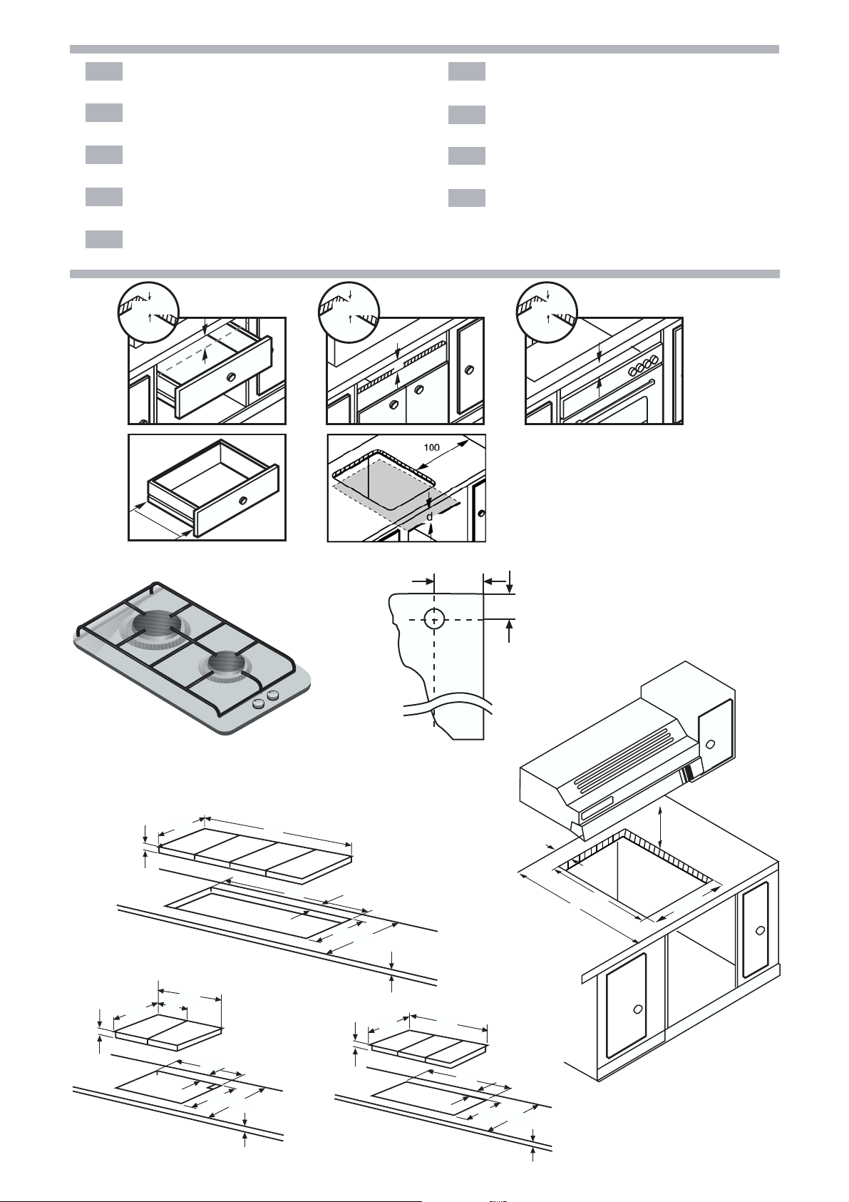
Fitting measurements
1 - Minimum distances (mm). Cut an aperture
of the necessary dimensions in the work surface.
Fig. 1.
In the event that no oven is to be installed
beneath the cooking hob, we recommend fitting
a separator which will block off access to the
underside of the cooking surface.
All gas d < 150
Electrical hob 10 < d < 150
If the cooking hob is to be installed above
an oven, check that the oven is fitted with power
ventilation, and check the dimensions according
to the assembly manual.
Place the cooking hob in the insertion
aperture cut into the furniture module.
2 - The wood fibres that have been used to
make the cooking hob modules tend to swell
quite quickly when they come into contact with
moisture. We therefore recommend that the cut
edges are treated with a special glue to protect
them from steam or any condensation that might
drip down beneath the work surface of the
cooker unit.
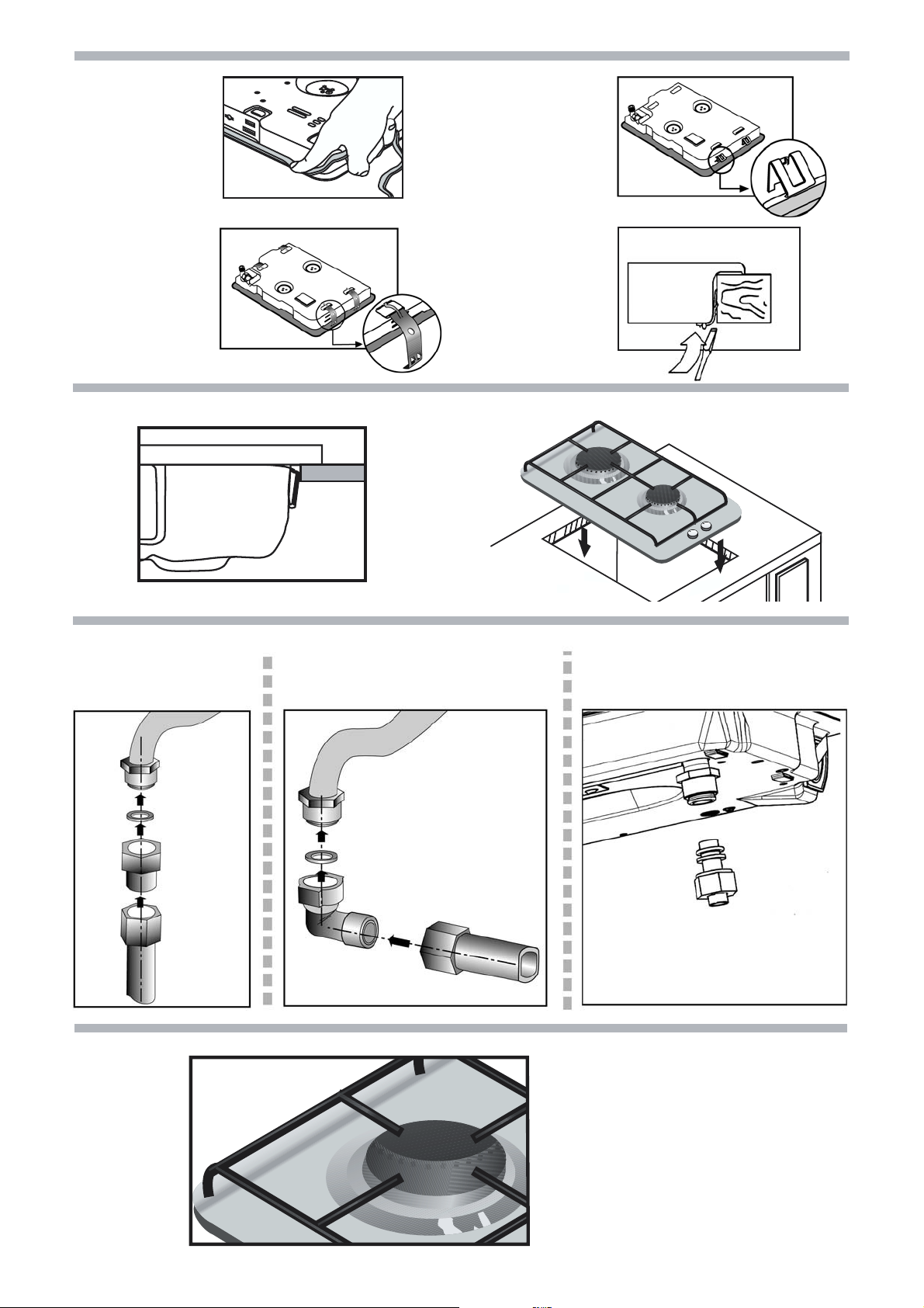
Depending on the model, the clips and the
watertight seal (underside of the cooking hob)
may already be fitted; if this is the case, do not
under any circumstance remove them. The seal
ensures that the entire work surface will be
watertight, and prevents water seepage. The
seal is to be placed on the edge of the interior
housing and should protrude approximately
3 mm.
If this item has not been fitted in the factory,
remove the pan supports and the gas burners
covers and diffusers from your cooking hob,
and turn it upside down. Now fit the adhesive
seal supplied with the appliance onto the lower
edge of the cooking hob (see Fig. 2a), remove
the staples from the attached accessories bag
and secure them into the lateral orifices that are
provided for this purpose. Fig. 2b or 2c.
3 - Press down all around the edges so that
the cooking hob is supported along its entire
perimeter (Fig. 3).
If you should need to dismantle the
appliance, simply push it upwards from
underneath (with staple type 2b).
If your cooking hob has the type of staple shown
in Fig. 2c, you will have to lever it up with a
screwdriver to dismantle it. Fig. 2d.
4 - On gas hobs, the end of the gas intake
comes with a
This thread ensures:
A rigid connection.
Connection using a flexible metal tube
(L min. 1m - max. 3m).
necessary to install the
9000060077 and seal (code
supplied or available through the
assistance service, between the outlet
1
(20,955 mm)
/ "
2
thread, Fig. 4.
In this case it is
accessory
034308),
technical
of the
manifold and the gas supply, Fig. 4a.
With this option, you must prevent the pipe from
coming into contact with moving parts of the
insertion unit (for example, a drawer) or access
to any spaces which might become obstructed.
If you need to connect the gas supply
horizontally, our technical services department
can supply you with an adaptor (code 173018)
and a seal (code 034308).
To be able to use this appliance in France, it is
necessary to carry out a direct connection to
the outlet of the manifold with the seal 034308.
Fig. 4b. The position of the gas pipe, relative to
the hole in the kitchen unit where it is to be fitted
is shown in Fig. 1b.
Make sure that all the connections that
have been installed are airtight.
The manufacturer declines any responsibility
for leaks or for any connections installed by
the installation technician.
5 - The following must be checked on the
specifications plate: the voltage and the total
power. This appliance must be earthed.
Always make certain that all connections
that have been installed are in accordance with
national legal requirements. Observe all the
requirements of the local electrical supply
company.
In order to meet standard safety regulations,
the installation technician must provide an
omnipolar cut-off switch with a contact separation
of at least 3 mm. This is not necessary if the
connection is made via a plug, so long as the
user has access to it.
All appliances fitted with plugs should only
be connected up to sockets which have been
correctly earthed.
This appliance is type "Y", which means that
the input cable MUST NOT BE CHANGED BY
THE USER, only by the service technician for
that particular make. The section and type of
cable must be observed.
en
Do not make any adjustments in the interior
of the appliance. If this should be necessary,
call our technical assistance service.
Our cooking hobs are provided with a power
cable with or without a plug.
Types of cables:
Power cable: cooking hob:
All gas 3 x 0.75 mm
Electrical hob 3 x 1.5 mm
6 - To complete the installation, the burner
diffusers and covers must be fitted onto their
corresponding rings. In addition, the pan supports
must also be located in their correct places.
Fig. 5. Modular hobs may be combined with the
appliance using the joint accessory NEZ34VLA.
Fig. 1a. If a ceramic hob is to be combined with
the appliance, the correct joint accessory to use
is NEZ34VLB; these are available from our
technical service.
Changing gas type
All installation, regulation and adaptation to
other types of gas must be carried out by an
authorised installation technician,
respecting all applicable regulations,
standards and the country's electrical and
gas supply companies' specifications.
It is recommended that you call our
Technical Assistance Service for adaptation
to other types of gas. Before you begin, turn
off the appliance's electricity and gas supply.
Provided that national laws so permit, this
cooking hob may be adapted to function with
other types of gas. To do so, all the following
steps should be carried out:
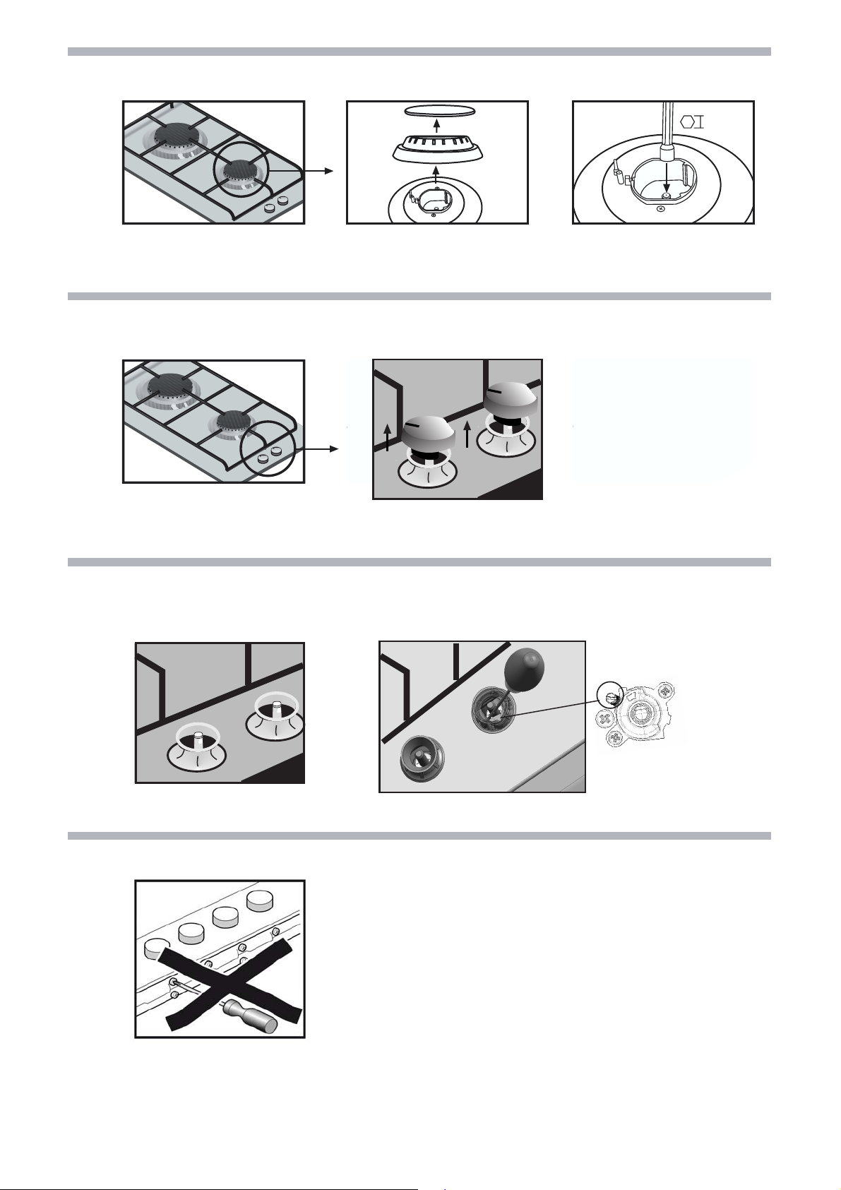
A) Change the nozzles of the burners on
the cooking hob.
1 - Remove the pan supports, covers and
the main body of the burner.
2 - Change the burner tips using a 7 mm
(see table II)
that they are
ensure that they
With these burners the air does not have to
be adjusted.
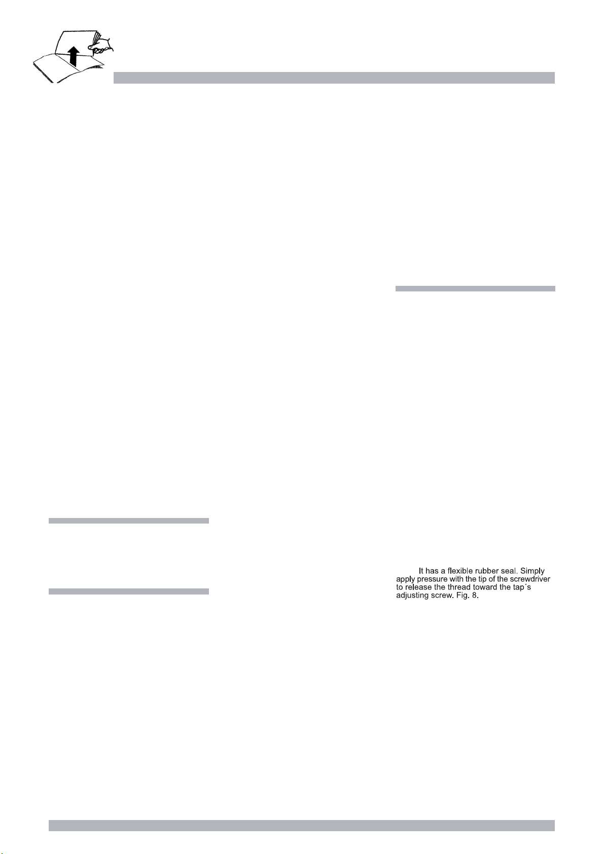
B) Adjust the burner taps for reduced
consumption.
1 - Turn the taps down to minimum.
2 - Remove the control knobs from the taps.
Fig. 7.
3 -
Do not remove the grip.
4 - Adjust the By-pass screw.
For propane and butane gas, the screw
must be screwed down tight.
For natural gas, turn the screw (to the left)
until the burner is producing the desired gas
flow, in such a way that when you turn the burner
controls from maximum to minimum, the flame
does not go out, nor is there a flame back
draught created
5 - It is important to make sure that all the
seals are in place in order to ensure that, in the
case of spillages on the hob, there are no short
circuits.
6 - Replace the control knobs on the taps.
Do not dismantle the tap shaft (Fig. 9):
In the
whole tap.
C) Place the sticker indicating that the
appliance's gas supply has been changed
next to the specifications plate.
socket spanner and make sure
tightened all the way in order to
are correctly sealed. Fig. 6.
.
event of a malfunction, change the
2
2
Page 6

Bitte gut aufbewahren
de
Anleitungen für
den Installateur
Alle Installations-, Regelungs- und
Umstellungsarbeiten auf eine andere Gasart
müssen von einem autorisierten Fachmann
und unter Beachtung der jeweils
anwendbaren Regelungen und gesetzlichen
Vorgaben sowie der Vorschriften der
örtlichen Strom- und Gasversorger
vorgenommen werden.
Für Umstellungsarbeiten auf eine andere
Gasart empfehlen wir, den Kundendienst zu
rufen.
Stellen Sie vor der Durchführung jeglicher
Arbeiten die Strom- und Gaszufuhr ab.
Vor dem Anschluss des Geräts an die
Installation muss überprüft werden, ob das Gerät
für den zugeleiteten Gastyp geeignet ist
Tabelle I).
Kochfelder sind werkseitig für den
Unsere
Betrieb mit
angegebenen Gasart
soll, muss vorschriftsmäßig belüftet sein.
Daher müssen die Verbrennungsgase ins Freie
ausgeleitet werden.
Abmessungen der im Möbel anzufertigenden
Öffnung überprüfen.
direkten Umgebung des Kochfelds müssen aus
nicht brennbarem Material bestehen. Sowohl
die Schichtwerkstoffe als auch der Bindeleim
müssen hitzebeständig sein, damit kein
Verschleiß auftritt.
Berührung zu den Hitzebereichen haben.
befestigt werden, damit sie nicht mit heißen
Teilen des Ofens oder des Kochfelds in
Berührung kommen kann.
vorschriftsgemäß mit der Erdableitung
verbunden werden.
behandeln. Keine Schläge auf das Gerät
ausführen.
BESTIMMUNGEN NICHT EINGEHALTEN,
LIEGT DIE HAFTUNG BEIM INSTALLATEUR
UND DER HERSTELLER IST VON DER
HAFTUNG AUSGENOMMEN.
der auf dem Typenschild
eingestellt.
Der Ort, an dem das Gerät installiert werden
Die Abmessungen des Kochfelds sowie die
Die Platten auf der Arbeitsfläche in der
Die elektrischen Leitungen dürfen keine
Die Stromnetzleitung muss am Möbel
Geräte mit elektrischen Bauteilen müssen
Das Gerät während der Installation vorsichtig
WERDEN DIE DIESBEZÜGLICHEN
(siehe
Einbau des Kochfelds im
Küchenmöbel
Die Einbaumöglichkeit des Kochfelds im
Küchenmöbel entspricht der Klasse 3 gemäß der
Norm für Gasgeräte EN 30-1-1.
Einbaumaßnahmen
1 - Mindestabstände (mm). In der Arbeitsplatte
einen Ausschnitt mit den erforderlichen
Abmessungen ausführen. Abb. 1.
Wenn unter der Arbeitsplatte kein Backofen
installiert wird, wird der Einbau eines
Trennelements empfohlen, damit der Zugang
von unten zum Kochfeld ausgeschlossen ist.
Nur Gas d < 150
Elektrische Kochplatte 10 < d < 150
Für die Installation über einem Backofen
muss geprüft werden, dass dieser über eine
Zwangsbelüftung verfügt. Ebenso müssen die
Abmessungen anhand der Einbauanleitung
überprüft werden.
Das Kochfeld in seiner Einbauöffnung im
Möbel zentrieren.
2 - Die Holzfasern, die zur Herstellung der
Arbeitsplattenmöbel verwendet werden, quellen
im Kontakt mit Feuchtigkeit relativ schnell auf.
Daher sollten die Schnittflächen mit einem
Spezialleim behandelt werden, um diese Flächen
vor Dampf und Kondenswasser, das sich unter
der Arbeitsplatte des Küchenmöbels bilden
könnte, zu schützen.
Je nach Modell sind die Klammern und
Dichtungen (Unterrand des Kochfeld) bereits
montiert. Diese dürfen dann keinesfalls
abgenommen werden. Die Dichtung
gewährleistet die Abdichtung der gesamten
Arbeitsfläche und verhindert das Eindringen von
Flüssigkeiten. Die Dichtung muss auf dem Rand
des unteren Gehäuses angebracht werden und
etwa 3 mm darüber herausragen.
Ist dies nicht der Fall, die Roste, die Deckel
der Brenner und die Verteiler Ihrer Kochplatte
abnehmen und umgekehrt ablegen. Die mit
dem Gerät gelieferte Dichtung auf dem unteren
Rand der Kochplatte anlegen (siehe Abb. 2a.),
die Klammern aus dem mitgelieferten
Zubehörbeutel nehmen und in die zu diesem
Zweck vorhandenen seitlichen Öffnungen
einsetzen. Abb. 2b oder 2c.
3 - Drücken Sie gleichmäßig so auf die
äußeren Enden, dass das Kochfeld mit dem
gesamten Umfang aufliegt, Abb. 3.
Ist ein Ausbau erforderlich, müssen sie nur
von unten nach oben gedrückt werden,
Klammertyp 2b.
Wenn Ihr Kochfeldmodell über Klammer des
Typs der Abb. 2c verfügt, müssen sie mit einem
Schraubenzieher ausgehebelt werden. Abb. 2d.
4 - Am Ende des Eingangsrohrs der
Gaskochplatte befindet sich ein
(20,955 mm)
Dieses Gewinde ermöglicht:
den Anschluss mit einem Rohrstück.
den Anschluss mit einem Schlauch aus
Metall
müssen das mitgelieferte bzw.
technischen Kundendienst bezogene
Zubehörteil 9000060077 sowie die Dichtung
(Teilenummer 034308) zwischen dem Auslass
der Sammelleitung und dem Gasanschluss
angebracht werden, Abb. 4a.
In diesem Fall ist zu vermeiden, dass dieser
Schlauch in Kontakt zu den beweglichen Teilen
der Einbaueinheit gelangt (z. B. mit einer
Schublade), und er darf nicht durch Öffnungen
verlegt werden, die verschlossen werden
könnten. Wenn ein horizontaler Gasanschluss
hergestellt werden soll, liefert Ihnen unser
technischer Kundendienst einen 90°-Winkel mit
der Teilenummer 173018, sowie eine Dichtung
mit der Teilenummer 034308.
Bei der Verwendung dieses Geräts in Frankreich
muss der Anschluss direkt am Ausgang der
Sammelleitung mit Hilfe der mitgelieferten
Dichtung 034308 erfolgen. Abb. 4b. Zur Position
der Sammelleitung hinsichtlich der
Einbauöffnung siehe die Darstellung in Abb. 1b.
Überprüfen Sie die Dichtheit aller
durchgeführten Anschlüsse.
Der Hersteller haftet nicht für Lecks oder die
vom Installateur ausgeführten Anschlüsse.
5 - Folgende Punkte sind gemäß
Typenschild zu prüfen: Spannung und
Gesamtleistung. Das Gerät muss an die
Erdableitung angeschlossen sein.
Dabei muss geprüft werden, dass dieser
Anschluss entsprechend der gesetzlichen
Vorschriften des jeweiligen Landes ausgeführt
worden ist. Die Bestimmungen der örtlichen
Stromversorgungsgesellschaft müssen strikt
eingehalten werden.
Um die normalen Sicherheitsbestimmungen
einhalten zu können, muss der Installateur einen
allpoligen Trennschalter einbauen, dessen
Kontakte um mindestens 3 mm öffnen. Dies ist
nicht erforderlich, wenn das Gerät über eine
Steckdose angeschlossen wird, die vom
Benutzer erreicht werden kann.
Mit Steckern ausgestattete Geräte dürfen
nur an ordnungsgemäß installierte Steckdosen
mit Erdableitung angeschlossen werden.
Das Gerät entspricht dem Typ Y, was
bedeutet, dass das in das Gerät führende Kabel
NICHT VOM BENUTZER, sondern nur vom
Technischen Kundendienst der Marke
AUSGEWECHSELT WERDEN DARF. Der
Querschnitt und die Art der Leitung darf nicht
verändert werden.
Führen Sie keine Arbeiten im Innern des
Geräts durch. Wenden Sie sich ggf. an unseren
Kundendienst.
Gewinde,
(L min. 1m - max. 3m).
Abb. 4.
1
/ "
2
In diesem Fall
über den
Die Kochfelder werden mit einem Netzkabel
mit oder ohne Stecker geliefert.
KABELARTEN:
Netzkabel: Kochplatte:
Nur Gas 3 x 0,75 mm
Elektrische Kochplatte 3 x 1,5 mm
6 - Zur Beendigung der Installation müssen
die Verteiler und die Brennerdeckel auf den
entsprechenden Kochstellen angebracht werden.
Zudem müssen die Roste korrekt in deren
Halteelemente eingesetzt werden. Abb. 5.
Modulare Kochplatten können zusammen mit
dem Befestigungselement NEZ34VLA installiert
werden. Abb. 1a. Bei der Kombination mit
Glaskeramikplatten verwendet man das
Befestigungselement NEZ34VLB, das bei
unserem Kundendienst erhältlich ist.
Umstellung auf
eine andere Gasart
Alle Installations-, Regelungs- und
Umstellungsarbeiten auf eine andere Gasart
müssen von einem autorisierten Fachmann
und unter Beachtung der jeweils
anwendbaren Regelungen und gesetzlichen
Vorgaben sowie der Vorschriften der
örtlichen Strom- und Gasversorger
vorgenommen werden.
Für Umstellungsarbeiten auf eine andere
Gasart empfehlen wir, den Kundendienst zu
rufen.
Stellen Sie vor der Durchführung jeglicher
Arbeiten die Strom- und Gaszufuhr ab.
Wenn dies entsprechend der gültigen
Vorschriften Ihres Landes zulässig ist (siehe
Typenschild), kann dieses Kochfeld auf den
Betrieb mit einer anderen Gasart umgestellt
werden. Dazu sind folgende Maßnahmen
erforderlich:
A) Auswechseln der Brennerköpfe des
Kochfelds.
1 - Die Roste, Deckel und Brennerkörper
abnehmen.
2 - Die Brennerköpfe mit einem 7 mm
siehe Tabelle II)
und fest anziehen,
gewährleistet ist. Abb. 6.
Bei diesen Brennern muss keine Einstellung
der Primärluft vorgenommen werden.
B) Einstellung des reduzierten
Verbrauchs der Brennerhähne des
Kochfelds.
1 - Die Hähne auf die Position für den
niedrigsten Verbrauch stellen.
2 - Die Schaltelemente von den Hähnen
abnehmen. Abb. 7.
3 -
Die Dichtung niemals ausbauen.
4 - Einstellung der Bypass-Schraube.
Bei Propan- oder Butangas muss die
Schraube ganz eingeschraubt sein.
Bei Erdgas die Schraube nach links bis
auf den korrekten Gasauslass des Brenners
drehen, damit der Brenner beim Schalten von
der Position Max. auf Min. weder ausgeht noch
ein Flammenrückschlag entsteht.
5 - Zur Gewährleistung der elektrischen
Absicherung und der Dichtheit gegen auf dem
Kochfeld auslaufende Flüssigkeiten müssen
alle Dichtungen eingesetzt werden.
6 - Die Schalter wieder auf die Armaturen
montieren.
In keinem Fall die Welle des Hahns
kompletten
C) Das Schild mit der Bezeichnung der
Gasart, auf die das Gerät umgestellt wurde,
in der Nähe des Typenschilds anbringen.
Steckschlüssel auswechseln
damit deren Dichtheit
(Abb. 9):
Bei einer Störung den ausbauen
Hahn ersetzen.
2
2
Page 7

Veuillez séparer et conserver
Instructions pour
l'installateur
Tous les travaux d'installation, de réglage et
d'adaptation à un autre type de gaz doivent
être réalisés par un technicien habilité qui
doit respecter les normes et la législation
applicables, ainsi que les prescriptions des
sociétés locales fournisseuses d'électricité
et de gaz.
Il est recommandé d'appeler le Service
Technique pour l'adaptation à un autre type
de gaz.
Avant toute action, coupez l'alimentation
électrique et de gaz de l'appareil.
Avant de connecter l'appareil à l'installation,
il faut vérifier qu'il s'adapte au type de gaz qui
l'alimentera
Nos tables de cuisson électriques
préparées en usine pour fonctionner avec
type de gaz indiqué sur la plaque signalétique.
installé l'appareil dispose de l'aération
réglementaire. A cet effet, il est nécessaire que
les gaz de la combustion soient évacués vers
l'extérieur.
cuisson électrique ainsi que les dimensions de
l'ouverture à réaliser sur le meuble.
travail, à proximité de la table de cuisson
électrique, doivent être faits dans un matériau
non inflammable. Autant les revêtements
stratifiés que la colle qui les fixe doivent être
résistants à la chaleur pour éviter des
détériorations.
trouver au contact des zones de chaleur.
meuble pour éviter de toucher des parties
chaudes du four ou de la table de cuisson
électrique.
doivent être connectés, obligatoirement à la
terre.
manipulez l'appareil avec précaution. Ne cognez
pas l'appareil.
NE SONT PAS RESPECTEES, LES
RESPONSABILITES SERONT DE
L'INSTALLATEUR, LE FABRICANT ETANT
ENTIEREMENT DEGAGE DE CELLES-CI.
(voir tableau I).
sont
le
Il est indispensable que le lieu où va être
Révisez les dimensions de la table de
Les panneaux se trouvant sur la surface de
Les câbles électriques ne doivent pas se
Le câble d'alimentation doit être fixé au
Les appareils ayant un composant électrique
Pendant tout le processus d'installation,
SI LES DISPOSITIONS SUR CE SUJET
Installation de la table de
cuisson électrique dans
le meuble
Il est possible d'installer la table de cuisson dans
le meuble, selon la norme pour appareils à gaz
EN 30-1-1.
Mesures de l'encastrement
1 - Écarts minimum (mm). Effectuez une
découpe des dimensions nécessaires sur la
table de travail. Fig. 1.
Si un four n'est pas monté sous la table de
cuisson, il est recommandé de placer un
séparateur empêchant l'accès à la partie
inférieure de la table de cuisson.
Tout gaz d < 150
Plaque électrique 10 < d < 150
Pour l'installer sur un four, vous devez vérifier
qu'il possède une ventilation forcée et vérifier
aussi les dimensions selon le manuel de
montage.
Centrez la table de cuisson dans sa cavité
d'encastrement dans le meuble.
2 - Les fibres en bois utilisées pour la
confection des meubles de la table de cuisson,
en entrant au contact de l'humidité, gonflent
assez rapidement. C'est pourquoi il est conseillé
de vernir avec une colle spéciale les surfaces
de découpe, afin de les protéger de la vapeur
ou de l'eau condensée qui pourrait se déposer
sous la table de travail du meuble de cuisine.
Selon le modèle, les agrafes et le joint
d'étanchéité (bord inférieur de la table de cuisson)
peuvent être fabriqués d'usine ; si c'est le cas,
il ne faut jamais les retirer. Le joint garantit
l'imperméabilisation de toute la surface de travail
et évite les infiltrations. Le joint doit être placé
sur le bord de la carcasse inférieure, en le faisant
ressortir d'environ 3 mm.
S'il n'est pas placé d'usine, retirez les grilles,
les couvercles des brûleurs et les diffuseurs de
votre table de cuisson puis placez-la dans la
position inversée, place le joint adhésif fourni
avec l'appareil, sur le bord inférieur de la table
de cuisson (voir Fig. 2a), retirez les agrafes de
la poche des accessoires jointe puis placez-les
dans les orifices latéraux préparés à cet effet.
Fig. 2b ou 2c.
3 - Appuyez simultanément sur les
extrémités de façon à ce que la plaque de
cuisson repose sur tout son périmètre, Fig. 3.
Si son démontage s'avère nécessaire, il ne
faudra que pousser du bas vers le haut, type
d'agrafe 2b.
Si votre modèle de table de cuisson possède
le type d'agrafe correspondant à la Fig. 2c, pour
son démontage vous devrez faire levier à l'aide
d'un tournevis. Fig. 2d.
4 - Lextrémité du collecteur dentrée de la
table de cuisson à gaz est dotée dune vis d
(20,955 mm).
Cette vis permet :
Le raccordement fixe.
Le raccordement avec un tuyau flexible
métallique (L min. 1m - max. 3m).
cas, il est nécessaire d’intercaler
9000060077 et le joint d’étanchéité
034308), fournis ou disponibles via le
technique, entre la sortie du collecteur et
l’arrivée du gaz, Fig. 4a.
Dans ce cas, il faut éviter le contact de ce tuyau
avec des parties mobiles de l'unité
d'encastrement (par exemple un tiroir) et le
passage à travers des espaces pouvant
s'obstruer. Si vous avez besoin deffectuer une
connexion de gaz horizontale, notre service
technique dispose dun coude, référence
173018, plus un joint, référence 034308.
Pour utiliser cet appareil en France, il faut réaliser
la connexion directement à la sortie du collecteur
en utilisant le joint 034308 fourni. Fig. 4b. La
position du tuyau collecteur par rapport à la
cavité dencastrement est représentée dans la
Fig. 1b.
Assurez-vous de l'étanchéité de tous les
raccordements réalisés.
Le fabricant décline toute responsabilité en
cas de fuite, ainsi que des connexions
effectuées par linstallateur.
5 - Il faut vérifier sur la plaque
signalétique : le voltage et la puissance totale.
L'appareil devra être raccordé à la terre.
Il faut vous assurer que le raccordement a
été effectué conformément aux dispositifs légaux
du pays. Respectez toutes les dispositions de
l'entreprise locale fournissant l'électricité.
Pour respecter les dispositions habituelles
de sécurité, l'installateur doit prévoir un élément
de coupure avec tous les pôles avec une
ouverture de contact dau moins 3 mm. Ceci
nest pas nécessaire si le raccordement est
réalisé au moyen dune fiche mâle, si celle-ci
est accessible pour lutilisateur.
Les appareils munis d'une broche ne
peuvent être raccordés qu'à des boîtiers de
fiche mâle dûment installés.
L'appareil est de type « Y », ce qui signifie
que le câble d'entrée NE PEUT PAS ETRE
CHANGE PAR L'UTILISATEUR, il ne peut l'être
que par le service technique de la marque. La
section et le type de câble doivent être respectés.
Ne manipulez pas l'intérieur de l'appareil.
Le cas échéant, appelez notre service aprèsvente.
Fig. 4.
Dans ce
l’accessoire
(code
service
Les tables de cuisson sont fournies avec
un câble d'alimentation avec ou sans broche
de fiche mâle.
TYPES DE CABLES :
Câble dalimentation : Table de cuisson :
Tout gaz 3 x 0,75 mm
Plaque électrique 3 x 1,5 mm
6 - Pour terminer l'installation, il faut placer
les diffuseurs et le clapet des brûleurs sur leurs
feux correspondants. En outre, il faudra placer
de manière appropriée les grilles sur leurs
éléments de fixation. Fig. 5. Les plaques
modulaires peuvent être installées ensemble à
l'aide de l'accessoire d'union NEZ34VLA.
Fig. 1a. Si la combinaison est avec une plaque
vitrocéramique, l'accessoire d'union est le
NEZ34VLB, disponible chez notre service
technique.
Changement du type de gaz
Tous les travaux d'installation, de réglage et
d'adaptation à un autre type de gaz doivent
être réalisés par un technicien habilité qui
doit respecter les normes et la législation
applicables, ainsi que les prescriptions des
sociétés locales fournisseuses d'électricité
et de gaz.
Il est recommandé d'appeler le Service
1
/ "
2
Technique pour l'adaptation à un autre type
de gaz.
Avant toute action, coupez l'alimentation
électrique et de gaz de l'appareil.
Dans la mesure permise para la
réglementation en vigueur de votre pays (voir
plaque signalétique), cette table de cuisson
électrique peut être adaptée pour fonctionner
avec d'autres gaz. A cet effet, il faut réaliser les
opérations suivantes :
A) Changement des injecteurs des
brûleurs de la table de cuisson.
1 - Retirez les grilles, les clapets et le corps
de brûleur.
2 - Changez les injecteurs en utilisant une
clé fermée de 7 mm
assurez-vous
l'étanchéité. Fig. 6.
Il ne faut réaliser aucun réglage de l'air
primaire dans ces brûleurs.
B) Réglage de la consommation réduite
des robinets des brûleurs de la table de
cuisson électrique.
1 - Placez les robinets sur la position
minimum.
2 - Retirez les commandes des robinets.
Fig. 7.
3 -
Ne jamais démonter l´anneau
4 - Régulation de la vis By-pass.
Pour Gaz Propane et Butane, la vis doit
être serrée à fond.
Pour Gaz de Ville, opérez sur la vis (tournez
vers la gauche) jusqu'à obtenir la sortie de gaz
correcte du brûleur, de sorte qu'en passant le
brûleur de la position maximum à minimum, il
ne s'éteigne pas ni génère un retour de flamme.
5 - Il est important que tous les anneaux
soient placés pour pouvoir assurer l'étanchéité
électrique, contre les versements de liquides
de la table de cuisson électrique.
6 - Replacez les commandes sur les
robinets.
Ne démontez jamais l'axe du robinet
En cas d'incidence, changez
(Fig. 9):
complètement le
C) Placez létiquette qui indique le gaz
auquel on a adapté lappareil à un endroit
proche de la plaque des caractéristiques.
(voir tableau II)
de les
serrer à fond pour garantir
robinet.
fr
2
2
e t
.
Page 8

Da mettere da parte e conservare
it
Istruzioni per l'installatore
Tutte le operazioni di installazione,
regolazione e adattamento a un diverso tipo
di gas devono essere effettuate da un tecnico
autorizzato, nel rispetto della normativa e
della legislazione applicabili, nonché delle
prescrizioni delle società locali di fornitura di
gas ed elettricità.
Per l'adattamento a un diverso tipo di gas, si
consiglia di rivolgersi al Servizio Tecnico.
Prima di effettuare qualsiasi operazione,
staccare l'alimentazione elettrica e chiudere
il gas dell'apparecchio.
Prima di collegare l'apparecchio all'impianto
occorre verificare che quest'ultimo sia stato
predisposto per il tipo di gas che verrà erogato
(consultare la tabella I).
I nostri piani di cottura escono dalla fabbrica già
pronti per funzionare con il tipo di gas riportato
sulla targa d'identificazione.
È indispensabile che il luogo in cui viene
installato l'apparecchio sia ventilato come da
normativa. I gas di combustione, pertanto,
devono essere evacuati all'esterno.
Verificare le dimensioni del piano cottura,
nonché le dimensioni dell'apertura da effettuare
nel mobile.
I panelli situati sopra la superficie di lavoro,
nelle immediate vicinanze del piano di cottura,
devono essere di un materiale non
infiammabile. Sia i rivestimenti stratificati che
la colla che li fissa devono essere resistenti al
calore per evitare deterioramenti.
I cavi elettrici non devono essere a contatto
con zone di calore.
Il cavo di alimentazione deve essere fissato
al mobile per evitare che tocchi parti calde del
forno o del piano cottura.
Gli apparecchi con componenti elettrici
devono essere collegati obbligatoriamente a
terra.
Per tutta la durata del processo
d'installazione, manipolare l'apparecchio con
cautela. Non colpire l'apparecchio.
IN CASO DI INOSSERVANZA DELLE
DISPOSIZIONI PERTINENTI, LE
RESPONSABILITÀ RICADRANNO
SULL'INSTALLATORE, POICHÉ IN TAL
CASO IL FABBRICANTE DECLINA
QUALSIASI RESPONSABILITÀ.
Inserimento del piano
cottura nel mobile
La possibilità di collocare il piano cottura nel
mobile, secondo la norma per apparecchi a
gas EN 30-1-1, rientra nella Classe 3.
Misure di incasso
1 - Distanze minime (mm). Effettuare un taglio
delle dimensioni necessarie sul piano di lavoro.
Fig. 1.
Qualora non si montasse il forno sotto il
piano cottura, si consiglia di collocare un
separatore che impedisca l'accesso alla parte
inferiore del piano cottura.
Tutto gas d < 150
Piastra elettrica 10 < d < 150
Per l'installazione su un forno, verificare che
quest'ultimo abbia una ventilazione forzata e
controllare le dimensioni confrontandole con il
manuale di montaggio.
Centrare il piano cottura nel suo vano cieco
d'incasso nel mobile.
2 - Le fibre di legno utilizzate per la
fabbricazione dei mobili del piano cottura, poiché
entrano a contatto con l'umidità, si gonfiano con
relativa rapidità. È pertanto opportuno stendere
una colla speciale sulle superfici di taglio, per
proteggerle dal vapore o dalla condensa che
potrebbe accumularsi sotto il piano di lavoro del
mobile da cucina.
A seconda dei modelli, i morsetti e la
guarnizione di tenuta (bordo inferiore del piano
cottura) possono essere stati già collocati in
fabbrica; in tal caso, non rimuoverli per nessun
motivo. La guarnizione garantisce
l'impermeabilizzazione di tutta la superficie di
lavoro ed evita qualsiasi infiltrazione. La
guarnizione deve essere collocata sul bordo
della struttura inferiore e deve sporgere di
ca. 3 mm.
Se non è già stata applicata in fabbrica,
togliere le griglie, i coperchi dei fornelli e i diffusori
del piano cottura e capovolgerlo, collocare la
guarnizione autoadesiva in dotazione con
l'apparecchio sul bordo inferiore del piano cottura,
prendere i morsetti dal sacchetto degli accessori
in dotazione e collocarli negli appositi fori laterali.
Fig. 2b o 2c.
3 - Premere contemporaneamente gli
estremi in modo che il piano cottura si appoggi
su tutto il suo perimetro, Fig. 3.
Se fosse necessario smontarlo, basta
spingere dal basso verso l'alto, tipo di morsetto
2b.
Se il morsetto del vostro modello di piano cottura
è del tipo che corrisponde alla Fig. 2c, per
smontarlo si deve fare leva con un cacciavite.
Fig. 2d.
4 - L'estremità del collettore d'ingresso del
piano cottura a gas è dotato di filettatura di
(20,955 mm).
Questa filettatura consente:
La connessione rigida.
L'attacco ad un tubo flessibile metallico
(L min. 1m-max. 3m) .
necessario inserire
e la guarnizione di
forniti in dotazione o
servizio tecnico, tra l'uscita
raccordo del gas, Fig. 4a.
In questo caso bisogna evitare il contatto di
questo tubo con le parti mobili dell'unità d'incasso
(ad esempio, un cassetto) e il passaggio
attraverso spazi che potrebbero ostruirsi. Nel
caso in cui occorra realizzare il raccordo del
gas in orizzontale, presso il nostro servizio
tecnico si possono trovare un gomito, con il
codice 173018, ed un giunto con il codice
034308.
Per utilizzare questo apparecchio in Francia
occorre realizzare il collegamento direttamente
all'uscita del collettore utilizzando la guarnizione
034308 fornita. Fig. 4b. La posizione del tubo
collettore relativo al vano di incasso è quella
rappresentata nella Fig. 1b.
Assicurarsi della tenuta di tutti gli attacchi
realizzati.
Il fabbricante declina qualsiasi responsabilità
per eventuali fughe, e non è responsabile
degli attacchi realizzati dall'installatore.
5 - Sulla targa di identificazione si devono
verificare: la tensione e la potenza totali.
L'apparecchio deve essere collegato a terra.
Accertarsi che l'attacco sia stato effettuato
nel rispetto delle disposizioni di legge vigenti
nel paese in cui viene installato l'apparecchio.
Rispettare integralmente le disposizioni della
compagnia elettrica locale.
Per rispettare le disposizioni di sicurezza
abituali, l'installatore deve prevedere un
interruttore onnipolare con una distanza di
apertura dei contatti di almeno 3 mm. Questo
non è necessario in caso di connessione
attraverso una spina, se l'utente vi può accedere.
Gli apparecchi muniti di spina devono essere
collegati soltanto a cassette con presa di terra
debitamente installata.
L'apparecchio è di tipo "Y", cioè il cavo
d'ingresso NON PUÒ ESSERE SOSTITUITO
DALL'UTENTE ma soltanto dal servizio tecnico
della marca. Rispettare la sezione e il tipo di
cavo.
Fig. 4.
In questo caso è
l'accessorio 9000060077
tenuta (codice 034308),
disponibili tramite il
del collettore e il
Non manipolare l'apparecchio al suo interno.
Se fosse necessario, chiamare il nostro servizio
di assistenza tecnica.
I piani cottura vengono forniti con un cavo
di alimentazione con o senza spina.
TIPI DI CAVO:
Cavo di alimentazione: Piano cottura.
Tutto gas 3 x 0,75 mm
Piastra elettrica 3 x 1,5 mm
6 - Per completare l'installazione è
necessario collocare i diffusori e il coperchio dei
bruciatori sui fornelli corrispondenti. Si devono
inoltre posizionare adeguatamente le griglie sui
loro elementi di sostegno. Fig. 5. Le piastre
modulari possono essere installate insieme
mediante l'accessorio di unione NEZ34VLA.
Fig 1a. Se la combinazione è con piastra in
vetroceramica, l'accessorio di unione è
l'NEZ34VLB, disponibile presso il nostro servizio
tecnico.
Variazione del tipo di gas
Tutte le operazioni di installazione,
regolazione e adattamento a un diverso tipo
di gas devono essere effettuate da un tecnico
autorizzato, nel rispetto della normativa e
della legislazione applicabili, nonché delle
1
prescrizioni delle società locali di fornitura di
/2"
gas ed elettricità.
Per l'adattamento a un diverso tipo di gas, si
consiglia di rivolgersi al Servizio Tecnico.
Prima di effettuare qualsiasi operazione,
staccare l'alimentazione elettrica e chiudere
il gas dell'apparecchio.
Nella misura in cui ciò è permesso dalla
regolamentazione vigente nel vostro paese (vedi
targa d'identificazione), questo piano cottura
può essere adattato al funzionamento con altri
gas A tale scopo si devono effettuare le seguenti
operazioni:
A) Sostituzione degli iniettori dei
bruciatori del piano cottura.
1 - Togliere le griglie, i coperchi e il corpo
del bruciatore.
2 - Sostituire gli iniettori usando una chiave
a tubo di 7 mm
stringerli
In questi bruciatori non è necessario
effettuare la regolazione dell'aria primaria.
B) Regolazione del consumo ridotto delle
manopole dei bruciatori del piano cottura.
1 - Collocare le chiavi sulla posizione del
minimo.
2 - Estrarre le manopole delle chiavi. Fig. 7.
3 -
Non smontare mai la tenuta.
4 - Regolazione della vite By-pass.
Per gas propano e butano, la vite deve
essere premuta a fondo.
Per il gas naturale, girare a destra la vite
fino a che il gas non esce bene dal bruciatore,
in modo tale che quando il bruciatore passa
dalla posizione massima alla minima, non si
spenga né si crei alcun ritorno di fiamma.
5 - È importante che siano collocate tutte
le tenute per poter assicurare la tenuta elettrica
contro i versamenti di liquidi del piano cottura.
6 - Collocare nuovamente le manopole.
Non smontare mai l'asse della manopola
(Fig. 9):
completa.
C) Applicare l'etichetta che indica il gas
al quale è passato l'apparecchio, vicino alla
targa d'identificazione.
(consultare la tabella II)
a fondo per garantirne
in caso di guasto, sostituire la chiave
la tenuta. Fig. 6.
2
2
e
Page 9

por favor, separar y guardar
Instrucciones para
el instalador
Todos los trabajos de instalación, regulación
y adaptación a otros tipos de gas deben ser
efectuados por un técnico de instalación
autorizado, respetando toda la normativa y
legislación aplicables, y las prescripciones
de las compañías locales proveedoras de
gas y electricidad.
Se recomienda llamar a nuestro Servicio
Técnico para la adaptación a otros tipos de
gas.
Antes de cualquier actuación corte la
alimentación eléctrica y de gas del aparato.
Antes de conectar el aparato a la instalación
hay que comprobar que está preparado para
el tipo de gas que se le va a suministrar
Nuestras
tabla I).
fábrica preparadas
que indica la
de gas
Este aparato no debe conectarse a un
conducto de evacuación de los productos de
combustión. Su instalación y conexión se
debe realizar de acuerdo con las normas de
instalación en vigor. Se debe prestar especial
atención a las disposiciones aplicables en
cuanto a la ventilación.
Revise las dimensiones de la placa de
cocción así como las dimensiones de la abertura
a realizar en el mueble.
Los paneles que están sobre la superficie
de trabajo, en la proximidad inmediata de la
placa de cocción, deben ser de un material no
inflamable. Tanto los revestimientos
estratificados como la cola que los fija, deben
ser resistentes al calor para evitar deterioros.
Los cables eléctricos no deben estar en
contacto con zonas de calor.
El cable de alimentación debe ser fijado al
mueble para evitar tocar partes calientes del
horno, o de la placa de cocción.
Los aparatos con algún componente
eléctrico deben ser conectados
obligatoriamente a tierra.
Durante todo el proceso de instalación
manipule el aparato con cuidado. No golpee
el aparato.
EN CASO DE NO CUMPLIRSE LAS
DISPOSICIONES AL RESPECTO, LAS
RESPONSABILIDADES SERÁN DEL
INSTALADOR, QUEDANDO EL
FABRICANTE EXENTO DE ELLAS.
placas de cocción salen de
para funcionar con el tipo
placa de características.
(ver
Instalación de la placa de
cocción en el mueble
La posibilidad de ubicación de la placa de cocción
en el mueble, según la norma para aparatos a gas
EN 30-1-1 es clase 3.
Medidas de encastramiento
1 - Distancias mínimas (mm). Efectúe un corte
de las dimensiones necesarias en la mesa de
trabajo. Fig. 1.
En el caso de no montar un horno bajo la
encimera se recomienda colocar un separador
que imposibilite el acceso a la parte inferior de
cocción.
Todo gas d < 150
Placa eléctrica 10 < d < 150
Para la instalación sobre un horno debe
verificar que este tiene ventilación forzada y
comprobar las dimensiones según su manual
de montaje.
Centre la placa de cocción en su hueco de
encastramiento en el mueble.
2 - Las fibras de madera utilizadas para la
confección de los muebles encimera, al entrar
en contacto con la humedad se hinchan con
relativa rapidez. Por ello es conveniente barnizar
con una cola especial las superficies de corte,
para protegerlas de vapor o del agua
condensada que podría depositarse debajo de
la mesa de trabajo del mueble de cocina.
Según modelo, las grapas y la junta de
estanquidad (borde inferior de la placa de
cocción) pueden ya salir puestas de fábrica, si
es así no quitar bajo ningún concepto. La junta
garantiza la impermeabilización de toda la
superficie de trabajo y evita cualquier filtración.
La junta debe de colocarse sobre el borde de
la carcasa inferior, sobresaliendo unos 3 mm.
Si no esta puesta de fábrica retire las
parrillas, las tapas de los quemadores y los
difusores de su placa de cocción y sitúela en
posición invertida, coloque la junta adhesiva
que se suministra con el aparato, en el borde
inferior de la placa de cocción (ver Fig. 2a)
saque las grapas de la bolsa de accesorios que
le adjuntamos y colóquelas en los orificios
laterales preparados para este fin. Fig. 2b
ó 2c.
3 - Presionar simultáneamente sobre los
extremos de forma que la placa de cocción se
apoye en todo su perímetro, Fig. 3.
Si fuera preciso su desmontaje solo deberán
empujar de abajo hacia arriba, tipo de grapa
2b.
Si su modelo de encimera posee el tipo de
grapa correspondiente a la Fig. 2c, para su
desmontaje deberá hacer palanca con un
destornillador. Fig. 2d.
4 - El extremo del colector de entrada de la
placa de cocción de gas esta provisto de una
rosca de
Esta rosca permite:
a la placa de cocción se puede suministrar una
tuerca y junta de estanquidad.
(L min. 1m - max. 3m).
necesario intercalar el
y la junta de
suministrados o
Servicio Técnico, entre
la acometida de gas, Fig. 4a.
En este caso hay que evitar el contacto de este
tubo con partes móviles de la unidad de
encastramiento (por ejemplo un cajón) y el paso
a través de espacios que pudieran ser
susceptibles de obstruirse. Si necesita realizar
la conexión de gas en horizontal, en nuestro
servicio técnico dispone de un codo con el
código 173018, más una junta con el código
034308.
Para la utilización de este aparato en Francia
es necesario hacer la conexión directamente a
la salida del colector utilizando la junta 034308
suministrada. Fig. 4b. La posición del tubo
colector referido al hueco de encastramiento
es la representada en la Fig. 1b.
las conexiones realizadas.
El fabricante declina cualquier
responsabilidad de fuga, así como de las
conexiones realizadas por el instalador.
características: el voltaje y la potencia total. El
aparato deberá estar conectado a tierra.
sido efectuada de acuerdo con las prescripciones
legales del país. Respeten íntegramente las
disposiciones de la empresa local de
abastecimiento de electricidad.
seguridad habituales debe preverse, por parte
del instalador, un interruptor de corte omnipolar
con abertura de contacto de por lo menos
3 mm. Esto no es necesario en caso de la
conexión a través de un enchufe, si éste es
accesible para el usuario.
ser conectados con cajas de enchufe con toma
de tierra debidamente instalada.
que el cable de entrada NO PUEDE SER
CAMBIADO POR EL USUARIO, solo por el
servicio técnico de la marca. Se debe respetar
la sección y el tipo de cable.
caso de ser necesario, llame a nuestro servicio
de asistencia técnica.
1
(20,955 mm).
/ " Fig. 4.
2
La conexión rígida. Según modelo, junto
La conexión con un tubo flexible metálico
estanquidad (código 034308),
Asegúrese de la estanquidad de todas
5 - Debe verificarse en la placa de
Debe cerciorarse de que la conexión ha
Para cumplir con las disposiciones de
Los aparatos provistos de clavija sólo deben
El aparato es de tipo Y lo cual quiere decir
No manipule el aparato en su interior. En
En este caso es
accesorio 9000060077
disponibles a través del
la salida del colector y
es
Las placas de cocción, se suministran con
un cable de alimentación con o sin clavija de
enchufe.
TIPOS DE CABLES:
Cable de alimentación: Placa de cocción:
Todo gas 3 x 0,75 mm
Placa eléctrica 3 x 1,5 mm
6 - Para finalizar la instalación, es necesario
que coloque los difusores y la tapa de los
quemadores en sus correspondientes fuegos.
Además deberá colocar adecuadamente las
parrillas en sus elementos de sujección. Fig. 5.
La placas modulares pueden instalarse
conjuntamente mediante el accesorio de unión
NEZ34VLA. Fig 1a. Si la combinación es con
placa vitrocerámica el accesorio de unión es el
NEZ34VLB, disponibles en nuestro servicio
técnico.
Cambio del tipo de gas
Todos los trabajos de instalación, regulación
y adaptación a otros tipos de gas deben ser
efectuados por un técnico de instalación
autorizado, respetando toda la normativa y
legislación aplicables, y las prescripciones
de las compañías locales proveedoras de
gas y electricidad.
Se recomienda llamar a nuestro Servicio
Técnico para la adaptación a otros tipos de
gas.
Antes de cualquier actuación corte la
alimentación eléctrica y de gas del aparato.
En la medida que lo permita la
reglamentación vigente de su país (ver placa
de características), esta placa de cocción puede
ser adaptada para que funcione con otros gases.
Para ello deben realizarse las siguientes
operaciones:
A) Cambio de inyectores de los
quemadores de la placa de cocción.
1 - Retire las parrillas, tapas y cuerpo de
quemador.
2 - Cambie los inyectores usando una llave
de tubo de 7 mm y asegúrese
apretarlos a
estanquidad. Fig. 6.
En estos quemadores no hay que realizar
reglaje del aire primario.
B) Reglaje del consumo reducido de los
grifos de los quemadores de la placa de
cocción.
1 - Coloque los grifos en la posición de
mínimo.
2 - Retire los mandos de los grifos. Fig. 7.
-
3
Jamás desmonte el retén.
4 - Regulación del tornillo By-pass.
Para Gas Propano y Butano, el tornillo
debe estar apretado a fondo.
Para Gas Natural, actúe sobre el tornillo
(gire a la izquierda) hasta la correcta salida de
gas del quemador, de tal forma que al pasar el
quemador de la posición máxima a mínima, no
se apague ni se cree retroceso de llama.
5 - Es importante que estén colocados todos
los retenes para poder asegurar la estanquidad
eléctrica, contra los vertidos de líquidos de la
placa de cocción.
6 - Vuelva a colocar los mandos en los
grifos.
Jamás desmonte el eje del grifo
de avería, cambie el grifo completo.
en caso
C) Coloque la etiqueta que indica el gas
al que ha sido transformado el aparato, en
lugar cercano a la placa de características.
(ver tabla II)
fondo para garantizar la
2
de
(Fig. 9):
2
Page 10

S.v.p. uitnemen en bewaren
Voorschiften voor de
installateur
Alle werkzaamheden inzake installatie,
afstelling en aanpassing aan een ander
gastype moeten uitgevoerd worden door een
geautoriseerde vakman, waarbij de
toepasbare normen en wetgeving nageleefd
moeten worden en ook de voorschriften van
de lokale elektriciteits- en
Het wordt aanbevolen de Technische Dienst
te telefoneren voor de aanpassing aan een
ander type gas.
Sluit, voor elke handeling de stroom- en
gastoevoer van het apparaat af.
Alvorens het apparaat aan te sluiten op de
installatie, moet worden gecontroleerd of het
geschikt is voor de gassoort die wordt geleverd
(zie tabel I).
fabriek komen,
het typeplaatje
staan, moet een perfect werkende ventilatie-
inrichting aanwezig zijn. De
verbrandingsgassen worden naar buiten
afgevoerd.
kookplaat overeenkomen met die van de
opening in het meubelstuk.
onmiddellijke nabijheid van de kookplaat
bevinden, moeten van niet brandbaar materiaal
zijn. Zowel de deklaag als de lijm waarmee deze
is vastgemaakt, moeten hittebestendig zijn, om
beschadiging te voorkomen.
komen met de zones die warm worden.
vastgemaakt in het meubelstuk, om te
voorkomen dat deze in contact komt met de
gedeeltes van de oven of de kookplaat die warm
worden.
dienen verplicht geaard te zijn.
voorzichtig met het apparaat worden
omgesprongen. Sla of stoot niet tegen het
apparaat .
VOORSCHRIFTEN WORDT
VOLDAAN, IS DE INSTALLATEUR
VERANTWOORDELIJK.
DE FABRIKANT STELT ZICH DERHALVE
NIET AANSPRAKELIJK.
Wanneer onze kookplaten uit de
zijn deze geschikt voor de op
weergegeven gassoort.
Op de plaats waar het apparaat komt te
Controleer of de afmetingen van de
Panelen die zich op het werkblad, in
Elektriciteitssnoeren mogen niet in aanraking
De voedingskabel moet worden
Apparaten met elektrische onderdelen,
Tijdens het hele installatieproces moet er
INDIEN NIET AAN DEZE
gasmaatschappijen.
Installeren van de
kookplaat in het
meubelstuk
De mogelijkheid voor het plaatsen van de kookplaat
in het meubelstuk is volgens de voorschriften
EN 30-1-1 voor gastoestellen Klasse 3.
Maten voor het inbouwen
1 - Minimale afstanden (mm). Snijd in het
werkblad de nodige afmetingen uit. Afb. 1.
Indien er geen oven onder de plaat wordt
ingebouwd, is het raadzaam om een scheidstuk
te plaatsen, waardoor er geen toegang is tot de
onderkant van de kookplaat.
Alleen gas d < 150
Elektrische plaat 10 < d < 150
Indien het bovenop een oven wordt
geïnstalleerd, moet worden gecontroleerd of
deze voorzien is van extra ventilatie en moet
met behulp van de handleiding worden gekeken
of de afmetingen overeenkomen.
Plaats de kookplaat midden op de uitsparing
in het meubelstuk.
2 - Als de houtvezels die worden gebruikt
voor het maken van werkbladen voor kookplaten
in contact komen met vocht, kunnen deze vrij
snel uitzetten. Daarom is het raadzaam om de
snijoppervlakken met een speciale lijm in te
smeren, zodat deze beschermd zijn tegen water
dat door condensatie of stoom onder het
werkblad van het meubelstuk zou kunnen
doordringen.
Afhankelijk van het model, zijn de haken en
de afdichting (onderkant van de kookplaat), al
in de fabriek aangebracht. Deze mogen dus
onder geen voorwaarde worden verwijderd. De
afdichting garandeert de waterdichtheid van het
hele werkoppervlak en voorkomt infiltraties. De
afdichting moet geplaatst worden op de rand
van het onderste frame en ca. 3 mm uitsteken.
Indien dit nog niet in de fabriek is gedaan:
Verwijder de roosters, deksels van de branders
en vlamverdelers en leg de kookplaat op de
kop. Plaats de zelfklevende afdichting die bij
het apparaat is geleverd aan de onderkant van
de kookplaat (zie Afb. 2a), haal de klemmen uit
het zakje met accessoires en plaats deze in de
daarvoor bestemde openingen. Afb. 2b of 2c.
3 - Druk gelijktijdig op de uiteinden zodat de
kookplaat steunt op de volledige omtrek,
Afb. 3.
Indien het moet worden gedemonteerd,
hoeft u alleen klem 2b. naar boven te duwen.
Indien uw model kookplaat voorzien is van een
soort klem als op Afb 2c. te zien is, moet deze
worden gedemonteerd door met een
schroevendraaier naar boven te wippen.
Afb. 2d.
4 - Het uiteinde van de inlaatpijp van de
gaskookplaat is voorzien van een rosca
(20,955 mm).
Met deze rosca zijn mogelijk:
Een starre verbinding.
Verbinding met een flexibele metalen buis.
(L min. 1m-max. 3m ).
accessoire 9000060077
034308), die bijgeleverd
dienst beschikbaar zijn,
de collector en de
geïnstalleerd, Afb. 4a.
In dit geval moet worden vermeden dat deze
buis contact maakt met de beweegbare
onderdelen van de eenheid waarin de kookplaat
is ingebouwd (een lade, bijvoorbeeld) of dat hij
door ruimtes loopt die verstopt kunnen raken.
Indien de gasaansluiting horizontaal dient
uitgevoerd te worden, zijn bij onze service een
kniestuk, met code 173018, en een afdichting,
met code 034308 verkrijgbaar.
Voor het gebruik van dit toestel in Frankrijk,
dient de aansluiting direct aan de uitlaatpijp
gemaakt te worden, waarbij de geleverde
afdichting 034308 gebruikt wordt Afb. 4b. De
stand van de verzamelbuis ten opzichte van de
inbouwruimte is zoals weergegeven op Afb. 1b.
Zorg er altijd voor dat de aansluitingen
luchtdicht zijn.
De fabrikant stelt zich niet aansprakelijk voor
gaslekkages, noch voor de aansluitingen
die door de installateur zijn gemaakt.
5 - Kijk op het typeplaatje voor: de spanning
en het totaalvermogen. Het apparaat moet
goed geaard zijn.
Wees er zeker van dat de aansluiting volgens
de wettelijke landelijke regels is gebeurd. Volg
alle voorschriften van het plaatselijke
elektriciteitsbedrijf op.
Om te voldoen aan de gebruikelijke
veiligheidsvoorschriften dient de installateur, het
apparaat te voorzien van een omnipolaire
stroomonderbreker met een contactopening
van minstens 3 mm. Dit is niet nodig in geval
van aansluiting via een stopcontact, indien dit
bereikbaar is voor de gebruiker.
Apparaten die voorzien zijn van een stekker
mogen alleen op een goed geaard stopcontact
worden aangesloten.
Het apparaat is van het type Y, dit betekent
dat de voedingskabel NIET DOOR DE
GEBRUIKER MAG WORDEN VERVANGEN.
Dit mag alleen worden gedaan door de
technische dienst van het merk. De doorsnede
en soort kabel dienen geschikt te zijn.
Afb. 4.
In dit geval moeten het
en de afdichting (code
of via de technische
tussen de uitlaat van
gasaansluiting worden
1
/2
nl
Sleutel niet aan de binnenkant van het
apparaat. Neem zo nodig contact op met onze
technische dienst.
De kookplaten worden geleverd met een
voedingskabel met of zonder stekker.
TYPE SNOER:
Voedingskabel: kookplaat.
Alleen gas 3 x 0,75 mm
Elektrische plaat 3 x 1,5 mm
6 - Om de aansluiting compleet te maken
moeten de verdelers en de branderdeksels op
de overeenkomstige gaspitten worden geplaatst.
Ook dienen de roosters op de juiste wijze te
worden geplaatst. Afb. 5. Modulaire platen
kunnen gezamenlijk worden geïnstalleerd
middels het verbindingsonderdeel NEZ34VLA.
Afb 1a. Indien het gaat om een combinatie met
een glasceramiek plaat, dient het
verbindingsonderdeel NEZ34VLB te worden
gebruikt, welke bij onze service verkrijgbaar is.
Verandering bij toepassing
van andere soorten gas
Alle werkzaamheden inzake installatie,
afstelling en aanpassing aan een ander
gastype moeten uitgevoerd worden door een
geautoriseerde vakman, waarbij de
toepasbare normen en wetgeving nageleefd
moeten worden en ook de voorschriften van
de lokale elektriciteits- en
Het wordt aanbevolen de Technische Dienst
te telefoneren voor de aanpassing aan een
ander type gas.
Sluit, voor elke handeling de stroom- en
gastoevoer van het apparaat af.
Indien de landelijk geldende voorschriften
dit toelaten (zie typeplaatje), kan de kookplaat
worden aangepast aan andere soorten gas.
Hiertoe moeten de volgende handelingen
worden uitgevoerd:
A) Vervangen van de inspuiters van de
branders van de kookplaat.
1 - Haal de roosters, branderdeksels en
branderkelk eraf.
2 - Vervang de inspuiters met behulp van
een buissleutel van 7 mm. Draai
deze, om
helemaal vast.
primaire lucht plaats te vinden.
kranen van de branders op de kookplaat.
Afb. 7.
Demonteer in geen geval deze afdichting.
stelschroef volledig aangedraaid worden.
worden gedraaid om de vlam op de juiste manier
af te stellen en wel zó dat de vlam niet uitgaat
of minder gaat branden.
afdichtingen zijn geplaatst, om er zeker van te
zijn dat eventueel vocht van de kookplaat geen
gevaar kan opleveren.
geheel
aangegeven aan welke gassoort het apparaat
is aangepast in de buurt van het typeplaatje.
luchtdichtheid te garanderen,
In deze branders hoeft geen afstelling voor
B) Afstelling voor lager verbruik van de
1 - Zet de kranen op de laagste stand.
2 - Haal de knoppen van de kranen af.
-
3
4 - Afstellen van de stelschroef.
Voor propaangas en butagas moet de
Voor aardgas moet de schroef naar links
5 - Het is van groot belang dat alle
6 - Plaats de knoppen weer op de kranen.
Demonteer in geen geval de as van de
C) Plaats het etiket waarop staat
Afb. 6.
(Afb. 9):
bij storingen dient de kraan in zijn kraan
te worden vervangen.
gasmaatschappijen.
(zie tabel II).
2
2
Page 11

Separar e guardar, por favor
Instruções para a
instalação
Todos os trabalhos de instalação, regulação
e adaptação a outro tipo de gás devem ser
realizados por um técnico autorizado,
respeitando as regulamentações e
legislação aplicáveis, bem como o
estipulado pelas empresas locais de
electricidade e de gás.
Recomenda-se chamar o Serviço Técnico
para a adaptação a outro tipo de gás.
Antes de qualquer procedimento, corte a
alimentação eléctrica e de gás do aparelho.
Antes de ligar o aparelho à instalação, devese verificar que o mesmo está preparado para
o tipo de gás do fornecimento
As nossas placas
preparadas para
que se indica na
É indispensável que o lugar onde se
pretende instalar o aparelho tenha ventilação
adequada que cumpra o regulamento em
vigor. Portanto, é necessário que os gases da
combustão sejam devidamente evacuados para
o exterior.
Revise as dimensões da placa de cocção,
bem como as dimensões da abertura a realizar
no móvel.
Os painéis que se instalem sobre a superfície
de trabalho, na proximidade imediata da placa
de cocção, devem ser de um material não
inflamável. Tanto os revestimentos
estratificados como a cola que os fixa, devem
ser resistentes ao calor para evitar possíveis
deteriorações.
Os cabos eléctricos não devem estar em
contacto com zonas de calor.
O cabo de alimentação deve ser fixo ao
móvel para evitar que entre em contacto com
as partes quentes do forno ou da placa de
cocção.
Os aparelhos equipados com componentes
eléctricos devem ser obrigatoriamente ligados
à terra.
Durante todo o processo de instalação,
manuseie o aparelho com cautela. Não golpeie
o aparelho.
EM CASO DE INCUMPRIMENTO DAS
DISPOSIÇÕES LEGAIS APLICÁVEIS À
INSTALAÇÃO, AS RESPONSABILIDADES
SERÃO DO INSTALADOR, FICANDO O
FABRICANTE EXIMIDO DAS MESMAS.
de cocção saem da fábrica
funcionar com o tipo de gás
placa de características.
(ver tabela I).
Instalação da placa de
cozedura no móvel
A possibilidade de realizar a instalação da placa de
cocção no móvel, segundo a norma vigente para
aparelhos a gás EN 30-1-1, é da Classe 3.
Medidas de encaixe
1 - Distâncias mínimas (mm). Realize um corte
das dimensões necessárias na mesa de
trabalho. Fig. 1.
No caso de não montar um forno debaixo
da bancada, aconselha-se que faça um
separador sem saída que impossibilite o acesso
à parte inferior da placa de cozedura.
Exclusivamente a gás d < 150
Placa eléctrica 10 < d < 150
Para a instalação sobre um forno, deve-se
verificar que o mesmo está equipado com
ventilação forçada e comprovar as dimensões
segundo o seu manual de montagem.
Centre a placa de cocção na cavidade de
embutir realizada no móvel.
2 - Se as fibras de madeira utilizadas na
fabricação dos móveis da bancada entrarem
em contacto com humidade poderão inchar-se
com relativa rapidez. Portanto, recomenda-se
envernizar com uma cola especial as superfícies
de corte com o fim de as proteger do vapor ou
da água condensada que poderia depositar-se
sob a plataforma de trabalho do móvel de
cozinha.
Segundo o modelo, os grampos e a junta
de estanquicidade (borda inferior da placa de
cocção) podem vir instaladas da fábrica, neste
caso, não deverão ser retiradas sob nenhum
conceito. A junta garante a impermeabilização
de toda a superfície de trabalho e evita qualquer
filtração. A junta deve ser colocada sobre a
borda da estrutura inferior, sobressaindo cerca
de 3 mm.
Se não tiver sido colocada na fábrica, retire
as grelhas, as tampas dos queimadores e os
difusores da placa de cocção, invertendo-a;
coloque a junta adesiva, fornecida com o
aparelho, na borda inferior da placa de cocção
(ver Fig. 2a), retire os grampos do saco de
acessórios fornecido e coloque-os nos orifícios
laterais preparados para este fim. Fig. 2b ou
2c.
3 - Exercer uma ligeira pressão
simultaneamente sobre as extremidades de
forma que a placa de cocção se apoie em todo
o seu perímetro (Fig. 3).
Se for necessário desmontá-la, só deve
empurrar de baixo para cima (tipo de grampo
2b).
Se a sua bancada tiver o tipo de grampo
correspondente à Fig. 2c, para a desmontar
deve fazer alavanca com uma chave de fendas.
Fig. 2d.
4 - A extremidade do colector de entrada
da placa de cocção a gás está equipada com
uma rosca de / "
Esta rosca permite:
A conexão rígida.
A conexão realizada com um tubo flexível
metálico
necessário intercalar o acessório
e a junta de estanquicidade
fornecidos ou disponíveis
de Assistência Técnica, entre a
colector e a entrada de gás, Fig. 4a.
Neste caso, deve-se evitar o contacto deste
tubo com qualquer parte móvel da unidade
onde se embutirá o aparelho (por exemplo, uma
gaveta), bem como a sua passagem por onde
pudesse ficar obstruído. Para realizar a
instalação da entrada de gás na horizontal, o
nosso serviço técnico disponibiliza um cotovelo
(código 173018) e uma junta (código 034308).
Para se utilizar este aparelho em França, é
necessário fazer a ligação directamente à saída
do colector, utilizando a junta 034308 fornecida.
Fig. 4b. A posição do tubo colector em relação
à cavidade de embutir é a que se representa
na Fig. 1b.
Verifique a perfeita estanquicidade de
todas as uniões realizadas.
O fabricante não assume qualquer
responsabilidade por possíveis fugas nem
pelas uniões realizadas pelo instalador.
5 - Deve-se verificar na placa de
características: a voltagem e a potência total.
O aparelho deverá dispor de ligação à terra.
Deve-se garantir igualmente que a instalação
se realize cumprindo estritamente as normas
em vigor do país. Deve-se respeitar
integralmente as disposições da companhia
local de fornecimento eléctrico.
Para cumprir as disposições de segurança
básicas, o instalador deve prever um interruptor
de corte omnipolar com abertura de contacto
de, pelo menos, 3 mm. Isto não será necessário
se a ligação se realizar através de uma tomada
de corrente convencional sempre e quando a
mesma seja acessível para o utente.
Os aparelhos fornecidos com ficha devem
ser ligados em tomadas de corrente ligadas à
terra.
O aparelho é do tipo Y. Isto significa o
cabo de entrada NÃO PODE SER
SUBSTITUÍDO PELO PRÓPRIO UTENTE,
somente podendo fazê-lo o serviço de
assistência técnico autorizado da marca. Devese sempre respeitar a secção e o tipo de cabo.
Não manipule o interior do aparelho. Se
1
(20,955 mm).
2
(L min. 1m - max. 3m).
(código 034308),
através do Serviço
(Fig. 4).
Neste caso, é
9000060077
saída do
pt
necessário, contacte o nosso serviço de
assistência técnica.
As placas de cocção fornecem-se com um
cabo de alimentação com ou sem ficha.
TIPOS DE CABOS:
Cabo de alimentação: Placa de cocção:
Exclusivamente a gás 3 x 0,75 mm
Placa eléctrica 3 x 1,5 mm
6 - Para terminar a instalação, deve-se
colocar os difusores e a tampa dos queimadores
nos seus respectivos lugares. Além disso, devese colocar adequadamente as grelhas nos seus
elementos de fixação. Fig. 5. É possível instalar
as placas modulares em conjunto através do
acessório de união NEZ34VLA. Fig 1a. Se a
combinação for com placa vitrocerâmica, o
acessório de união é o NEZ34VLB, disponível
no nosso serviço técnico.
Alteração do tipo de gás
Todos os trabalhos de instalação, regulação
e adaptação a outro tipo de gás devem ser
realizados por um técnico autorizado,
respeitando as regulamentações e
legislação aplicáveis, bem como o
estipulado pelas empresas locais de
electricidade e de gás.
Recomenda-se chamar o Serviço Técnico
para a adaptação a outro tipo de gás.
Antes de qualquer procedimento, corte a
alimentação eléctrica e de gás do aparelho.
Sempre e quando o permita a legislação
em vigor do seu país (ver placa de
características), esta placa de cocção poderá
ser adaptada para funcionar com outros tipos
de gás. Para isto, devem-se realizar as seguintes
operações:
A) Substituição dos injectores dos
queimadores da placa de cozedura.
1 - Retire as grelhas, as tampas e o corpo
de queimador.
2 - Substitua os injectores utilizando uma
chave tubular de 7 mm.
Assegure-se de que
apertados
estanquicidade. Fig. 6.
realizar a regulação do ar primário.
torneiras dos queimadores da placa de
cocção.
mínima.
Jamais desmonte o retentor.
necessita de estar fortemente apertado.
o para a esquerda) até obter uma apropriada
saída de gás do queimador, de forma tal que,
ao passar o queimador da posição máxima
para a mínima, a chama não se apague nem
retroceda.
estejam bem colocados com o fim de garantir
a perfeita estanquicidade eléctrica, contra
possíveis derrames de líquidos sobre a placa
de cocção.
torneiras.
(Fig. 9):
o conjunto
de gás para o qual se adaptou o aparelho,
num lugar próximo da placa de
características.
para garantir
Nestes queimadores não é necessário
B) Regulação do consumo reduzido das
1 - Coloque as torneiras na sua posição
2 - Retire os controlos das torneiras. Fig. 7.
-
3
4 - Regulação do parafuso By-pass.
Para Gás Propano e Butano, o parafuso
Para Gás Natural, regule o parafuso (gire-
5 - É importante que todos os retentores
6 - Coloque novamente o controlos nas
Jamais desmonte o eixo da torneira
em
caso de avaria, deve-se substituir todo
que conforma a torneira.
C) Coloque a etiqueta que indica o tipo
(ver tabela II).
os injectores ficam bem
uma total
2
2
Page 12

Lütfen ayýrýp saklayýnýz
Kurulum talimatlarý
Bütün kurulum, ayarlama ve gaz tipine göre
uyarlama işlemleri yetkili bir teknisyen
tarafından, ülkedeki standartlara ve
yürürlükteki kanuni yönergeler ile yerel gaz
ve elektrik tedarikçisi şirketin talimatlarına
uygun olarak gerçekleştirilmelidir.
Diğer gaz tiplerine uyarlama gerektiğinde
Teknik Servisi çağırmanız önerilir.
Herhangi bir işlemden önce, cihazın gaz ve
elektrik beslemesini kesiniz.
Cihazý þebekeye baðlamadan önce,
cihazýn, baðlanacak gazýn tipine göre
hazýrlanmýþ olup olmadýðý kontrol edilmelidir
(bkz. tablo I).
Piþirme plakalarýmýz, özellikleri gösteren plaka
üzerinde iþaret edilen gaz tipi ile çalýþmak üzere
hazýrlanmýþ þekilde fabrikadan çýkarlar.
Cihazýn monte edileceði yerde
yönetmeliklere uygun havalandýrma
sisteminin bulunmasý son derece önemlidir,
bu sayede yanan gazlar, dýþarý atýlýr.
Piþirme plakasýnýn boyutlarýný ve ayný
zamanda mobilyada açýlacak olan boþluðun
boyutlarýný kontrol ediniz.
Piþirme plakasýnýn yakýnýnda bulunan
tezgah veya çalýþma yüzeyleri de yanmaz bir
malzemeden üretilmiþ olmalýdýr. Hem
preslenmiþ levhalar, hem de bunlarý yapýþtýran
tutkal, bozulmalarý önlemek için ýsýya dirençli
olmalýdýr.
Elektrik kablolarý ýsý yüzeyleri ile temas
halinde olmamalýdýr.
Elektrik kablosu, fýrýn veya piþirme
plakasýnýn sýcak kýsýmlarýna temas etmemesi
için mutfak mobilyasýna sabitlenmelidir.
Elektrikle çalýþan cihazlarýn tüm
baðlantýlarý mutlaka topraklanmalýdýr.
Montaj esnasýnda cihazýn zarar görmemesi
için dikkat gösteriniz. Cihazýn bir darbe
almamasýna dikkat ediniz.
KONU ÝLE ÝLGÝLÝ YÖNETMELÝKLERE
UYULMAMASI HALÝNDE, OLUÞABÝLECEK
HASARLARDAN KURULUMU
GERÇEKLEÞTÝRÝLEN KÝÞÝ SORUMLU
TUTULUR; ÝMALATÇI BU HUSUSTA
SORUMLULUK KABUL ETMEZ.
Piþirme plakasýnýn
mobilyaya montajý
ç
Bu pi irme plakasının mobilyaya yerle tirilme
s
imkanı, gazlı cihazlar ile ilgili EN 30-1 no'lu
standarda göre sadece sınıf 3.
ç
s
-1
Ankastre ölçüleri
1 - Minimum mesafeler (mm). Tezgah üzerinde
gerekli olan boyutlara uygun bir kesim
gerçekleþtiriniz. Þekil 1.
Piþirme plakasýnýn altýnda fýrýn montajý
yapýlmýyorsa, piþirmenin altýna ulaþmayý
engellemek için bir separatör yerleþtirilmesi
tavsiye edilir.
Tüm gaz d < 150
Elektrik levhasý 10 < d < 150
Bir fýrýn üzerine montaj için,
havalandýrmasýný ve montaj kýlavuzunuza göre
fýrýnýn boyutlarýný kontrol ediniz.
Piþirme plakasýný mobilya içindeki ankastre
boþluðuna ortalayýnýz.
2 - Üst mobilyalarýn üretilmesi için
kullanýlmýþ olan sunta malzemeler, nem ile
temas ettiklerinde kýsa sürede þiþerler. Bu
nedenle kesim yüzeylerinin, mutfak tezgahýnýn
altýnda birikebilecek olan buhardan veya sudan
korumak için, özel bir vernik ile verniklenmesi
tavsiye edilir.
Modele baðlý olarak kelepçeler ve
sýzdýrmazlýk contasý (piþirme plakasýnýn alt
kýsmýnda) fabrikada monte edilmiþ olabilir; bu
durumda hiçbir surette bulunduklarý yerden
çýkartmayýnýz. Conta, tüm çalýþma yüzeyinin
su geçirmezliðini garanti eder ve herhangi bir
sýzýntýyý önler. Conta, iç muhafazanýn
köþesinden yaklaþýk 3 mm yükseklikte
takýlmalýdýr.
Eðer fabrikada hazýrlanmamýþ ise, piþirme
plakanýzdaki ýzgaralarý, brülörlerin kapaklarýný
ve difüzörlerini çýkartýnýz ve tersine çevrilmiþ
halde koyunuz, piþirme plakasýnýn alt kenarýna,
cihaz ile birlikte verilen kendinden yapýþkanlý
contayý takýnýz (bakýnýz Þekil 2a), size vermiþ
olduðumuz aksesuar çantasýndan kelepçeleri
alýnýz ve onlarý bu amaçla hazýrlanmýþ deliklere
yerleþtiriniz. Þekil 2b veya 2c.
3 - Piþirme plakasýnýn tüm çevresi tam
olarak oturacak þekilde, köþelerden ayný anda
bastýrýnýz, Þekil 3'e bakýnýz.
Eðer sökmeniz gerekirse bunun aþaðýdan
yukarýya doðru itilmesi yeterli olacaktýr, kelepçe
tipi 2b.
Eðer piþirme plakanýz Þekil 2c'ye karþýlýk gelen
tipte kelepçeye sahipse sökmek için bir
tornavida ile kaldýrmanýz gerekecektir.
Þekil 2d.
4 - Piþirme plakasý giriþ kolektörünün
ucunda Þekil 4'te gösterilmiþ olduðu gibi
(20,955 mm)
Bu yivli dirsek aþaðýdakiler ile baðlantý kurmanýzý
saðlar:
Sabit baðlantý.
Baðlantýnýn metal bir hortum ile
gerçekleþtirilmesi
Gerekli olduğu durumlarda doğal gaz
dönüşümü için kolektör çıkışı ile gaz girişi
arasına, teknik servis tarafından sağlanan veya
temin edilebilen, ara contayı 9000060077 ve
sızdırmazlık contasını (kod 034308) takınız.
Þekil 4a.
Bu durumda hortumun, ankastre biriminin
hareketli parçalarý (örneðin bir çekmece) ile
temas etmesine ve týkanmasýna yol açabilecek
olan yerlerden geçiþinin önlenmesi gereklidir.
Gaz beslemenizi yatay olarak baðlamanýz
gerekirse, teknik servisimiz size bir adaptör
(kodu 173018) ve bir sýzdýrmazlýk elemaný
(kodu 034308) saðlayabilir.
Bu cihazý Fransa'da kullanmak için, baðlantýnýn
doðrudan kolektör üzerinden dönüþüm kitinde
verilen 034308 conta ile yapýlmasý gereklidir.
Bakýnýz Þekil 4b. Gaz borusunun pozisyonu,
baðlanacaðý yer olan mutfak ünitesindeki deliðe
göre, Þekil 1b.
Gerçekleþtirilmiþ olan tüm baðlantýlarýn
sýzdýrmazlýðýndan emin olunuz.
Üretici, kaçaklar veya kurulum teknisyeni
tarafýndan yapýlan herhangi bir baðlantý ile
ilgili olarak sorumluluk kabul
etmemektedir.
5 - Aþaðýdakiler, teknik özellikler þemasýnda
kontrol edilmelidir: Voltaj ve toplam güç. Bu
cihaz topraklanmalýdýr
Elektrik baðlantýsýnýn ülkenin yasal
yönetmeliklerine uygun olarak gerçekleþtirilmiþ
olduðundan emin olunmalýdýr. Yerel elektrik
daðýtým þirketinin yönetmeliklerine tam olarak
uyulmasý gerekir.
Standart güvenlik mevzuatlarýna uygunluðu
saðlamak için, kurulum teknisyeni, omnipolar
kesme svici ile 3 mm'lik bir baðlantý tedarik
etmelidir. Baðlantý priz ile yapýldýysa ve
kullanýcýnýn eriþim alanýndaysa, bu iþleme gerek
yoktur.
Fiþleri olan cihazlar, sadece uygun þekilde
yerleþtirilmiþ topraklama giriþli prizlere
baðlanmalýdýr.
Bu cihaz «Y» tipi olduðundan, giriþ kablosu
KULLANICI TARAFINDAN
DEÐÝÞTÝRÝLMEMELÝDÝR, bu iþlem ancak
imalatçý firmanýn teknik servis departmaný
tarafýndan gerçekleþtirilebilir. Kablo kesitine ve
tipine uyulmasý gereklidir.
Cihazýn içini kurcalamayýnýz. Bunun gerekli
olmasý halinde, teknik yardým servisimizi
çaðýrýnýz.
bir yivli dirsek ile donatýlmýþtýr.
'lik
(L min. 1m-max. 3m).
1
/ "
2
tr
Ocaklarýmýz, fiþli veya fiþsiz bir besleme
kablosu ile birlikte tedarik edilir.
KABLO TÝPLERÝ:
Güç kablosu: Ocak:
Tüm gaz 3 x 0,75 mm
Elektrik levhasý 3 x 1,5 mm
6 - Ýþlemi bitirmek için difüsörleri ve brülör
kapaklarýný kendi yerlerine yerleþtirmeniz
gerekmektedir. Bunun yaný sýra ýzgaralarý doðru
biçimde yuvalarýna yerleþtirmelisiniz. Þekil 5.
Modüler levhalar, NEZ34VLA montaj aksesuarý
aracýlýðý ile birlikte kurulabilir. Þekil 1a. Eðer
cam-seramik levha kombinasyonu
kullanýlmýþsa, kullanýlmasý gereken montaj
aksesuarý teknik servisimizden temin
edebileceðiniz NEZ34VLB kodlu aksesuar
olacaktýr.
Gaz tipinin deðiþtirilmesi
Bütün kurulum, ayarlama ve gaz tipine göre
uyarlama işlemleri yetkili bir teknisyen
tarafından, ülkedeki standartlara ve
yürürlükteki kanuni yönergeler ile yerel gaz
ve elektrik tedarikçisi şirketin talimatlarına
uygun olarak gerçekleştirilmelidir.
Diğer gaz tiplerine uyarlama gerektiğinde
Teknik Servisi çağırmanız önerilir.
Herhangi bir işlemden önce, cihazın gaz ve
elektrik beslemesini kesiniz.
Ülkenizde yürürlükte bulunan
yönetmeliklerin izin verdiði ölçüde (teknik
özellikleri gösteren tabloya bakýnýz), piþirme
plakasý diðer gazlarla çalýþmak üzere
ayarlanabilir. Bunun için aþaðýdaki iþlemlerin
yapýlmasý gereklidir:
A) Piþirme plakasýnýn brülör
enjektörlerinin deðiþtirilmesi.
1 - Izgaralarý, brülör kapaklarýný ve gövdesini
çýkartýnýz.
2 - 7 mm'lik bir boru anahtarý kullanarak
enjektörleri deðiþtiriniz ve sýzdýrmazlýðý garanti
etmek için bunlarý sonuna kadar sýkýþtýrmýþ
olduðunuzdan emin olunuz
Þekil 6.
Bu brülörlerde, primer hava ayarýný
gerçekleþtirmeye gerek yoktur.
B) Piþirme plakasý, brülör vanalarýnda
tüketimi azaltma ayarý.
1 - Vanalarý minimum konumuna getiriniz.
2 - Vanalarýn kontrol düðmelerini çýkartýnýz.
Þekil 7.
-
3
Dahili contay asla sökmeyiniz.
4 - By-pass vidasýnýn ayarlanmasý.
Propan ve bütan gazý için, vida sonuna
kadar sýkýþtýrýlmýþ olmalýdýr.
Doðal gaz için, brülörü azamiden asgari
konuma geçiriþte alev sönmeyecek veya
alevde azalma meydana gelmeyecek þekilde,
istenilen gaz çýkýþý elde edilene kadar vidayý
çeviriniz (sola döndürünüz).
5 - Piþirme plakasýnýn üzerine sývýlarýn
dökülmesine karþý, elektrik geçirgenliðini
saðlayabilmek için tüm contalarýn takýlý olmasý
önemlidir.
6 - Kontrol düðmelerini vanalara yeniden
takýnýz.
Vana milini asla çýkarmayýnýz
Arýza
C) Teknik özellikleri gösteren tablonun
yakýnýnda bir yere, cihazýn dönüþtürülmüþ
ý
halinde vanayý komple deðiþtiriniz.
(bkz. tablo II).
ð
Þ
( 9):
Þekil
2
2
Page 13

Kérjük leválasztani és megõrizni
Útmutatások a szerelõ
részére
A beszereléssel, beállítással és más típusú
gázra való átállítással kapcsolatos szerelést
megfelelően képzett szakembernek kell
végeznie, az érvényben lévő szabályok és a
helyi áram- és gázszolgáltatók előírásainak
betartásával.
A más típusú gázra való átállítás esetén
kérjük, hogy forduljon műszaki
ügyfélszolgálatunkhoz.
Mielőtt bármilyen szerelési munkába
kezdene, válassza le a készüléket a gáz- és
elektromos hálózatról.
Mielõtt csatlakoztatja a készüléket a
gázhálózathoz, ellenõrizze, hogy készüléke
megfelel-e annak a gáztípusnak, amellyel a
készüléket üzemeltetni fogja
Tûzhelyeink úgy
készek azzal a típusú
amelyet a típustábla megjelöl.
Elengedhetetlenül szükséges, hogy az a
hely, ahol a készüléket felállítja, szabályszerû
szellõzéssel rendelkezzen. Az égés során
keletkezõ gázoknak a szabadba kell jutniuk.
Ellenõrizze a tûzhely méreteit valamint a
konyhabútorba vágandó nyílás méreteit.
A tûzhely közvetlen közelében a
munkaasztal felületének olyan anyagból kell
lennie, amely nem gyúlékony. Mind a réteges
burkolat, mind a rétegeket rögzítõ ragasztó, a
kármegelõzés érdekében hõellenálló kell legyen.
Az elektromos kábelek nem érintkezhetnek
meleg felülettel.
Az áramellátást biztosító kábelt a bútorra
kell erõsíteni, hogy az ne érhessen a sütõ vagy
a tûzhely forró részeihez.
Az elektromos alkatrészeket tartalmazó
készülékek földelését kötelezõen el kell végezni.
A szerelési mûvelet egész idõtartama alatt
bánjon óvatosan a készülékkel. Ne ütögesse
a készüléket.
AMENNYIBEN NEM TARTJA BE A
VONATKOZÓ ELÕÍRÁSOKAT, A
FELELÕSSÉG A SZERELÕT, NEM PEDIG A
GYÁRTÓT TERHELI.
hagyják el a gyárat, hogy
gázzal üzemelni,
(lásd I.
táblázat).
A tûzhely beszerelése a
konyhabútorba
A t zhelynek a konyhabútorba való
beszerelésekor a gázkészülékekre vonatkozó
EN 30-1-1 es norma szerinti 3.
Beszerelési méretek
1 - Minimális távolságok (mm). Vágjon a
munkaasztal felületébe egy megfelelõ méretû
lyukat. 1. ábra.
Amennyiben a fõzõlap alá nem szerelnek
sütõt, javasoljuk egy elválasztó elem beépítését
annak érdekében, hogy az megakadályozza a
hozzáférést a fõzõlap alsó részéhez.
Minden gáztípushoz d < 150
Elektromos tûzhely 10 < d < 150
Sütõ fölé történõ beszerelés esetén
gyõzõdjön meg arról, hogy az rendelkezik aktív
szellõztetéssel, és ellenõrizze a méreteket annak
szerelési útmutatója alapján.
Helyezze középre a tûzhelyet abban a
kivágásban, amelyet a munkaasztalban
létrehozott.
2 - A fõzõlapok befogadására gyártott
munkapadoknál alkalmazott farostok a
nedvesség hatására viszonylag hamar
megduzzadnak. Ezért javasolt a vágási
felületetnek egy speciális lakkal történõ kezelése
annak érdekében, hogy ne tehessen kárt a
konyhabútorban a munkaasztal alatt esetleg
lecsapódó gõz vagy víz.
A készülék típusától függõen a
rögzítõpántokat és a szigetelõ tömítést (a fõzõlap
alsó felén) már a gyárilag felszerelték; ha ez így
történt, semmi esetre se távolítsa el azokat. A
tömítés szavatolja a munkafelület egészének
vízhatlanságát és megakadályozza a
beszivárgást. A tömítésnek a váz külsõ szélén
kell lennie és kb. 3 mm-nyire kell eltávolodnia a
felülettõl.
Amennyiben ezeket a tartozékokat nem
szerelték fel a gyárban, vegye le a rostélyt, a
gázrózsák fedelét és a fúvókákat, fordítsa fel a
tûzhelyet, majd helyezze a készülékhez járó
öntapadó tömítést a tûzhely külsõ szélére (lásd
2a ábra), illetve vegye ki a pántokat a
kiegészítõket tartalmazó zacskóból, amelyet a
készülékéhez kapott, és helyezze õket a
megfelelõ szélsõ lyukakba. 2b vagy 2c ábra.
3 - Nyomja egyszerre lefelé a tûzhely széleit,
hogy megbizonyosodjon, vajon az a teljes
kerületén támaszkodik-e, 3. ábra.
Ha szükség van a tûzhely szétszerelésére,
egyszerûen nyomja lentrõl felfelé a 2b típusú
pántokat.
Amennyiben a tûzhely típusa olyan, hogy a 2c
ábrán látható pánttal rendelkezik, a szétszerelést
egy csavarhúzó segítségével végezheti el. 2d
ábra.
4 - A gázcsõ a fõzõlaphoz egy
(20,955 mm)
4. ábra.
A könyök lehetõvé teszi:
A merev csatlakoztatást.
Egy hajlékony fémcsõvel történõ
csatlakoztatást
Ebben az esetben a csomagban található
vagy a vevőszolgálatnál beszerezhető
9000060077-es tartozékot és vízálló tömítést
(termékkód: 034308) kell felhasználni,
amelyeket a gázcső kimenete és a
gázcsatlakozás közé kell beszerelni,4a. ábra.
Ebben az esetben figyeljen arra, hogy ez a csõ
és a konyhabútor mozgó részei (mint például
egy fiók) ne érintkezhessenek egymással, és
hogy a csõ ne haladjon olyan részeken keresztül,
amelyek esetleg elzáródhatnak. Ha vízszintes
gázcsatlakoztatás elvégzése szükséges,
mûszaki ügyfélszolgálatunknál beszerezhetõ a
173018-as kódszámú könyök, valamint a
034308-as kódszámú tömítés.
Amennyiben a készüléket Franciaországban
üzemelteti, a csatlakoztatást közvetlenül a
gázcsõ kimeneténél kell elvégezni, felhasználva
a készülékhez kapott 034308-as tömítést. 4b
ábra. A gázcsõnek a behelyezési felülethez
viszonyított helyzetét az 1b ábra mutatja.
Ellenõrizze az összes elvégzett
csatlakozás megfelelõ szigetelését.
Ha szivárgás következik be, valamint ha a
szerelõ által végzett csatlakoztatás nem
megfelelõ, a gyártó minden felelõsséget
elhárít.
5 - Ellenõrizze a típustáblán a feszültséget
és az áramerõsséget. A készüléket le kell
földelni.
Bizonyosodjon meg afelõl, hogy a
csatlakoztatást az adott ország törvényes
elõírásai szerint végezte el. Tartsa be a helyi
áramszolgáltató által megszabott összes elõírást.
Az általános biztonsági elõírások betartása
érdekében a szerelõ köteles gondoskodni egy
minden fázist megszakító fõkapcsoló
felszerelésérõl, amely legalább 3 mm-es rést
nyit az érintkezõk között. Amennyiben a
felhasználó rendelkezésére áll egy konnektor
és a csatlakozást konnektoron keresztül
végezzük, erre nincs szükség.
A csatlakozódugóval ellátott készülékeket
kizárólag megfelelõ földeléssel rendelkezõ
csatlakozóaljzathoz szabad csatlakoztatni.
A készülék típusa Y, ami azt jelenti, hogy
hálózati kábelt TILOS A FELHASZNÁLÓNAK
KICSERÉLNI, ezt kizárólag a márkaszerviz
szakemberei végezhetik el. Vegye figyelembe
a kábel keresztmetszetét, illetve annak típusát.
Ne nyúljon a készülék belsejébe. Ha
szükséges, hívja vevõszolgálatunkat.
menetelt
könyökkel csatlakozik,
(L min. 1m - max. 3m).
1
/
2
hu
A tûzhelyekhez járó hálózati kábel kétféle
lehet: olyan, amely rendelkezik
csatlakozódugóval ill. olyan, amely nem.
KÁBELTÍPUSOK:
Hálózati kábel: Tûzhely:
Gáztûzhely 3 x 0,75 mm
Elektromos tûzhely 3 x 1,5 mm
6 - A beszerelés befejezéséhez helyezze a
fúvókákat és a gázrózsák fedelét a megfelelõ
helyre. Ezután a rostélyokat is a rögzítési helyekre
kell illesztenie. 5. ábra. A több elembõl álló
tûzhelyeket együtt lehet beszerelni, a NEZ34VLA
csatlakoztatást biztosító kiegészítõ segítségével.
1a ábra. Ha a kombinációban kerámia tûzhely
is szerepel, a NEZ34VLB csatlakoztatást
biztosító kiegészítõt mûszaki
ügyfélszolgálatunknál szerezheti be.
A gáz típusának
megváltoztatása
A beszereléssel, beállítással és más típusú
gázra való átállítással kapcsolatos szerelést
megfelelően képzett szakembernek kell
végeznie, az érvényben lévő szabályok és a
helyi áram- és gázszolgáltatók előírásainak
betartásával.
A más típusú gázra való átállítás esetén
kérjük, hogy forduljon műszaki
ügyfélszolgálatunkhoz.
Mielőtt bármilyen szerelési munkába
kezdene, válassza le a készüléket a gáz- és
elektromos hálózatról.
Az adott országban érvényes szabályoktól
függõen (lásd a típustáblát), ez a tûzhely más
típusú gázokkal is üzemeltethetõ. Ehhez a
következõ mûveleteket kell elvégeznie:
A) Cserélje ki a tûzhely gázrózsáinak
fúvókáit.
1 - Vegye le a rostélyt, a fedelet, majd vegye
ki a gázrózsát.
2 - Egy 7 mm-es csõkulcs segítségével
cserélje ki a fúvókákat és a szivárgás elkerülése
érdekében bizonyosodjon meg afelõl, hogy jól
megszorította-e õket
Ezeknek a gázrózsáknak az esetében nem
szükséges a primér levegõ beállítása.
B) Az gázrózsák gázcsapjainak
takarékláng-beállítása.
1 - Állítsa a kapcsolókat kiinduló helyzetbe.
2 - Húzza le a kapcsolók gombjait. 7. ábra.
3 -
4 - Állítsa be a By-pass csavart.
Ha propán-bután gázt használ, a csavart
teljesen meg kell szorítani.
Ha földgázt használ, húzza meg a csavart
(bal felé csavarva) addig, amíg a gázrózsába a
kellõ gázmennyiség jut úgy, hogy amikor a
gázrózsát maximumról minimumra állítja, a láng
ne aludjon ki és ne essen vissza.
5 - Fontos, hogy minden tömítést
megfelelõen helyezzen vissza, hogy az
elektromos szigetelés biztosítva legyen a
fõzõlapról származó folyadékszivárgás ellen.
6 - Tegye vissza a kapcsolók gombjait.
Soha ne szerelje ki a csapból a tengelyt
(9 ábra.):
egész
helyezzen el egy címkét, amelyen feltünteti,
hogy milyen típusú gázra állította át a
készüléket.
meghibásodás esetén cserélje ki az
kapcsolót.
C) A mûszaki adatlap közelében
(lásd II.
táblázat).
2
2
6. ábra.
Page 14

I
∑
,
(
)
(
)
(g
)
(g
)
WV~Hz
/h
G31
/h
G30
G25
m3/h
G20
m3/h
G25
Qn (kW)
G20
COUNTRIES/GASES GAS ADJUSTED MODEL TYPE
3EMX3044 HSE-3CFR200 - - - - - 2900 W 230 V~ 50 Hz
3EMX3045 HSE-3CFP100 - - - - - 1500 W 230 V~ 50 Hz
4EIX304E HSE-3CFR200 - - - - - 2900 W 230 V~ 50 Hz
3EMX3048 HSE-3FDE200 - - - - - 3500 W 230 V~ 50 Hz
ET13051 HSE-3FDE200 - - - - - 3500 W 230 V~ 50 Hz
ET13051CC HSE-3FDE20C - - - - - 3500 W 400 V~ 50 Hz
ET13051EU HSE-3FDE200 - - - - - 3500 W 230 V~ 50 Hz
PCX345ECC HSE-3FDE20C - - - - - 3500 W 400 V~ 50 Hz
PKC345EGB HSE-3CFR200 - - - - - 2900 W 230 V~ 50 Hz
3EMX3041B HSE-3FDW110 3,60 0,343 0,399 261 257 0,6 W 230 V~ 50 Hz
PKT345EGB HSE-3CFQ100 - - - - - 2500 W 230 V~ 50 Hz
3EMX3042B HSE-3FD2000 4,00 0,381 0,443 290 285 - - -
3EMX3091B HSE-3FDW130 3,60 0,343 0,399 261 257 0,6 W 230 V~ 50 Hz
G-30/G31-28-30/37 mbar BUTANO-PROPANO
CYMT
2H3B/P
II
3B/P
I
3EMX3092B HSE-3FD2030 4,00 0,381 0,443 290 285 0,6 W 230 V~ 50 Hz
PCX345E HSE-3FDE200 - - - - - 3500 W 230 V~ 50 Hz
N11K30N0 HSE-3FDE200 - - - - - 3500 W 230 V~ 50 Hz
N13K30N0 HSE-3CFR200 - - - - - 2900 W 230 V~ 50 Hz
--
2H3+
PT
II
2H3+
ES
II
Cat.
PCD345D HSE-3FD2030 4,00 0,381 0,443 290 285 0,6 W 230 V~ 50 Hz
3ET1030LB HSE-3TFW110 3,60 0,343 0,399 261 257 0,6 W 230 V~ 50 Hz
3ET2030LB HSE-3TF2010 4,00 0,381 0,443 290 285 0,6 W 230 V~ 50 Hz
PCD345DEU HSE-3FD2030 4,00 0,381 0,443 290 285 0,6 W 230 V~ 50 Hz
G-20/20 mbar ERDGAS / ERDGAS E /
NATURGAS / GAS NATURAL /
MAAKAASU NATURGAS / Φυοικ_αεοιο /
NATURAL GAS / GAS METANO / GAS
20-30
30
2H3+
II
20-28/37
ES/GB/GR/IE
2E+3+
II
BE/FR
20/25-28-30/37
EE/LT/SI/CZ/SK/RO/BG/NO/CY
20-30/37
DE/LU/PL
2H
20
I
IT/PT
AT/DK/FI/SE/LV
20-28/37
Cat.
p(mbar)
p(mbar)
PCH345D HSE-3FDW130 3,60 0,343 0,399 261 257 0,6 W 230 V~ 50 Hz
NATUREL / GAZ ZIEMNY
G-20/G-25-20/25 mbar AARDGAS / GAZ
NATUREL LACQ
2H3B/P
20-30
II
2E
20
I
2H3+
II
20-30/37
Cat.
p(mbar)
PCD345FEU HSE-3FD2030 4,00 0,381 0,443 290 285 0,6 W 230 V~ 50 Hz
PCH345DEU HSE-3FDW130 3,60 0,343 0,399 261 257 0,6 W 230 V~ 50 Hz
G-20/20 mbar ERDGAS / ERDGAS E /
NATURGAS / GAS NATURAL /
MAAKAASU NATURGAS / Φυοικ_αεοιο /
NATURAL GAS / GAS METANO / GAS
NATUREL / GAZ ZIEMNY
2H
20
LV
I
ES/GB/GR/IE
2H3+
IT/PT
II
20-30/37
DE
2E
20
I
LU/PL
2E+3+
BE/FR
II
20/25-28-30/37
AT
2H3B/P
20-50
II
DK/FI/SE/CZ/SK/EE/LT/SI/RO/BG/NO/CY
Cat.
p(mbar)
G-20/G-25-20/25 mbar AARDGAS / GAZ
NATUREL LACQ
2H3+
II
20-28/37
20-50
2ELL3B/P
II
20-30
2H3B/P
II
Cat.
p(mbar)
PKT345E HSE-3CFQ100 - - - - - 2500 W 230 V~ 50 Hz
PKC345E HSE-3CFR200 - - - - - 2900 W 230 V~ 50 Hz
Page 15

II
GAS mbar Qn (Kw) m3/h g/h Qr (kW)
G20 20 72 1,00 0,095 - 27 0,33
G25 20 73 1,00 0,111 - 27 0,33
G30 29 50 1,00 - 73 27 0,33
G30 50 43 1,00 - 73
G31 37 50 1,00 - 71 27 0,33
G20 20 115 3 0,286 G25 20 132 3 0,333 G30 29 85 3 - 218
G30 50 74 3 - 218
G31 37 85 3 - 214
G20 20
G25 20
G30 29
G30 50
G31 37
140 3,60
150 3,60
97 3,60
75 3,60
97 3,60
0,343
0,399 -
- 261
- 261
- 257
- 53 1,20
24
39
39
39
33
39
53 1,20
53 1,20
42 1,25
53 1,20
0,33
0,5
0,5
0,6
0,6
0,6
Page 16

Cod. 9000535940 E
 Loading...