

Bosch PBX 190 User Manual
PowerBox PBX 190
Manual
1 07/02/2019

Content
ii/40 PowerBox_PBX_190_Manual Bosch Motorsport
Content
1 About PowerBox PBX 190 ............................................................................................................................................. 3
2 Hardware ......................................................................................................................................................................... 4
2.1 Ventilation ............................................................................................................................................................................................................... 4
2.2 Status LEDs.............................................................................................................................................................................................................. 4
2.3 Pin Configuration.................................................................................................................................................................................................. 5
2.4 Supply Concept..................................................................................................................................................................................................... 8
2.5 48 V Stages ............................................................................................................................................................................................................. 9
2.6 Current measurement......................................................................................................................................................................................... 9
2.7 G-Sensors ................................................................................................................................................................................................................ 10
2.8 Warnings and shutdown Thresholds ............................................................................................................................................................ 10
3 PBX Suite Installation..................................................................................................................................................... 11
4 The Structure Editor: Create a new configuration ...................................................................................................... 12
4.1 Function Blocks ..................................................................................................................................................................................................... 12
4.2 Utilities for placing and arranging of Function Blocks........................................................................................................................... 14
4.3 Navigating through the configuration......................................................................................................................................................... 15
4.4 Example “Blower Control” ................................................................................................................................................................................. 15
4.5 Structuring of complex configurations ........................................................................................................................................................ 22
4.6 Utilities for navigating through complex configurations...................................................................................................................... 24
4.7 Password protecting a configuration ........................................................................................................................................................... 24
5 First Upload of a configuration..................................................................................................................................... 25
6 Update of an existing configuration ............................................................................................................................ 27
7 The Powerbox Manager................................................................................................................................................. 28
7.1 Switch between configurations....................................................................................................................................................................... 28
7.2 View Live Data ....................................................................................................................................................................................................... 30
7.3 Error log ................................................................................................................................................................................................................... 31
8 Integration to RaceCon .................................................................................................................................................. 32
9 FAQ ................................................................................................................................................................................... 34
10 Disposal............................................................................................................................................................................ 35
11 Technical Specifications ................................................................................................................................................. 36
About PowerBox PBX 190 | 1
Bosch Motorsport PowerBox_PBX_190_Manual 3/40
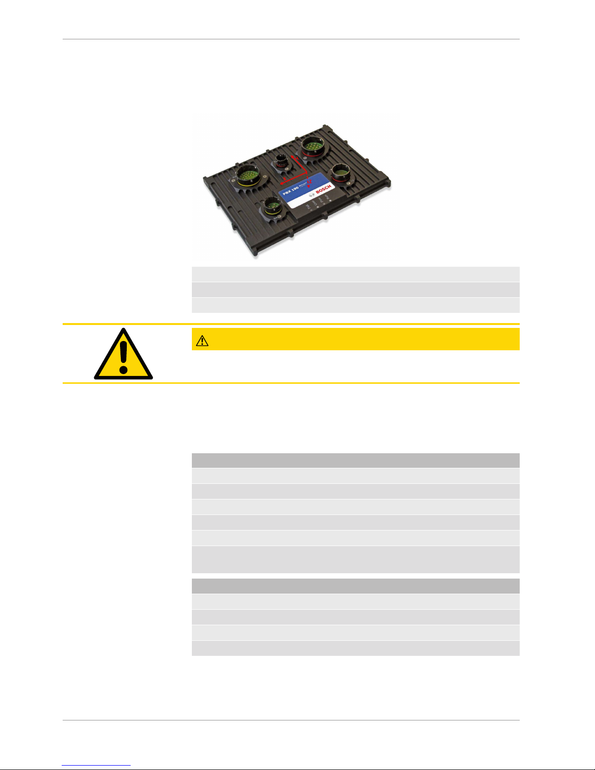
1 About PowerBox PBX 190
The Bosch PowerBox PBX 190 takes the whole Power Control Module concept much further than existing modules. It provides an effective and inspired alternative to conventional relays, circuit breakers, fuses and wires that can so often be a tangle of complexity
and untidiness around a typical racing car’s power junction box.
Bosch PowerBox PBX 190 is a compact and light weight module, measuring 245 x 183 x 37
mm (including connectors).
Bosch PowerBox PBX 190 has 52 outputs. All outputs are protected against reversed battery polarity. Current draw can be measured on all outputs from 0 mA.
Any of these channels can be controlled by various types and combinations of inputs.
You’ll find more information at Technical Specifications [}36].
Instead of using a conventional control program, Bosch PowerBox PBX 190 benefits from
a 667 MHz dual Core Processor and a multitasking operating system, allowing simultaneous executions of operations.
Please note that the maximum recommended current draw per channel is limited by the
connector contacts (wiring loom side) - not by Bosch PowerBox PBX 190s driver stages.
We have rated the individual channel’s current draw in relation to the connector manufacturer’s specifications.
Bosch PowerBox PBX 190 is programmed to shut overloaded channels down if the current
draw or internal junction temperatures exceed pre-set levels.
A smart algorithm allows automatically turning-on of loads with a high inrush current.
The current draws and channel status can be logged internally and exported via one of
the three available CAN bus.
WARNING
Please note that the PowerBox PBX 190 is not intended to be used to
control safety-critical systems on a vehicle, such as ABS braking,
power steering, etc..
Bosch Motorsport shall not be responsible for any incidental or consequential damages or
injuries that may occur if the unit is used to control these, or similar, safety-critical systems.
2 | Hardware
4/40 PowerBox_PBX_190_Manual Bosch Motorsport
2 Hardware
The Bosch PowerBox PBX 190 enclosure is CNC machined to the highest standards. The
two parts of the casing are sealed by an O-ring, located in a recess in the main half. A lip
in the lid presses on the O-ring and assures a water tight sealing (IP67). The connectors
are individually sealed.
2.1 Ventilation
To reach specified current values an airflow of 2 m/s over the PBX 190 housing is recommended.
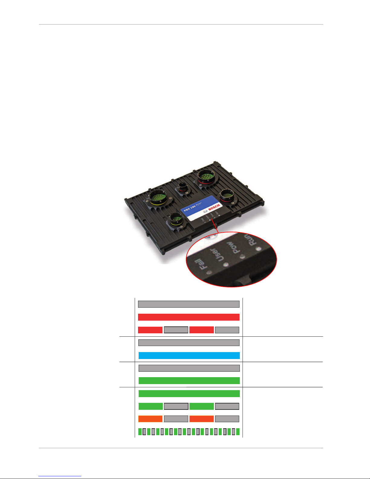
2.2 Status LEDs
Each LED on the PBX 190 has its own color code with different meanings.
The following table explains the different meanings:
Fail
Off
No error
Red solid
At least one entry in the error log
Red blinking (2 Hz)
At least one active error present
User
Off/Blue
Controlled by functionblock „User_LED“
Pow
Off
Power supply missing
Green solid
Power supply valid
Run
Green solid
No configuration active
Green blinking (2 Hz)
Configuration active
Orange blinking (2 Hz)
Configuration error
Green flickering (10 Hz)
Emergency state

Hardware | 2
Bosch Motorsport PowerBox_PBX_190_Manual 5/40
2.3 Pin Configuration
Connector X1: 37 Pins / 8STA6-24-37SA
Pin Signal Cont. [A] Peak [A]
A HS_15A X1_A 15 100
B HS_15A X1_B 15 100
C HS_15A X1_C 15 100
D HS_15A X1_D 15 100
E HS_15A X1_E 15 100
F HS_15A X1_F 15 100
G HS_15A X1_G 15 100
H HS_15A X1_H 15 100
J HS_15A X1_J 15 100
K HS_15A X1_K 15 100
L HS_15A X1_L 15 100
M HS_15A X1_M 15 100
N HS_15A X1_N 15 100
P PWM_15A X1_P 15 60
R PWM_15A X1_R 15 60
S PWM_15A X1_S 15 60
T PWM_15A X1_T 15 60
U HS_15A X1_U 15 100
V HS_15A X1_V 15 100
W HS_15A X1_W 15 100
X HS_15A X1_X 15 100
Y HS_15A X1_Y 15 100
Z HS_15A X1_Z 15 100
a HS_15A X1_a 1 15 100
b HS_15A X1_b 1 15 100
c PWM_15A X1_c 1 15 60
d PWM_15A X1_d 1 15 60
e PWM_15A X1_e 1 15 60
f PWM_15A X1_f 1 15 60
g HS_15A X1_g 1 15 100
h HS_15A X1_h 1 15 100
k HS_15A X1_k 1 15 100
m HS_15A X1_m 1 15 100
n HS_15A X1_n 1 15 100
p Power KL31 15 -
q Power KL31 15 -
r Power KL31 15 -

2 | Hardware
6/40 PowerBox_PBX_190_Manual Bosch Motorsport
Connector X2: 1 Pin / 8STA6-12-01BN261
Pin Signal Cont. [A] Peak [A]
1 Power Supply 12 V 200 240
Connector X3: 19 Pins / 8STA6-24-19SN
Pin Signal Cont. [A] Peak [A]
A HS_25A X3_A 25 150
B HS_25A X3_B 25 150
C HS_25A X3_C 25 150
D HS_25A X3_D 25 150
E HS_25A X3_E 25 150
F HS_25A X3_F 25 150
G + H HS_40A X3_G_H 40 150
J + T HS_40A X3_J_T 40 150
K + U HS_40A X3_K_U 40 150
L + N HS_40A X3_L_N 40 150
M HS_25A X3_M 25 150
P HS_25A X3_P 25 150
R HS_25A X3_R 25 150
S HS_25A X3_S 25 150
V Power KL31 25 -
Connector X4: 6 Pins / 8STA6-16-06SA
Pin Signal Cont. [A] Peak [A]
A HS48V_25A X4_A 25 100
B HS48V_25A X4_B 25 100
C HS48V_25A X4_C 25 100
D HS48V_25A X4_D 25 100
E Supply up to 48 V for X4 25 35
F Supply up to 48 V for X4 25 35
Connector X5: 66 Pins / 8STA6-18-35SN
Pin Signal
1 Analog Input X5_01 0 to 5 V, Pull-up
2 Analog Input X5_02 0 to 5 V, Pull-up
3 Analog Input X5_03 0 to 5 V, Pull-up
4 Analog Input X5_04 0 to 5 V, Pull-up
5 Analog Input X5_05 0 to 5 V, Pull-up
6 Analog Input X5_06 0 to 5 V, Pull-up
7 Analog Input X5_07 0 to 5 V, Pull-up
8 Analog Input X5_08 0 to 5 V, Pull-up
9 CAN 3 Interface Low-Level Max. 1 Mbaud
10 Analog Input X5_10 0 to 5 V, Pull-up
11 Analog Input X5_11 0 to 5 V, Pull-up
12 Analog Input X5_12 0 to 5 V, Pull-up

Hardware | 2
Bosch Motorsport PowerBox_PBX_190_Manual 7/40
Connector X5: 66 Pins / 8STA6-18-35SN
13 Digital Input X5_13 0 to 12 V, Pull-up, Pull-down
14 Digital Input X5_14 0 to 12 V, Pull-up, Pull-down
15 CAN 3 Interface High-Level Max. 1 Mbaud
16 LIN Control of Bosch Motorsport LIN
devices included. Support of
other devices on request.
17 Analog Input X5_17 0 to 5 V, Pull-up
18 Analog Input X5_18 0 to 5 V, Pull-up
19 DGND-fused 5 A
20 DGND-fused 5 A
21 Digital Input X5_21 0 to 12 V, Pull-up, Pull-down
22 Digital Input X5_22 0 to 12 V, Pull-up, Pull-down
23 SERCOS1 TXP
24 SERCOS1 TXN
25 do not connect (use for internal debugging)
26 do not connect (use for internal debugging)
27 Analog Input X5_27 0 to 5 V, Pull-up
28 Digital Input X5_28 0 to 12 V, Pull-up, Pull-down
29 Digital Input X5_29 0 to 12 V, Pull-up, Pull-down
30 Analog Input X5_30 0 to 5 V, Pull-up
31 KL31-fused
32 SERCOS1 RXP
33 SERCOS1 RXN
34 do not connect (use for internal debugging)
35 do not connect (use for internal debugging)
36 Digital Input X5_36 0 to 12 V, Pull-up, Pull-down
37 Digital Input X5_37 0 to 12 V, Pull-up, Pull-down
38 Analog_Screen
39 Analog Input X5_39 0 to 5 V, Pull-up
40 KL31-fused
41 SERCOS2 RXP
42 SERCOS2 RXN
43 Digital Input X5_43 0 to 12 V, Pull-up, Pull-down
44 Digital Input X5_44 0 to 12 V, Pull-up, Pull-down
45 Sensor GND for X5_51 5 A
46 Timesync
47 COM_Screen
48 CAN 1 Interface High-Level Max. 1 Mbaud
49 SERCOS2 TXP
50 SERCOS2_TXN
51 Powersupply_5V X5_51 400 mA
52 Sensor GND for X5_58 5 A

2 | Hardware
8/40 PowerBox_PBX_190_Manual Bosch Motorsport
Connector X5: 66 Pins / 8STA6-18-35SN
53 ETHERNET1 RXN 10/100 Mbps
54 ETHERNET0 RXN 10/100 Mbps
55 CAN 2 Interface Low-Level Max. 1 Mbaud
56 CAN 1 Interface Low-Level Max. 1 Mbaud
57 Analog Input X5_57 0 to 5 V, Pull-up
58 Powersupply_5V X5_58 400 mA
59 ETHERNET1 RXP 10/100 Mbps
60 ETHERNET1 TXN 10/100 Mbps
61 ETHERNET0 TXN 10/100 Mbps
62 CAN 2 Interface High-Level Max. 1 Mbaud
63 Analog Input X5_63 0 to 5 V, Pull-up
64 ETHERNET1 TXP 10/100 Mbps
65 ETHERNET0 RXP 10/100 Mbps
66 ETHERNET0 TXP 10/100 Mbps
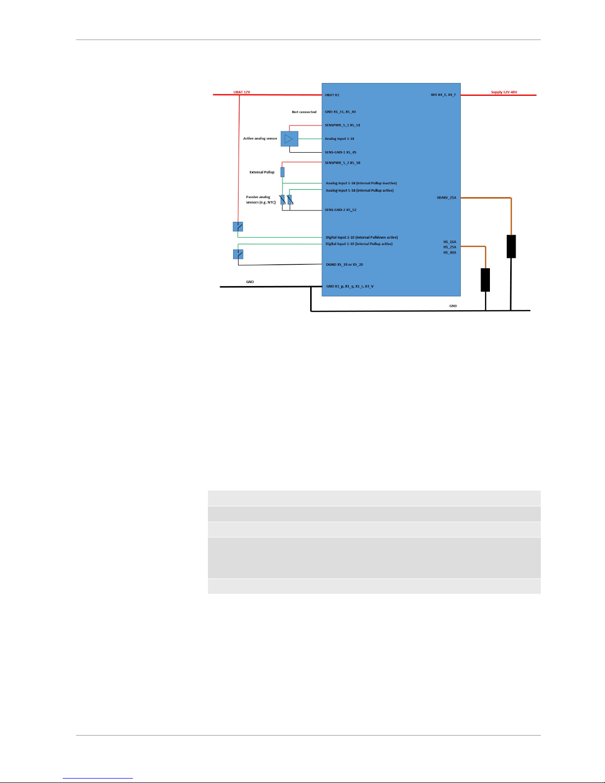
2.4 Supply Concept
The battery supply of the device and the supply of all switches is done via X2. The best
way to connect the PowerBox to GND is only using X1_p, X1_q, X1_r and X3_V. GND current is limited to 75 A.
KL31-fused pins (X5_31 and X5_40) can also be used to connect the supply to the PowerBox with GND. This is only recommended when only highside switches and no internal
freewheeling diodes are used.
To supply active sensors with 5 V use SENSPWR_5_1 (X5_51) and SENSPWR_5_2 (X5_58).
SENS-GND-1 (X5_45) and SENS-GND-2 (X5_52) are the reference ground of these sensor
supply voltages. Use these two ground pins preferred for analog sensor reference.
For digital inputs ground reference pins X5_19 and X5_20 can be used.
Hardware | 2
Bosch Motorsport PowerBox_PBX_190_Manual 9/40
Recommended wiring
2.5 48 V Stages
GND of 48 V and GND of 12 V battery must be shorted. A galvanic isolation of supplies is
not supported. An external capacitor is recommended to limit voltages spikes on the supply line at load drop.
It is recommended to use an external fuse when using 48 V to be safe in case of a shortcut
to GND. For details using 48 V in PBX 190 please contact Bosch Motorsport.
2.6 Current measurement
Each Output stage has its own shunt resistor to measure the output current. Here you can
find an overview of the current measurement accuracy.
Measurement range Accuracy
HS_15A 0 to 95 A 1 % ±50 mA
HS_25A, HS_40A 0 to 190 A 1 % ±100 mA
PWM_15A -40 to 40 A 1 % ±50 mA (depends on
PWM frequency and duty
cycle)
HS48V_25A 0 to 80 A 1 % ±50 mA
2 | Hardware
10/40 PowerBox_PBX_190_Manual Bosch Motorsport
2.7 G-Sensors
PBX 190 has implemented a low and a high G-Sensor. Below you can see the orientation
of the measurement axis and the accuracy of the sensors.
Measurement range Accuracy
Low G-Sensor ±20 g in each direction 1 % ±0.2 g
High-G-Sensor ±200 g in each direction 1 % ±3 g
CAUTION
The sensors functionality is only guaranteed when device temperature is max. 85°C.
2.8 Warnings and shutdown Thresholds
Due to thermal or pin current overload there are several warnings and shutdown
thresholds. You can see an overview of these below.
Overcurrent
Warning overcurrent X2 210 A for 0.2 s
Shutdown overcurrent X2 240 A for 2 s
Warning overcurrent X4_E and X4_F 55 A for 0.2 s
Shutdown overcurrent X4_E and X4_F 70 A for 2 s
Warning overcurrent over GND Pins on X1 and X3 75 A for 0.2 s
Shutdown overcurrent over GND Pins on X1 andX380 A for 2 s
Overtemperatur
Warning overtemperature CPU 95°C for 2 s
Shutdown overtemperature CPU 100°C for 2 s
Warning overtemperature Device 95°C for 2 s
Shutdown overtemperature Device 115°C for 2 s

PBX Suite Installation | 3
Bosch Motorsport PowerBox_PBX_190_Manual 11/40
3 PBX Suite Installation
The setup file for the PBX Suite is provided at the Bosch Motorsport internet homepage at
the product page of the PowerBox PBX 190.
For the PBX Suite a personal license key is required. This can be requested at order time of
a PowerBox PBX 190 device or later by mail to LicenseMotorsport.BEG@de.bosch.com
(For evaluation purpose a 30 days limited setup is also available without needing a license).
The installation requires administrator rights.
Start the installation by running setup.exe and follow the wizard steps.
4 | The Structure Editor: Create a new configuration
12/40 PowerBox_PBX_190_Manual Bosch Motorsport
4 The Structure Editor: Create a new
configuration
A configuration is the unit you exchange between the programming tool PBX Suite and
your PowerBox PBX 190 after all changes and modifications.
For creating a configuration we developed the PBX Suite. This software tool enables visual
programming of the configuration of your PowerBox.
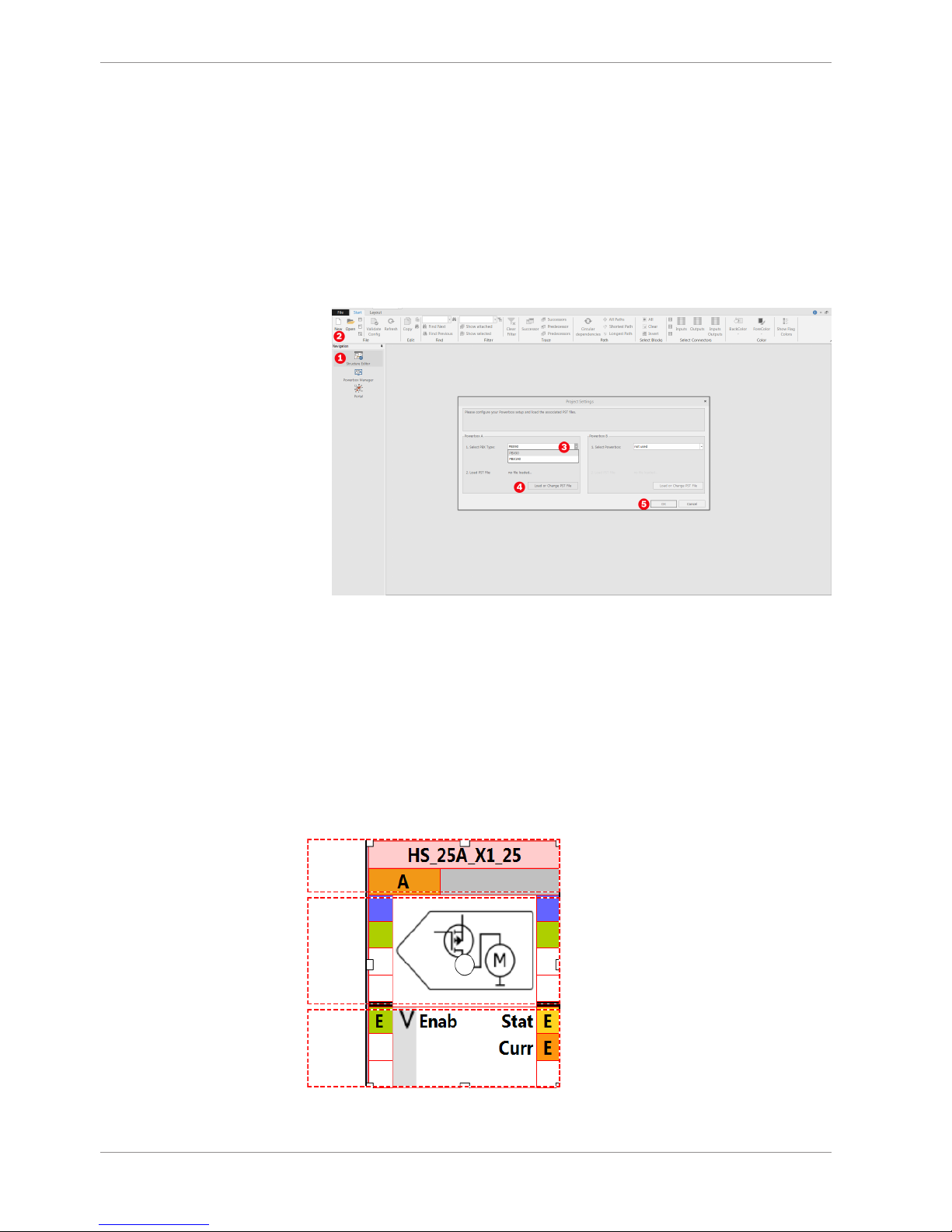
– Start the program PBX Suite.
– Click Structure Editor in the menu box on the left side (1).
– Click New (2).
– Select your PBX type (3).
– Load the corresponding PST file (4).
– Confirm by clicking OK (5).
4.1 Function Blocks
The key technology of the PBX Suite is the function block. All functions of the PowerBox
can be programmed and modified by using a string of function blocks.
Every function block is divided into three parts:
C
B
A
– A is the top part that includes the unique name of the function block. It is user
changeable.
 Loading...