

Page 1
Ú Installation instructions
Gas hob
02
210599
Page 2

Page 3

Ú Installation instructions
Safety precautions .....................................................................4
Before installing .........................................................................4
Preparing the units..................................................................... 4
Installation of appliance ............................................................5
Setting up the appliance ...................................................................5
Removal of hob ..........................................................................6
Set-up, gas and electricity connection..................................... 6
Gas connection ...................................................................................6
Faults in the gas installation/smell of gas .....................................6
Electrical connection ..........................................................................6
Types of connection ..................................................................7
Liquid gas connection (LPG) ............................................................7
Gas connector ............................................................................8
Leak test and function test........................................................8
Check the gas connection ................................................................8
Checking the burner nozzles............................................................8
Checking the bypass valves.............................................................8
Correct flame formation............................................................. 8
Burner ...................................................................................................8
Technical data – Gas.................................................................. 9
3
Page 4
Safety precautions
Read the appliance instructions before installing and using.
The graphics in these Assembly instructions are given as a
guide only.
The manufacturer is exempt from all liability if this manual's
requirements are not complied with.
All operations relating to installation, regulation and
conversion to other gas types must be carried out by an
authorised installation engineer, respecting all applicable
regulations, standards and the specifications of the local gas
and electricity providers.
You are recommended to contact the Technical Assistance
Service to convert to another gas type.
Before you begin, turn off the appliance's electricity and gas
supply.
This appliance has been designed for home use only, not for
commercial or professional use. This appliance cannot be
installed on yachts or in caravans. The warranty will only be
valid if the appliance is used for the purpose for which it was
designed.
Before installing
This appliance is class 3 type, according to the EN 30-1-1
regulation for gas appliances: built-in appliance.
This appliance is classified in accordance with SASO-168 in
class 4.1.
The units next to the appliance must be made of non-flammable
materials. The laminated covering and glue for adhering it must
be heat resistant.
After connecting the appliance, check that the local conditions
(type of gas and pressure) are compatible with the appliance
settings. The permissible appliance settings can be found on
the label or rating plate.
These instructions are only valid if the appropriate country
symbol appears on the appliance. If the symbol does not
appear on the appliance, it is necessary to refer to the
technical instructions which will provide the necessary
instructions concerning modification of the appliance to the
conditions of use of the country.
This appliance can only be installed in a well-ventilated place in
accordance with existing regulations and ventilation
specifications. The appliance must not be connected to a
combustion product removal device.
The supply cable must be attached to the unit to prevent it from
touching hot parts of the oven or hob.
Appliances with electrical supply must be earthed.
Do not tamper with the appliance's interior. If necessary, call
our Technical Assistance Service.
This appliance cannot be installed above fridges, washing
machines, dishwashers or similar.
If the hob is installed above an oven, it must have forced
ventilation. Check the dimensions of the oven in your
installation instructions.
If an extractor hood is fitted, this must be done according to the
installation instructions and always allowing for a vertical
minimum clearance of 650 mm to the hob.
Preparing the units
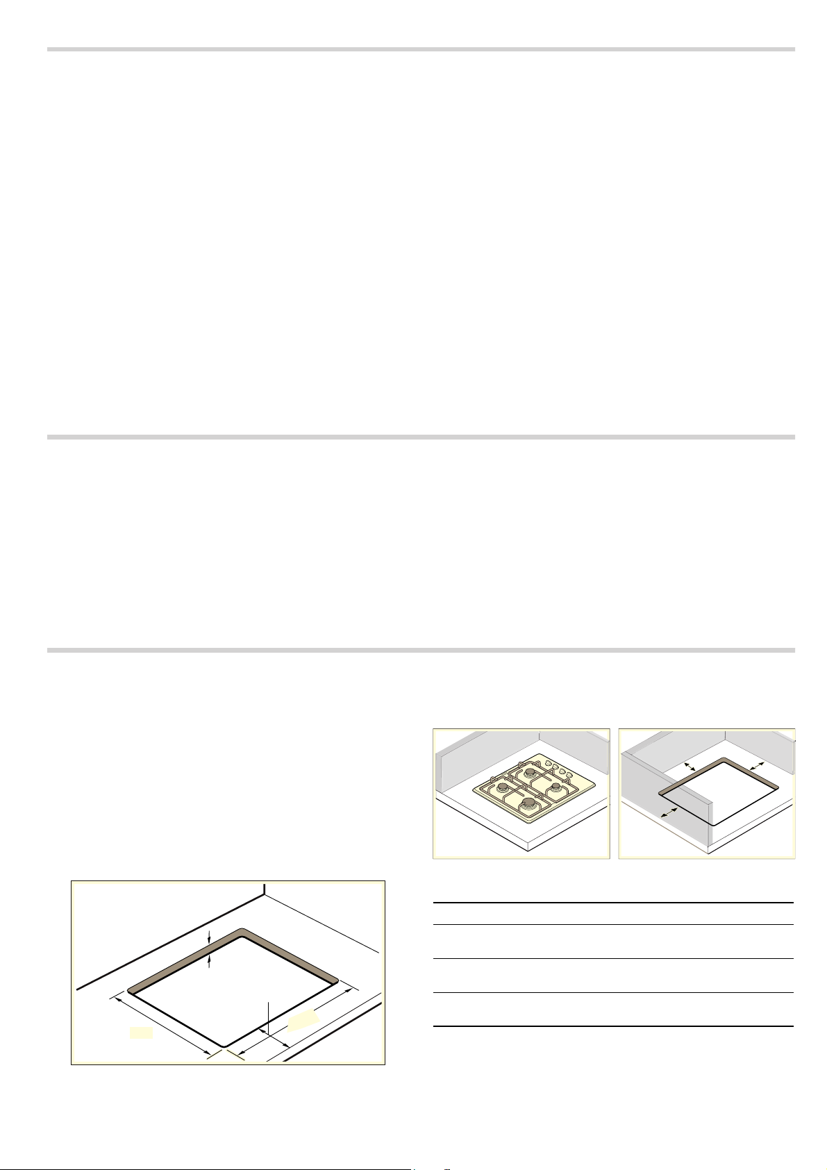
Make an appropriate size cut in the work surface.
The appliance must be set up and inserted in accordance with
the specified dimensions. The appliance must not be set up on
any other object.
If the hob is electric or mixed (gas and electricity) and there is
no oven below, place a non-flammable separator (e.g. metal or
plywood) 10 mm from the bottom of the hob. This will prevent
access to the base of the hob.If the hob is gas, it is
recommendable to place the separator at the same distance.
Seal all work surfaces made of wood with special sealer/glue
to protect it against moisture damage.
¸
PLQ
PD[
PLQ
)
&
(
%
$
Distance Designation
A Distance between the appliance and the right
vertical surface
B Distance between the appliance and the left ver-
tical surface
C Distance between the appliance and the rear
vertical surface
Caution!
■ You can install the appliance between two vertical surfaces
that are next to each other, e.g. D and F or E and F.
■ You cannot install the appliance between two vertical
surfaces that are opposite each other, e.g. D and E.
'
4
Page 5

When you install the built-in cooker, comply with the dimensions
given in the table below.
Note: Use the data in the table below that corresponds to your
appliance.
Caution!
If surfaces A and B are available, do not place the appliance on
a surface.
Installation of appliance
Note: Wear protective gloves to fit the hob.
Remove the pan support, handles, burner cap and burner
heads.
Appliance type Minimum
Products with hob
plate made of
glass
Products with hob
plate made from
steel/enamel
Note: Determine the distances that are listed in the table from
the surface that is closest to the appliance.
distance A
(mm)
100 60 50
100 80 50
Minimum
distance B
(mm)
Minimum distance C (mm)
Turn the appliance over carefully and place it on a soft cloth.
Make sure that the ignition parts are not damaged.
The adhesive seal provided prevents leaks. Adhere it to the
work surface around the cut-out. It must be adhered around the
edge of the area cut out.
Fitting the appliance onto the kitchen unit:
1. Remove the clips from the accessory bag and screw them
into the position indicated so that they can turn freely.
2. Insert and centre the hob.
Press the sides of the hob until it is supported around its
entire perimeter.
3. Turn the clips and tighten them fully.
The position of the clips depends on how thick the work
surface is.
Do not stick the hob onto the worktop with silicone.
Setting up the appliance
■ The distance between the top edge of the cooker and the
bottom edge of the extractor hood must meet the
requirements of the extractor hood manufacturer.
■ Ensure that the appliance is not moved again after set up.
■ The underside of the appliance heats up during operation.
We therefore recommend that you install a guard plate on the
underside of the appliance.
PD[
PLQ
5
Page 6

Removal of hob
Turn off the appliance's electricity and gas supply. Unscrew the clips and proceed in the reverse order to
installation.
Set-up, gas and electricity connection
Gas connection
Installation must only be performed by an approved expert or a
licensed after-sales service engineer in accordance with the
instructions specified in the "Installation instructions".
For the licensed expert or after-sales service
Caution!
The setting values for this appliance are specified on the rating
plate on the back of the appliance. The gas type set in the
factory is marked with an asterisk (*).
If the star symbol appears next to the label "NG", the appliance
is set up for natural gas, and if it appears next to "LPG", the
appliance is set up for liquefied gas.
Caution!
Before connecting the appliance, check whether the local
connection conditions (gas type and pressure) correspond to
the appliance settings. If a change to the appliance settings is
necessary, make the change with the aid of the instructions in
the "Installation instructions".
Caution!
Connect the LPG nipple that is included in the scope of delivery
for the appliance to the collector connecting piece upstream of
the gas connection.
Caution!
This appliance is not connected to a waste gas main. It must be
connected and commissioned in accordance with the
installation conditions. Do not connect the appliance to a waste
gas main. All ventilation regulations must be observed.
Caution!
The gas connection must be made via a fixed, i.e. not mobile
connection (gas line) or via a safety hose.
Caution!
If using the safety hose, ensure that the hose is not trapped or
crushed. The hose must not come into contact with hot
surfaces.
Caution!
The gas connection must have an easily accessible locking
device.
Safety information
The nominal operating pressure of the appliance is:
for natural gas (G20) 20 mBar, for natural gas (G25) 25 mBar,
for LPG (G30) 30 mBar, for LPG (G31) 37 mBar. The appliance
must be operated at these pressure values. All data on the
rating plate of your appliance relates to these pressure values.
The manufacturer is not responsible for results, performance or
any risk caused by operating the appliance at different values.
: If the gas pressure in your gas supply grid!
for natural gas (G20) is higher than 25 mBar, for natural gas
(G25) is higher than 30 mBar, for LPG (G30) is higher than 36
mBar, for LPG (G31) is higher than 45 mBar, you must use
your appliance in conjunction with a suitable gas regulator, for
safety reasons. Connection, maintenance and configuration of
the gas regulator must be performed by an authorised
installation expert. If you do not know the gas pressure in your
gas supply grid, please ask your local supply grid operator.
Faults in the gas installation/smell of gas
If you notice a smell of gas or faults in the gas installation, you
must:
: WHAT TO DO IF YOU SMELL GAS!
Escaping gas may cause an explosion.
If you smell gas or notice any faults in the gas installation:
■ Immediately shut off the gas supply or close the gas cylinder
valve.
■ Immediately extinguish all naked flames and cigarettes.
■ Do not use any light or appliance switches and do not pull
any plugs out of sockets. Do not use any telephones or
mobile phones within the building.
■ Open windows and ventilate the room.
■ Call the aftersales service or the gas supplier.
Electrical connection
Caution!
■ Have the appliance set up by your after-sales service. A 16 A
fuse is required for connection. The appliance is designed for
operation at 220-240 V.
■ If the electricity supply drops below 180 V, the electrical
ignition system does not work.
■ Any damage arising from the appliance being connected
incorrectly will invalidate the guarantee.
■ If the supply cord is damaged, it must be replaced by the
manufacturer, its service agent or similarly qualified persons
in order to avoid a hazard.
For the after-sales service
Caution!
The electrical connection must only be carried out by a
licensed service technician. Observe the instructions of the
relevant electricity provider.
Caution!
The appliance must be connected in accordance with the data
on the rating plate.
Caution!
The mains voltage must correspond to the voltage specified on
the label or rating plate.
Caution!
Only connect the appliance to an electrical connection that
meets the applicable provisions. The socket must be easily
accessible so that you can disconnect the appliance from the
electricity supply if necessary.
Caution!
Please ensure the availability of a multi-pin disconnecting
system.
Caution!
Never use extension cables or multiple plugs.
6
Page 7

Caution!
For safety reasons, this appliance must only be connected to
an earthed connection. If the safety earth terminal does not
comply with regulations, safety against electrical hazards is not
guaranteed.
Caution!
You must use a H 05 W-F type cable or equivalent for the
appliance connection.
Connection for models with mains cable without plug (optional):
Caution!
Appliances fitted with three-core cables must be earthed.
Types of connection
These instructions apply only when the appliance is set up in
countries that are indicated on the rating plate.
Note: If the appliance is set up, connected and used in a
country that is not indicated on the rating plate, installation and
assembly instructions must be used that contain data and
information on the valid connection conditions in the relevant
country.
The gas connection must be located in a position where the
stop tap is accessible.
Liquid gas connection (LPG)
Caution!
Observe the country-specific guidelines.
If liquid gas (LPG) is used, the gas connection should be
established via a gas hose or a fixed connection.
Important information when using a gas hose:
■ A safety gas hose or a plastic hose (8 mm diameter) must be
used.
■ It must be secured to the gas connection using an approved
connecting device (for example, a hose clamp).
■ The hose must be short and completely leak-tight. The hose
can have a maximum length of 1.5 m. Observe the current
guidelines.
■ The gas hose must be replaced at least once a year.
Fit the flexible safety gas hose and use a screw connection or a
cable clamp to tighten it securely.
After establishing the connection, carry out a leak test. See the
section "Leak test".
Caution!
Connect the LPG nipple that is included in the scope of delivery
for the appliance to the collector connecting piece upstream of
the gas connection.
Connect the wires with the mains cable according to the
following colour coding:
Green/yellow
Blue Neutral
Brown Phase
If the mains cable has to be replaced: Connect the cable to the
appliance according to the wiring diagram.
1P
6:
Earth
<
6:
/3***
/3***
7
Page 8

Gas connector
(*) Seal
(*) Connecting piece for liquid gas
(LPG: G30, G31)
Leak test and function test
Connecting piece
: Risk of explosion!
Avoid sparking. Do not use an open flame.
Perform the leak test only with a suitable leakage spray.
In the event of a gas leak
Shut off the gas supply.
Ensure that the room affected is well ventilated.
Check the gas and valve connections again. Repeat the leak
test.
The leak test must be performed by two people, in accordance
with the following instructions.
Check the gas connection
1. Open the gas supply.
2. Spray the gas connection with a leakage spray.
If small bubbles or foam form, indicating a gas leak, follow the
instructions in the section entitled "In the event of a gas leak".
Checking the burner nozzles
1. Open the gas supply.
Carry out the leak test separately for each nozzle.
Correct flame formation
2. Carefully close the hole in the burner nozzle to be checked
using your finger or a suitable device.
3. Spray the nozzle with a leakage spray.
4. Press the function selector and turn it anti-clockwise. This
supplies the nozzle with gas.
If small bubbles or foam form, indicating a gas leak, follow the
instructions in the section entitled "In the event of a gas leak".
Checking the bypass valves
1. Open the gas supply.
Carry out the leak test separately for each bypass screw.
2. Carefully close the hole in the burner nozzle to be checked
using your finger or a suitable device.
3. Spray the nozzle in the burner to be checked with a leakage
spray.
4. Push the control knob and turn it anti-clockwise. This supplies
the nozzle with gas.
If small bubbles or foam form, indicating a gas leak, follow the
instructions in the section entitled "In the event of a gas leak".
Burner
The burning behaviour and soot formation must be checked for
each burner after the gas type has been changed.
If there is a problem, the nozzle values must be compared with
the values in the table.
1. Ignite the gas burner in accordance with the instructions in
the operating instructions.
2. Turn the control knob to the small flame setting.
Check whether the flame safety system is operating by
holding the flame at the "Small flame" setting for one minute.
8
3. Check the correct burner behaviour for large and small
flames. The flame should burn evenly and constantly.
4. Turn the control knob quickly from the large flame to the
small flame and back again. Repeat this process several
times. The gas flame must not flicker or go out.
Page 9

Technical data – Gas
The different types of gas and the corresponding values are
listed here.
Nozzle values for economy burners
G20 G25 G30 G 30
Gas pressure (mbar) 20 25 29 50
Nozzle (mm) 0.72 0.72 0.50 0,46
Bypass nozzle (mm) 0.3 0.3 0.3 0,3
Input power, max. (kW) 1 1 1 1
Input power, min (kW) ≤0.33 ≤0.33 ≤0.33 ≤0,33
Gas flow at 15 °C and 1013 mbar m³/h 0.095 0.111 - -
Gas flow at 15 °C and 1013 mbar g/h - - 73 73
Nozzle values for normal burners
G20 G25 G30 G 30
Gas pressure (mbar) 20 25 29 50
Nozzle (mm) 1.00 0.98 0.67 0,60
Bypass nozzle (mm) 0.32 0.32 0.32 0,32
Input power, max. (kW) 1.75 1.75 1.75 1,75
Input power, min (kW) ≤0.35 ≤0.35 ≤0.9 ≤0,9
Gas flow at 15 °C and 1013 mbar m³/h 0.167 0.194 - -
Gas flow at 15 °C and 1013 mbar g/h - - 127 127
Nozzle values for larger burners (optional)
G20 G25 G30 G 30
Gas pressure (mbar) 20 25 29 50
Nozzle (mm) 1.15 1.28 0.85 0,78
Bypass nozzle (mm) 0.39 0.39 0.39 0,39
Input power, max. (kW) 3 3 3 3
Input power, min (kW) ≤0.50 ≤0.50 ≤1.3 ≤1,3
Gas flow at 15 °C and 1013 mbar m³/h 0.286 0.333 - -
Gas flow at 15 °C and 1013 mbar g/h - - 218 218
Nozzle values for mini woks (optional)
G20 G25 G30 G 30
Gas pressure (mbar) 20 25 29 50
Nozzle (mm) 1.03 1.04 0.68 0,60
Bypass nozzle (mm) 0.61 0.61 0.61 0,61
Input power, max. (kW) 3.3 3.3 3.3 3,3
Input power, min (kW) ≤1.55 ≤1.55 ≤1.55 ≤1,55
Gas flow at 15 °C and 1013 mbar m³/h 0.314 0.366 - -
Gas flow at 15 °C and 1013 mbar g/h - - 240 240
9
Page 10

Page 11

Page 12

*9001448611*
9001448611
 Loading...