

Bosch NUC-50051-F2M, NUC-51022-F2, NUC-51022-F2M, NUC-51022-F4, NUC-51051-F2 User Manual
...
Camera Browser Interface
FLEXIDOME IP micro 5000
en Software manual


Camera Browser
Interface
Table of contents
Table of Contents | en 3
1
1.1 System requirements 10
1.2 Establishing the connection 10
1.2.1 Password protection in camera 11
1.3 Protected network 11
2
2.1 Live page 12
2.2 Playback 12
2.3 Settings 12
3
3.1 Live page 13
3.1.1 Image selection 13
3.1.2 View Control ROI 14
3.1.3 System Log / Event Log 15
3.1.4 Saving snapshots 15
3.1.5 Recording video sequences 15
3.1.6 Running recording program 16
3.1.7 Processor load 16
3.1.8 Status icons 16
3.2 Playback 18
3.2.1 Selecting recordings for playback 18
3.2.2 Exporting tracks 18
3.2.3 Searching for tracks 19
3.2.4 Controlling playback 19
4
4.1 Device Access 21
4.2 Date/Time 22
4.3 Network 22
4.4 Encoder 23
4.5 Recording 23
4.6 System Overview 24
5
5.1 Identification 25
Bosch Security Systems 2014.03 | v1.59 | AM18-Q0671
Browser connection 10
System overview 12
Operation via the browser 13
Basic Mode 21
General settings 25

4 en | Table of Contents
Camera Browser
Interface
5.1.1 Naming 25
5.1.2 ID 25
5.1.3 iSCSI Initiator extension 25
5.2 Password 26
5.2.1 Enter Password 26
5.2.2 Confirm password 26
5.3 Date/Time 27
5.3.1 Date format 27
5.3.2 Device date / Device time 27
5.3.3 Device time zone 27
5.3.4 Daylight saving time 27
5.3.5 Time server IP address 28
5.3.6 Time server type 28
5.4 Display Stamping 29
5.4.1 Camera name stamping 29
5.4.2 Time stamping 29
5.4.3 Display milliseconds 29
5.4.4 Alarm mode stamping 29
5.4.5 Alarm message 30
5.4.6 Transparent stamping 30
5.4.7 Video authentication 30
5.5 GB/T 28181 30
6
Web Interface 31
6.1 Appearance 31
6.1.1 Website language 31
6.1.2 Company logo 31
6.1.3 Device logo 31
6.1.4 Show VCA metadata 31
6.1.5 Show overlay icons 31
6.1.6 Select video player 32
6.1.7 JPEG size, interval and quality 32
6.2 LIVE Functions 33
6.2.1 Lease time [s] 33
6.2.2 Show event log 33
6.2.3 Show system log 33
2014.03 | v1.59 | AM18-Q0671 Bosch Security Systems

Camera Browser
Interface
Table of Contents | en 5
6.2.4 Allow snapshots 33
6.2.5 Allow local recording 33
6.2.6 I-frames-only stream 34
6.2.7 Path for JPEG and video files 34
6.3 Logging 35
6.3.1 Save event log 35
6.3.2 Save system log 35
7
Camera 36
7.1 Installer Menu 36
7.1.1 Base frame rate 36
7.1.2 Mirror image 36
7.1.3 Flip image 36
7.1.4 Reboot device 36
7.1.5 Factory defaults 36
7.2 Picture settings – User mode 37
7.2.1 Current mode 37
7.2.2 Mode ID 37
7.2.3 Copy mode to 37
7.2.4 Restore Mode Defaults 37
7.2.5 User mode factory defaults 37
7.3 Picture settings – Color 39
7.3.1 White balance 39
7.4 Picture settings – ALC 41
7.4.1 ALC mode 41
7.4.2 ALC level 41
7.4.3 Exposure/frame rate 41
7.5 Picture settings – Enhance 42
7.5.1 Sharpness level 42
7.5.2 Backlight Compensation 42
7.5.3 Contrast enhancement 42
7.5.4 Intelligent DNR 42
7.6 Picture settings – User mode scheduler 43
7.7 Encoder Settings 44
7.8 Privacy Masks 45
7.9 Pixel Counter 46
Bosch Security Systems 2014.03 | v1.59 | AM18-Q0671

6 en | Table of Contents
Camera Browser
Interface
8
Encoder Settings 47
8.1 Encoder Profile 48
8.1.1 Pre-defined profiles 48
8.1.2 Changing a profile 48
8.1.3 Profile name 49
8.1.4 Target bit rate 49
8.1.5 Maximum bit rate 49
8.1.6 Encoding interval 49
8.1.7 Standard definition video resolution 49
8.1.8 Expert Settings 50
8.1.9 Default 51
8.2 Encoder Streams 52
8.2.1 H.264 settings 52
8.2.2 JPEG stream 53
8.3 Encoder Regions 54
8.3.1 Regions 54
9
Recording 55
9.1 Storage Management 55
9.1.1 Device manager 55
9.1.2 Recording media 56
9.1.3 Activating and configuring storage media 56
9.1.4 Formatting storage media 57
9.1.5 Deactivating storage media 57
9.2 Recording Profiles 58
9.2.1 Recording track selection 58
9.2.2 Standard recording 59
9.2.3 Alarm recording 59
9.3 Maximum Retention Time 61
9.4 Recording Scheduler 62
9.4.1 Weekdays 62
9.4.2 Holidays 62
9.4.3 Profile names 63
9.4.4 Activate recording 63
9.4.5 Recording status 63
9.5 Recording Status 64
2014.03 | v1.59 | AM18-Q0671 Bosch Security Systems

Camera Browser
Interface
Table of Contents | en 7
10
Alarm 65
10.1 Alarm Connections 65
10.1.1 Connect on alarm 65
10.1.2 Number of destination IP address 65
10.1.3 Destination IP address 65
10.1.4 Destination password 65
10.1.5 Video transmission 66
10.1.6 Stream 66
10.1.7 Remote port 66
10.1.8 Video output 66
10.1.9 Decoder 67
10.1.10 SSL encryption 67
10.1.11 Auto-connect 67
10.2 Video Content Analyses (VCA) 68
10.3 Alarm E-Mail 69
10.3.1 Send alarm e-mail 69
10.3.2 Mail server IP address 69
10.3.3 SMTP user name 69
10.3.4 SMTP password 69
10.3.5 Format 69
10.3.6 Image size 69
10.3.7 Attach JPEG from camera 70
10.3.8 Destination address 70
10.3.9 Sender name 70
10.3.10 Test e-mail 70
10.4 Alarm Task Editor 71
11
Setting up VCA 72
11.1 VCA - Silent VCA 72
11.2 VCA - Profiles 73
11.2.1 Aggregation time [s] 73
11.2.2 Analysis type 73
11.2.3 Motion detector 74
11.2.4 Tamper detection 75
11.3 VCA - Scheduled 79
11.3.1 Weekdays 79
Bosch Security Systems 2014.03 | v1.59 | AM18-Q0671

8 en | Table of Contents
Camera Browser
Interface
11.3.2 Holidays 79
11.4 VCA - Event triggered 81
11.4.1 Trigger 81
11.4.2 Trigger active 81
11.4.3 Trigger inactive 81
11.4.4 Delay [s] 81
12
Network 82
12.1 Network Access 82
12.1.1 Automatic IP assignment 82
12.1.2 IP V4 address 82
12.1.3 IP V6 address 83
12.1.4 DNS server address 83
12.1.5 Video transmission 83
12.1.6 HTTP browser port 83
12.1.7 HTTPS browser port 83
12.1.8 RCP+ port 1756 84
12.1.9 Telnet support 84
12.1.10 Interface mode ETH 84
12.1.11 Network MSS [Byte] 84
12.1.12 iSCSI MSS [Byte] 85
12.1.13 Network MTU [Byte] 85
12.2 DynDNS 86
12.2.1 Enable DynDNS 86
12.2.2 Provider 86
12.2.3 Host name 86
12.2.4 User name 86
12.2.5 Password 86
12.2.6 Force registration now 86
12.2.7 Status 87
12.3 Advanced 88
12.3.1 Cloud-based Services 88
12.3.2 RTSP port 88
12.3.3 Authentication (802.1x) 88
12.3.4 TCP metadata input 88
12.4 Network Management 89
2014.03 | v1.59 | AM18-Q0671 Bosch Security Systems

Camera Browser
Interface
Table of Contents | en 9
12.4.1 SNMP 89
12.4.2 UPnP 89
12.4.3 Quality of Service 90
12.5 Multicast 91
12.5.1 Enable 91
12.5.2 Multicast Address 91
12.5.3 Port 92
12.5.4 Streaming 92
12.5.5 Multicast packet TTL 92
12.6 Image Posting 93
12.6.1 JPEG posting 93
12.7 Accounts 94
12.8 IPv4 Filter 95
13
Service 96
13.1 Maintenance 96
13.1.1 Update server 96
13.1.2 Firmware 96
13.1.3 Upload History 97
13.1.4 Configuration 97
13.1.5 SSL certificate 97
13.1.6 Maintenance log 98
13.2 System Overview 99
Bosch Security Systems 2014.03 | v1.59 | AM18-Q0671

10 en | Browser connection
Camera Browser
Interface
1
1.1
1.2
Browser connection
A computer with Microsoft Internet Explorer is used to receive
live images, control the unit, and replay stored sequences. The
unit is configured over the network using the browser.
System requirements
– Network access (Intranet or Internet)
– Microsoft Internet Explorer version 9 (32-bit)
– Screen resolution at least 1024 × 768 pixels
– 16- or 32-bit color depth
– JVM installed
The Web browser must be configured to enable Cookies from
the IP address of the unit.
In Windows Vista, deactivate protected mode on the Security
tab under Internet Options.
To play back live video images, an appropriate ActiveX must be
installed on the computer. If necessary, install
Bosch Video Client.
Establishing the connection
The unit must have a valid IP address to operate on your
network and a compatible subnet mask. By default, DHCP is preset at the factory to On and so your DHCP server assigns an IP
address. With no DHCP server the default address is
192.168.0.1
1. Start the Web browser.
2. Enter the IP address of the unit as the URL.
3. During initial installation, confirm any security questions
that appear.
2014.03 | v1.59 | AM18-Q0671 Bosch Security Systems

Camera Browser
Interface
Note:
If you do not connect, the unit may have reached its maximum
number of connections. Depending on the device and network
configuration, each unit can have up to 50 web browser
connections, or up to 100 connections via Bosch Video Client or
Bosch Video Management System.
Browser connection | en 11
1.2.1
1.3
Password protection in camera
A unit offers the option of limiting access across various
authorization levels. If the unit is password-protected, a
message to enter the password appears.
1. Enter the user name and the associated password in the
appropriate fields.
2. Click OK. If the password is correct, the desired page is
displayed.
Protected network
If a RADIUS server is used for network access control (802.1x
authentication), the unit must be configured first. To configure
the unit, connect it directly to a computer using a network cable
and configure the two parameters, Identity and Password. Only
after these have been configured can communication with the
unit via the network occur.
Bosch Security Systems 2014.03 | v1.59 | AM18-Q0671

12 en | System overview
Camera Browser
Interface
2
2.1
2.2
2.3
System overview
When a connection is established, the LIVE page is initially
displayed. The application title bar displays three items: LIVE,
PLAYBACK, SETTINGS.
Note:
The PLAYBACK link is only visible if a storage medium has been
configured for recording. (With VRM recording this option is not
active.)
Live page
The LIVE page is used to display the live video stream and
control the unit.
Playback
The PLAYBACK page is used for playing back recorded
sequences.
Settings
The SETTINGS page is used to configure the unit and the
application interface.
2014.03 | v1.59 | AM18-Q0671 Bosch Security Systems
Camera Browser
Interface
Operation via the browser | en 13
3
3.1
Operation via the browser
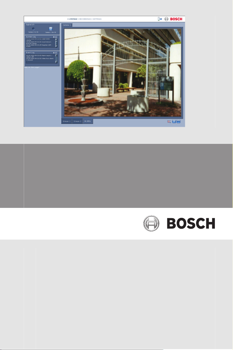
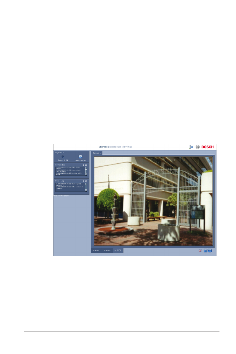
Live page
After the connection is established, the LIVE page is initially
displayed. It shows the live video image on the right of the
browser window. Depending on the configuration, various text
overlays may be visible on the live video image.
Other information may also be shown next to the live video
image. The items shown depend on the settings on the LIVE
Functions page.
Figure 3.1: Live page
3.1.1
Bosch Security Systems 2014.03 | v1.59 | AM18-Q0671
Image selection
Click a tab below the video image to display a camera image
stream.
14 en | Operation via the browser
Camera Browser
Interface
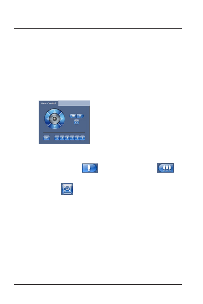
3.1.2
View Control ROI
When the Stream 2 encoder stream is set for Region of Interest
(ROI), a specific type of View Control panel is activated for
electronic pan, tilt and zoom control (E-PTZ).
Refer to Encoder Streams, page 52 for more information on
setting up Stream 2. (If dual ROI is available, open the camera in
a second browser window to set up the second ROI on Stream
2.)
Zoom
To zoom in on a region of the stream 2 image:
1. Click and hold to zoom in; click and hold to
zoom out.
2. Click
to see the full image.
Select an area
To select a particular region of the image:
1. Click and hold the arrows to move up and down, and from
side to side through the image.
2. Click and hold the center area to move in all directions.
Set positions
To store the current view:
1. Select a region of interest.
2. Click Set.
3. Click a number.
To display a pre-set region of interest, click one of the buttons
numbered one to six.
2014.03 | v1.59 | AM18-Q0671 Bosch Security Systems
Camera Browser
Interface
Operation via the browser | en 15
3.1.3
3.1.4
3.1.5
System Log / Event Log
The System Log field contains information about the operating
status of the camera and the connection.
Events such as the triggering or the end of alarms are shown in
the Event Log field.
1. To view, filter and save these messages to a file, click
in the top right-hand corner.
2. To clear the log, click in the top right-hand corner of
the relevant field.
Saving snapshots
Individual images from the video sequence that is currently
being shown can be saved in JPEG format on the computer's
hard drive.
4 Click the camera icon
The storage location depends on the configuration of the
camera.
to save a single image.
Recording video sequences
Sections of the video sequence that is currently being shown on
the LIVE page can be saved on the computer's hard drive. The
sequences are recorded at the resolution specified in the
encoder configuration. The storage location depends on the
configuration of the camera.
1. Click the recording icon
– Saving begins immediately. The red dot on the icon
indicates that a recording is in progress.
2. Click the recording icon again to stop recording.
Play back saved video sequences using the Player from
Bosch Security Systems.
Bosch Security Systems 2014.03 | v1.59 | AM18-Q0671
to record video sequences.
16 en | Operation via the browser
Camera Browser
Interface
3.1.6
3.1.7
3.1.8
Running recording program
The hard drive icon below the camera images on the LIVE page
changes during an automatic recording.
The icon lights up and displays a moving graphic
indicate a running recording. If no recording is taking place, a
static icon is displayed.
to
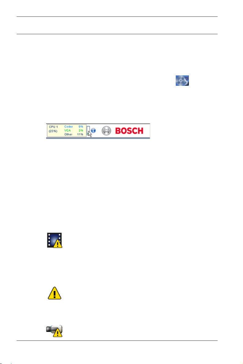
Processor load
When accessing the unit with a browser, the processor load and
network information is available in the upper right of the
window next to the Bosch logo.
Move the mouse cursor over the icons to display numerical
values. This information can help with problem solving or when
fine tuning the device.
Status icons
Various overlays in the video image provide important status
information. The overlays provide the following information:
Decoding error
The frame might show artefacts due to decoding errors. If other
frames reference this frame, they might also show decoding
errors but won’t be marked with the icon.
Alarm flag
Shown on a media item to indicate an alarm.
Communication error
2014.03 | v1.59 | AM18-Q0671 Bosch Security Systems
Camera Browser
Interface
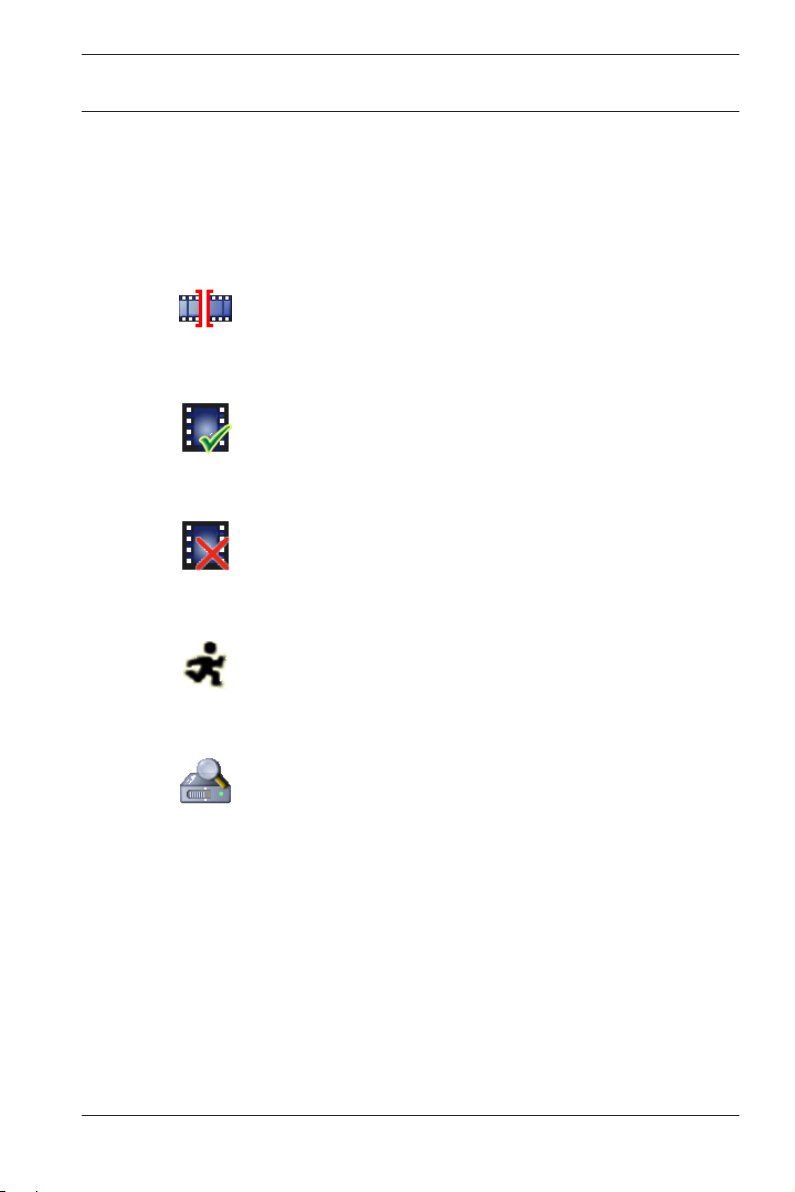
A communication error, such as a connection failure to the
storage medium, a protocol violation or a timeout, is indicated
by this icon. An automatic reconnection procedure is started in
the background to recover from this error.
Indicates a gap in the recorded video.
Watermark is set on media item.
Indicates that the watermark is not valid.
Operation via the browser | en 17
Gap
Watermark flag
Invalid watermark flag
Motion flag
Indicates that motion is dectected.
Storage discovery
Indicates that recorded video is being retrieved.
Bosch Security Systems 2014.03 | v1.59 | AM18-Q0671
18 en | Operation via the browser
Camera Browser
Interface
3.2
3.2.1
Playback
Click PLAYBACK from the Livepage or Settings page to view,
search or export recordings. This link is only visible if a direct
iSCSI or SD card has been configured for recording. (With VRM
recording this option is not active.)
A collapsible panel on the left of the display has four tabs:
– Track list
– Export
– Search
– Search results
Select the stream number to be shown in the Recording dropdown menu at the top of the window.
Selecting recordings for playback
To see all saved sequences:
1. Click the track list tab .
2. A list of tracks with a number assigned to each sequence is
displayed. Start time and stop time, recording duration,
number of alarms, and recording type are shown for each
track.
3. At the bottom of the window, select the maximum number
of tracks to be displayed in the list.
4. Use the arrow buttons at the bottom to browse the list.
5. To view tracks beginning from a particular time, enter the
time code and click Get Tracks.
6. Click a track. The playback for the selected sequence
starts.
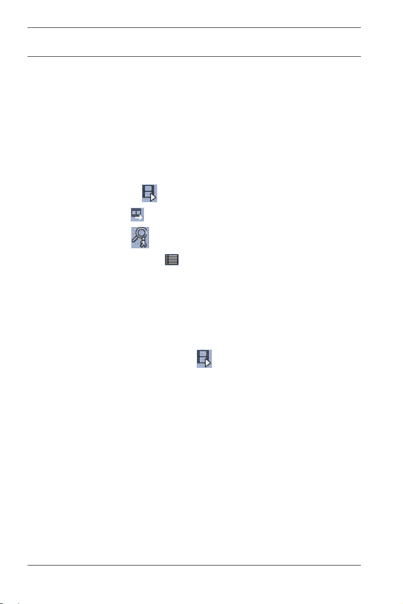
3.2.2
2014.03 | v1.59 | AM18-Q0671 Bosch Security Systems
Exporting tracks
1. Select a track in the track list.
Camera Browser
Interface
2. Click the export tab .
3. The start and stop time are filled-in for the selected track. If
4. Select a target.
5. Select the original or a condensed speed.
Operation via the browser | en 19
required, change the times.
3.2.3
3.2.4
6. Click the save icon
Note:
The target server address is set on the Network / Accounts
page.
.
Searching for tracks
1. Click the search tab .
2. Click one of the Search mode buttons to define the search
parameters.
3. To limit the search to a particular time range, enter the
start and stop times.
4. Click Start Search.
5. The results are shown in the search results tab .
6. Click a result to play it back.
7. Click the search tab
again to define a new search.
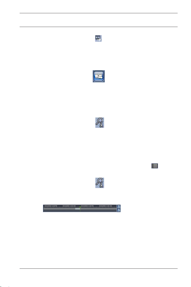
Controlling playback
The time bar below the video image allows quick orientation.
The time interval associated with the sequence is displayed in
the bar in gray. A green arrow above the bar indicates the
position of the image currently being played back within the
sequence.
The time bar offers various options for navigation in and
between sequences.
Bosch Security Systems 2014.03 | v1.59 | AM18-Q0671
en | Operation via the browser
20
– Change the time interval displayed by clicking the plus or
minus icons. The display can span a range from two months
to a few seconds.
– If required, click in the bar at the point in time at which the
playback should begin.
– Red bars indicate the points in time where alarms were
triggered.
To view the current live image, click Now.
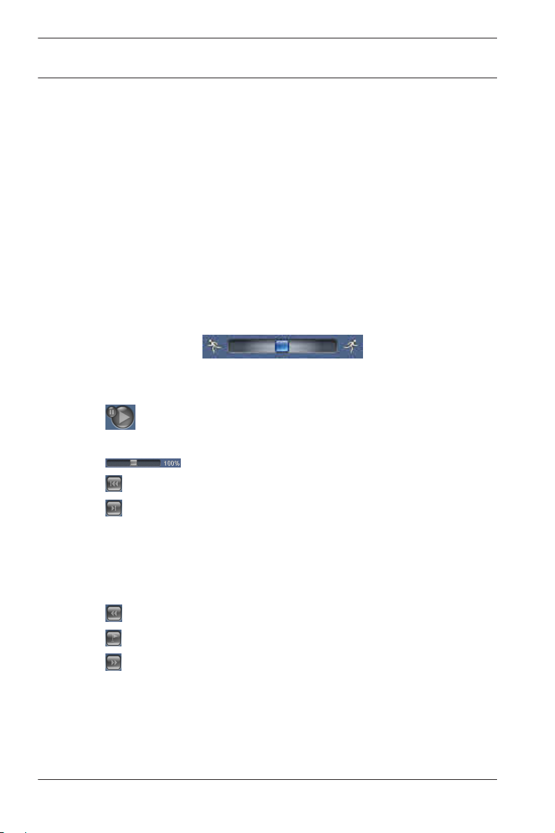
Controls
Control playback by means of the buttons below the video
image.
Use the jog dial to quickly scan the
sequences. The time code is displayed above it.
The buttons have the following functions:
Start/Pause playback
Select the playback speed using the speed regulator:
Camera Browser
Interface
Jump to start of active sequence or to previous sequence
Jump to start of the next video sequence in the list
Bookmarks
You can set markers in a sequence and jump to these directly.
These bookmarks are indicated as small yellow arrows above
the time interval. Use the bookmarks as follows:
Jump to the previous bookmark
Set bookmark
Jump to the following bookmark
Bookmarks are only valid while in the Recordings page; they are
not saved with the sequences. All bookmarks are deleted when
you leave the page.
2014.03 | v1.59 | AM18-Q0671 Bosch Security Systems

Camera Browser
Interface
Basic Mode | en 21
4
4.1
Basic Mode
Device Access
Assign a unique name to assist in identification. This name
simplifies the management of multiple devices in more extensive
systems.
The name is used for remote identification, for example, in the
event of an alarm. Choose a name that makes it as easy as
possible to identify the location unambiguously.
A password prevents unauthorized access to the device. You can
use different authorization levels to limit access.
Proper password protection is only guaranteed when all higher
authorization levels are also protected with a password.
Therefore, you always have to start from the highest
authorization level when assigning passwords.
You can define and change a password for each authorization
level if you are logged in as service or if the unit is not password
protected.
Enter the password for the appropriate authorization level here.
The maximum password text length is 19 characters and no
special characters are allowed.
The device has three authorization levels: service, user, and live.
– service is the highest authorization level. Entering the
correct password gives access to all the functions and
allows all configuration settings to be changed.
– user is the middle authorization level. At this level you can
operate the device, play back recordings, and also control
camera, for example, but you cannot change the
configuration.
– live is the lowest authorization level. At this level you can
only view the live video image and switch between the
different live image displays.
Bosch Security Systems 2014.03 | v1.59 | AM18-Q0671

22 en | Basic Mode
Define and change a separate password for each level. Enter the
password (19 characters maximum; no special characters) for
the selected level.
Re-enter the new password to ensure that there are no typing
mistakes.
Camera Browser
Interface
4.2
Date/Time
If there are multiple devices operating in the system or network,
it is important to synchronize their internal clocks. For example,
it is only possible to identify and correctly evaluate simultaneous
recordings when all devices are operating on the same time.
Device time, date and time zone are shown.
4 Click Sync to PC to apply the system time from your
computer to the device.
Note:
It is important that the date/time is correct for recording. An
incorrect date/time setting could prevent correct recording.
The unit can receive the time signal from a time server using
various time server protocols and then use it to set the internal
clock. The device polls the time signal automatically once every
minute.
Enter the IP address of a time server.
Select the protocol that is supported by the selected time
server. It is recommended to select the SNTP server protocol.
This protocol provides high accuracy and is required for special
applications and future function extensions.
Select Time server if the server uses the RFC 868 protocol.
4.3
2014.03 | v1.59 | AM18-Q0671 Bosch Security Systems
Network
The settings on these pages are used to integrate the device
into a network. Some changes only take effect after a reboot. In
this case Set changes to Set and Reboot.
1. Make the desired changes.
2. Click Set and Reboot.

Camera Browser
Interface
The device is rebooted and the changed settings are activated.
If the network has a DHCP server for the dynamic assignment of
IP addresses, select On to automatically accept the DHCPassigned IP address.
For certain applications, the DHCP server must support the
fixed assignment between IP address and MAC address, and
must be appropriately set up so that, once an IP address is
assigned, it is retained each time the system is rebooted.
IP address
Enter the desired IP address for the camera. The IP address
must be valid for the network.
Subnet mask
Enter the appropriate subnet mask for the set IP address.
Gateway address
For the device to establish a connection to a remote location in
a different subnet, enter the IP address of the gateway here.
Otherwise, this field can remain empty (0.0.0.0).
Basic Mode | en 23
4.4
4.5
Bosch Security Systems 2014.03 | v1.59 | AM18-Q0671
Encoder
Select a profile for encoding the video signal on stream 1 (this is
not a selection of the recording profile).
Pre-programmed profiles are available that give priority to
different parameters and they should be selected based on your
operating environment.
When a profile is selected, its details are displayed.
Recording
Record the images from the camera to a storage medium. For
long-term authoritative images, it is essential to use VRM or an
appropriately sized iSCSI system.
Storage medium
1. Select the required storage medium from the list.
2. Click Start to start recording or Stop to end recording.

24 en | Basic Mode
Camera Browser
Interface
4.6
System Overview
This page provides general information on the hardware and
firmware system, including version numbers. No items can be
changed on this page but they can be copied for information
purposes when troubleshooting.
2014.03 | v1.59 | AM18-Q0671 Bosch Security Systems

Camera Browser
Interface
General settings | en 25
5
5.1
5.1.1
General settings
Identification
Naming
Assign a unique name to assist in identification. This name
simplifies the management of multiple devices in more extensive
systems.
The name is used for remote identification, for example, in the
event of an alarm. Choose a name that makes it as easy as
possible to identify the location unambiguously.
You can use additional lines to enter kanji characters.
1. Click the + sign to add a new line
2. Click the icon next to the new line. A window with a
character map opens.
3. Click the required character. The character is inserted into
the Result field.
4. In the character map, click the << and >> icons to move
between the different pages of the table, or select a page
from the list field.
5. Click the < icon to the right of the Result field to delete the
last character, or click the X icon to delete all characters.
6. Click the OK button to apply the selected characters to the
new line of the name. The window closes.
5.1.2
5.1.3
Bosch Security Systems 2014.03 | v1.59 | AM18-Q0671
ID
Each device should be assigned a unique identifier that can be
entered here as an additional means of identification.
iSCSI Initiator extension
Add text to an initiator name to make identification easier in
large iSCSI systems. This text is added to the initiator name,
separated from it by a full stop. (You can see the initiator name
in the System Overview page.)

26 en | General settings
Camera Browser
Interface
5.2
Password
A password prevents unauthorized access to the device. You can
use different authorization levels to limit access.
Proper password protection is only guaranteed when all higher
authorization levels are also protected with a password.
Therefore, you always have to start from the highest
authorization level when assigning passwords.
You can define and change a password for each authorization
level if you are logged in as service or if the unit is not password
protected.
Enter the password for the appropriate authorization level here.
The maximum password text length is 19 characters and no
special characters are allowed.
The device has three authorization levels: service, user, and live.
– service is the highest authorization level. Entering the
correct password gives access to all the functions and
allows all configuration settings to be changed.
– user is the middle authorization level. At this level you can
operate the device, play back recordings, and also control
camera, for example, but you cannot change the
configuration.
– live is the lowest authorization level. At this level you can
only view the live video image and switch between the
different live image displays.
5.2.1
5.2.2
2014.03 | v1.59 | AM18-Q0671 Bosch Security Systems
Enter Password
Define and change a separate password for each level. Enter the
password (19 characters maximum; no special characters) for
the selected level.
Confirm password
Re-enter the new password to ensure that there are no typing
mistakes.

Camera Browser
Interface
General settings | en 27
5.3
5.3.1
5.3.2
Date/Time
Date format
Select the required date format.
Device date / Device time
If there are multiple devices operating in your system or
network, it is important to synchronize their internal clocks. For
example, it is only possible to identify and correctly evaluate
simultaneous recordings when all devices are operating on the
same time.
1. Enter the current date. Since the device time is controlled
by the internal clock, it is not necessary to enter the day of
the week – it is added automatically.
2. Enter the current time or click Sync to PC to apply the
system time from your computer to the device.
Note:
It is important that the date/time is correct for recording. An
incorrect date/time setting could prevent correct recording.
5.3.3
5.3.4
Bosch Security Systems 2014.03 | v1.59 | AM18-Q0671
Device time zone
Select the time zone in which the system is located.
Daylight saving time
The internal clock can switch automatically between normal and
daylight saving time (DST). The unit already contains the data
for DST switch-overs for many years in advance. If the date, time
and zone have been set up correctly, a DST table is
automatically created.
If you decide to create alternative daylight saving time dates by
editing the table, note that values occur in linked pairs (DST
start and end dates).

28 en | General settings
First, check the time zone setting. If it is not correct, select the
appropriate time zone and click Set.
1. Click Details to edit the DST table.
2. Select the region or the city which is closest to the
system's location from the list box below the table.
3. Click Generate to fill the table with the preset values from
the unit.
4. Click one of the entries in the table to make changes. The
entry is highlighted.
5. Click Delete to remove the entry from the table.
6. Choose other values from the list boxes under the table, to
change the selected entry. Changes are immediate.
7. If there are empty lines at the bottom of the table, for
example after deletions, add new data by marking the row
and selecting values from the list boxes.
8. When finished, click OK to save and activate the table.
Camera Browser
Interface
5.3.5
Time server IP address
The unit can receive the time signal from a time server using
various time server protocols and then use it to set the internal
clock. The device polls the time signal automatically once every
minute.
Enter the IP address of a time server.
5.3.6
Time server type
Select the protocol that is supported by the selected time
server. It is recommended to select the SNTP server protocol.
This protocol provides high accuracy and is required for special
applications and future function extensions.
Select Time server if the server uses the RFC 868 protocol.
2014.03 | v1.59 | AM18-Q0671 Bosch Security Systems

Camera Browser
Interface
General settings | en 29
5.4
5.4.1
5.4.2
5.4.3
Display Stamping
Various overlays or stamps in the video image provide important
supplementary information. These overlays can be enabled
individually and arranged on the image in a clear manner.
Camera name stamping
Select the position of the camera name overlay in the dropdown box. It can be displayed at the Top, at the Bottom, or at a
position of choice using the Custom option, or it can be set to
Off for no overlay information.
If the Custom option is selected, enter values in the X and Y
position fields.
Time stamping
Select the position of the time and date overlay in the dropdown box. It can be displayed at the Top, at the Bottom, or at a
position of choice using the Custom option, or it can be set to
Off for no overlay information.
If the Custom option is selected, enter values in the X and Y
position fields.
Display milliseconds
If necessary, display milliseconds for Time stamping. This
information can be useful for recorded video images; however, it
does increase the processor's computing time. Select Off if
displaying milliseconds is not needed.
5.4.4
Bosch Security Systems 2014.03 | v1.59 | AM18-Q0671
Alarm mode stamping
Select On in the drop-down box for a text message to be
displayed in the event of an alarm. It can be displayed at a
position of choice using the Custom option, or it can be set to
Off for no overlay information.
If the Custom option is selected, enter values in the X and Y
position fields.

30 en | General settings
Camera Browser
Interface
5.4.5
5.4.6
5.4.7
5.5
Alarm message
Enter the message to be displayed on the image in the event of
an alarm. The maximum text length is 31 characters.
Transparent stamping
Check this box to make the stamp on the image transparent.
Video authentication
Select a method for verifying the integrity of the video in the
Video authentication drop-down box.
If you select Watermarking all images are marked with an icon.
The icon indicates if the sequence (live or saved) has been
manipulated.
If you want to add a digital signature to the transmitted video
images to ensure their integrity, select one of the cryptographic
algorithms for this signature.
Enter the interval (in seconds) between insertions of the digital
signature.
GB/T 28181
This page allows you to set the parameters for conformance to
the GB/T 28181 national standard “Security and protection
video monitoring network system for information transport,
switch and control”.
2014.03 | v1.59 | AM18-Q0671 Bosch Security Systems
 Loading...