

Bosch MX775I Specsheet

Intrusion Alarm Systems | MX775i Multiplex PIR Intrusion Detector
MX775i Multiplex PIR Intrusion Detector
www.boschsecurity.com
u Interchangeable, pointable mirrors
u Selectable sensitivity
u Built-in tamper switch
The MX775i is a PIR intrusion detector that provides a
variety of coverage patterns through the use of
interchangeable mirrors and the choice of mirror angle
settings. It is designed to be surface or corner
mounted, but can be mounted with any of three
optional brackets. This provides further flexibility in
aiming the detector. It is designed to connect to the
Multiplex Bus of a control panel and optionally to an
auxiliary 12 VDC power source. It is compatible with
the DS7400Xi Series Control Panels with a DS7430 or
DS7436 Multiplex Expansion Module or with GV2 and
G Series Control Panels with a D8125MUX Module
installed.
Notice
The DS7400 and DS7400Xi require ROM version
1.07 or greater.
Functions
Interchangeable, Pointable Mirrors
The detector comes with a standard broad pattern
mirror and two optional mirrors are available: a longrange pattern mirror and a barrier pattern mirror. To
change the mirror, pull it out from its resting grooves.
To adjust the mirror vertically (from +1° to -18°) slide
the mirror forward or back. To adjust the mirror
horizontally (±10°) rock the mirror from side to side.
Three Sensitivity Settings
Selectable for Standard, Intermediate or High:
• Standard: Recommended setting for maximum false
alarm immunity. Tolerates environment extremes on
this setting. Not recommended for Long Range or
Barrier type patterns. The detector is shipped in
Standard Sensitivity mode.
• Intermediate: Recommended setting for any location
where an intruder is expected to cover only a small
portion of the protected area. Tolerates normal
environments on this setting. This setting will improve
your intruder catch performance.
• High: Fast response to intruder signals. For use in
quiet environments where thermal and illumination
transients are not anticipated.
Internal Tamper Switch
The internal tamper switch sends a signal to the
control panel's Multiplex Bus for display at the
keypads when the detector's cover is removed.
Mounting
Height
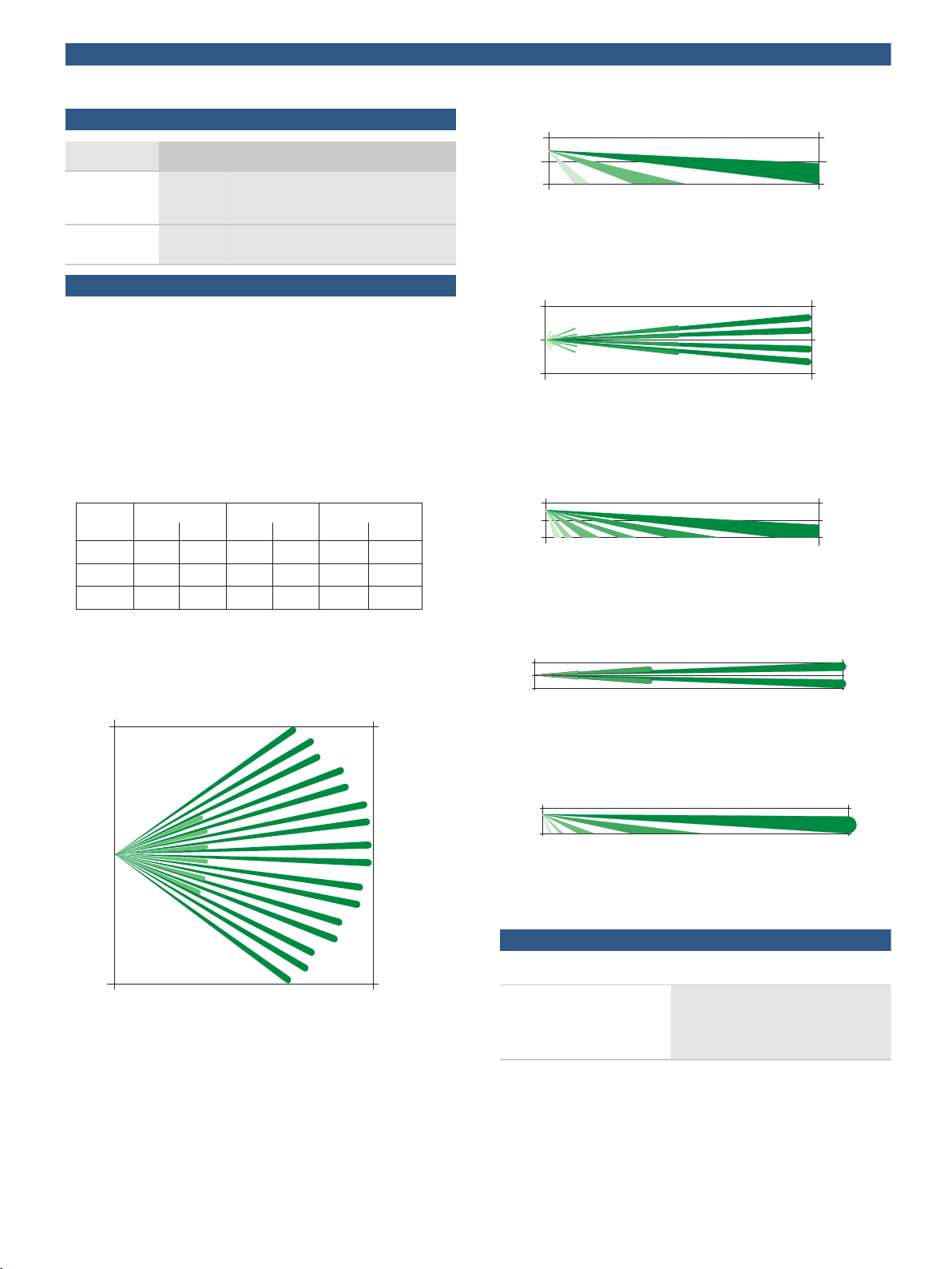
30 (9) 50 (15) 80 (25)
120 (36)
50 (15)
80 (25)
6.5 (2.0)
7. 5 (2.3)
8.5 (2.6)
Broad Barrier
Long-Range
Height and Range listed in feet (meters)
-6˚
-8˚
-9˚
-5˚-6˚
-7˚
-3˚
-5˚
-6˚
-2˚
-3˚
-4˚
-2˚
-3˚
-4˚
-1˚
-2˚
-2˚
0 ft
0 m
0 ft
7.5 m
25 ft
25 ft
50 ft
7.5 m
15 m
0 m
0 m
0 ft
0 ft
0 m
3 m
15 m
50 ft
10 ft
0 ft
0 m
0 ft
0 m
10 f t
10 f t
80 f t
25 m
3 m
3 m
0 ft
0 m
0 ft
0 m
5 ft
10 ft
80 ft
3 m
25 m
0 m
0 ft
0 m
0 ft
5 ft
5 ft
120 ft
36 m
1.5 m
1.5 m
0 ft
0 m
0 ft
0 m
3 m
10 ft
120 ft
36 m
2 | MX775i Multiplex PIR Intrusion Detector
Certifications and approvals
Region Certification
Europe CE 2004/108/EC EMC Directive (EMC);
2006/95/EC Low-Voltage Directive
(LVD) [MX775i]
USA UL ANSR: Intrusion Detection Units
(UL639)
Installation/configuration notes
Wiring
Do not use shielded cable. Use wire that is no smaller
than 0.8 mm (22 AWG) to connect the detector to the
control panel.
Coverage
The recommended mounting height range is 2 m to
2.6 m (6.5 ft to 8.5 ft). Misalignment of the detector
when using an optional mounting bracket may reduce
range.
The range is variable depending on the vertical angle
setting of the mirror. The chart indicates vertical angle
settings for the desired mounting height, mirror type,
and range.
Side View
Standard Broad Coverage: 9 m to 15 m x 15 m
(30 ft to 50 ft x 50 ft)
Top View
Optional Barrier Coverage: 15 m to 25 m x 5 m
(50 ft to 80 ft x 16 ft)
Side View
Optional Barrier Coverage: 15 m to 25 m x 5 m
(50 ft to 80 ft x 16 ft)
Top View
Standard Broad Coverage: 9 m to 15 m x 15 m
(30 ft to 50 ft x 50 ft)
Top View
Optional Long Range Coverage: 25 m to 36 m x 3 m
(80 ft to 120 ft x 10 ft)
Side View
Optional Long Range Coverage: 25 m to 36 m x 3 m
(80 ft to 120 ft x 10 ft)
Technical specifications
Environmental Considerations
Temperature (Operating): -29°C to +49°C (-20°F to +120°F). For
UL Listed Requirements, the
temperature range is 0°C to +49°C
(+32°F to +120°F).
 Loading...