

Bosch MX30E Operating/safety Instructions Manual
IMPORTANT: IMPORTANT : IMPORTANTE:
Read Before Using Lire avant usage Leer antes de usar
For English Version Version française Versión en español
See page 2 Voir page 20 Ver la página 38
Operating/Safety Instructions
Consignes de fonctionnement/sécurité
Instrucciones de funcionamiento y seguridad
1-877-BOSCH99 (1-877-267-2499) www.boschtools.com
Call Toll Free for
Consumer Information
& Service Locations
Pour obtenir des informations
et les adresses de nos centres
de service après-vente,
appelez ce numéro gratuit
Llame gratis para
obtener información
para el consumidor y
ubicaciones de servicio
MX30E
DM 2610033449 02-14_MX30E 2/11/14 12:54 PM Page 1

-2-
Work area safety
Keep work area clean and well lit. Cluttered
or dark areas invite accidents.
Do not operate power tools in explosive
atmospheres, such as in the presence of
flammable liquids, gases or dust. Power
tools create sparks which may ignite the dust
or fumes.
Keep children and bystanders away while
operating a power tool. Distractions can
cause you to lose control.
Electrical safety
Power tool plugs must match the outlet.
Never modify the plug in any way. Do not
use any ad apter p lugs w ith ea r thed
(grounded) power tools. Unmodified plugs
and matching outlets will reduce risk of electric
shock.
Avoid body contact with earthed or grounded
surfaces such as pipes, radiators, ranges
and refrigerators. There is an increased risk
of electric shock if your body is earthed or
grounded.
Do not expose power tools to rain or wet
conditions. Water entering a power tool will
increase the risk of electric shock.
Do not abuse the cord. Never use the cord
for carrying, pulling or unplugging the power
tool. Keep cord away from heat, oil, sharp
edges or moving parts. Damaged or entangled
cords increase the risk of electric shock.
When operating a power tool outdoors,
use an extension cord suitable for outdoor
use. Use of a cord suitable for outdoor use
reduces the risk of electric shock.
If operating a power tool in a damp location
is unavoidable, use a Ground Fault Circuit
Interrupter (GFCI) protected supply. Use of
an GFCI reduces the risk of electric shock.
Personal safety
Stay alert, watch what you are doing and
us e common sense when operatin g a
power tool. Do not use a power tool while
you are tired or under the influence of drugs,
alcohol or medication. A moment of inattention
while operating power tools may result in
serious personal injury.
Use personal protective equipment. Always
wear eye protection. Protective equipment
such as dust mask, non-skid safety shoes, hard
hat, or hearing protection used for appropriate
conditions will reduce personal injuries.
Prevent unintentional starting. Ensure the
sw itch is in the off -position before
connecting to power source and / or battery
pa ck, picking up o r carrying the tool.
Carrying power tools with your finger on the
switch or energizing power tools that have the
switch on invites accidents.
Remove any adjusting key or wrench before
turning the power tool on. A wrench or a
key left attached to a rotating part of the power
tool may result in personal injury.
Do not overreach. Keep proper footing and
balance at all times. This enables better
control of the power tool in unex pected
situations.
Dress properly. Do not wear loose clothing
or jewelry. Keep your hair, clothing and
gloves away from moving parts. Loose
clothes, jewelry or long hair can be caught in
moving parts.
If devices are provided for the connection
of dust extraction and collection facilities,
ensure these are connected and properly
used. Use of dust collection can reduce dust-
related hazards.
Power tool use and care
Do not force the power tool. Use the correct
power tool for your application. The correct
power tool will do the job better and safer at
the rate for which it was designed.
Do not use the power tool if the switch does
not turn it on and off. Any power tool that
can not be contr olled with the switch is
dangerous and must be repaired.
Read all safety warnings and all instructions. Failure to follow the warnings
and instructions may result in electric shock, fire and/or serious injury.
SAVE ALL WARNINGS AND INSTRUCTIONS FOR FUTURE REFERENCE
The term “power tool” in the warnings refers to your mains-operated (corded) power tool or
battery-operated (cordless) power tool.
!
WARNING
General Power Tool Safety Warnings
DM 2610033449 02-14_MX30E 2/11/14 12:54 PM Page 2

-3-
Disconnect the plug from the power source
and/or the battery pack from the power tool
before making any adjustments, changing
accessories, or storing power tools. Such
preventive safety measures reduce the risk of
s
tarting the power tool accidentally.
Store idle power tools out of the reach of
children and do not allow persons unfamiliar
with the power tool or these instructions to
operate the power tool. Power tools are
dangerous in the hands of untrained users.
Maintain power tools. Check for misalignment
or binding of moving parts, breakage of
parts and any other condition that may
affect the power tool’s operation. If damaged,
have the power tool repaired before use.
Man y a ccide nts are cau s ed by poor l y
maintained power tools.
Keep cutting tools sharp and clean. Properly
maintained cutting tools with sharp cutting
edges are less likely to bind and are easier to
control.
Use the power tool, accessories and tool
bits etc. in accordance with these instructions,
taking into account the working conditions
and the work to be performed. Use of the
power tool for operations different from those
intended could result in a hazardous situation.
Service
Have your power tool serviced by a qualified
rep air per son usi ng only identi cal
replacement parts. This will ensure that the
safety of the power tool is maintained.
Safety Rules for Oscillating Tools
Hold power tool by insulated gripping
surfaces when performing an operation
where the cutting tool may contact hidden
wiring or its own cord. Contact with a "live"
wire will make exposed metal parts of the tool
"live" and shock the operator.
Use clamps or another practical way to
secure and support the workpiece to a
stable platform. Holding the work by hand or
against your body leaves it unstable and may
lead to loss of control.
Use a metal detector to determine if there
are gas or water pipes hidden in the work
area or call the local utility company for
assistance before beginning the operation.
Striking or cutting into a gas line will result in
explosion. Water entering an electrical device
may cause electrocution.
Always hold the tool firmly with both hands
for maximum control. Keep proper footing
and balance at all times. This enables better
control of t he powe r tool in un expe cted
situations.
Keep hands away from cutting area. Do
not reach under the material being cut. The
proximity of the blade to your hand is hidden
from your sight.
Do not use dull or damaged blades. Bent
blade can break easily or cause kickback.
Exercise extreme caution when handling
the accessories. The accessories are very
sharp.
Wear protective gloves when changing
cutting accessories. Accessories become
hot after prolonged usage.
Use thick cushioned gloves and limit the
exposure time by taking frequent rest
periods. Vibration caused by the tool may be
harmful to the hands and arms.
Before scraping, check workpiece for nails.
If there are nails, either remove them or set
them well below intended finished surface.
Striking a nail with accessory edge could
cause the tool to jump.
Do not wet sand with this tool. Liquids
entering the motor housing is an electrical
shock hazard.
Never work in area which is soaked with a
li quid , such as a s olve nt or water, or
dampened such as newl y app lied
wallpaper. There is an electrical shock
hazard when working in such conditions with a
power tool and heating of the liquid caused by
scraping action may cause harmful vapors to
be emitted from workpiece.
Always wear eye protection and a dust
mask for dusty applications and when
DM 2610033449 02-14_MX30E 2/11/14 12:54 PM Page 3

-4-
GFCI and personal protection devices like
electrician’s rubber gloves and footwear will
further enhance your personal safety.
Do not use AC only rated tools with a DC
power supply. While the tool may appear to
work, the electrical components of the AC
rated tool are likely to fail and create a hazard
to the operator.
Keep handles dry, clean and free from oil
and grease. Slippery hands cannot safely
control the power tool.
Develop a periodic maintenance schedule
for your tool. When cleaning a tool be
careful not to disassemble any portion of
th e tool since in ternal wires may be
misplaced or pinched or safety guard return
sp rings may be imprope rly mounted.
Certain cleaning agents such as gasoline,
carbon tetrachloride, ammonia, etc. may
damage plastic parts.
Risk of injury to user. The power cord must only
be serviced by a Bosch Factory Service Center
or Autho rized Bosch Service Station.
Some dust created by power
sanding, sawing, grinding,
drilling, and other construction activities
contains chemicals known to cause cancer,
birth defects or other reproductive harm.
Some examples of these chemicals are:
• Lead from lead-based paints,
• Crystalline silica from bricks and cement and
other masonry products, and
• Arsenic and chromium from chemically-
treated lumber.
You r ri sk from t hese expos ures varies ,
depending on how often you do this type of
work. To reduce your exposure to these
chemicals: work in a well ventilated area, and
work with approved safety equipment, such as
those dust masks that are specially designed
to filter out microscopic particles.
Additional Safety Warnings
!
WARNING
sanding overhead. Sanding particles can be
absorbed by your eyes and inhaled easily
and may cause health complications.
Use special precautions when sanding
chemically pressure treated lumber, paint
that may be lead based, or a ny other
materials that may contain carcinogens. A
suitable breathing respirator and protective
clothing must be worn by all persons entering
the work area. Work area should be sealed by
plastic sheeting and persons not protected
should be kept out until work area is thoroughly
cleaned.
Do not use sandpaper intended for larger
sanding pads. Larger sandpaper will extend
beyond the sanding pad causing snagging,
tearing of the paper or kick-back. Extra paper
extending beyond the sanding pad can also
cause serious lacerations.
DM 2610033449 02-14_MX30E 2/11/14 12:54 PM Page 4

-5-
IMPORTANT: Some of the following symbols may be used on your tool. Please study them
and learn their meaning. Proper interpretation of these symbols will allow you to operate the
tool better and safer.
Symbol Name Designation/Explanation
V Volts Voltage (potential)
A Amperes Current
Hz Hertz Frequency (cycles per second)
W Watt Power
kg Kilograms Weight
min Minutes Time
s Seconds Time
Diameter Size of drill bits, grinding wheels, etc.
n
0
No load speed Rotational speed, at no load
n Rated speed Maximum attainable speed
.../min Revolutions or reciprocation Revolutions, strokes, surface speed,
per minute orbits etc. per minute
0 Off position Zero speed, zero torque...
1, 2, 3, ... Selector settings Speed, torque or position settings.
I, II, III, Higher number means greater speed
Infinitely variable selector with off Speed is increasing from 0 setting
Arrow Action in the direction of arrow
Alternating current Type or a characteristic of current
Direct current Type or a characteristic of current
Alternating or direct current Type or a characteristic of current
Class II construction Designates Double Insulated
Construction tools.
Earthing terminal Grounding terminal
Warning symbol Alerts user to warning messages
Li-ion RBRC seal Designates Li-ion battery recycling
program
Ni-Cad RBRC seal Designates Ni-Cad battery recycling
program
Read manual symbol Alerts user to read manual
Wear eye protection symbol Alerts user to wear eye protection
Symbols
DM 2610033449 02-14_MX30E 2/11/14 12:54 PM Page 5

-6-
This symbol designates that this tool is listed by Underwriters Laboratories.
This symbol designates that this tool is listed by the Canadian Standards
Association.
This symbol designates that this tool is listed by the Canadian Standards
Association, to United States and Canadian Standards.
This symbol designates that this tool complies to NOM Mexican Standards.
This symbol designates that this tool is listed by the Intertek Testing
Services, to United States and Canadian Standards.
Symbols (continued)
IMPORTANT: Some of the following symbols may be used on your tool. Please study them
and learn their meaning. Proper interpretation of these symbols will allow you to operate the
tool better and safer.
This symbol designates that this component is recognized by Underwriters
Laboratories.
This symbol designates that this tool is listed by Underwriters Laboratories,
to United States and Canadian Standards.
DM 2610033449 02-14_MX30E 2/11/14 12:54 PM Page 6
-7-
Functional Description and Specifications
Disconn ect the plu g from the powe r source be fore mak ing any
assembly, adjustments or changing accessories. Such preventive safety
measures reduce the risk of starting the tool accidentally.
!
WARNING
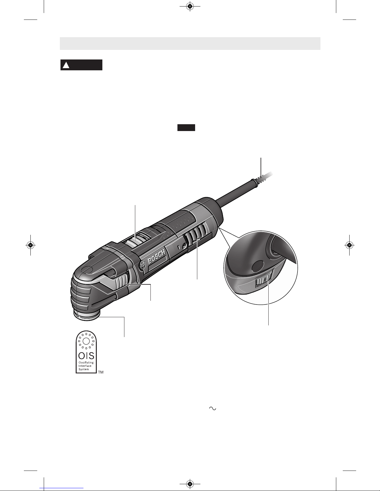
NOTE: For tool specifications refer to the nameplate on your tool.
Multi-X Oscillating Power Tool
Model number MX30E
No load speed n
0
8,000-20,000/min
Voltage rating 120 V 60 Hz
FIG. 1
OIS
ACCESSORY
HOLDER
SLIDE
"ON/OFF"
SWITCH
VENTILATION
OPENINGS
VARIABLE SPEED
CONTROL DIAL
POWER
CORD
ACCESSORY
CHANGE LEVER
DM 2610033449 02-14_MX30E 2/11/14 12:54 PM Page 7
-8-
Disconnect the plug from
the power source before
making any assembly, adjustments or
changing accessories. Such preventive
safety measures reduce the risk of starting the
tool accidentally.
For a ll work o r w hen
changing accessories
always wear protective gloves. Such
preventive safety measures reduce the risk of
injury from sharp edges of the accessories.
Application tools can become very hot while
working. Danger of burns!
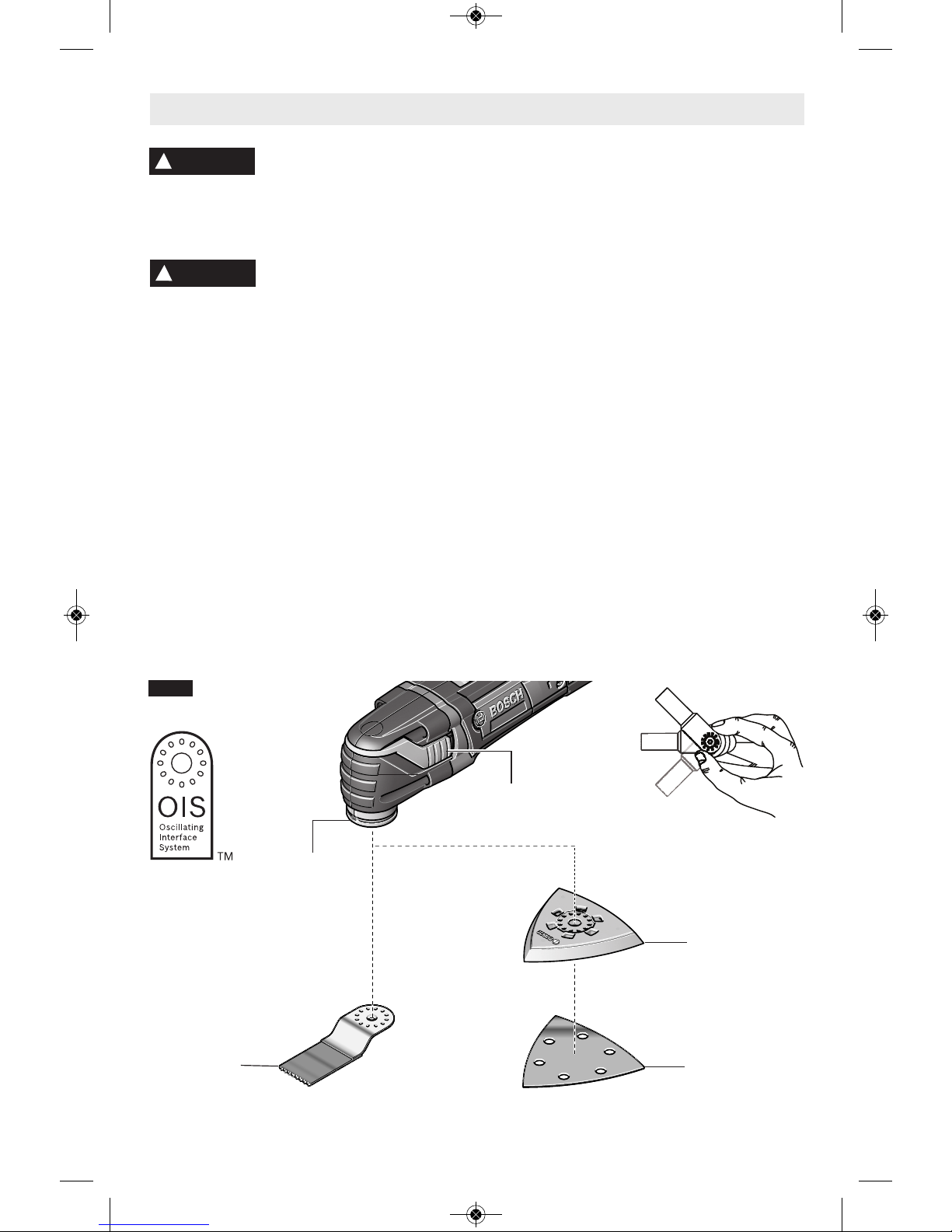
INSTALLING AND REMOVING
ACCESSORIES
1. Open accessory change lever (Fig. 2).
2. Clean OIS accessory holder and accessory
with a clean cloth.
3. Place the accessory onto the OIS accessory
holder making sure the accessory engages
all pins in the holder and the accessory is
flush aganist the OIS accessory holder.
4. Close accessory change lever (Fig. 2).
5. To remove accessory, open accessory
change lever and take accessory off of OIS
accessory holder.
NOTE: Some accessories, such as scrapers or
blades, may be mounted either straight on the
tool, or at an angle to enhance usability (Fig. 2).
INSTALLING AND REMOVING
SANDING SHEETS
Your backing pad uses hook-and-loop backed
accessories, which firmly grip the backing pad
when applied with moderate pressure.
1. Align the sanding sheet and press it onto the
sanding plate by hand.
2. Firmly press the power tool with the sanding
sheet against a flat surface and briefly
switch the power tool on. This will promote
good adhesion and helps to prevent
premature wear.
3. To change, merely peel off the old sanding
sheet, remove dust from the backing pad if
necessary, and press the new sanding
sheet in place.
After considerable service the backing pad
surface will become worn, and the backing pad
must be replaced when it no longer offers a firm
grip. If you are experiencing premature wear
out of the backing pad facing, decrease the
amount of pressure you are applying during
operation of the tool.
For maximum use of abrasive, rotate pad 120
degrees when tip of abrasive becomes worn.
Assembly
!
WARNING
!
WARNING
RUBBER
BACKING PAD
SANDING
SHEET
OIS
ACCESSORY
HOLDER
PLUNGE CUT
BLADE
FIG. 2
ACCESSORY
CHANGE LEVER
DM 2610033449 02-14_MX30E 2/11/14 12:54 PM Page 8
-9-
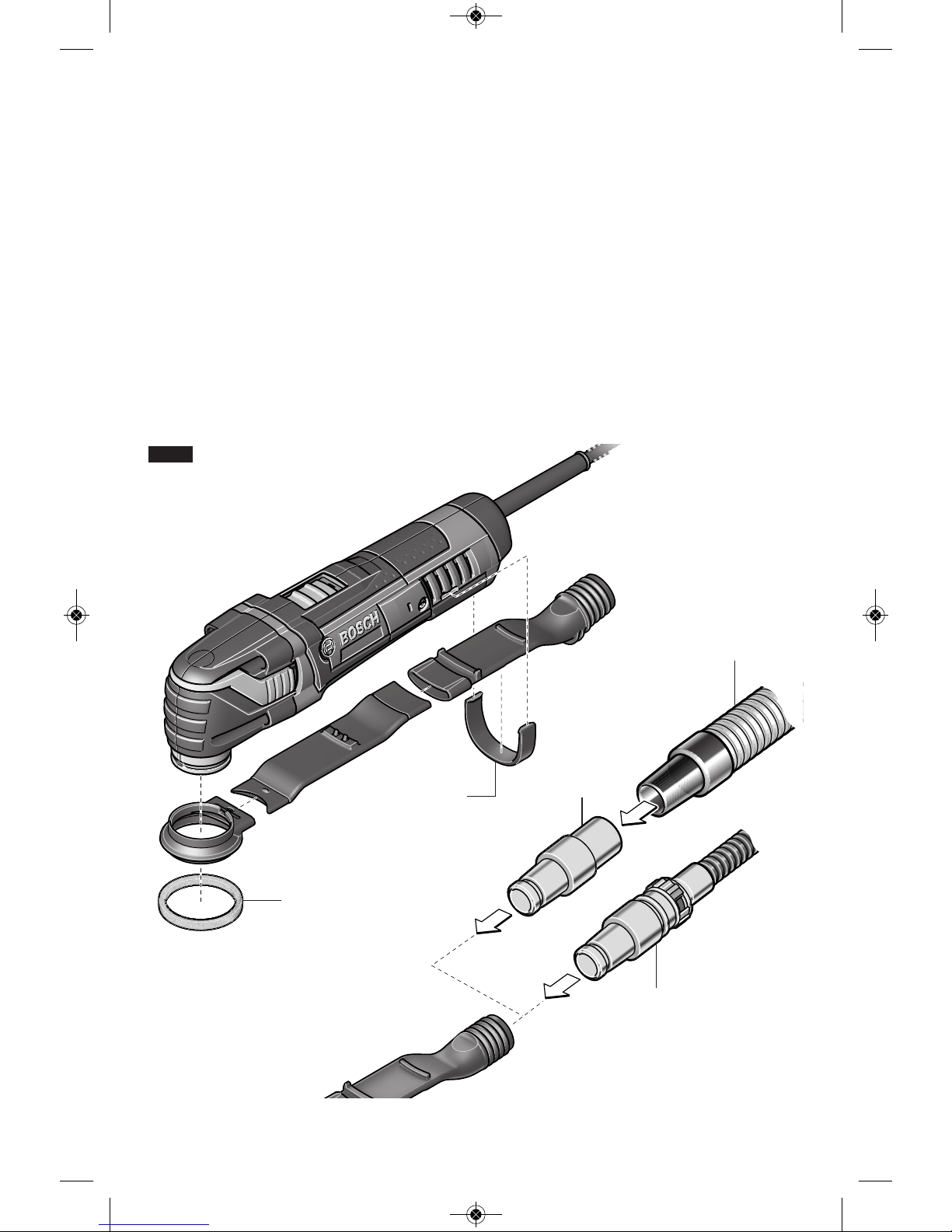
CONNECTING THE DUST EXTRACTION
ATTACHMENT
The opti onal O SC00 3 dust extra ctio n
attachment (sold separately) is only for use
when sanding. It is not designed for use when
c
utting, scraping or grinding.
Assemble and attach the parts of the dust
extraction as shown in figure 3.
1. Befo re moun ting the dus t e xtra ctio n
attachment pieces, remove any accessory
that is attached to the tool.
2. Make sure that the dust extraction hood's
felt ring is undamaged and faces tightly
against the sand ing plate. Replace a
damage felt ring immediately.
3. Attach the two parts of the dust extraction
tube to each other and to the dust extraction
hood.
4. Position the assembled dust extraction
attachment onto the tool over the accessory
attachment area.
5
. Secure the assembled dust extraction tube
onto the tool using the retaining clip as
shown in figure 3.
6. Attach the rubber backing pad and sanding
sheet.
7. Place a vacuum hose or vacuum cleaner
hose adapter onto the dust extraction tube.
8. Connect the vacuum hose to a vacuum
cleaner.
The vacuum cleaner must be suitable for the
material being worked. When vacuuming dry
dust that is especially detrimental to health or
carcinogenic, use a vacuum cleaner that is
specifically intended for that purpose.
FELT RING
RETAINING
CLIP
VAC024
1-1/4”
OR
1-1/2” HOSE
FIG. 3
BOSCH
VACUUM
HOSE
DM 2610033449 02-14_MX30E 2/11/14 12:54 PM Page 9
-10-
Operating Instructions
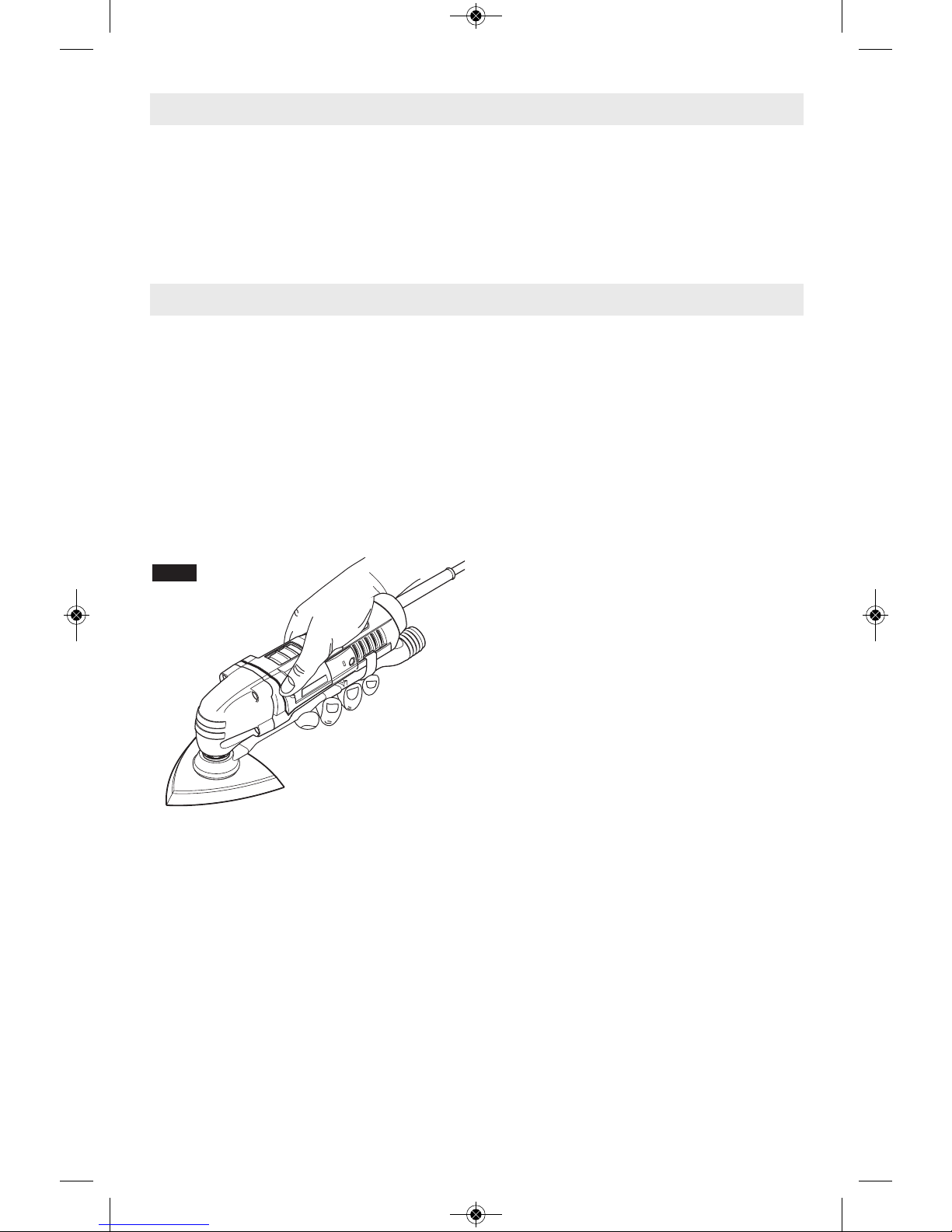
LEARNING TO USE THE TOOL
Getting the most out of your oscillating tool is a
matter of learning how to let the speed and the
feel of the tool in your hands work for you.
The first step in learning to use the tool is to
get the “feel” of it. Hold it in your hand and feel
its weight and balance (Fig. 4). Depending on
the application, you will need to adjust your
hand position to achieve optimum comfort and
control. The unique comfort grip on the body of
the tool allows for added comfort and control
during use.
When holding tool, do not cover the air vents
with your hand. Blocking the air vents could
cause the motor to overheat.
IMPORTANT! Practice on scrap material first
to see how th e t ool’s high-speed acti on
performs. Keep in mind that your tool will
perform best by allowing the speed, along with
the correct accessory, do the work for you. Be
careful not to apply too much pressure.
Instead, lower the oscillating accessory lightly
to the work surface and allow it to touch the
point at which you want to begin. Concentrate
on guiding the tool over the work using very
little pressure from your hand. Allow the
accessory to do the work.
Usually it is better to make a series of passes
with the tool rather than to do the entire job
with one pass. To make a cut, for example,
pass the tool back and forth over the work. Cut
a little material on each pass until you reach
the desired depth.
SLIDE "ON/OFF" SWITCH
The tool is switched "ON" by the slide switch
located on the topside of the motor housing
(Fig. 1).
TO TURN THE TOOL "ON" slide the switch
button forward to the “I” .
TO TURN THE TOOL "OFF" slide the switch
button backward the “0” .
ELECTRONIC FEEDBACK
Your tool is equipped with a n int erna l
electronic feedback system that provides a
“soft start”, which will reduce the stresses that
occur from a high torque start. The system
also helps to keep the preselected speed
virtually constant between no-load and load
conditions.
VARIABLE SPEED DIAL
This tool is equipped with a variable speed
dial. The speed may be controlled during
operation by presetting the dial in any one of
six positions (Fig. 1).
OPERATING SPEEDS
The Bosch Multi-X has a high oscillating
motion of 8,000 - 20,000 /min (OPM). The
high speed motion allows the Bosch Multi-X
to achieve with ex cellent results. The
oscillating motion allows the dust to fall to the
surface rather than slinging particles into the
air.
To achieve the best results when working
with different materials, set the variable
speed control to suit the job (See Speed
Chart on Page 12 for guidance) . To select
the right speed for the accessory in use,
practice with scrap material first.
FIG. 4
INTENDED USE
This Bosch Multi- X Os c i l l a ting Tool is
intended for dry sanding of surfaces, corners,
edges, for scraping, for sawing soft metals,
wood and plastic components, and for grout
rem o val u sing t he a p plicab l e to o ls a n d
accessories recommended by Bosch.
Introduction
DM 2610033449 02-14_MX30E 2/11/14 12:54 PM Page 10

-11-
NOTE: Speed is affected by voltages
changes. A reduced incoming voltage will
slow the OPM of the tool, especially at the
lowest setting. If your tool appears to be
running slowly, increase the speed setting
a
ccordingly. The tool may not start at the
lowest switch setting in areas where outlet
voltage is less than 120 volts. Simply move
the speed setting to a higher position to
begin operation.
The variable spee d contr ol s etti ngs are
marked on t h e speed control d i a l . The
settings for approximate /min (OPM) are:
Switch Setting Speed Range
/min (OPM)
1 8,000
2 10,400
3 12,800
4 15,200
5 17,600
6 20,000
You can refer to the charts on next page to
determine the proper speed, based on the
material and accessory being used. These
charts enable you to select both the correct
accessory and the optimum speed at a glance.
DM 2610033449 02-14_MX30E 2/11/14 12:54 PM Page 11
-12-
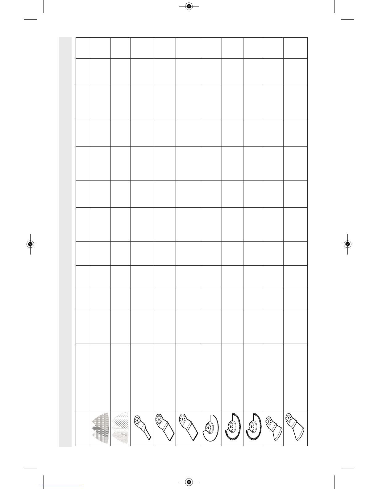
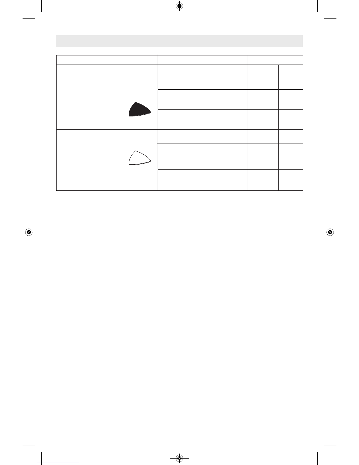
Multi-X Accessory Speed Settings
""'&
,#%##
""'&
,#%"'
##
, ("('
##
, ("('
##'
, ("('
*
%#('!#)
,
%#('!#)
,
%$%
+ %$%
"
!
"
DM 2610033449 02-14_MX30E 2/11/14 12:54 PM Page 12
-13-
APPLICATIONS
Your Bosch Multi-X oscillating tool is intended
f
or sanding and cutting wooden materials,
plastic, plaster and non-ferrous metals. It is
especially suitable for working close to edges,
in tight spaces, and for flush cutting.
Below are some typical uses for your Bosch
Multi-X oscillating tool.
For all accessories, work
with the accessory away
from the body. Never position hand near or
directly in front of working area. Always hold
the tool with both hands and wear protective
gloves.
Flush Cutting
Remove excess wood from door jamb, window
sill and/or toekick. Removing excess copper or
PVC pipe.
Removal work
e.g. carpets & backing, old tile adhesives,
caulking on maso nry, woo d and other
surfaces.
Removal of excess materials
e.g. plaster, mortar splatters, concrete on tiles,
sills.
Preparation of surfaces
e.g. for new floors and tiles.
Detail sanding
e.g. for sanding in extremely tight areas
otherwise difficult to reach and require hand
sanding
CUTTING
Saw blades are ideal for making precise cuts
in tight areas, close to edges or flush to a
surface.
Select a medium to high speed for making
initial plunge, start off at medium speed for
increased control. After making your initial cut,
you can increase speed for faster cutting
ability.
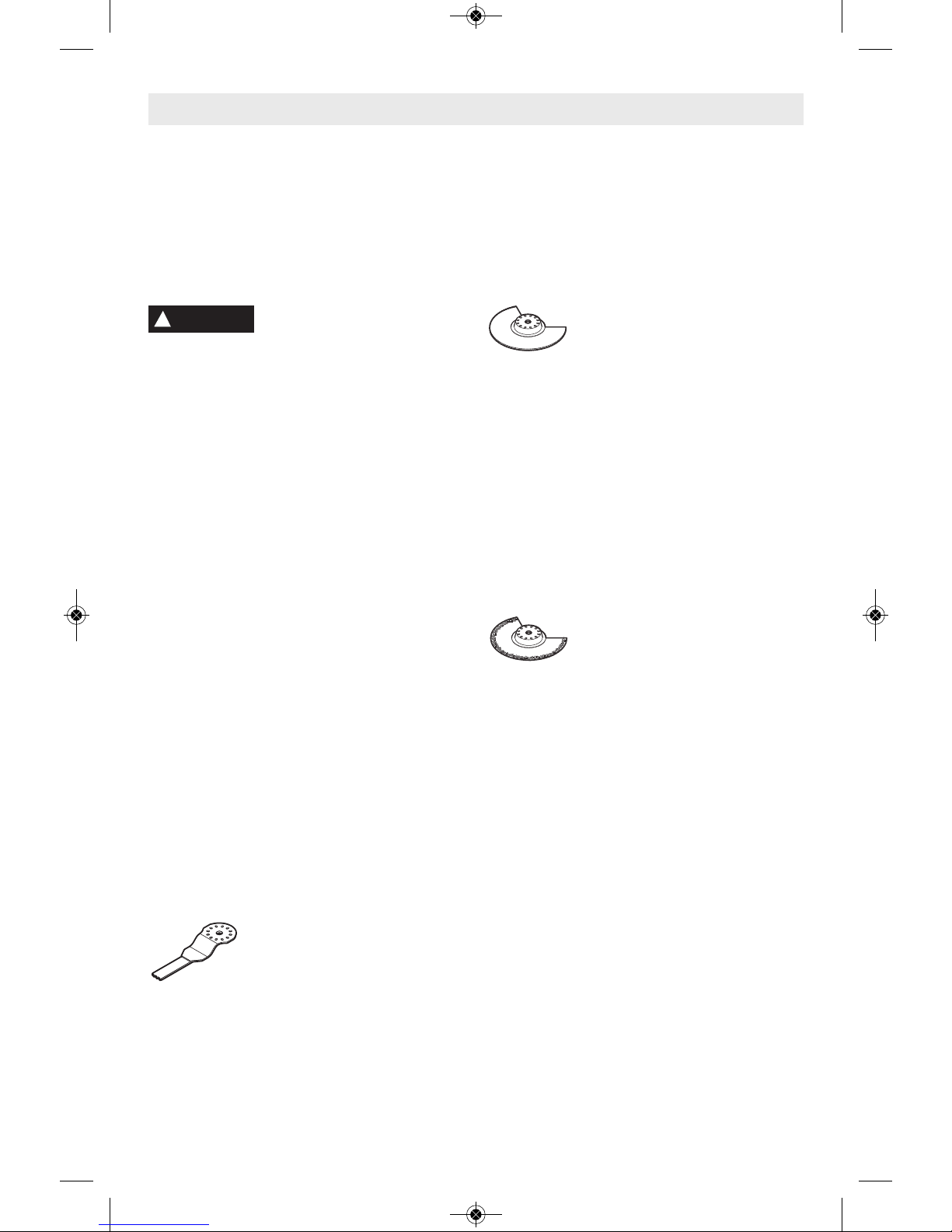
Flush cutting blades are
intended to make precise cuts to
allow for installation of flooring or
wall material. When flush cutting
it is important not to force the tool during the
plunge cut. If you experience a strong vibration
in your ha nd dur ing the plunge cut , this
indicates that you are applying too much
pressure. Back the tool out and let the speed
of the tool do the work. While keeping the teeth
of the blade in the work surface, move the
back of the tool in a slow sideways motion.
This motion will help expedite the cut.
When making a flush cut it is always a good
idea to have a piece of scrap material (tile or
wood) supporting the blade. If you need to rest
the flush cutting blade on a delicate surface,
you should protect the surface with cardboard
or masking tape.
The flat saw blade is ideal for
making pr ecis e c uts in woo d,
plaster, drywall material.
Ap plicati ons inclu de cuttin g open ings in
flooring for venting, repairin g dam aged
flooring, cutting openings for electrical boxes.
The blade works best on softer woods such as
pine. For harder woods, the blade life will be
limited.
Select a medium to high speed.
The fla t saw blad e can also be use d for
window restoration making glazing easy to
remove. The saw blade can be placed directly
against the edge of the window frame, guiding
the blade through the glazing.
GROUT REMOVAL
Grout removal blades are ideal
for removing d amaged or
cracked grout. Gr out blade s
come in different widths (1/16" and 1/8") to
tackle diffe rent grout line widths. Before
selecting a grout blade measure the grout line
width to pick the appropriate blade.
Select a medium to high speed.
To remove the grout, use a back and forth
motion, making several passes along the grout
line. The hardness of the grout will dictate how
many passes are needed. Try and keep the
grout blade aligned with the grout line and be
careful not to apply too much side pressure on
the grout blade during the process. To control
plunge depth use the carbide grit line on the
blade as an indicator. Be careful not to plunge
beyond the carbide grit line to avoid damage to
the backer board material.
The grout blades can handle both sanded and
un sand ed grou t. If you notic e the bla de
clogging during the grout removal process, you
can use a brass brush to clean the grit, thus
exposing the grit again.
The grout blade geometry is designed so that
the blade can remove all grout up to the
su rface of a wa ll or corner. Thi s can be
Operating Applications
!
WARNING
DM 2610033449 02-14_MX30E 2/11/14 12:55 PM Page 13
-14-
accomplished by ensuring that the segmented
portion of the blade is facing the wall or corner.
SCRAPING
Scrapers are suitable for removing old coats of
varnish or adhes ives, removing bond ed
carpeting, e.g. on stairs/steps and other
small/medium size surfaces.
Select low to medium speed.
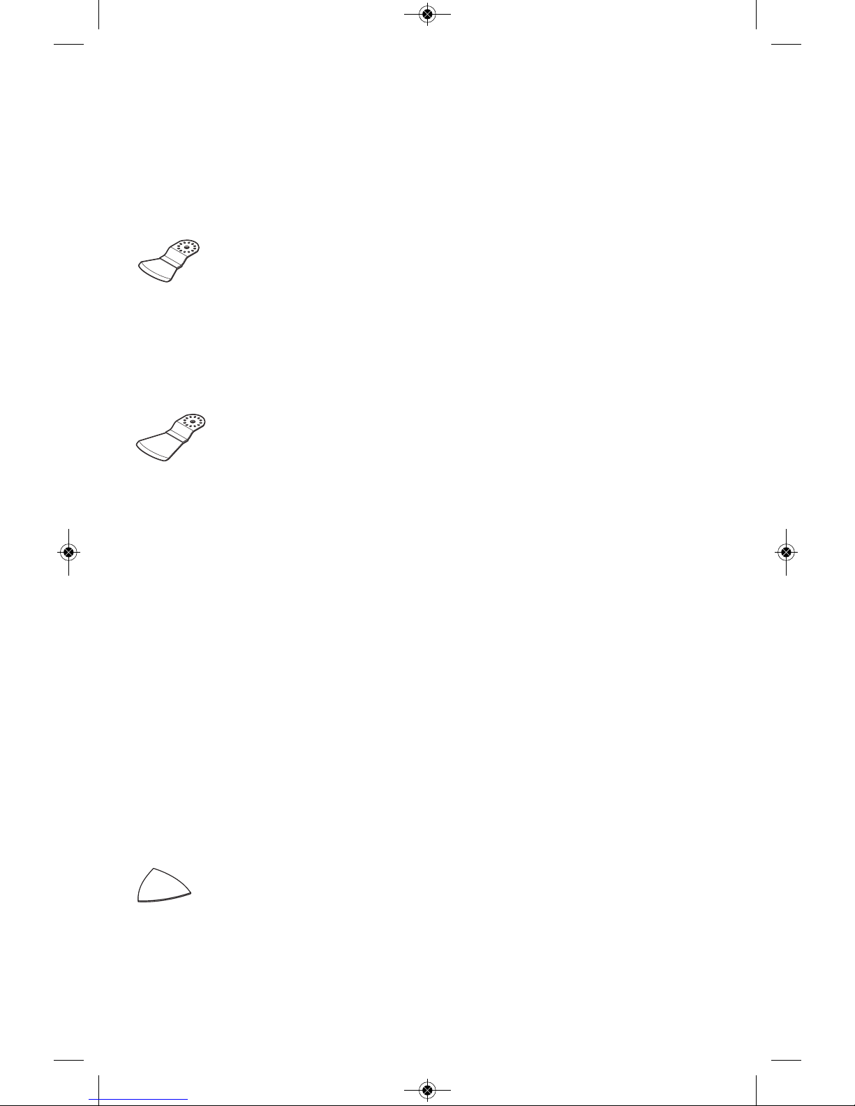
Rigid scrapers are for large area
removal, and harder materials
such as vinyl flooring, carpeting
and t ile adhesive s. When
removing strong, tacky adhesives, grease the
scraper blade surface with (petroleum jelly
or silicone grease) to reduce gumming up.
The carpet/vinyl flooring removes easier if
it is scored prior to removal so the scraper
blade can move underneath the flooring
material.
Flexible scrapers are used for
hard to reach areas and softer
material such as caulk.
Mount the scraper blade with the logo side
facing up. With the flexible scraper, make sure
that the screw head does not make contact
with surface during the scraping process (a 30
- 45 degree pitch is recommend). This can be
accomplished by making sure that the tool is at
an angle to the blade. You should be able to
see the blade flex during the scraping process.
If you are removing caulk from a delicate
surface such as a bath tub or tile back splash,
we recomme nd taping o r protecting th e
surface that the blade will rest on. Use rubbing
alcohol to clean the surface after the caulk
and/or adhesive is removed.
Turn the tool on and place desired accessory
on the area where material is to be removed.
Begin with light pressure. The oscillating
motion of accessor y only occu rs when
pressure is applied to the material to be
removed.
Excessive pressure can gouge or damage the
background surfaces (e.g,. wood, plaster).
SANDING
Sanding accessories are suitable
for dry sanding of wood, metal,
surfaces, corners and edges and
hard to reach areas.
Work with the complete surface of the sanding
pad, not only with the tip.
Corners may be finished using the tip or edge
of the selected accessory, which should
occasionally be rotated during use to distribute
the wear on the accessory and backing pad
surface.
Sand with a continuous motion and light
pressure. DO NOT apply excessive pressure let the tool do the work. Excessive pressure
will result in poor handling, vibration, and
unwanted sanding marks and premature wear
on the sanding sheet.
Always be certain that smaller workpieces are
securely fastened to a bench or other support.
Larger panels may be held in place by hand on
a bench or sawhorses.
Open-coat aluminum oxide sanding sheets are
recommended for most wood or metal sanding
applications, as this synthetic material cuts
quickly and wears well. Some applications,
such as metal finishing or cleaning, require
special abrasive pads which are available from
your dealer. For best results, use Bosch
sanding accessories which are of superior
quality and are carefully selected to produce
professional quality results with your oscillating
tool.
The following suggestions may be used as a
general guide for abrasive selection, but the
best results will be obtained by sanding a test
sample of the workpiece first.
Grit Application
Coarse For rough wood or metal
sanding, and rust or old
finish removal.
Medium For general wood or metal
sanding
Fine For final finishing of wood,
metal, plaster and other
surfaces.
With the workpiece firmly secured, turn tool on
as described above. Contact the work with the
tool after the tool has reached its full speed,
and remove it from the work before switching
the tool off. Operating your oscillating tool in
this manner will prolong switch and motor life,
and greatly increase the quality of your work.
Move the oscillating tool in long steady strokes
parallel to the grain using some lateral motion
to overlap the strokes by as much as 75%.
DO NOT apply excessive pressure - let the
tool do the work. Excessive pressure will result
in poor handling, vibration, and unwanted
sanding marks.
DM 2610033449 02-14_MX30E 2/11/14 12:55 PM Page 14
-15-
Material Application Grit Size
All wooden materials (e.g.,
hardwood, softwood, chipboard,
building board) Metal materials–
Metal materials, fiberglass
and plastics
Paint, varnish, filling compound
and filler
Selecting Sanding/Grinding Sheets
For coarse-sanding, e.g. of
rough, unplanned beams and
boards
For face sanding and planing
small irregularities
For finish and fine sanding of
wood
For sanding off paint
For sanding primer (e.g., for
removing brush dashes, drops
of paint and paint run)
For final sanding of primers
before coating
Coarse
Medium
Fine
Coarse
Medium
Fine
40/60
80/120
180/240
40/60
80/120
180/240
Sand Paper (Red)
Sand Paper (White)
DM 2610033449 02-14_MX30E 2/11/14 12:55 PM Page 15
-16-
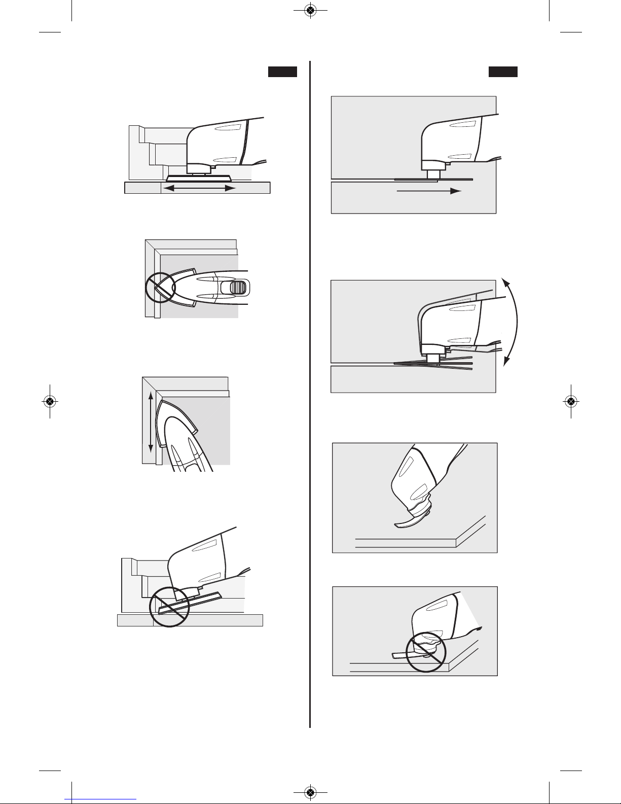
FIG. 6FIG. 5
CORRECT: Sand with a smooth
back and forth motion, allowing the
weight of the tool to do the work.
INCORRECT: Avoid sanding with
only the tip of the pad. Keep as
much sand paper in touch with the
work surface as possible.
CORRECT: Always sand with the
pad and sandpaer flat against the
work surface. Work smoothly in a
back and forth motion.
INCORRECT: Avoid tipping the
pad. Always sand flat.
CORRECT: Always cut with a
smooth back and forth motion.
Never force the blade. Apply light
pressure to guide the tool.
INCORRECT: Do not twist the tool
while cutting.This can cause the
blade to bind.
CORRECT: Make sure flexible
scraper blade flexes enough
INCORRECT: Avoid screw head
touching surface with flexible
scraper blade.
DM 2610033449 02-14_MX30E 2/11/14 12:55 PM Page 16
-17-
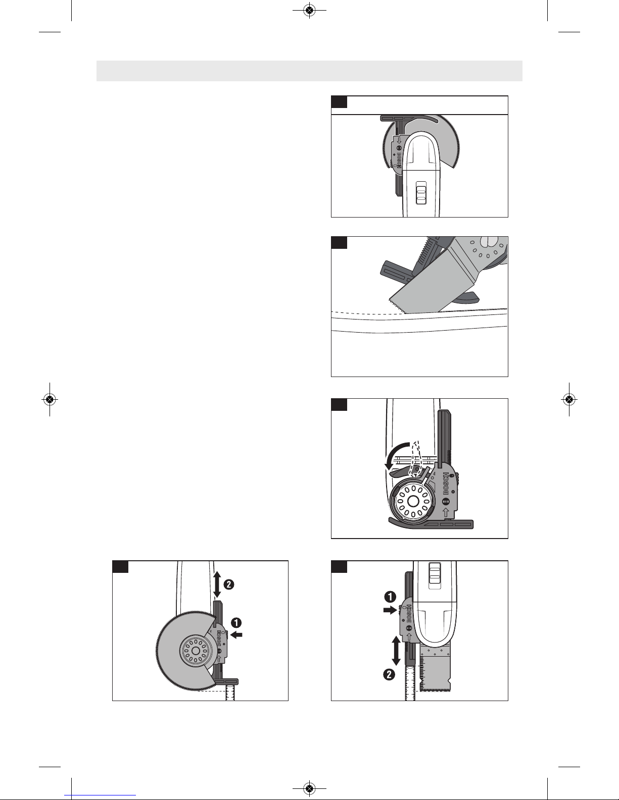
Accessories & Attachments
OSC004 Depth Stop Kit
(
Optional Accessory)
INTRODUCTION
The OSC004 Depth Stop Kit attachment is
comp a t ible w i th th e Bos c h MX3 0 E and
Bosch MXH180 Multi-X Oscillating Tools and
allows the depth of a cut to be limited to a
user-selected depth. (FIG.A) It can also be
used to provide guidance for other types of
cuts. (FIG. B)
INSTALLATION
Step 1: If an accessory has already been
installed on the tool, remove it.
Step 2: Place the bracket onto the nose of
the Multi-X tool such that the clamp
is facing the rear of the tool. (FIG. C)
Step 3: Press the clamp shut. (FIG. C)
Step 4: Push the appropriate guide into the
opening in the front of the bracket.
Step 5: Install the accessory onto the tool.
Step 6: Set the desired cutting depth using
the red button on the side of the
bracket. (FIG. C & D)
PLUNGE CUTS
• For plunge cutting using round blades,
such as “segment” blades, install the wide
stop as shown in figure D.
• F o r plunge-cu t blades u s ing st r a i g h t
blades, install the narrow stop as shown in
figure E.
OTHER TYPES OF GUIDED CUTS
• For other types of guided cuts, install the
wide stop as shown in figure B.
A
B
C
D
E
DM 2610033449 02-14_MX30E 2/11/14 12:55 PM Page 17
 Loading...