

Bosch MS 6 User Manual
Engine Control Unit MS 6
Manual
Version 1.0 06/05/2019

Content
ii/76 Engine_Control_Unit_MS_6.x_Manual Bosch Motorsport
Content
1 Getting Started................................................................................................................................................................ 3
2 Technical Data................................................................................................................................................................. 4
2.1 System Layout........................................................................................................................................................................................................ 4
2.2 Mechanical Data ................................................................................................................................................................................................... 7
2.3 Electrical Data ........................................................................................................................................................................................................ 9
2.4 Disposal.................................................................................................................................................................................................................... 25
3 Starting up....................................................................................................................................................................... 26
3.1 Installation of Software Tools .......................................................................................................................................................................... 26
3.2 Configuration of the system............................................................................................................................................................................. 27
4 Prepare Data Base........................................................................................................................................................... 33
4.1 Initial Data Application....................................................................................................................................................................................... 33
4.2 Peripherals............................................................................................................................................................................................................... 39
4.3 Throttle Control..................................................................................................................................................................................................... 41
4.4 Vehicle Test............................................................................................................................................................................................................. 44
5 ECU plus Data Logger..................................................................................................................................................... 47
5.1 Software Tools....................................................................................................................................................................................................... 47
5.2 First Recording (Quick Start)............................................................................................................................................................................ 47
5.3 USB Data Recording............................................................................................................................................................................................ 49
6 Project Configuration..................................................................................................................................................... 50
6.1 Math Channels....................................................................................................................................................................................................... 50
6.2 Conditional Function........................................................................................................................................................................................... 51
6.3 Condition Channels ............................................................................................................................................................................................. 53
6.4 CPU Load ................................................................................................................................................................................................................. 53
7 CAN Configuration ......................................................................................................................................................... 54
7.1 CAN Bus Trivia ....................................................................................................................................................................................................... 54
7.2 CAN Input................................................................................................................................................................................................................ 55
7.3 CAN Output............................................................................................................................................................................................................ 64
8 Online Measurement and Calibration .......................................................................................................................... 68
8.1 Setting up an Online Measurement.............................................................................................................................................................. 68
8.2 Using the Measurement Sheets...................................................................................................................................................................... 69
9 Error Memory .................................................................................................................................................................. 70
9.1 Error Memory representing in RaceCon...................................................................................................................................................... 70
9.2 Writing an Error..................................................................................................................................................................................................... 70
9.3 Error Memory Properties................................................................................................................................................................................... 71
Getting Started | 1
Bosch Motorsport Engine_Control_Unit_MS_6.x_Manual 3/76
1 Getting Started
Disclaimer
Due to continuous enhancements we reserve the rights to change illustrations, photos or
technical data within this manual. Please retain this manual for your records.
Before starting
Before starting your engine for the first time, install the complete software. Bosch
Motorsport software is developed for Windows operation systems. Read the manual carefully and follow the application hints step by step. Don’t hesitate to contact us. Contact
data can be found on the backside of this document.
CAUTION
Risk of injury if using the MS 6 inappropriately.
Use the MS 6 only as intended in this manual. Any maintenance or repair must be performed by authorized and qualified personnel approved by Bosch Motorsport.
CAUTION
Risk of injury if using the MS 6 with uncertified combinations and
accessories
Operation of the MS 6 is only certified with the combinations and accessories that are
specified in this manual. The use of variant combinations, accessories and other devices
outside the scope of this manual is only permitted when they have been determined to be
compliant from a performance and safety standpoint by a representative from Bosch
Motorsport.
NOTICE
For professionals only.
The Bosch Motorsport MS 6 was developed for use by professionals and requires in depth
knowledge of automobile technology and experience in motorsport. Using the system
does not come without its risks.
It is the duty of the customer to use the system for motor racing purposes only and not
on public roads. We accept no responsibility for the reliability of the system on public
roads. In the event that the system is used on public roads, we shall not be held responsible or liable for damages.
NOTICE
Drive-by-wire systems
For systems with drive-by-wire additional safety provisions apply. For details please refer
to the document „Safety Instructions for Drive-by-Wire Systems in Motorsport Applications“.
2 | Technical Data
4/76 Engine_Control_Unit_MS_6.x_Manual Bosch Motorsport
2 Technical Data
The MS 6 engine control unit features a powerful digital processing dual-core with floating point arithmetic and a high-end field programmable gate array FPGA for ultimate performance and flexibility.
The software development process is based on MATLAB® & Simulink®. It significantly
speeds algorithm development by using automatic code and documentation generation.
Custom functions can be generated quickly and easily. The flexible hardware design allows
the MS 6 to support complex or unusual engine or chassis configurations. Integrated logger control areas present a cost efficient and weight optimized all-in-one solution.
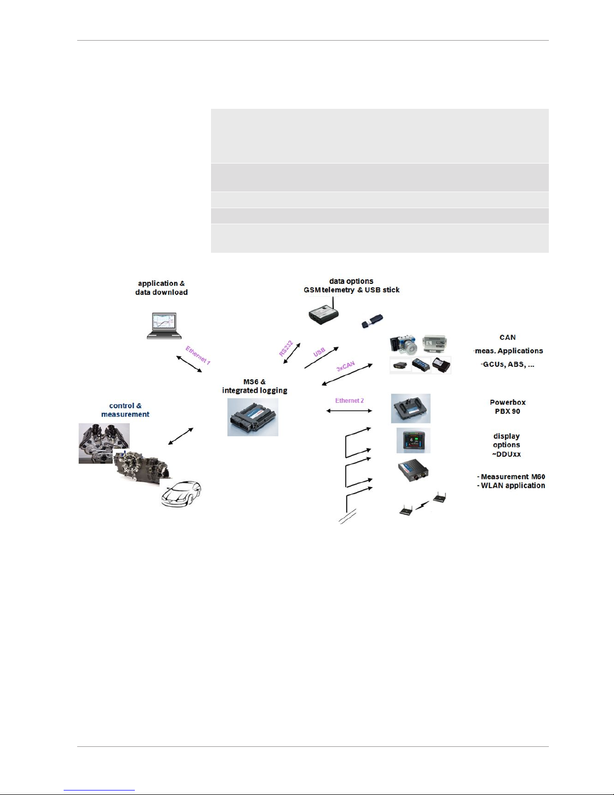
2.1 System Layout
– Controls for max. 12 cylinder engines are available with the selection of low- or high
pressure injection.
– Integrated torque-structures for power control functions as speed-, launch, rpm and
traction limitations or regulations
– Two engine bank related separated lines for physical air mass determination, influ-
enced by own Lambda corrections
– Options from simple gear cut support up to complete gear change functions
– Different target maps to differ applications like Lambda-, spark- and electrical throttle
controls
– State of the art engine functions like fuel cut off, idle control, injection valve correc-
tions and knock control are already integrated in the basic program structure.
– Sequential fuel injection realized also for asymmetric injection and ignition timings
– Various networks like 2 Ethernet-, 1 USB, 1 LIN for system communication, 3 configur-
able CAN for external device communication and 1 RS232 for online telemetry data.
– Functionalities may be linked to in and outputs for free system design or harness ad-
aptation
– Internal data logger divided into 2 partitions, 1 GB each
Technical Data | 2
Bosch Motorsport Engine_Control_Unit_MS_6.x_Manual 5/76
– Option to copy all data to removable USB stick
Layout restrictions
Ethernet Network MS 6, as Time master, permits the extension of two additional
devices. Using MS 6.1 F02UV01961-03, MS 6.2 F02UV01867-06,
MS 6.3 F02UV01963-03 or MS 6.4 F02UV02019-06 permits the
extension of 4 additional devices.
CAN Network Extended number of members and wiring leads extend the risk of
error frames
RS232 Limited to one additional component
USB Limited to additional Bosch Motorsport USB stick
LIN Permitted for the use of Bosch Motorsport preconfigured config-
urations
2.1.1 Structure MS 6 Devices, Licenses and Order
Numbers
To accommodate the wide range of different engine requirements and race track operating conditions, the MS 6 Motronic system is classified into the main groups high- and low
pressure injection support, subdivided into fully equipped- and functional reduced versions.
Beside the change from low- to high pressure systems, all limited functions may be activated later. The license concept is related to the individual device and the requested upgrading.

2 | Technical Data
6/76 Engine_Control_Unit_MS_6.x_Manual Bosch Motorsport
For MS 6.1
Engine function package I To activate electronic throttle,
camshaft and turbo control
F 02U V02 001-01
Engine function package II To activate traction and
launch control
F 02U V02 002-01
For MS 6.1 and MS 6.3
Measurement package To increase from 21 to 42
analog channel inputs
F 02U V02 000-01
For MS 6.3
High pressure injection package
To activate 2nd engine bank
and 2nd MSV controls
F 02U V01 999-01
For all MS 6 Versions
Logger package I Increase the number of
measure channels up to 720
Sampling up to 1,000 Hz or 1
synchro
Max. number of 1,080 channels are to respect
F 02U V01 993-01
Logger package II Activation of partition 2, 1 GB
memory, 720 channels
Sampling up to 1,000 Hz or 1
synchro
Long term recording, own
data protection code
F 02U V01 998-01
Logger package III Copy data to USB data stick,
USB-port unlocked
– Incl. adapter cable to
USB-port
– Incl. rugged USB flash
drive
– Incl. connector for wiring
harness
F 02U V02 082-01
Gear control package I Gear change control, based
upon Megaline functions
(License model via Megaline)
F 02U V02 107-01
On request
Gear control package II Strategy for pneumatic
forced gear change control
F 02U V02 108-01
Gear control package III Support for external GCU like
Cosworth or Megaline
(included for base versions
beginning with
MS6A_BASE_0800 or comparable)
F 02U V02 109-01
On request
Customer Code Area Enable Customer Code Area F 02U V02 511-01

Technical Data | 2
Bosch Motorsport Engine_Control_Unit_MS_6.x_Manual 7/76
NOTICE
Verify the necessity of gearbox control licenses by checking the Features info window in RaceCon (see section Feature/License Activation
[}31]).
2.2 Mechanical Data
Aluminum housing
2 automotive connectors, 196 pins in total
Vibration suppression via multipoint fixed circuit boards
Size without connectors 226 x 181 x 44 mm
Weight 1,086 g
Protection Classification IP54
Temperature range -20 to 80°C
Inspection services recommended after 220 h or 2 years, no components to replace
2 | Technical Data
8/76 Engine_Control_Unit_MS_6.x_Manual Bosch Motorsport

Technical Data | 2
Bosch Motorsport Engine_Control_Unit_MS_6.x_Manual 9/76
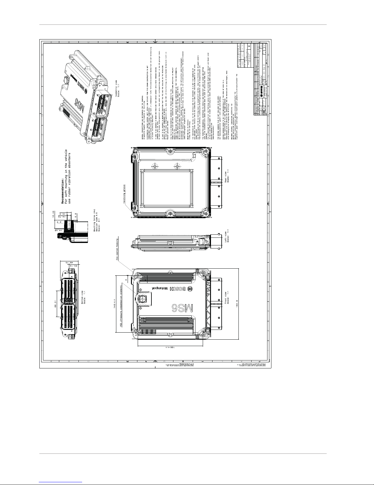
2.2.1 Installation
Mounting 4 housing integrated screw sockets
Offer drawing Available at Bosch Motorsport website on MS 6 product page.
3D Data Available at Bosch Motorsport website on MS 6 product page.
Recommendation
Use rubber vibration absorbers for soft mounting in the vehicle. To assist the heat flow,
especially if HP injection is active, the device has to be mounted uncovered and air circulation has to be guaranteed around the entire surface area.
Inside touring cars placement passenger side is favored, open connectors should not be
uncovered to vertical axe. It has to be assured in mounting position that water cannot infiltrate through wiring harness into the ECU and that the pressure compensating element
and the sealing in the revolving groove do not get submerged in water. Wiring harness
needs to be fixed mechanically in the area of the ECU in a way that excitation of ECU have
the same sequence.
2.3 Electrical Data
Power supply 6 to 18 V
CPU Dual Core 667 MHz; FPGA
2.3.1 Communication
3 x CAN The MS 6 has 3 CAN buses configurable as input and output. Dif-
ferent baud rates are selectable. Please note that the MS 6 contain
integrated switchable 120 Ohm CAN termination resistors.
1 x LIN The Bus is not configurable by the customer, but Bosch Motorsport
offers data selectable protocols to integrate LIN based devices into
the system.
2 x Ethernet Integrated are 100 Mbit full duplex Ethernet communication ports,
internally connected with an Ethernet switch. The ports have “cable
auto crossover” functionality
1 x USB For data transfer to an USB-stick
1 x RS232 One serial port with programmable baud rate for online telemetry
1 x Timesync Coordination
For additional devices added via Ethernet

2 | Technical Data
10/76 Engine_Control_Unit_MS_6.x_Manual Bosch Motorsport
2.3.2 Inputs
The analogue inputs are divided in different hardware classes and qualities.
3.01 kOhm pull-ups are fixed or switchable designed to assist passive sensor elements like
NTC temperature sensors or to change to active signal inputs.
Some of the inputs assist only active sensors and offer no pull-up.
To improve measurement tasks, angle related measurements are an option for some inputs, mainly used for engine related leading signals.
The connection between function and related input is free selectable, beside electronic
throttle functionalities.
All linearization mappings are open to the customer, some signals offer online modes to
calibrate gain and offset.
Digital inputs for speed measuring offer divers hardware options to connect inductive- or
digital speed sensors.
Please respect: for camshaft- or wheel speed signals Hall-effect or DF11 sensors have to
be used and for wide range Lambda measurement and control the Lambda sensor Bosch
LSU 4.9 has to be used.
42 analog inputs in a mix of different hardware designs
6 x reserved for electronic throttle controls
10 x no integrated pull-up
4 x option for time synchronous measurement, no integrated pull-up
2 x option for time synchronous measurement, switchable 1.47 kOhm pull-up
5 x fixed 3.01 kOhm pull-up
13 x switchable 3.01 kOhm pull-up
2 x thermocouple exhaust gas temperature sensors (K-type)
6 internal measurements
1 x ambient pressure
1 x triax acceleration
2 x ECU temperature
2 x ECU voltage
8 function related inputs
2 x Lambda interfaces for LSU 4.9 sensor types
1 x lap trigger/beacon input
4 x knock sensors
1 x digital switch for engine ON/OFF
9 digital inputs for speed and position measurements
1 x switchable Hall or inductive sensor for flywheel measurement
2 x Hall sensor for sync wheel detection
4 x switchable Hall or DF11 sensors for camshaft position or wheel speed
2 x switchable Hall or inductive sensors for turbo speed measurement

Technical Data | 2
Bosch Motorsport Engine_Control_Unit_MS_6.x_Manual 11/76
2.3.3 Sensor supplies and screens
4 x sensor supplies 5 V / 50 mA
3 x sensor supplies 5 V / 150 mA
7 x sensor grounds
2 x sensor screens
2.3.4 Outputs
19 freely configurable outputs in a mix of different hardware designs
8 x 2.2 amp pwm lowside switch
4 x 3 amp pwm lowside switch
2 x 4 amp pwm lowside switch
2 x 1 amp pwm lowside switch
2 x 1 amp pwm lowside switch, low dump resistant
1 x 8.5 amp H-bridge
38 function related outputs
12 x ignition controls, support of coils with integrated amplifier only
12 x low pressure injection power stages for high impedance valves
(max. 2.2 amps and min. 6 Ohm internal resistance of the injectors)
8 x high pressure injection power stages for magnetic valves (HDEV 5)
2 x outputs for high pressure pump controls (MSV)
2 x 8.5 amp H-bridge for electronic throttle control
2 x 4 amp pwm lowside switch for Lambda heater
3 output signals
1 x flywheel
1 x trigger wheel
1 x engine rpm

2 | Technical Data
12/76 Engine_Control_Unit_MS_6.x_Manual Bosch Motorsport
2.3.5 Supply System
Please ensure that you have a good ground installation with a solid, low resistance connection to the battery minus terminal. The connection should be free from dirt, grease,
paint, anodizing, etc.
– MS 6 power consumption at appr. 13 V (vary according to use cases)
– ~ 25 - 30 amps (4 cyl. FDI at 8,500 1/min/200 bar single injection, 1 MSV, 1 elec-
tronic throttle, standard chassis equipment)
– ~ 35 - 40 amps (8 cyl. FDI at 8,500 1/min/200 bar single injection, 2 MSV, 2 elec-
tronic throttle, standard chassis equipment)
– Power consumption of LP-injectors, actuators and coils are to calculate separately.
– The MS 6 power supply is separated into the maintenance of controller and power
stages.
– Ensure controller supply is activated before the power stages.
– The MS 6 is able to control a main relay or even the power box itself via a low side
output.
– As long as the controller is activated, data logging, telemetry and communication is
also ongoing.
– The engine On/Off switch activates the ignition and injection outputs to enable en-
gine start separately from power supply.

Technical Data | 2
Bosch Motorsport Engine_Control_Unit_MS_6.x_Manual 13/76
2.3.6 Pin Layout
The pin layout is also available at Bosch Motorsport website on MS 6 product page.
Most of MS 6 functions to pin relations may be modified to projects demands.
Please see details in the function description SWITCHMATRIX.
Bosch Motorsport tests check the defined connections of the pin layout.
Using a MS 6.1 or MS 6.3 version ensure not using analogue inputs of the measurement package without enabled license.
For MS 6.1 and MS 6.3 these hardware-options are only available if MS 6 measurement package is in use.
Analogue Inputs
ECU Pin
connector
>A<
ECU Pin
connector >K<
MS6.1 MS6.3
measure package
MS6.Cup
not available
I/O Type description pin related functions LEAD
AWG
MS6 default functionality function to pin coordination Measure
channel
A032 analog input pullup 3k01, 12bit 24 engine temperature PIN_IN_UTMOT utmot
A033 analog input pullup 3k01, 12bit 24 oil temperature PIN_IN_UTOIL utoil
A034 analog input pullup 3k01, 12bit 24 intake air temperature PIN_IN_UTINT utint
A035 Measure pack-
age
not available analog input pullup 3k01, 12bit 24 fuel temperature PIN_IN_UTFUEL utfuel
A079 analog input no pullup, 12bit angle- or time related
measurement
24 rail pressure PIN_IN_UPRAIL uprail
A080 Measure pack-
age
not available analog input no pullup, 12bit angle- or time related
measurement
24 rail pressure, bank 2 PIN_IN_UPRAIL2 uprail2
A081 analog input no pullup, 12bit 24 fuel pressure PIN_IN_UPFUEL upfuel
A082 analog input switch.-pullup 3k01 12bit CWPULLUP_A082 24 oil pressure PIN_IN_UPOIL upoil
A058 analog input no pullup, 12bit angle- or time related
measurement
24 pressure upstream throttle PIN_IN_UP21 up21
A059 Measure pack-
age
not available analog input switch.-pullup 1k47 for future dvlp., 12bit
angle- or time related measurement
24 pressure upstream throttle,
bank 2
PIN_IN_UP21_2 up21_2
A060 analog input no pullup, 12bit angle- or time related
measurement
24 intake manifold pressure, mean
value
PIN_IN_UP22M up22m
A061 Measure pack-
age
not available analog input switch.-pullup 1k47 for future dvlp., 12bit
angle- or time related measurement
24 intake manifold pressure, mean
value, bank 2
PIN_IN_UP22M_2 up22m_2
A056 analog input no pullup, 12bit 24 APS potentiometer a fixed function to pin coordina-
tion
uaps_a
A054 analog input no pullup, 12bit 24 APS potentiometer b fixed function to pin coordina-
tion
uaps_b
A041 analog input no pullup, 12bit 24 throttle potentiometer fixed function to pin coordina-
tion
uthrottle
A053 analog input no pullup, 12bit 24 backup throttle potentiometer fixed function to pin coordina-
tion
uthrottle_b
A036 not available analog input no pullup, 12bit 24 throttle potentiometer, bank 2 fixed function to pin coordina-
tion
uthrottle2
A037 not available analog input no pullup, 12bit 24 backup throttle potentiometer,
bank 2
fixed function to pin coordination
uthrottle2_b

2 | Technical Data
14/76 Engine_Control_Unit_MS_6.x_Manual Bosch Motorsport
K036 analog input pullup 3k01, 12bit 24 map switch PIN_IN_UMAPSW umapsw
K031 analog input switch.-pullup 3k01 12bit CWPULLUP_K031 24 pitspeed switch PIN_IN_UPITSPEEDSW upitspeedsw
K019 Measure pack-
age
analog input switch.-pullup 3k01 12bit CWPULLUP_K019 24 launch control switch PIN_IN_ULAUNCHSW ulaunchsw
K015 analog input switch.-pullup 3k01 12bit CWPULLUP_K015 24 traction control switch PIN_IN_UTCSW utcsw
K016 Measure pack-
age
not available analog input switch.-pullup 3k01 12bit CWPULLUP_K016 24 reset chassis channels switch PIN_IN_UCHRESSW uchressw
K017 Measure pack-
age
not available analog input switch.-pullup 3k01 12bit CWPULLUP_K017 24 wet track switch PIN_IN_UWETSW uwetsw
A039 analog input no pullup, 12bit 24 gear position PIN_IN_UGEARP ugearp
A055 Measure pack-
age
analog input switch.-pullup 3k01 12bit CWPULLUP_A055 24 reverse shift switch PIN_IN_UREVSW ushiftrevsw
A057 Measure pack-
age
analog input switch.-pullup 3k01 12bit CWPULLUP_A057 24 downshift switch PIN_IN_USHIFTDNSW ushiftdnsw
A076 Measure pack-
age
analog input switch.-pullup 3k01 12bit CWPULLUP_A076 24 upshift switch PIN_IN_USHIFTUPSW ushiftupsw
A077 analog input switch.-pullup 3k01 12bit CWPULLUP_A077 24 gearshift PIN_IN_UGS ugs
A078 Measure pack-
age
analog input switch.-pullup 3k01 12bit CWPULLUP_A078 24 free measure channel A78
A038 Measure pack-
age
analog input no pullup, 12bit 24 gearbox pneumatic pressure PIN_IN_UPGEARAIR upgearair
K033 Measure pack-
age
analog input no pullup, 12bit 24 clutch pressure PIN_IN_UPCLUTCH upclutch
K048 Measure pack-
age
not available analog input no pullup, 12bit 24 free measure channel K48
K047 digital input fixed pullup to 5volts 24 laptrigger fixed function to pin coordina-
tion
lapctr
A040 analog input no pullup, 12bit 24 brake pressure rear PIN_IN_UPBRAKE_R upbrake_r
K020 analog input switch.-pullup 3k01 12bit CWPULLUP_K020 24 brake pressure front PIN_IN_UPBRAKE_F upbrake_f
K018 Measure pack-
age
not available analog input switch.-pullup 3k01 12bit CWPULLUP_K018 24 damper sensor front/left PIN_IN_UDAM_FL udam_fl
K032 Measure pack-
age
not available analog input no pullup, 12bit 24 damper sensor front right PIN_IN_UDAM_FR udam_fr
K034 Measure pack-
age
not available analog input no pullup, 12bit 24 damper sensor rear left PIN_IN_UDAM_RL udam_rl
K035 Measure pack-
age
not available analog input no pullup, 12bit 24 damper sensor rear right PIN_IN_UDAM_RR udam_rr
K050 Measure pack-
age
not available analog input no pullup, 12bit 24 steering angle PIN_IN_USTEER usteer
K077 Thermo-
couple input
k-type sensor 24shield
thermo
exhaust gas temperature fixed function to pin coordina-
tion
utexh
K076
K079 Measure pack-
age
not available Thermo-
couple input
k-type sensor 24shield
thermo
exhaust gas temperature bank 2 fixed function to pin coordina-
tion
utexh2
K078 Measure pack-
age
not available

Technical Data | 2
Bosch Motorsport Engine_Control_Unit_MS_6.x_Manual 15/76
Digital Inputs
ECU Pin connector >A<
ECU Pin connector >K<
MS6.1 MS6.3
measure package
MS6.Cup
not available
I/O Type description pin related functions LEAD
AWG
MS6 default functionality function to pin coordination Measure
channel
A047 crankshaft+
(Hall/Inductive)
switchable between halleffect- and inductive sensor
CWINTF_CRANK
PIN_IN_CRANK
CWINTF_CRANK_K
CWINTF_CRANK_TH
24shield engine speed fixed function to pin coordin-
ation
nmot
A048 crankshaft -
(inductive)
24shield
A074 digital input halleffect sensor only 24shield camshaft inlet PIN_IN_CAM_IN cam_pos_edg
es_001
A075 digital input halleffect sensor only 24shield camshaft outlet PIN_IN_CAM_OUT cam_pos_edg
es_out_001
A049 digital input switchable between halleffect- or DF11
sensors
CWINTF_A049 24shield camshaft inlet bank2 or
wheelspeed front right
PIN_IN_CAM_IN2 or
PIN_IN_FWEEL_FR
cam_pos_edg
es2_001 or
fwheel_fr
A050 digital input switchable between halleffect- or DF11
sensors
CWINTF_A050 24shield camshaft outlet bank2 or
wheelspeed front left
PIN_IN_CAM_OUT2 or
PIN_IN_FWEEL_FL
cam_pos_edg
es_out2_001
or fwheel_fl
A051 digital input switchable between halleffect- or DF11
sensors
CWINTF_A051 24shield wheelspeed rear right PIN_IN_FWHEEL_RR fwheel_rr
A052 digital input switchable between halleffect- or DF11
sensors
CWINTF_A052 24shield wheel speed rear left PIN_IN_FWHEEL_RL fwheel_rl
K045 digital input switchable between halleffect- and in-
ductive sensor
CWINTF_K045
CWINTF_K045_K
CWINTF_K045_TH
24shield turbo speed PIN_IN_FTURBO fturbo
K046 digital input switchable between halleffect- and in-
ductive sensor
CWINTF_K046
CWINTF_K046_K
CWINTF_K046_TH
24shield turbo speed bank2 PIN_IN_FTURBO2 fturbo2
K062 ground sup-
ply
if inductive sensos are connected to K045
or K046
24shield ground for turbo speed and--2
K054 digital input B_engon 20 Engine On/Off switch b_engon(_in)
A013 knock input 24shield knock sensor 1, bank1 KCSENCYL ikcraw_n_..
A014 knock input 24shield knock sensor 2, bank1 KCSENCYL ikcraw_n_..
A015 not avl. knock input 24shield knock sensor 1, bank2 KCSENCYL ikcraw_n_..
A016 not avl. knock input 24shield knock sensor 2, bank2 KCSENCYL ikcraw_n_..
A017 knock sensor
ground
24shield
K085 Lambda_IA LSU4.9 probe only 24 Lambda fixed function to pin
coordination
lambda
K086 Lambda_IP 24
K087 Lambda_UN 24
K088 Lambda_VM 24
K068 not avl. Lambda_IA LSU4.9 probe only 24 Lambda bank2 fixed function to pin
coordination
lambda2
K069 not avl. Lambda_IP 24

2 | Technical Data
16/76 Engine_Control_Unit_MS_6.x_Manual Bosch Motorsport
K070 not avl. Lambda_UN 24
K071 not avl. Lambda_VM 24
Ignition- & Injection Outputs
ECU Pin
connector >A<
ECU Pin
connector >K<
MS6.1 MS6.3
measure package
MS6.Cup
not available
I/O Type description pin related
functions
LEAD
AWG
MS6 default functionality function to pin coordination Measure
channel
A026 ignition driver output related to mechanical cylinder
number;
use of coil integrated power stages only
CWIGNDRV_MODE
IGNDRV_CURRENT
24 Ignition cyl.1 CYLNUMBER
CYLANGLE
ign_out_n_00
1
A027 24 Ignition cyl.2 ign_out_n_00
2
A028 24 Ignition cyl.3 ign_out_n_00
3
A029 24 Ignition cyl.4 ign_out_n_00
4
A030 not avl. 24 Ignition cyl.5 ign_out_n_00
5
A031 not avl. 24 Ignition cyl.6 ign_out_n_00
6
A068 not avl. 24 Ignition cyl.7 ign_out_n_00
7
A069 not avl. 24 Ignition cyl.8 ign_out_n_00
8
A070 not avl. 24 ignition cyl.9 ign_out_n_00
9
A071 not avl. 24 ignition cyl.10 ign_out_n_01
0
A072 not avl. 24 ignition cyl.11 ign_out_n_01
1
A073 not avl. 24 ignition cyl.12 ign_out_n_01
2
A098 low pressure
output for
high imp.
injectors
output related to mechanical cylinder
number
24twist Injection cyl.1 CYLNUMBER
CYLANGLE
or
(PIN_OUT_LPINJ_A098
…
PIN_OUT_LPINJ_A084)
tinj_n_001
A100 24twist Injection cyl.2 tinj_n_002
A101 24twist Injection cyl.3 tinj_n_003
A096 24twist Injection cyl.4 tinj_n_004
A099 not avl. 24twist Injection cyl.5 tinj_n_005
A103 not avl. 24twist Injection cyl.6 tinj_n_006
A042 not avl. 24twist Injection cyl.7 tinj_n_007
A105 not avl. 24twist Injection cyl.8 tinj_n_008
A018 not avl. 24twist Injection cyl.9 tinj_n_009
A020 not avl. 24twist Injection cyl.10 tinj_n_010
A063 not avl. 24twist Injection cyl.11 tinj_n_011
A084 not avl. 24twist Injection cyl.12 tinj_n_012

Technical Data | 2
Bosch Motorsport Engine_Control_Unit_MS_6.x_Manual 17/76
A043 high pressure
outputs for
magnetic
injectors
INJVH1 20twist Injection cyl.A PIN_OUT_HPIN-
J11A_A043_A064
tinj_n_(cyl.A)
A064 INJVL11 20twist
A002 not avl. INJVH3 20twist Injection cyl.B PIN_OUT_HPIN-
J12E_A002_A023
tinj_n_(cyl.B)
A023 not avl. INJVL32 20twist
A003 INJVH2 20twist Injection cyl.C PIN_OUT_HPIN-
J21C_A003_A024
tinj_n_(cyl.C)
A024 INJVL21 20twist
A046 not avl. INJVH4 20twist Injection cyl.D PIN_OUT_HPIN-
J22G_A046_A067
tinj_n_(cyl.D)
A067 not avl. INJVL42 20twist
A044 not avl. INJVH1 20twist Injection cyl.E PIN_OUT_HPIN-
J31F_A044_A065
tinj_n_(cyl.E)
A065 not avl. INJVL12 20twist
A001 INJVH3 20twist Injection cyl.F PIN_OUT_HPIN-
J32B_A001_A022
tinj_n_(cyl.F)
A022 INJVL31 20twist
A004 not avl. INJVH2 20twist Injection cyl.G PIN_OUT_HPIN-
J41H_A004_A025
tinj_n_(cyl.G)
A025 not avl. INJVL22 20twist
A045 INJVH4 20twist Injection cyl.H PIN_OUT_HPIN-
J42D_A045_A066
tinj_n_(cyl.H)
A066 INJVL41 20twist
Outputs
ECU Pin
connector >A<
ECU Pin connector >K<
MS6.1 MS6.3
measure package
MS6.Cup
not available
I/O Type description pin related functions LEAD
AWG
MS6 default functionality function to pin coordination Measure
channel
A095 lowside switch 4 amps pwm 24twist camshaft inlet control fixed pin to output control co-
ordination
cam_pwm
A021 not avl. lowside switch 4 amps pwm 24twist camshaft inlet control bank2 fixed pin to output control co-
ordination
cam_pwm2
A102 lowside switch 3 amps pwm 24twist camshaft outlet control fixed pin to output control co-
ordination
cam_pwm_o
ut
A094 not avl. lowside switch 3 amps pwm 24twist camshaft outlet control bank2 fixed pin to output control co-
ordination
cam_pwm_o
ut2
A019 lowside switch 3 amps pwm 24twist PIN_OUT_A019
A104 not avl. lowside switch 3 amps pwm 24twist PIN_OUT_A104
A097 lowside switch 2,2 amps pwm 24twist wastegate increase PIN_OUT_A097 wgc_inc_pw
m
A093 not avl. lowside switch 2,2 amps pwm 24twist wastegate increase bank2 PIN_OUT_A093 wgc_inc_pw
m2
K039 not avl. lowside switch 2,2 amps pwm 24twist PIN_OUT_K039
K056 lowside switch 2,2 amps pwm 24twist air conditioning compressor PIN_OUT_K056 comp_pwm
K038 lowside switch 2,2 amps pwm 24twist gearshift actuator upshift PIN_OUT_K038 shiftup_pwm
K040 not avl. lowside switch 2,2 amps pwm 24twist PIN_OUT_K040
K055 lowside switch 2,2 amps pwm 24twist gearshift actuator downshift PIN_OUT_K055 shiftdn_pwm
K074 lowside switch 2,2 amps pwm 24twist PIN_OUT_K074
K089 lowside switch 1 amps pwm 24twist fuel pump relay PIN_OUT_K089 fpump_pwm
K073 not avl. lowside switch 1 amps pwm 24twist PIN_OUT_K073

2 | Technical Data
18/76 Engine_Control_Unit_MS_6.x_Manual Bosch Motorsport
K057 lowside switch 1amp pwm reset < 3,5V 24twist control main relay fixed pin to output control co-
ordination
b_mainrelay
K072 lowside switch 1amp pwm reset < 3,5V 24twist Kl.50 / starter control fixed pin to output control co-
ordination
b_starter
K022 lowside switch 4 amp pwm 24twist heater lambda fixed pin to output control co-
ordination
lsuh_out
K023 not avl. lowside switch 4 amp pwm 24twist heater lambda2 fixed pin to output control co-
ordination
lsuh_out2
H-Bridges & Metering Unit
ECU Pin connector >A<
ECU Pin
connector
>K<
MS6.1 MS6.3
measure package
MS6.Cup
not available
I/O Type description pin related
functions
LEAD
AWG
MS6 default functionality function to pin coordination Measure
channel
A089 H-Bridge 1 pos. 8,5 amps CWHB1_EN 24twist electrical throttle fixed pin to output control co-
ordination
etc_pwm
A090 H-Bridge 1 neg.
A091 H-Bridge 2 pos. 8,5 amps CWHB2_EN 24twist electrical throttle bank 2 fixed pin to output control co-
ordination
etc_pwm2
A092 H-Bridge 2 neg.
K090 H-Bridge 3 pos. 8,5 amps CWHB3_EN 24twist fixed pin to output control co-
ordination
K091 H-Bridge 3 neg.
A085 MSV1 controller
pos.
FCVH1 24twist high press. pump MSV valve 1 fixed pin to output control co-
ordination
msv_dlvy_ang
le
A086 MSV1 controller
neg.
FCVL1
A087 not avl. MSV2 controller
pos.
FCVH2 24twist high press. pump MSV valve 2 fixed pin to output control co-
ordination
msv_dlvy_ang
le2
A088 not avl. MSV2 controller
neg.
FCVL2

Technical Data | 2
Bosch Motorsport Engine_Control_Unit_MS_6.x_Manual 19/76
Network
ECU Pin
connector >A<
ECU Pin
connector
>K<
MS6.1 MS6.3
measure package
MS6.Cup
not available
I/O Type description pin related
functions
LEAD
AWG
MS6 default functionality function to pin coordination Measure
channel
K029 CAN Bus1 high uptp 1Mbit/s switchable 120Ohm ter-
minator
CWCAN1_TERM CAN CAN1 E_can1
K012 CAN Bus1 low
K028 CAN Bus2 high uptp 1Mbit/s switchable 120Ohm ter-
minator
CWCAN2_TERM CAN CAN2 E_can1
K011 CAN Bus2 low
K027 CAN Bus3 high uptp 1Mbit/s switchable 120Ohm ter-
minator
CWCAN3_TERM CAN CAN3 E_can1
K010 CAN Bus3 low
K052 Serial interface RS232_RX 24twist telemetry use
K053 RS232_TX
K044 Ethernet 1 ETH1RX+ CAT7 Communication PC to device
K043 ETH1RX-
K042 ETH1TX+
K041 ETH1TX-
K061 Ethernet 2 ETH2RX+ CAT7 extended communication to
PBx90, DDU7, DDU8 or C60
K060 ETH2RX-
K059 ETH2TX+
K058 ETH2TX-
K025 not avl. USB USB_DP USB use for additional data stick
K024 not avl. USB_DN
K007 not avl. USB_GND
K008 not avl. USB_VBUS
K014 TIMESYNC timeline 24 data synchronising for Ether-
net extension modules
K066 not in use
K067 not in use
K083 not in use
K084 not in use
K051 LIN-Bus CWLINMODE 24 LIN communication
K030 TN digital output TNSIG_PULSENUM
TNSIG_PWM
24 rpm-signal PIN_OUT_K030
K013 TN digital output 24 flywheel-signal PIN_OUT_K013
K037 TN digital output 24 triggerwheel-signal PIN_OUT_K037

2 | Technical Data
20/76 Engine_Control_Unit_MS_6.x_Manual Bosch Motorsport
Power Supplies
ECU Pin
connector
>A<
ECU Pin con-
nector >K<
MS6.1 MS6.3
measure package
MS6.Cup
not avail-
able
I/O Type description pin related functions LEAD
AWG
MS6 default functionality function to pin coordination Measure
channel
K003 battery plus UDYNPOWER 14 dynamic power supply
K005 battery plus UDYNPOWER 14 dynamic power supply
K006 battery plus UDYNPOWER 14 dynamic power supply
K075 battery plus UBAT 20 digital power supply
K001 battery minus 14
K002 battery minus 14
K004 battery minus 14
A009 sensor supply
5V/50mamp
recommended supply for: aps_a, etc 24 ETC sensor supply 1
A011 sensor supply
5V/50mamp
recommended supply for: aps_b, etc2 24 ETC sensor supply 2
K065 sensor supply
5V/150mamp
CW5VOUT3_EN 24 5 V sensor supply 4
A007 sensor supply
5V/50mamp
24 5 V sensor supply 5
A005 sensor supply
5V/150mamp
CW5VOUT1_EN 24 5 V sensor supply 1
K064 sensor supply
5V/150mamp
CW5VOUT2_EN 24 5 V sensor supply 2
K063 sensor supply
5V/50mamp
24 5 V sensor supply 3
K080 sensor ground 1 20 ground sensor supply
K081 sensor ground 2 20 ground sensor supply
K082 sensor ground 3 20 ground sensor supply
A006 sensor ground 4 20 ground sensor supply
A008 sensor ground 5 20 ground sensor supply
A010 sensor ground 6 recommended ground for: aps_a, etc 20 ground sensor supply
A012 sensor ground 7 recommended ground for: aps_b,
etc2
20 ground sensor supply
A062 shield ground 24 sensor shields
K021 shield ground 24 sensor shields
K026 shield ground 24 Ethernet and LIN shields
K049 not used
K009 shield ground 24 USB shield
A083 not in use
Technical Data | 2
Bosch Motorsport Engine_Control_Unit_MS_6.x_Manual 21/76
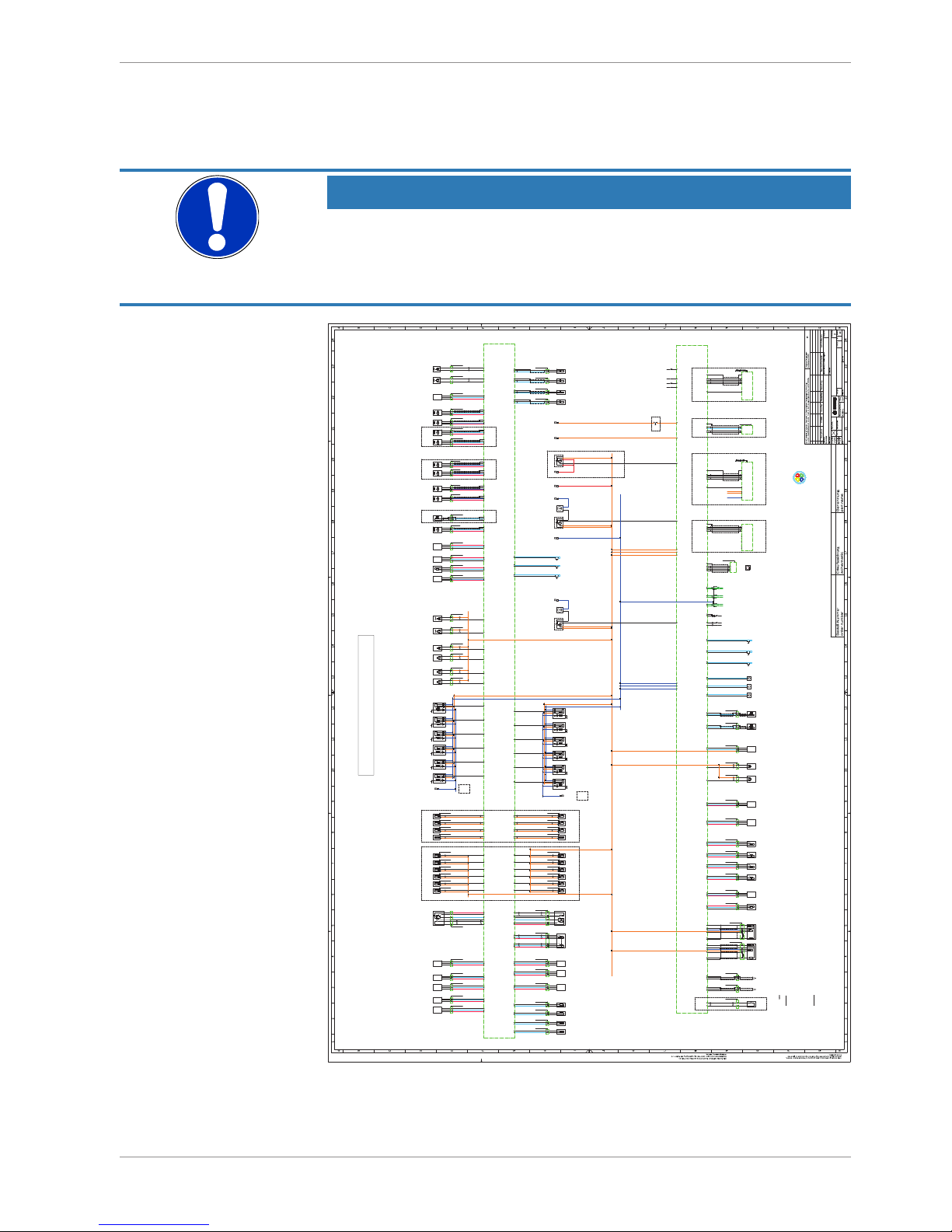
2.3.7 Harness / Wiring
The wiring diagram is available at Bosch Motorsport website on the MS 6 product page.
NOTICE
The wiring diagram shows a principle of wiring and connection options.
ECU pin relation may change to customer data application and program layout. Sensor-,
actuator- and power supplies may also change to the request of the project.
4 13 2
ENG GND
+
Kl.1
ECU GND
D261 205 336-01
4 13 2
ENG GND
+
Kl.1
ECU GND
D261 205 336-01
4 13 2
ENG GND
+
Kl.1
ECU GND
D261 205 336-01
4 13 2
ENG GND
+
Kl.1
ECU GND
D261 205 336-01
4 13 2
ENG GND
+
Kl.1
ECU GND
D261 205 336-01
4 13 2
ENG GND
+
Kl.1
ECU GND
D261 205 336-01
4 13 2
ENG GND
+
Kl.1
ECU GND
D261 205 336-01
4 13 2
ENG GND
+
Kl.1
ECU GND
D261 205 336-01
Cylinder 1
ignition
2,5mm²
1 2
Injection
valve
Cylinder D
.
1 2
Injection
valve
Cylinder C
.
1 2
Injection
valve
Cylinder B
.
1 2
Injection
valve
Cylinder A
.
1 2
.
.
camshaft
control in
cam
1 2
.
.
camshaft
control in2
cam 2
? ?
not def.
waste gate
control valve
increase bank1
wastegate inc b1
? ?
not def.
waste gate
control valve
increase bank2
wastegate inc b2
1 2
.
.
gearshift
actuator
upshift
upshift
1 2
.
.
gearshift
actuator
downshift
downshift
X1
2 1X2 3
fuel pump
relay.r/pump
AWG 14
fuel pump
not def.
pump
AWG 14
X12 1X2 3
main relay.r/main
AWG 8
M
+
-
5
+
S1
-
S2
H+
H-
electronic
throttle control
ath
34 6 1 2
electronic
throttle control 2
ath 2
M
+
-
5
+
S2
-
S1
H+
H-
31642
.
.
.
.
M
+
-
.
H+
H-
.
? ?
not def.
not def.
deliver
control
valve bank1
fcv 1
? ?
not def.
not def.
deliver
control
valve bank2
fcv 2
H-Bridge
3
oil
temperature
toil
??
not def.
not def.
fuel
temperature
tfuel
??
not def.
not def.
??
not def.
not def.
??
not def.
not def.
air
temperature
tint
engine
temperature
tmot
.
Signal
+-
oil
pressure
sensor
poil
.
.
?? ?
not def.
not def.
.
Signal
+-
P21
intake manifold
sensor
p21
.
.
?? ?
not def.
not def.
.
Signal
+-
.
.
?? ?
not def.
not def.
.
Signal
+-
.
.
?? ?
not def.
not def.
P21_2
intake manifold
sensor
p21_2
P22
intake manifold
sensor
after throttle
p22
.
Signal
+-
.
.
?? ?
not def.
not def.
P22_2
intake manifold
sensor
after throttle
p22_2
S+
-
S+
-
12 3 4 56
acceleration
pedal
sensor
aps
AS 007-35SN.
AS 607-35PN
launch
function
switch
B_LAUNCHSW
chassis function
reset
switch
B_CHASSISRESSW
pit
speed
switch
B_PITSPEEDSW
map
position
switch
MAPPOS
traction
control
switch
TC_STAGE
wet
switch
B_WET
Signal
+-
sensor
meas
K48
meas_K48
?? ?
not def.
not def.
l
a
n
g
i
S
+-
clutch
pressure
pclutch
?? ?
not def.
not def.
l
a
n
g
i
S
+-
laptrigger
beacon
laptrig
12 3
ASL 0-06-05-SD
ASL 6-06-05-PD
S+
-
gear
potentiometer
gear
.
.
?? ?
not def.
not def.
S+
-
gear shift
sensor
gearshift
.
?? ?
not def.
not def.
S+
-
free meas.
channel A78
meas_A78
.
?? ?
not def.
not def.
S
+ -
damper position
sensor
rear left
dam_rl
?? ?
.
not def.
not def.
S
+ -
damper position
sensor
rear right
dam_rr
?? ?
.
not def.
not def.
?? ?
not def.
not def.
Signal
+-
?? ?
not def.
not def.
brake
pressure
front
pbrake_f
gearbox
pneumatic
pressure
pgearair
?? ?
.
not def.
not def.
brake pressure
sensor
rear
pbrake_r
?? ?
.
not def.
not def.
S+
-
steering
angle
potentiometer
steer
.
.
?? ?
not def.
not def.
. . .
.
.
exhaust gas
temp. sensor1
texh
.
.
exhaust gas
temp. sensor2
texh 2
. . .
a_camctrl_out
cam out
position
a_camctrl
cam in
position
a_camctrl_out2
cam2 out
position
+ S
-
?? ?
.
.
+ S
-
+ S
-
?? ?
.
.
?? ?
.
.
+
-
crankshaft
signal
nmot
N
S
?? ?
.
.
wheel
speed _fr
vwheel_fr
wheel
speed_fl
vwheel_fl
wheel
speed_rr
vwheel_rr
wheel
speed_rl
vwheel_rl
+ S
-
?? ?
not def.
not def.
+ S
-
?? ?
not def.
not def.
+ S
-
?? ?
not def.
not def.
+ S
-
?? ?
not def.
not def.
knock
sensor 1
bank 1
KNOCK1B1
knock
sensor 2
bank 1
KNOCK2B1
2112
.
.
knock
sensor 1
bank 2
KNOCK1B2
knock
sensor 2
bank 2
KNOCK2B2
2112
.
.
not def.
not def.
not def.
not def.
not def.
not def.
not def.
not def.
+ -
turbo
speed
nTurbo
N
S
?? ?
not def.
not def.
+ -
N
S
?? ?
not def.
not def.
163119171536
5538
9091
48 33
47
3534322050
78797677
37 36 91 92
41538990
82
58 5960 61
43
20
64
20
2
20
23
20
3
20
24
20
46
20
67
20
26
95 21 97 93
85 86 87 88
39 77 7838
40
7574
50 49 50 51 52
1713 14 15 16
4562
shiftupswitch
upsw
shift
down
switch
dnsw
76 57
+ S
-
.
.
47
crankshaft
signal
nmot
1 2
Injection
valve
Cylinder E
.
1 2
Injection
valve
Cylinder F
.
2
Injection
valve
Cylinder H
.
1 2
Injection
valve
Cylinder G
.
44
20
65
20
1
20
22
20
4
20
25
20
45
20
66
20
ground terminal
29
CAN_H
12
CAN_L
28
CAN_H
11
CAN_L
27
CAN_H
10
CAN_L
52
RX
53
TX
44
43
4241
B_D_ETH2Rx+
61
B_D_ETH2Rx-
60
B_D_ETH2Tx+
59
B_D_ETH2Tx-
58
B_D_USB_DP
25
B_D_USB_DN
24
G_G_USB_GND
07
O_V_USB_VBUS
08
51
30 13 37
06
14
05
14
03
14
75
20
04
14
02
14
01
14
89
GNDUSBSCR
09
SCN_DATA
26
ground terminal
41 32
USB Buchse
.
USB
data
stick
USB
57
68
3
42
1
RJ-45 Buchse
Ansicht von hinten
36 12
pair_1
pair_2
Ethernet wire
RJ45 ETH Buchse
2121
8181818081
828282828282
82 82
6364
6565
62626262
6262626262
62 626262
17 17 17
7
7
1111
09
09
5
5
xx xx
ETH1_RX+
ETH1_RX-
ETH1_TX+
ETH1_TX-
x
SYNC IN
shield
x
SP/DDU8/C60
AS DD 6-12-41-SN
.
DDU8/C60
Display DDU S2 Plus
AS 6-14-35-SN
DDU S2+
pair_1
pair_2
Ethernet wire
26
pair_1
pair_2
B_F_TIMESYNC
14
2121
4662
54
20
6
12
0606
06
27 28 29
68 69 70 71
OPTIONAL ETHERNET EXTENSION
1 2
.
.
camshaft
control out
cam out
1 2
.
.
camshaft
control out2
cam out 2
102 94
06 08 08
2,5mm²
power supply
ground terminal
ecu
interface
DIAG
57
AWG 8
72
Starter output
5 4847
a_camctrl2
cam2 in
position
+ S
-
.
.
49625 5
OPTIONAL
OPTIONAL
for inductive sensor
LIN-BUS
GND_engine
rc 8mm blue
GND_ENG
short
connection
to
engine block
GND_engine
rc 8mm blue
GND_ENG
F02U.S00.444-03
Basisanschluss MS6F02U.S00.444-03
MS6 Basic Wiring
Achtung : - alle nicht bezeichneten Leitungen sind auf AWG
24 ausgelegt
- kleine Buchstaben sind unterstrichen
- rc = Ringverbinder
- Ethernetkabel mit Spec. CAT5 verwenden
- Firewirekabel nach Standard IEE1394
- jede CAN Verbindung muss mit 60Ω abgeschlossen sein
- bei USB und Ethernetleitung unbedingt auf Paare achten
- Ethernetverkabelung muss seperat geführt werden
- Kabelquerschnitte müssen nach Bedarf angepasst werden
Attention : - all not marked wire´ are AWG24
- small letters are underlined
- rc = ringwire
- use ethernetcable CAT5
- firewirecable as spec IEE1394
- all CAN networks must be terminated with 60Ω
- please respect strictly the pairs while using datawires like USB or Ethernet
- ethernet wire´s must be wired separately
- wire diametre must be adapted depending on usage
short
connection
to
engine block
power supply
ENGINE
on/off
switch
B_ENGON_IN
F02U.B00.712-01
?? ??? ?
OPTIONAL
4 13 2
ENG GND
+
Kl.1
ECU GND
D261 205 336-01
4 13 2
ENG GND
+
Kl.1
ECU GND
D261 205 336-01
30 31
4 13 2
ENG GND
+
Kl.1
ECU GND
D261 205 336-01
4 13 2
ENG GND
+
Kl.1
ECU GND
D261 205 336-01
Cylinder 2
ignition
Cylinder 3
ignition
Cylinder 4
ignition
Cylinder 5
ignition
Cylinder 6
ignition
Cylinder 7
ignition
Cylinder 8
ignition
Cylinder 9
ignition
Cylinder 11
ignition
Cylinder 12
ignition
Cylinder 10
ignition
72 7354
.
l
a
n
g
i
S
+-
fuel
pressure high
sensor 2
prail 2
.
.
?? ?
not def.
not def.
.
Signal
+-
fuel
pressure high
sensor 1
prail
.
.
?? ?
not def.
not def.
.
Signal
+-
fuel
pressure low
sensor
pfuel
.
.
?? ?
not def.
not def.
8079817 57 06
1
1 2
Injection
valve
Cylinder 4
.
1 2
Injection
valve
Cylinder 3
.
1 2
Injection
valve
Cylinder 2
.
1 2
Injection
valve
Cylinder 1
.
1 2
Injection
valve
Cylinder 5
.
1 2
Injection
valve
Cylinder 6
.
98 100 101 96 99 103
1 2
Injection
valve
Cylinder 10
.
1 2
Injection
valve
Cylinder 9
.
1 2
Injection
valve
Cylinder 8
.
1 2
Injection
valve
Cylinder 7
.
1 2
Injection
valve
Cylinder 11
.
1 2
Injection
valve
Cylinder 12
.
42 105 18 20 63 84
OPTION INJECTION LOW PRESSURE OPTION INJECTION HIGH PRESSURE
F02U.B00.711-01
OPTIONAL USB Data Stick
01
Anlage
20140718 HtM . .
BEG/EMS3
.
Connector "A"
AWG 14
AWG 14
AWG 14
10mm2
Kl.30_Motronic
rc 8mm red
Kl.30_Motronic
power supply
OPTIONAL with MAIN RELAY
AWG 14
AWG 14
AWG 14
Signal
+-
Signal
+-
1210 10 510 510
510 510 5 10 51012 12
5 512
12 12
Kl.31
rc 8mm blue
GND
08 0811110909
32 0633 34 35 08 08 06 08 08
OPTIONAL
S
+ -
damper position
sensor
front right
dam_fr
64 64 64
?? ?
not def.
not def.
1881
S
+ -
damper position
sensor
front left
dam_fl
64
82
CAN wire
CAN wire
CAN wire
26
CAN 3
CAN 2
CAN 1
ext. components with
function request
(gearcontrol, steeringwheel,..)
Components Bosch Motorsport
(ABS,PBX90,MSA-Box,Bypass,HPI)
ext. components
(measure components)
useable for options like
- alternator control
- wiper control
RS232
useable for options like
- telemetry
Connector "K"
LS 1AMP
TRIGGERWHEEL_SIGNAL Output
FLYWHEEL_SiGNAL Output
RPM SIGNAL Output
20150210 HtM
Kl.30_Motronic
rc 8mm red
Kl.30_Motronic
D261.205.356-01
.
twisted pair
twisted pair
236987882286
70716885
lambda sensor Bank1
D261.205.356-01
LSU 4.9
lam_1
1
6
5
234
Nernst
Pump
D261.205.356-01
.
lambda sensor Bank2
D261.205.356-01
LSU 4.9
lam_2
1
6
5
234
Nernst
Pump
twisted pair
twisted pair
2121
turbo
speed 2
nTurbo2
20150218 HtM
9816
CAN1_low
4
CAN1_high
22
SCREEN
10
K LINE
3
Unit_GND
1
PERM.POS.
2
SW .POS.
15
ecu interface
(MSA-Box2)
AS 012-35SN
DIAG
12
11
TERM 15 PIN
ETH_RXETH_RX+
ETH_TX-
ETH_TX+
44
43
4241
26
pair_1
pair_2
Ethernet wire
OPTIONAL DDUS2 PLUSOPTIONAL DIAG
AWG 8
AWG 20
M
+
-
X12 1X2 3
air conditoin
compressor relay
.
R/GEARAIR
AWG 14
air
compressor
not def.
AC
AWG14
AWG 14
56
08
reverse
gear
shift switch
reverse
5512
.
6mm2
.
.
tbd.
tbd.
tbd.
tbd.
tbd.
tbd.
tbd.
+-+-
RED
Tx+
BLUE
Tx-
Yellow
Rx+
GREEN
Rx-
Ethernetwire
4x AWG24
Min bend radius:
dyn: 47mm
stat: 24mm
56
not def.
not def.
not def.
not def.
.
.
not def.
not def.
update APIX
+12V
digital power supply
rc 8mm red
+12V
+12V
engine on sw
rc 8mm red
+12V
AWG 20
RESPECT WIRE SPEC/LENGTH !
- use the right SPECed wire signed
"Ethernetwire"
AWG 20
- twisted / twisted pair
update
Kl.31
rc 8mm blue
GND
M
+
-
AWG 14
AWG14
Kl.31
rc 8mm blue
GND
USB/Ethernet wire
RESPECT WIRE SPEC !
- use the right SPECed wire signed
"Ethernetwire"
- take care about the wire orientation
RESPECT WIRE SPEC !
- use the right SPECed wire signed
"Ethernetwire"
RESPECT WIRE SPEC !
- use the right SPECed wire signed
"Ethernetwire"
RESPECT WIRE SPEC !
- use the right SPECed wire signed
"Ethernetwire"
02
20150505 HtM
update DDU S2+
03
B_D_ETH2Rx+
61
B_D_ETH2Rx-
60
B_D_ETH2Tx+
59
B_D_ETH2Tx-
58
SCN_DATA
26
924 1025
ETH1_RX+
ETH1_RX-
ETH1_TX+
ETH1_TX-
28
SYNC IN
shield
22
pair_1
pair_2
Ethernet wire
B_F_TIMESYNC
14
3
+12V Supply
4
GND
32
+12V Supply
GND
+12V Supply
+12V Supply
Y:\Fertigung\25_Zeichnungen\Kabel\Anschlusspläne_Kabelbäume_F\A CAD Anschlusspläne Kabelbäume_F\F02U_S00_444_03_Basisanschlussplan_MS6_Offiziel.dwg, 05.05.2015 10:11:46, DWG To PDF.pc3
2 | Technical Data
22/76 Engine_Control_Unit_MS_6.x_Manual Bosch Motorsport
Harness connectors
Bosch automotive connectors are not available as complete set of components, so Bosch
Motorsport itself offers such a package. For more technical details please check Boschconnector homepage, 196 pins
http://www.bosch-connectors.com/bogscoca/category/142
MS 6 harness connector type A (105 contacts), coding variant 1
F 02U B00 712-01
MS 6 harness connector type K ( 91 contacts), coding variant 1
F 02U B00 711-01
Protection Classification IP X6K, X8, X9K
Temperature range -40 to 120°C
Shakeproofed Max. 3.4 g
Wiring diameter 0.35 to 2.5 mm²
Pinsize 1.2 mm; 2.8 mm
Dummy Plug
Dummy plug 1 928 405 459 for unused connections
Matrix 1.2 / CB / 0.75 to 1.0 mm²
Dummy plug 1 928 405 460 for unused connections
Matrix 1.2 / CB / 1.0 - 1.5 mm²
Dummy plug 1 928 301 207 BTL 2.8
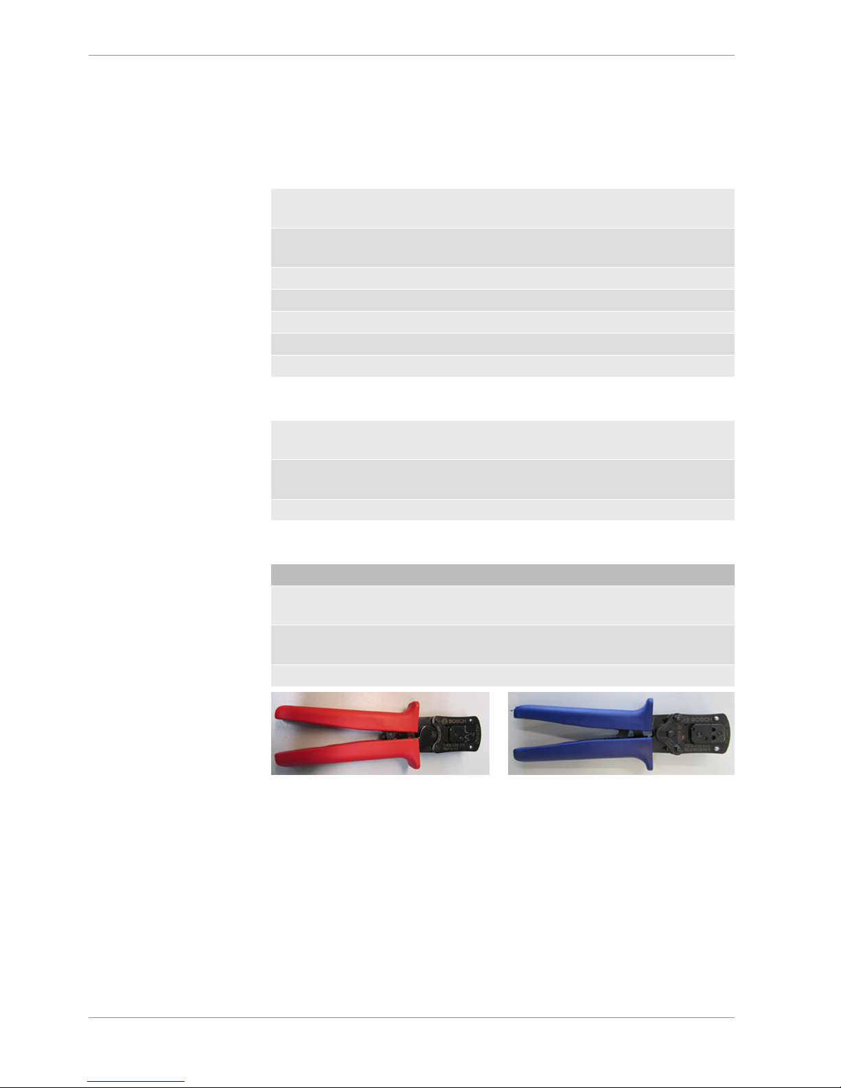
Tools and Contacts
Tool Matrix Contact Wire size
1928498212 Matrix 1.2 Clean Body
1928.498.991
0.35 to 0.5 mm²
1928498213 Matrix 1.2 Clean Body
1928.498.992
0.75 to 1.0 mm²
1928498837 1928498840 BTL 2.8 1928.498.651 1.5 to 2.5 mm²
Wiring
Bosch Motorsport recommends using the specified cable material and harness layout for
automotive connectors and wiring applications.
For Ethernet and USB connection CAT5 specified material is recommended and the pairs
and shield connections have to be strictly respected as shown in the wiring diagram.
For USB, the maximum wiring length is limited to 3 m and it is not allowed to be included
into a common harness and also there is no interruption allowed.
Due to installation condition, the length may have to be reduced.
Keep network wiring in distance to main sources of electrical noise like coils, coil- and HPinjector wirings and also in distance to any telemetry transmitter.

Technical Data | 2
Bosch Motorsport Engine_Control_Unit_MS_6.x_Manual 23/76
CAN-networks need a 120 Ohm termination at 2 ends of the wiring.
The MS 6 is able to switch on an internal 120 Ohm termination, set CWCANx_TERM true
to enable the termination.
For wiring layout, respect the common rules of failure reduction like separated sensor
power supply between important system sensors (e.g. camshaft detection) and measure
options (e.g. damper position).
Be ensure HP-injectors, electronic throttles and other high frequently switched actuators
are connected within the wiring limits of 2.5 m and all wires are manufactured as twisted
pairs.
If using a preinstalled production harness, first verify the way of sensor- and actuator controls.
Often production parts have to be connected to 12 V power supply and actuators are
controlled in different ways. The production harness may need to be modified.
Office harness
Reduced layout to realize communication between PC, MS 6 device and Display DDU, recommended for flash configuration, display configuration and installation tasks. Bosch
Motorsport part number: F 02U V01 809
2.3.8 Ignition Trigger Wheel
To detect the engine position and to calculate the exact crankcase position, the system assumes toothed trigger wheels for proper operation. Recommended is to use 60 (-2) teeth
for the flywheel and one teeth for the camshaft detection. Modifications of the mechanical
designs are possible, such as using quick-start production designs for the camshaft or different number of teeth for the flywheel (limited to 30 to 60 teeth).
NOTICE
Less number of teeth reduces the accuracy of the system angle measurement.
Not usable are flywheels with 4-1 or 6-1 teeth. Please follow the description below as recommendation for the mechanical dimensions.
Recommended values:
– D = min. 160 mm
– h1 = 3.5 mm
– h2 = h1/2 (important for the use of inductive sensor)
– LSKW = 0.8 mm +/- 0.3 mm
– t = min. 5 mm
– LNSW = 1.0 mm +/- 0.5 mm
 Loading...