

Bosch MS 3 Sport GT3 Cup User Manual
Engine Control Unit MS 3 Sport GT3 Cup
Manual
Version 1.2 17/04/2019

Content
ii/24 Engine_Control_Unit_MS_3_Sport_GT3_Cup_Manual Bosch Motorsport
Content
1 Getting started ................................................................................................................................................................ 3
2 Sport Systems - Overview.............................................................................................................................................. 4
3 Technical Data................................................................................................................................................................. 5
3.1 Input channels ....................................................................................................................................................................................................... 5
3.2 Output channels.................................................................................................................................................................................................... 5
3.3 Power supply.......................................................................................................................................................................................................... 7
3.4 Ignition trigger wheel ......................................................................................................................................................................................... 8
3.5 Sensor recommendation ................................................................................................................................................................................... 11
4 Starting up the ECU ........................................................................................................................................................ 12
4.1 Offline Data Application .................................................................................................................................................................................... 12
4.2 Online Data Application..................................................................................................................................................................................... 18
4.3 Activation of Software Options....................................................................................................................................................................... 21
5 Extensibility ..................................................................................................................................................................... 22

Getting started | 1
Bosch Motorsport Engine_Control_Unit_MS_3_Sport_GT3_Cup_Manual 3/24
1 Getting started
Disclaimer
Due to continuous enhancements we reserve the rights to change any illustrations, photos
and technical data within this manual. Please retain this manual for your records.
Before starting
Before starting your engine for the first time, install the complete software from the installation CD. Bosch Motorsport software is developed for Windows 2000/XP. Connect the
PC Link Adapter (MSA Box II) or the Ethernet line (depending on calibration equipment) to
your computer and install the driver. Read the manual carefully and follow the application
hints step by step. Don’t hesitate to contact us, contact data can be found on the back
side of this document.
NOTICE
The Bosch Motorsport MS 3 Sport GT3 Cup was developed for use by professionals and
requires in depth knowledge of automobile technology and experience in motorsport. Using the system does not come without its risks.
It is the duty of the customer to use the system for motor racing purposes only and not
on public roads. We accept no responsibility for the reliability of the system on public
roads. In the event that the system is used on public roads, we shall not be held responsible or liable for damages.
Any maintenance or repair must be performed by authorized and qualified personnel approved by Bosch Motorsport.
2 | Sport Systems - Overview
4/24 Engine_Control_Unit_MS_3_Sport_GT3_Cup_Manual Bosch Motorsport
2 Sport Systems - Overview
The Sport Systems support an easy to understand user concept. The MS 3 Sport GT3 Cup
is configured as an alpha/n version. This means that the engine characteristic map is
based on engine speed, throttle position and engine temperature. The injected amount of
fuel and the ignition point are derived from these values.
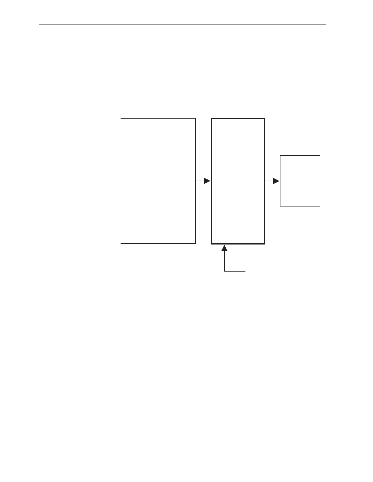
The drawing gives you an overview over the essential input and output channels of a MS 3
Sport GT3 Cup that are necessary to run the engine.
Engine Control Unit
Camshaft teeth sensor
Crankshaft teeth sensor
Lambda sensor
Throttle valve position potentiometer
Fuel temperature sensor
Engine oil temperature sensor
Ambient pressure sensor
Intake air temperature sensor
Knock sensor
Accelerator pedal sensor
(only with Egas)
. . .
Input signals Output signals
Power supply
Fuel injectors A-F
Ignition coils A-F
Electronic throttle
body (only with Egas)
. . .
Illustration1: Input and output channels

Technical Data | 3
Bosch Motorsport Engine_Control_Unit_MS_3_Sport_GT3_Cup_Manual 5/24
3 Technical Data
3.1 Input channels
Input channels for temperature sensors
Temperature inputs have an internal “pull up” resistor for use with a NTC sensor (negative
temperatur coefficient). These pull ups can be switched software specifically. Depending
on the used sensor (e.g. 15 kOhm or 2.5 kOhm NTC) the corresponding linearization curve
has to fit.
For example
– tmot (engine temperature)
– tair (intake air temperature)
Input channels for voltage sensors
For measuring of throttle positions or pressures which deliver a voltage (active sensors),
pull up resistors are not necessary. These sensors must be calibrated with the sensors offset and sensitivity values (printed on the sensor, if it is from Bosch).
For example
– ath (throttle position)
– pfuel (fuel pressure)
– poil (oil pressure)
Input channels for inductive speed sensors
In the default configuration the MS 3 Sport GT3 Cup needs an inductive speed sensor on
the ignition trigger wheel.
Input channels for Hall-effect-speed sensors
For the camshaft signal a Hall-effect sensor is necessary. Also for wheel speed measurement Hall-effect sensors are recommended. Four Hall-effect wheel speed sensors can be
connected directly to the ECU. Different hardware configurations are available on request.
Input channels for Lambda measurement and control
For wide range Lambda measurement and control we recommend a Lambda sensor of the
Bosch LSU series.
3.2 Output channels
There are 6 independent injection output stages for the injection. These injection output
stages can take a maximal current of 2.2 Ampere. Therefore the injection valves must have
a resistance of at least 6 Ohm.
NOTICE
Don’t use Bosch injection valves with 1.2 Ohm.
A few Bosch injection valves have an internal resistance of just 1.2 Ohm. These types can
not be used here.
3 | Technical Data
6/24 Engine_Control_Unit_MS_3_Sport_GT3_Cup_Manual Bosch Motorsport
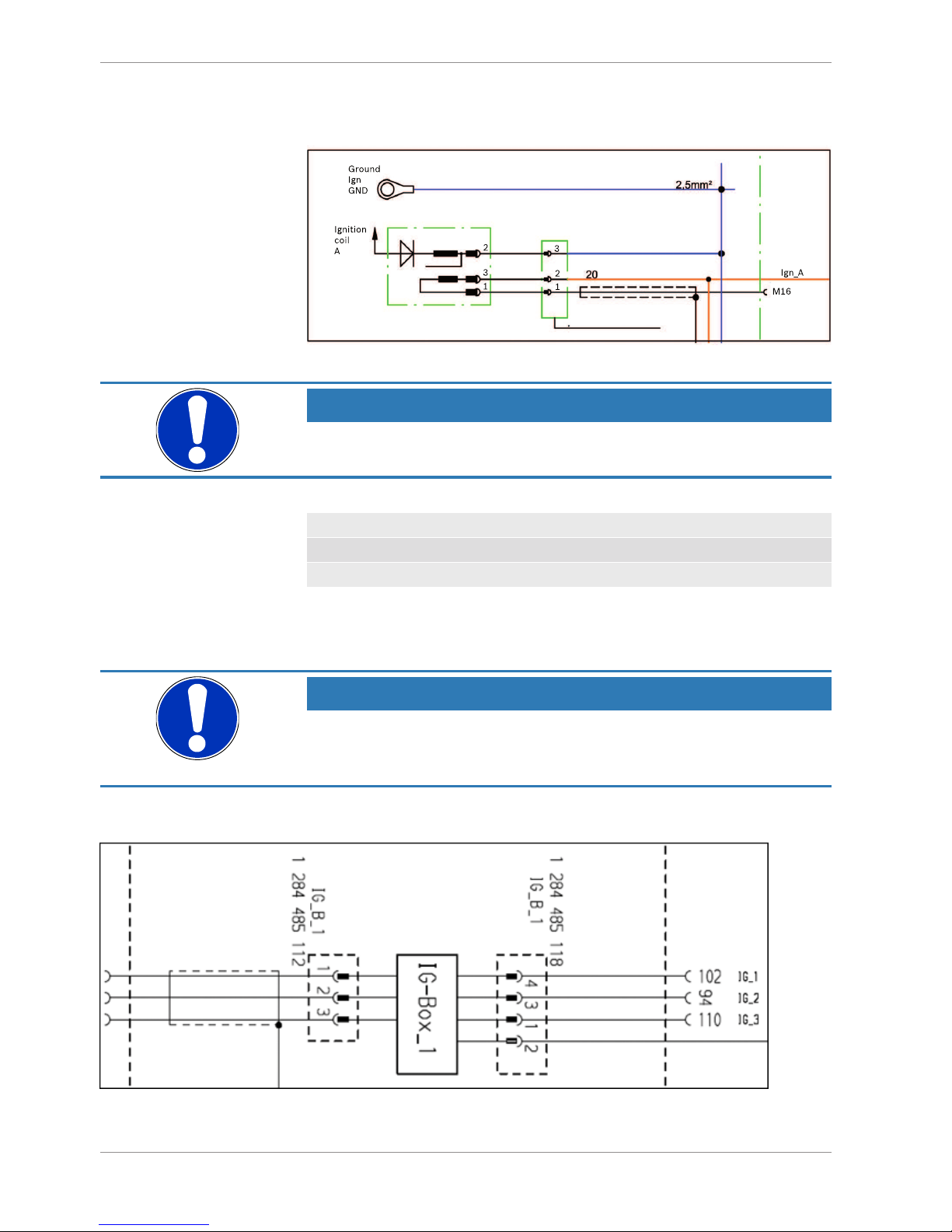
The MS 3 Sport GT3 Cup has integrated ignition power stages. The wiring is shown in the
following picture.
Illustration2: Integrated ignition power stage
NOTICE
In case of ignition-caused malfunctions, please use screened sensor wires.
A typical 6 cylinder engine with firing order 1-5-3-6-2-4 is connected as follows:
Firing 1 5 3 6 2 4
IGN A B C D E F
INJ A B C D E F
There are max. 6 independent injection output stages for the injection. These injection
output stages can take a maximal current of 2.2 Ampere. Therefore the injection valves
must have a resistance of at least 6 Ohm.
NOTICE
Don’t use Bosch injection valves with 1.2 Ohm.
A few Bosch injection valves have an internal resistance of just 1.2 Ohm. These types can
not be used here.
The MS 3 Sport GT3 Cup has integrated ignition drivers. The wiring is shown in the following picture.
Illustration3: Integrated ignition drivers

Technical Data | 3
Bosch Motorsport Engine_Control_Unit_MS_3_Sport_GT3_Cup_Manual 7/24
NOTICE
In case of ignition-caused malfunctions, please use screened sensor wires.
A typical 6 cylinder engine with firing order 1-5-3-6-2-4 is connected as follows:
Firing 1 5 3 6 2 4
IGN A B C D E F
INJ A B C D E F
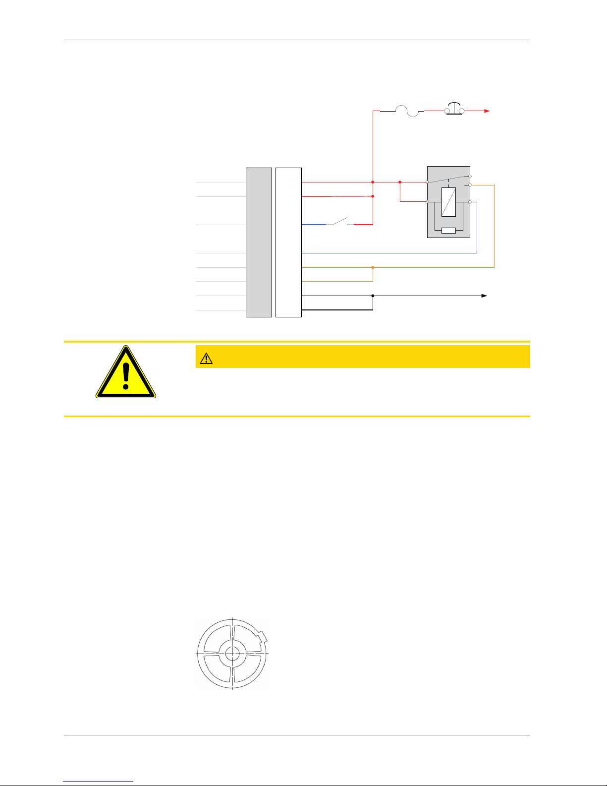
3.3 Power supply
The MS 3 Sport GT3 Cup requires an external main relay to be wired to the harness. This
relay is controlled by the MS 3 Sport GT3 Cup to realize that important information can be
stored after switching off the ignition.
Please ensure that you have a good ground installation. That means:
– A ground that has a solid, low resistance connection to the battery minus terminal
– Connection should be free from dirt, grease, paint, anodizing, etc.
– Cylinder heads make a good grounding point
– Use large diameter wire.
– More metal-to-metal contact is better
Connection of the power supply
The following notations for power signals are used:
– KL15 is a switched battery rail controlled by the ECU driver.
– KL30 is an unswitched battery positive rail (same as battery positive terminal).
– KL31 is an unswitched ground rail (same as battery negative terminal).
3 | Technical Data
8/24 Engine_Control_Unit_MS_3_Sport_GT3_Cup_Manual Bosch Motorsport
85
30
87a
87
86
Bosch Automotive relay
Fuse / Circuit breaker
KL30
KL15
To battery plus (+)
Master kill switch
Ignition switch
Notes:
- ECU requires a dedicated relay to be installed in the car
- KL30 is HAAT (Hot At All Times)
- KL15 is hot only when ECU engages relay
- ECU will engage relay after 12V is detected on pin ‘J’ by pulling pin ‘B’ to ground
-
ECU will disengage the relay after 12V is removed from pin ‘J’,
but may be delayed for up to 2 seconds after engine speed signal is zero.
- It is recommended to fuse the KL30 circuit
- Wire gauge recommendations based on Raychem Spec 44 wire
KL30
KL15
KL15 IN
Main relay
KL31
KL31
To battery minus (-)
14ga
20ga
20ga
14ga
20ga
20ga
20ga
16ga
16ga
16ga
16ga
14ga
14ga
F
H
B
C
G
L
M
J
Spec
harness
connector
ECU
Illustration4: Power supply connection plan
CAUTION
Wrong polarity / high currents
Wrong polarity of the terminals and high currents damage the MS 3 Sport GT3 Cup. Be
careful to observe current limits of wires and connector pins!
3.4 Ignition trigger wheel
To start the engine, the ECU requires information about the position of the camshaft and
crankshaft. These are determined by using sensors on the cam and crankshaft generator
gear.
In this chapter you’ll find the sensors you need to detect the camshaft and crankshaft position and how to tune the components to each other.
3.4.1 Camshaft and Crankshaft Sensors
Camshaft trigger sensor
The camshaft trigger sensor is a Hall-effect type with a single tooth trigger wheel. Bosch
Motorsport recommends the use of Hall-effect sensor HA-P.
Illustration5: Camshaft wheel
 Loading...