

Page 1
MIC IP starlight 7000 HD, MIC IP dynamic
7000 HD
MIC71xx, MIC72xx
en Operation Manual
Page 2

Page 3

MIC IP starlight 7000 HD, MIC IP
dynamic 7000 HD
Table of contents
Table of Contents | en 3
1
1.1 About this Manual 6
1.2 Legal Information 6
1.3 Safety Precautions 6
1.4 Important Safety Instructions 6
1.5 Important Notices 8
1.6 Important Notices - Illumination Safety 11
1.7 Customer Support and Service 12
2
2.1 Parts List - Camera 13
2.2 Additional Tools 13
3
4
5
6
7
7.1 Select the Mounting Location 18
7.2 Select the Mounting Orientation 19
8
9
10
10.1 About Camera Power and Control 25
10.2 Power Source Options 25
10.3 Ethernet Connections 26
10.4 Camera Connections 27
10.5 Connect the Camera to the Network 28
11
12
12.1 Typical IP Configuration with 95 W midspan (no I/O connections) 34
12.2 Typical Configuration with MIC-ALM-WAS-24 35
12.3 Typical IP Configuration with NPD-PSU-HPOE 36
13
13.1 System Requirements 37
13.2 Configuring the Camera 38
13.2.1 Using the Configuration Manager 38
13.2.2 Using the MIC7000 Series Web Server 38
13.2.3 About the SETTINGS Page 40
13.3 Configuring Audio (Optional) 41
14
14.1 Basic Mode: Device Access 42
14.2 Basic Mode: Date/Time 42
14.3 Basic Mode: Network 43
14.4 Basic Mode: Encoder 43
14.5 Basic Mode: Audio 44
14.6 Basic Mode: Recording 44
14.7 Basic Mode: System Overview 45
Safety 6
Unpacking 13
Product Description 14
Overview of Installation Steps 15
Configuration Programming in the Shipping Box 16
Configuration Programming on a Temporary Table-top Stand 17
Mounting Location and Mounting Orientation 18
Overview of Mounting Options 21
Install the Camera 24
Make Connections - Power and Control 25
Cant the Camera 29
Typical System Configurations 34
Configuration 37
Configuration via IP, Basic Mode 42
Bosch Security Systems, Inc. Operation Manual 2014.05 | 1.0 | F.01U.291.520
Page 4

4 en | Table of Contents
MIC IP starlight 7000 HD, MIC IP
dynamic 7000 HD
15
Configuration via IP, Advanced Mode 46
15.1 Advanced Mode: General 46
15.2 Identification 46
15.3 Password 46
15.4 Date/Time 47
15.5 Display Stamping 48
15.6 Advanced Mode: Web Interface 49
15.7 Appearance 49
15.8 LIVE Functions 50
15.9 Logging 51
15.10 Advanced Mode: Camera 52
15.11 Installer Menu 52
15.12 Encoder Profile 53
15.13 Encoder Streams 55
15.14 Privacy Masks 57
15.15 Picture Settings 57
15.16 Lens Settings 60
15.17 PTZ Settings 61
15.18 Illumination/Wiper 62
15.19 Scenes and Tours 63
15.20 Sectors 64
15.21 Miscellaneous 64
15.22 Audio 64
15.23 Pixel Counter 65
15.24 Advanced Mode: Recording 65
15.25 Storage Management 65
15.26 Recording Profiles 67
15.27 Maximum Retention Time 68
15.28 Recording Scheduler 68
15.29 Recording Status 69
15.30 Advanced Mode: Alarm 69
15.31 Alarm Connections 69
15.32 VCA 71
15.33 Virtual Masks 75
15.34 Audio Alarm 76
15.35 Alarm E-Mail 76
15.36 Alarm Task Editor 77
15.37 Alarm Rules 78
15.38 Advanced Mode: Interfaces 78
15.39 Alarm Inputs 78
15.40 Alarm Outputs 78
15.41 Advanced Mode: Network 79
15.42 Network Access 79
15.43 DynDNS 81
15.44 Advanced 82
15.45 Network Management 82
15.46 Multicast 83
15.47 Image Posting 84
15.48 Accounts 85
2014.05 | 1.0 | F.01U.291.520 Operation Manual Bosch Security Systems, Inc.
Page 5

MIC IP starlight 7000 HD, MIC IP
dynamic 7000 HD
Table of Contents | en 5
15.49 IPv4 Filter 85
15.50 Encryption 86
15.51 Advanced Mode: Service 86
15.52 Maintenance 86
15.53 Licenses 87
15.54 Diagnostics 87
15.55 System Overview 88
16
Operation 89
16.1 LIVE Page 89
16.1.1 View Control 90
16.1.2 AUX Control 91
16.1.3 Special Functions 93
16.1.4 Digital I/O 93
16.1.5 System Log/Event Log 94
16.1.6 Audio 94
16.1.7 Saving snapshots 94
16.1.8 Recording 95
16.1.9 Playback 95
16.2 Using Intelligent Tracking 97
16.3 Recommended Use of Your MIC Camera 100
17
18
19
Troubleshooting 101
Maintenance 103
Decommissioning 104
19.1 Transfer 104
19.2 Disposal 104
20
21
Technical data 105
Keyboard Commands By Number 106
Bosch Security Systems, Inc. Operation Manual 2014.05 | 1.0 | F.01U.291.520
Page 6
!
!
!
6 en | Safety
MIC IP starlight 7000 HD, MIC IP
dynamic 7000 HD
1
1.1
1.2
1.3
Safety
About this Manual
This manual has been compiled with great care and the information it contains has been
thoroughly verified. The text was complete and correct at the time of printing. Because of the
ongoing development of products, the content of the manual may change without notice.
Bosch Security Systems accepts no liability for damage resulting directly or indirectly from
faults, incompleteness, or discrepancies between the manual and the product described.
Legal Information
Copyright
This manual is the intellectual property of Bosch Security Systems, Inc. and is protected by
copyright. All rights reserved.
Trademarks
All hardware and software product names used in this document are likely to be registered
trademarks and must be treated accordingly.
Safety Precautions
In this manual, the following symbols and notations are used to draw attention to special
situations:
Danger!
High risk: This symbol indicates an imminently hazardous situation such as “Dangerous
Voltage” inside the product. If not avoided, this will result in an electrical shock, serious bodily
injury, or death.
1.4
Caution!
Medium risk: Indicates a potentially hazardous situation. If not avoided, this may result in
minor or moderate injury. Alerts the user to important instructions accompanying the unit.
Caution!
Low risk: Indicates a potentially hazardous situation. If not avoided, this may result in
property damage or risk of damage to the unit.
Notice!
This symbol indicates information or a company policy that relates directly or indirectly to the
safety of personnel or protection of property.
Important Safety Instructions
Read, follow, and retain all of the following safety instructions. Heed all warnings on the unit
and in the operating instructions before operation.
Caution!
TO REDUCE THE RISK OF ELECTRIC SHOCK, DISCONNECT THE POWER SOURCE WHILE
INSTALLING THE CAMERA.
2014.05 | 1.0 | F.01U.291.520 Operation Manual Bosch Security Systems, Inc.
Page 7
!
!
!
!
MIC IP starlight 7000 HD, MIC IP
dynamic 7000 HD
Warning!
INSTALLATION SHOULD BE CARRIED OUT BY QUALIFIED PERSONNEL ONLY, IN
ACCORDANCE WITH THE NATIONAL ELECTRIC CODE, ANSI/NFPA, CANADIAN ELECTRICAL
CODE, AND ALL LOCAL COUNTRY CODES.
Warning!
INSTALL EXTERNAL INTERCONNECTING CABLES IN ACCORDANCE TO NEC, ANSI/NFPA70
(FOR US APPLICATION) AND CANADIAN ELECTRICAL CODE, PART I, CSA C22.1 (FOR CAN
APPLICATION) AND IN ACCORDANCE TO LOCAL COUNTRY CODES FOR ALL OTHER
COUNTRIES. BRANCH CIRCUIT PROTECTION INCORPORATING A 20 A, 2-POLE LISTED
CIRCUIT BREAKER OR BRANCH RATED FUSES ARE REQUIRED AS PART OF THE BUILDING
INSTALLATION. A READILY ACCESSIBLE 2-POLE DISCONNECT DEVICE WITH A CONTACT
SEPARATION OF AT LEAST 3 mm MUST BE INCORPORATED.
Warning!
ROUTING OF EXTERNAL WIRING MUST BE DONE THROUGH A PERMANENTLY EARTHED
METAL CONDUIT.
Safety | en 7
Warning!
THE CAMERA MUST BE MOUNTED DIRECTLY AND PERMANENTLY TO A NON-COMBUSTIBLE
SURFACE.
– Do not place a canted (45°) camera upright; it can fall over easily. Place the canted
camera on its side.
– Do not open the camera unit. Doing so will invalidate the warranty.
Use common-sense safety precautions, especially in situations where there could be risk of
injury if any part of the assembly becomes detached and falls. Bosch recommends using the
hinged DCA, which allows installers to “hang” the MIC camera temporarily on the DCA to
make electrical connections, before bolting the camera to the DCA.
– Ensure that the unit case is properly earthed. If the product is likely to be struck by
lightning, ensure that earth bonding connections are made correctly to the mounting of
the base of the unit.
– Do not manually back drive the pan or tilt axis of the camera. Doing so will damage the
motor drive gear train and will invalidate the warranty.
– Before transporting, supply power to the camera and rotate the ball so that the window
points toward the base. This will help to protect the wiper and the window during transit.
Bosch Security Systems, Inc. Operation Manual 2014.05 | 1.0 | F.01U.291.520
Page 8
8 en | Safety
MIC IP starlight 7000 HD, MIC IP
dynamic 7000 HD
1.5
Important Notices
Notice!
This device is intended for use in public areas only.
U.S. federal law strictly prohibits surreptitious recording of oral communications.
Accessories - Do not place this unit on an unstable stand, tripod, bracket, or
mount. The unit may fall, causing serious injury and/or serious damage to
the unit. Use only with mounting solutions specified by the manufacturer.
When a cart is used, use caution and care when moving the cart/unit
combination to avoid injury from tip-over. Quick stops, excessive force, or
uneven surfaces may cause the cart/unit combination to overturn. Mount the
unit per the installation instructions.
Adjustment of controls - Adjust only those controls specified in the operating instructions.
Improper adjustment of other controls may cause damage to the unit.
All-pole power switch - Incorporate an all-pole power switch, with a contact separation of at
least 3 mm in each pole, into the electrical installation of the building.If it is needed to open
the housing for servicing and/or other activities, use this all-pole switch as the main
disconnect device for switching off the voltage to the unit.
Camera signal - Protect the cable with a primary protector if the camera signal is beyond 140
feet, in accordance with NEC800 (CEC Section 60).
Environmental statement - Bosch has a strong commitment towards the environment. This
unit has been designed to respect the environment as much as possible.
Electrostatic-sensitive device - Use proper CMOS/MOS-FET handling precautions to avoid
electrostatic discharge. NOTE: Wear required grounded wrist straps and observe proper ESD
safety precautions when handling the electrostatic-sensitive printed circuit boards.
Fuse rating - For security protection of the device, the branch circuit protection must be
secured with a maximum fuse rating of 16A. This must be in accordance with NEC800 (CEC
Section 60).
Grounding:
- Connect outdoor equipment to the unit's inputs only after this unit has had its ground
terminal connected properly to a ground source.
- Disconnect the unit's input connectors from outdoor equipment before disconnecting the
grounding terminal.
- Follow proper safety precautions such as grounding for any outdoor device connected to this
unit.
U.S.A. models only - Section 810 of the National Electrical Code, ANSI/NFPA No.70, provides
information regarding proper grounding of the mount and supporting structure, size of
grounding conductors, location of discharge unit, connection to grounding electrodes, and
requirements for the grounding electrode.
Heat sources - Do not install unit near any heat sources such as radiators, heaters, or other
equipment (including amplifiers) that produce heat.
Moving - Disconnect the power before moving the unit. Move the unit with care. Excessive
force or shock may damage the unit.
Outdoor signals - The installation for outdoor signals, especially regarding clearance from
power and lightning conductors and transient protection, must be in accordance with NEC725
and NEC800 (CEC Rule 16-224 and CEC Section 60).
2014.05 | 1.0 | F.01U.291.520 Operation Manual Bosch Security Systems, Inc.
Page 9
MIC IP starlight 7000 HD, MIC IP
dynamic 7000 HD
Permanently connected equipment - Incorporate a readily accessible disconnect device in the
building installation wiring.
Power lines - Do not locate the camera near overhead power lines, power circuits, or
electrical lights, nor where it may contact such power lines, circuits, or lights.
Damage requiring service – Unplug the devices from the main AC power source and refer
servicing to qualified service personnel whenever any damage to the device has occurred,
such as:
- the power supply cable is damaged;
- an object has fallen on the device;
- the device has been dropped, or its enclosure has been damaged;
- the device does not operate normally when the user follows the operating instructions
correctly.
Servicing - Do not attempt to service this device yourself. Refer all servicing to qualified
service personnel.
This device has no user-serviceable internal parts.
Notice!
This is a class A product. In a domestic environment this product may cause radio
interference, in which case the user may be required to take adequate measures.
Safety | en 9
Notice!
Ce produit est un appareil de Classe A. Son utilisation dans une zone résidentielle risque de
provoquer des interférences. Le cas échéant, l’utilisateur devra prendre les mesures
nécessaires pour y remédier.
FCC & ICES Information
(U.S.A. and Canadian Models Only)
This device complies with part 15 of the FCC Rules. Operation is subject to the following
conditions:
– this device may not cause harmful interference, and
– this device must accept any interference received, including interference that may cause
undesired operation.
NOTE: This equipment has been tested and found to comply with the limits for a Class A
digital device, pursuant to Part 15 of the FCC Rules and ICES-003 of Industry Canada. These
limits are designed to provide reasonable protection against harmful interference when the
equipment is operated in a commercial environment. This equipment generates, uses, and
radiates radio frequency energy and, if not installed and used in accordance with the
instruction manual, may cause harmful interference to radio communications. Operation of
this equipment in a residential area is likely to cause harmful interference, in which case the
user will be required to correct the interference at his expense.
Intentional or unintentional modifications, not expressly approved by the party responsible for
compliance, shall not be made. Any such modifications could void the user's authority to
operate the equipment. If necessary, the user should consult the dealer or an experienced
radio/television technician for corrective action.
The user may find the following booklet, prepared by the Federal Communications
Commission, helpful: How to Identify and Resolve Radio-TV Interference Problems. This
booklet is available from the U.S. Government Printing Office, Washington, DC 20402, Stock
No. 004-000-00345-4.
Bosch Security Systems, Inc. Operation Manual 2014.05 | 1.0 | F.01U.291.520
Page 10

10
en | Safety
MIC IP starlight 7000 HD, MIC IP
dynamic 7000 HD
Informations FCC et ICES
(modèles utilisés aux États-Unis et au Canada uniquement)
Ce produit est conforme aux normes FCC partie 15. la mise en service est soumises aux deux
conditions suivantes :
– cet appareil ne peut pas provoquer d'interférence nuisible et
– cet appareil doit pouvoir tolérer toutes les interférences auxquelles il est soumit, y
compris les interférences qui pourraient influer sur son bon fonctionnement.
AVERTISSEMENT: Suite à différents tests, cet appareil s’est révélé conforme aux exigences
imposées aux appareils numériques de Classe A en vertu de la section 15 du règlement de la
Commission fédérale des communications des États-Unis (FCC). Ces contraintes sont
destinées à fournir une protection raisonnable contre les interférences nuisibles quand
l'appareil est utilisé dans une installation commerciale. Cette appareil génère, utilise et émet
de l'energie de fréquence radio, et peut, en cas d'installation ou d'utilisation non conforme aux
instructions, générer des interférences nuisibles aux communications radio. L’utilisation de ce
produit dans une zone résidentielle peut provoquer des interférences nuisibles. Le cas
échéant, l’utilisateur devra remédier à ces interférences à ses propres frais.
Au besoin, l’utilisateur consultera son revendeur ou un technicien qualifié en radio/télévision,
qui procédera à une opération corrective. La brochure suivante, publiée par la Commission
fédérale des communications (FCC), peut s’avérer utile : How to Identify and Resolve Radio-TV
Interference Problems (Comment identifier et résoudre les problèmes d’interférences de radio
et de télévision). Cette brochure est disponible auprès du U.S. Government Printing Office,
Washington, DC 20402, États-Unis, sous la référence n° 004-000-00345-4.
UL Disclaimer
Underwriter Laboratories Inc. ("UL") has not tested the performance or reliability of the
security or signaling aspects of this product. UL has only tested fire, shock and/or casualty
hazards as outlined in Standard(s) for Safety for Information Technology Equipment, UL
60950-1 . UL Certification does not cover the performance or reliability of the security or
signaling aspects of this product.
UL MAKES NO REPRESENTATIONS, WARRANTIES, OR CERTIFICATIONS WHATSOEVER
REGARDING THE PERFORMANCE OR RELIABILITY OF ANY SECURITY OR SIGNALING-RELATED
FUNCTIONS OF THIS PRODUCT.
2014.05 | 1.0 | F.01U.291.520 Operation Manual Bosch Security Systems, Inc.
Page 11
MIC IP starlight 7000 HD, MIC IP
dynamic 7000 HD
Safety | en 11
1.6
Important Notices - Illumination Safety
The text in this section applies only to cameras which have the optional illuminator accessory.
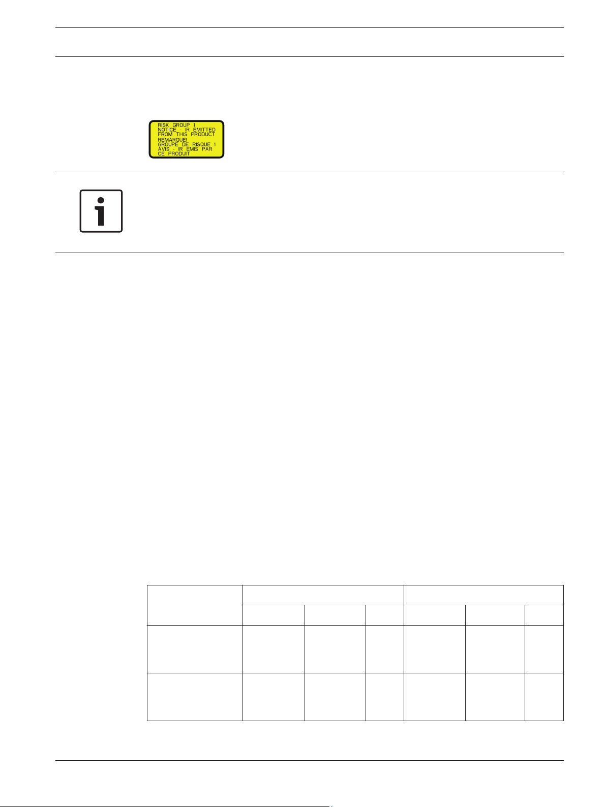
Notice!
This product has been tested according to standard IEC62471:2006 “Photobiological safety of
lamps and lamp systems”. The product emissions exceed the EXEMPT Group limit for both
Retinal Blue Light and Cornea/Lens infrared hazard as defined by IEC 62471:2006. The
product was found to meet the Risk Group 1 exposure limits for IR and White LEDs.
The IEC 62471 provides the methods to determine the risk group of any lamp or any product
incorporating a lamp. The risk groups in IEC 62471 indicate the degree of risk from potential
optical radiation hazards. The risk groups were developed based upon decades of lamp use
experience and the analysis of accidental injuries related to optical radiation emission.
EXEMPT Group – no optical hazard is considered reasonably foreseeable, even for
continuous, unrestricted use. Typical examples are most frosted incandescent lamps and
fluorescent lamps used in domestic applications.
Risk Group 1 – products are safe for most use applications, except for very prolonged
exposures where direct ocular exposures may be expected. An example of Risk Group 1 is a
domestic battery operated torch (flashlight).
Exposure Hazard Value (EHV) is a ratio of the Exposure Level (distance, exposure time) to
Exposure Limit Value (ELV). When EHV is greater than 1, the device has exceeded the
Exposure Limit Values for a particular Risk Group. The ELV is the level where optical radiation
to the eye or skin is not expected to result in adverse biological effects.
The Hazard Distance (HD) is the distance from the source at which the Exposure Level equals
the appropriate ELV. In other words, when EHV=1 for a particular Risk Group.
Regarding the Cornea / Lens infrared hazard of this product, the Exposure Hazard Value (EHV)
at a test distance of 200mm is 2.19 based on EXEMPT Group exposure limits. The EHV based
on Risk Group 1 limits is 0.386. The HD for the Exempt Group is 297 mm.
Regarding the Retinal Blue Light hazard, the EHV is 22.9 based on the EXEMPT Group
exposure limits and a test distance of 200 mm. The EHV based on Risk Group 1 limits is 0.266.
The HD for the Exempt Group is 2675 mm.
These values have been summarized in the table below:
EXEMPT Group Limits Risk Group 1 Limits
Hazard
Cornea / Lens
Infrared Hazard
t, duration d, distance EHV t, duration d, distance EHV
1000 s
Hazard
200 mm
279 mm
2.19 100 s 200 mm 0.386
Distance
Retinal Blue Light
Hazard
10,000 s
Hazard
200 mm
2675 mm
22.9 100s 200 mm 0.266
Distance
Bosch Security Systems, Inc. Operation Manual 2014.05 | 1.0 | F.01U.291.520
Page 12

12 en | Safety
MIC IP starlight 7000 HD, MIC IP
dynamic 7000 HD
1.7
Customer Support and Service
If this unit needs service, contact the nearest Bosch Security Systems Service Center for
authorization to return and shipping instructions.
Service Centers
USA
Telephone: 800-366-2283 or 585-340-4162
Fax: 800-366-1329
Email: cctv.repair@us.bosch.com
Customer Service
Telephone: 888-289-0096
Fax: 585-223-9180
Email: security.sales@us.bosch.com
Technical Support
Telephone: 800-326-1450
Fax: 585-223-3508 or 717-735-6560
Email: technical.support@us.bosch.com
Repair Center
Telephone: 585-421-4220
Fax: 585-223-9180 or 717-735-6561
Email: security.repair@us.bosch.com
Canada
Telephone: 514-738-2434
Fax: 514-738-8480
Europe, Middle East & Africa Region
Please contact your local distributor or Bosch sales office. Use this link:
http://www.boschsecurity.com/startpage/html/europe.htm
Asia Pacific Region
Please contact your local distributor or Bosch sales office. Use this link:
http://www.boschsecurity.com/startpage/html/asia_pacific.htm
More Information
For more information please contact the nearest Bosch Security Systems location or visit
www.boschsecurity.com
2014.05 | 1.0 | F.01U.291.520 Operation Manual Bosch Security Systems, Inc.
Page 13
!
MIC IP starlight 7000 HD, MIC IP
dynamic 7000 HD
Unpacking | en 13
2
2.1
One (1) MIC71xx or MIC72xx Camera
Unpacking
– This equipment should be unpacked and handled with care. Check the exterior of the
packaging for visible damage. If an item appears to have been damaged in shipment,
notify the shipper immediately.
– Verify that all the parts listed in the Parts List below are included. If any items are
missing, notify your Bosch Security Systems Sales or Customer Service Representative.
– Do not use this product if any component appears to be damaged. Please contact Bosch
Security Systems in the event of damaged goods.
– The original packing carton is the safest container in which to transport the unit and must
be used if returning the unit for service. Save it for possible future use.
MIC7000 packaging is designed:
– to allow installers to configure the camera inside the shipping box.
– to provide a temporary table-top or desk-top stand.
Caution!
Take extra care lifting or moving MIC7000 cameras because of their weight (6.7 kg (14.7 lb)).
Parts List - Camera
One (1) Quick Installation Guide
One (1) Document DVD
One (1) spanner tool [to remove and to attach the yoke caps in order to cant the camera if desired,
and to remove the access plug from the camera head when installing the optional illuminator
accessory (sold separately)]
One (1) base gasket
One (1) RJ45 coupler
Four (4) MAC address labels
One (1) ground screw
2.2
1 Phillips-head screwdriver to secure the ground lug of the camera
1 Adjustable wrench or socket set to secure the base of the camera to mounting accessories
1 Torque wrench with 1/4 in. drive to use the spanner tool (supplied) for removing yoke caps and
blanking plugs if necessary
Additional Tools
The following table lists additional tools (not supplied by Bosch) that may be required to
install a MIC camera or its accessories:
1 Torx driver, T27, to remove Torx bolts from yoke arms if canting the camera (optional)
Bosch Security Systems, Inc. Operation Manual 2014.05 | 1.0 | F.01U.291.520
Page 14

14 en | Product Description
MIC IP starlight 7000 HD, MIC IP
dynamic 7000 HD
3
Accessories
MIC-DCA-H
- MIC-DCA-HB
- MIC-DCA-HW
- MIC-DCA-HG
Product Description
The MIC7000 camera is a high-performance, weatherproof, ruggedized, fully functional day/
night PTZ camera that has been designed to offer a reliable, robust, and high-quality
surveillance solution for extreme security applications.
Image control and quality are integral aspects of any PTZ camera, and the MIC7000 camera
delivers outstanding clarity and image detail. The camera has a professional-grade imaging
platform capable of delivering 720p50/60 or 1080p25/30 HD resolution in environments with
ambient light extremes.
Both camera variants--MIC IP starlight 7000 HD (MIC71xx) and MIC IP dynamic 7000 HD
(MIC72xx)--have a 30x optical zoom (12x digital) and flexible, field-selectable mounting
orientations (upright, inverted, or canted) to achieve the perfect field of view.
A long-life silicone wiper blade mounted on a spring-loaded arm is standard on all MIC
cameras.
The following table identifies the optional accessories for MIC cameras. Refer to the
datasheets of each accessory for details. Some accessories may not be available in all regions.
Description Accessories Description
Hinged Deep Conduit Adapter in
Black
White
Grey
MIC-SCA
- MIC-SCA-BD
- MIC-SCA-WD
- MIC-SCA-GD
Shallow Conduit Adapter in
Black
White
Grey
MIC-CMB
- MIC-CMB-BD
- MIC-CMB-WD
- MIC-CMB-GD
MIC-WMB
- MIC-WMB-BD
- MIC-WMB-WD
- MIC-WMB-GD
MIC-PMB Pole Mount Bracket (stainless
NPD-PSU-HPOE VIDEOJET connect (Full-featured
VG4-A-PSU1
VG4-A-PSU2
MIC-ALM-WAS-24 Alarm and washer interface
Corner Mount Bracket in
Black
White
Grey
Wall Mount Bracket in
Black
White
Grey
steel only)
network interface unit/power
supply)
24 VAC (96 W) power supply NPD-9501A 95 W midspan
accessory unit
MIC-SPR
- MIC-SPR-BD
- MIC-SPR-WD
- MIC-SPR-GD
MIC-ILx-100
- MIC-ILB-100
- MIC-ILW-100
- MIC-ILG-100
MICIP67-5PK IP67 Weatherization/Connector Kit
NPD-6001A 60 W midspan [Not for use with
MIC-67SUNSHLD Sunshield (white only)
Spreader Plate in
Black
White
Grey
User-installable illuminator accessory
designed specifically for MIC7000
cameras (except the extreme low
temperature models) , in
Black
White
Grey
extreme low temperature models or
with the illuminator accessory.]
2014.05 | 1.0 | F.01U.291.520 Operation Manual Bosch Security Systems, Inc.
Page 15
Determine system
configuration.
Operate the camera.
(Refer to Section 16.)
Connect network cable
(Refer to Section 10.)
Install
illuminator.
Install
sunshield.
Configure settings.
(Refer to Section 13.)
Alarm/Washer
Interface Unit
VIDEOJET connect
PSU
Cant the camera.
(Refer to Section 11.)
Install cabling between power
source and camera mounting site.
Install MIC Camera.
(Refer to Section 9.)
Power supply source
or PoE device
Connect and configure
camera in box or
on table-top stand.
(Refer to Sections 5 & 6.)
Install optional accessories.
(Refer to individual installation manuals.)
Select mounting
location and
orientation.
(Refer to Section 7.)
Install mounting
accessories and
conduit (if applicable).
Identify required
mounting accessories.
(Refer to Section 8.)
Identify Mounting Site Requirements.
Install a
sunshield?
YES
YES
NO
NO
Will
camera
be canted?
Pre-
configure
camera?
NO
YES
YES
NO
Install
optional
camera
access-
ories?
MIC IP starlight 7000 HD, MIC IP
dynamic 7000 HD
Overview of Installation Steps | en 15
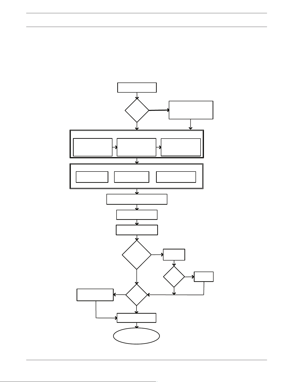
4
Overview of Installation Steps
The following figure identifies the steps to install a MIC7000 camera.
To install your MIC camera, follow these steps in sequence.
Note: Depending on your model of camera, your desired mounting location and orientation, as
well as your mounting brackets and chosen camera accessories, you may not need to
complete every step.
Bosch Security Systems, Inc. Operation Manual 2014.05 | 1.0 | F.01U.291.520
Page 16
!
16 en | Configuration Programming in the Shipping Box
MIC IP starlight 7000 HD, MIC IP
dynamic 7000 HD
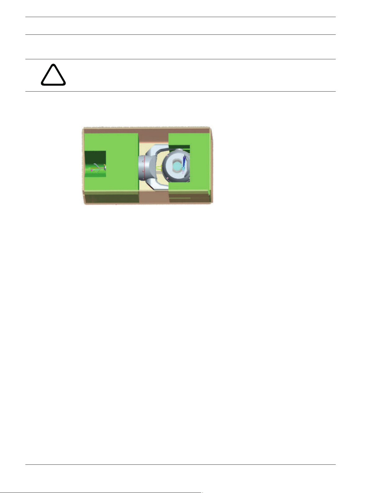
5
Configuration Programming in the Shipping Box
Caution!
Take extra care lifting or moving MIC7000 cameras because of their weight (6.7 kg (14.7 lb)).
The camera packaging allows installers to connect the camera to the network and configure
the camera still in the box.
1. Remove the accessories box from the top, middle section of the box.
2. Supply power to the camera and Connect the Camera to the Network, page 28. Note that
the wiper moves one time across the camera window, and then returns to parked position.
3. Configure the camera. Refer to Configuration, page 37 for details.
Note: Do not change the camera orientation to “Inverted” while the camera is still in the box.
The camera head must be free to rotate. If you must change the camera’s orientation to
“Inverted,” remove the camera from the box and configure it by following the steps in
Configuration Programming on a Temporary Table-top Stand, page 17.
4. Disconnect the wires/cables from the connectors in the base of the camera.
2014.05 | 1.0 | F.01U.291.520 Operation Manual Bosch Security Systems, Inc.
Page 17
MIC IP starlight 7000 HD, MIC IP
dynamic 7000 HD
Configuration Programming on a Temporary Table-top Stand | en 17
6
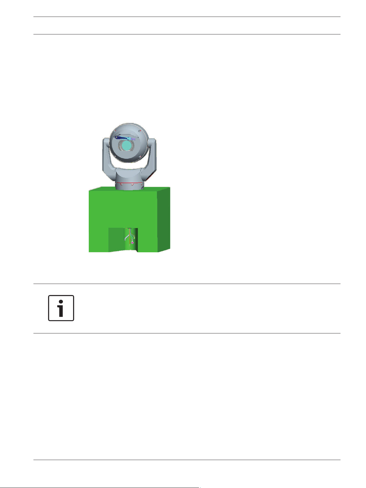
Configuration Programming on a Temporary Table-top Stand
The camera (still in the foam) can stand temporarily on a flat, horizontal surface such as a
desk or a table during initial network connection and configuration.
1. Remove the accessories box from the top, middle section of the box.
2. Remove the camera, still in the foam, from the box. Place the camera upright on a flat,
horizontal surface.
3. Remove the foam covering the head of the camera.
4. Supply power to the camera and Connect the Camera to the Network, page 28. Note that
the wiper moves one time across the camera window, and then returns to parked position.
5. Configure the camera. Refer to Configuration, page 37 for details.
Notice!
If you change the camera orientation to “Inverted” (from the Settings page of the web
browser: Advanced > Camera > Installer Menu > Orientation), then the camera head will
rotate automatically into inverted position (180°). Note that the visor will be near the top of
the body of the camera.
6. Disconnect the wires/cables from the connectors in the base of the camera.
Bosch Security Systems, Inc. Operation Manual 2014.05 | 1.0 | F.01U.291.520
Page 18
!
18 en | Mounting Location and Mounting Orientation
MIC IP starlight 7000 HD, MIC IP
dynamic 7000 HD
7
7.1
Mounting Location and Mounting Orientation
Select the Mounting Location
MIC cameras are designed for easy installation in various locations such as directly onto
buildings and poles suitable to support CCTV equipment.
Select a secure installation location and mounting position for the device. Ideally, this is a
location where the device cannot be interfered with either intentionally or accidentally.
Ensure that the location has the appropriate clearance from power and lightning conductors,
in accordance with NEC725 and NEC800 (CEC Rule 16-224 and CEC Section 60).
Do not install the device near:
– Any heat sources
– Any overhead power lines, power circuits, or electrical lights, or where the device may
contact power lines, circuits, or lights
4 Ensure that the selected mounting surface is capable of supporting the combined weight
of the camera and mounting hardware (sold separately) under all expected conditions of
load, vibration, and temperature.
Notice!
MIC cameras must be secured to one of the following surfaces:
- Concrete (Solid/Cast)
- Concrete Masonry Unit (Concrete Block)
- Brick (all types)
- Metal (Steel/Aluminum, minimum 1/8-in. thick)
Caution!
Risk of lightning strikes
If the camera is installed in a highly exposed location where lightning strikes may occur, then
Bosch recommends installing a separate lightning conductor within 0.5 m (1.6 ft) of the
camera and at least 1.5 m (4.9 ft) higher than the camera. A good earth bonding connection
to the camera housing itself will provide protection against damage from secondary strikes.
The camera housing itself is constructed to cope with secondary strikes. If the correct
lightning protection is applied, then no damage to the internal electronics or camera should
result.
Installation in a damp environment (for example, near a coastline)
The fasteners and fixtures shipped with the camera help to keep the camera secure. Always
use Bosch-supplied screws and other fasteners when installing or performing maintenance on
the camera.
The camera head has three (3) plastic screws that are factory-installed to prevent corrosion in
units which do not have accessories installed on the camera head. If you install a sunshield or
an illuminator accessory, you will remove those screws and replace them with the screws that
ship with each accessory.
Before installation, inspect the metal parts of the camera for paint that is chipped or
otherwise damaged. If you notice any paint damage, touch up the damage with locally
available paint or sealants.
2014.05 | 1.0 | F.01U.291.520 Operation Manual Bosch Security Systems, Inc.
Page 19
MIC IP starlight 7000 HD, MIC IP
dynamic 7000 HD
Avoid installation practices that may bring the camera’s metal mountings in contact with
materials such as stainless steel. Such contacts can result in galvanic corrosion and degrade
the cosmetic appearance of the camera. These cosmetic damages caused by improper
installation are not covered by warranty as they do not affect the functionality of the camera.
Mounting Location and Mounting Orientation | en 19
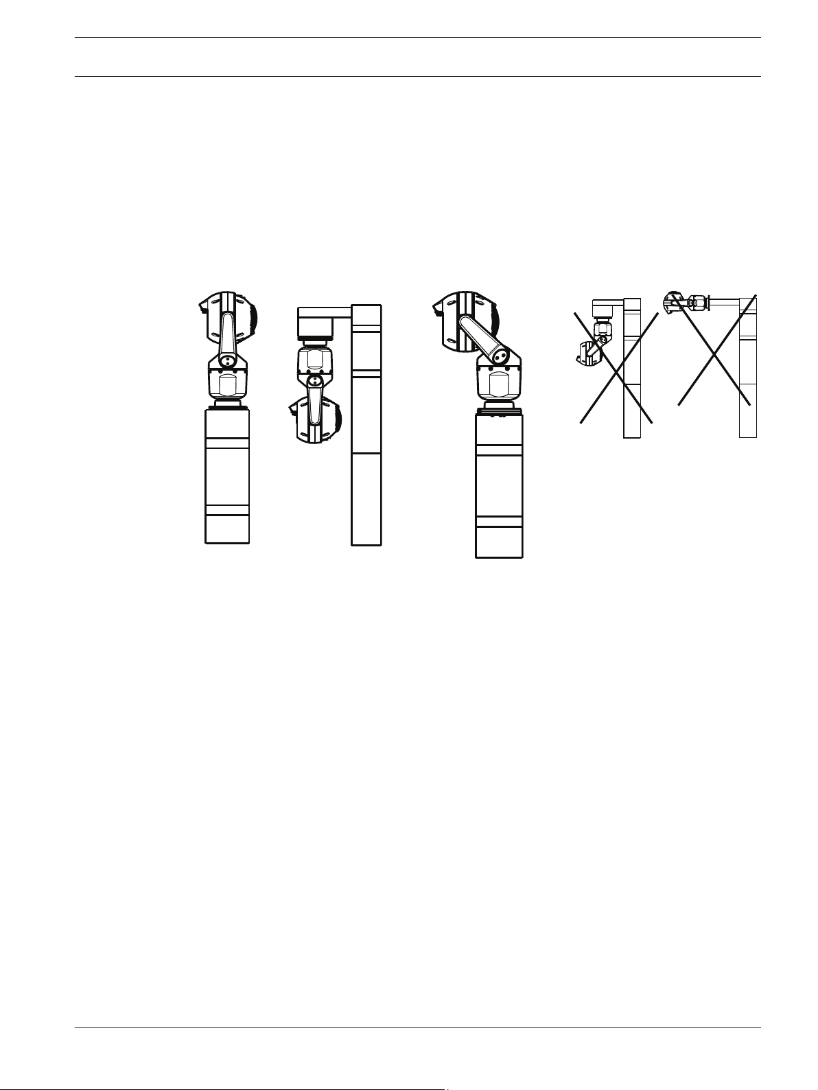
7.2
Select the Mounting Orientation
MIC Series cameras are designed to be mounted upright (straight up, 90°), inverted (straight
down, 90°), or canted upright (ball up, 45°). The tilt limits for the canted unit prevent it from
working properly if mounted ball down. See the figures below for illustrations of the correct
and the incorrect mounting orientations of MIC cameras.
Correct mounting orientation -
upright, inverted
Correct mounting orientation -
canted
Incorrect mounting orientation
Note the position of the visor when the camera is installed in inverted orientation. The visor is
close to the top of the pan shaft (the body of the MIC), instead of at the bottom of the
inverted camera.
Note: For canted cameras, ensure that your mounting location provides the necessary
clearance (370 mm (14.6 in.)) for the camera head to pan.
Bosch Security Systems, Inc. Operation Manual 2014.05 | 1.0 | F.01U.291.520
Page 20
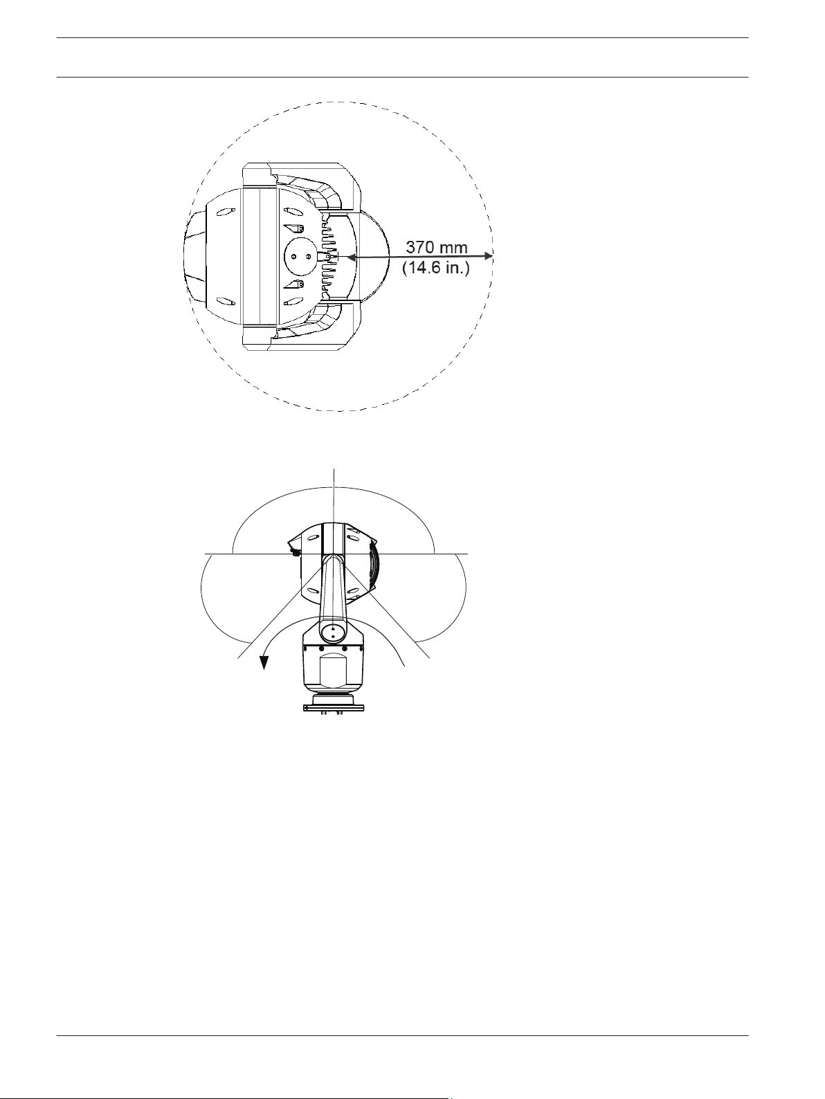
55° 55°
90° 90°
AutoPivot
en | Mounting Location and Mounting Orientation
20
Figure 7.1: Top view of canted MIC7000 illustrating distance of pan clearance
The figure below illustrates the tilt range of the camera in upright orientation.
MIC IP starlight 7000 HD, MIC IP
dynamic 7000 HD
Figure 7.2: MIC7000 Tilt Range: 145° each direction; 290° if AutoPivot enabled
2014.05 | 1.0 | F.01U.291.520 Operation Manual Bosch Security Systems, Inc.
Page 21
MIC IP starlight 7000 HD, MIC IP
dynamic 7000 HD
Overview of Mounting Options | en 21
8
Overview of Mounting Options
Bosch sells a complete series of mounting brackets that support multiple mounting
configurations.
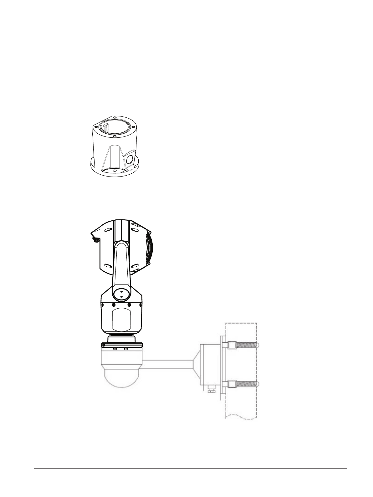
The most common type of mounting location is the top of a pole suitable to support CCTV
equipment and that provides a robust mounting platform to minimize camera motion and
typically has a large base cabinet for mounting ancillary equipment such as power supplies.
The hinged DCA is well-suited to installations on top of a pole.
Figure 8.1: Typical hinged DCA mount configuration
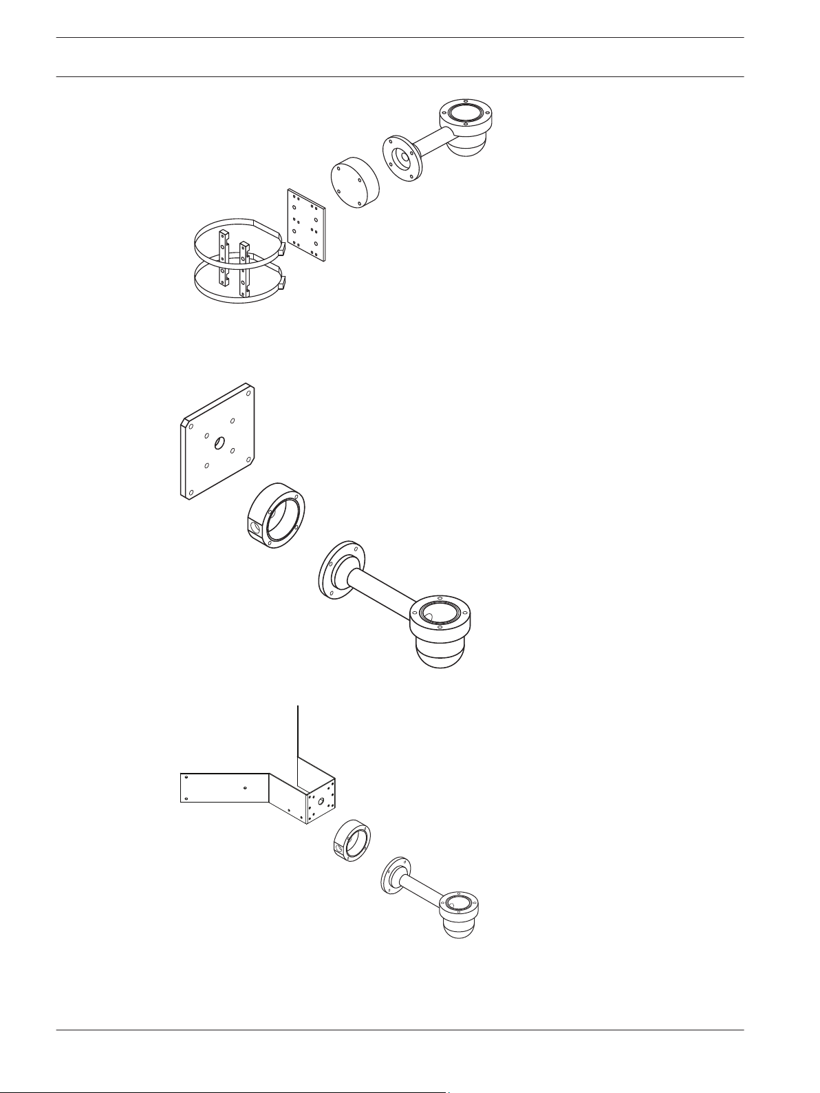
The camera can also be mounted on the side of a lamp post, pole, or similar column using the
Pole Mount Bracket (MIC-PMB). Be aware that lamp posts can often be subject to movement
and are not suitable platforms in all conditions or for all applications.
The figure below identifies the three mounting brackets (each sold separately) that are
necessary to mount the MIC camera on the side of a pole.
Note: The figure identifies the part numbers, as well as the codes for the available colors (-BD
for black, WD for white, and GD for grey) of each mounting bracket.
Bosch Security Systems, Inc. Operation Manual 2014.05 | 1.0 | F.01U.291.520
Page 22
MIC-WMB-BD,
-WD, -MG
MIC-SCA-BD,
-WD, -GD
MIC-PMB
MIC-SPR-BD,
-WD, -GD
MIC-SCA-BD,
-WD, -GD
MIC-WMB-BD,
-WD, -MG
MIC-CMB-BD,
-WD, -MG
MIC-SCA-BD,
-WD, -GD
MIC-WMB-BD,
-WD, -MG
en | Overview of Mounting Options
22
Figure 8.2: Typical Pole mount configuration
Other locations for mounting the camera include the top of a building, the side (wall) of a
building, the corner of a building, and under the eave of a building.
MIC IP starlight 7000 HD, MIC IP
dynamic 7000 HD
Figure 8.3: Typical Wall mount configuration
Figure 8.4: Typical Corner mount configuration
2014.05 | 1.0 | F.01U.291.520 Operation Manual Bosch Security Systems, Inc.
Page 23
MIC IP starlight 7000 HD, MIC IP
dynamic 7000 HD
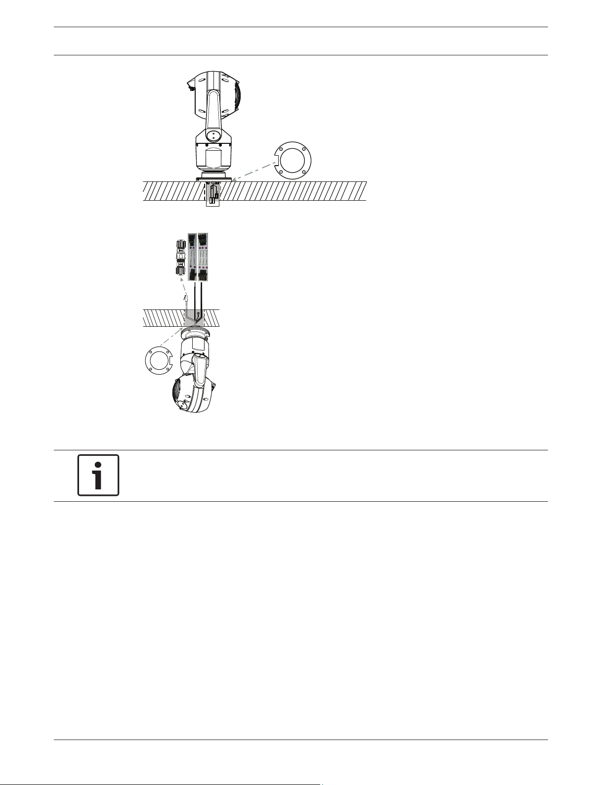
Figure 8.5: Direct surface mount – camera upright (MIC + base gasket)
Overview of Mounting Options | en 23
Figure 8.6: Direct surface mount – camera inverted (MIC + base gasket + IP67 Weatherization/Connector
Kit)
Notice!
Observe all appropriate safety precautions and local building regulations.
Refer to the MIC Series Mounting Brackets Installation Guide for installation instructions.
Bosch Security Systems, Inc. Operation Manual 2014.05 | 1.0 | F.01U.291.520
Page 24
!
!
24 en | Install the Camera
MIC IP starlight 7000 HD, MIC IP
dynamic 7000 HD
9
Install the Camera
Caution!
Installation must be made by qualified personnel and conform to ANSI/NFPA 70 (the National
Electrical Code® (NEC)), Canadian Electrical Code, Part I (also called CE Code or CSA C22.1),
and all applicable local codes. Bosch Security Systems, Inc. accepts no liability for any
damages or losses caused by incorrect or improper installation.
Caution!
ELECTRIC SHOCK HAZARD
To reduce the risk of electric shock, disconnect power to the camera and/or to the power
supply unit before moving the camera, before installing any accessories, and before mounting
the camera.
You can install the camera:
– onto a MIC-DCA or a MIC wall mount
or
– directly to a mounting surface (using the optional IP67 Weatherization/Connector Kit
(MICIP67-5pk, sold separately).
Refer to the manual provided with the mount or with the kit for installation instructions.
Notice!
To maintain the NEMA 6P rating when the camera is mounted to a MIC-DCA, installers must
ensure that the user-supplied cable glands or conduit connections have NEMA 6P ratings.
2014.05 | 1.0 | F.01U.291.520 Operation Manual Bosch Security Systems, Inc.
Page 25
!
MIC IP starlight 7000 HD, MIC IP
dynamic 7000 HD
Make Connections - Power and Control | en 25
10
10.1
10.2
Make Connections - Power and Control
About Camera Power and Control
The camera transmits PTZ control commands and images over a TCP/IP network. It also allows
users to configure the camera display settings, camera operating settings, and to configure
the network parameters.
The camera incorporates a network video server in the IP module. The primary function of the
server is to encode video and control data for transmission over a TCP/IP network. With its H.
264 encoding, it is ideally suited for IP communication and for remote access to digital video
recorders and multiplexers. The use of existing networks means that integration with CCTV
systems or local networks can be achieved quickly and easily. Video images from a single
camera can be simultaneously received on several receivers.
Power Source Options
The camera can be powered by a network compliant to High Power-over-Ethernet (Bosch’s
version of High PoE) using a Bosch model of High PoE Midspans (sold separately). With this
configuration, only a single (Cat5e/Cat6) cable connection is required to view, to power, and
to control the camera.
The camera can also accept a standard 24 VAC power source if a High PoE network interface
will not be used. User-supplied wiring must be in compliance with electrical codes (Class 2
power levels).
For maximum reliability, the camera can be connected simultaneously to a High PoE Midspan
and a separate 24 VAC power source. If High PoE and 24 VAC are applied simultaneously, the
camera usually selects auxiliary input (24 VAC) and will draw minimal power from the High
PoE Midspan. If the 24 VAC power source fails, the camera switches power input seamlessly
to High PoE. After the 24 VAC power source is restored, the camera switches power input
again to 24 VAC.
If connected to both power sources, the camera will operate at 24 VAC if High PoE is not
available.
Warning!
Bosch’s version of High PoE, or PoE+:
If supplying power to the camera by PoE or a midspan device, you must install additional
surge protection.
CAMERA MODELS 60 W midspan 95 W midspan VIDEOJET connect 24 VAC PSU
Standard models with
Standard models
without illuminator
Extreme low
temperature models
Bosch Security Systems, Inc. Operation Manual 2014.05 | 1.0 | F.01U.291.520
In the table below, an "X" identifies the power source options for MIC7000 camera models.
X X X
illuminator
X X X X
X X X
Note: The MIC7000 illuminator accessory is not compatible with the extreme low temperature
models (including MIC-7130-PB4PB, MIC-7130-PW4PB, MIC-7230-PB4PB, and MIC-7230PW4PB).
Page 26
!
!
26 en | Make Connections - Power and Control
The table below identifies the power devices that can be connected simultaneously to the
camera.
If power is supplied from: Camera can receive power simultaneously from:
60 W midspan (NPD-6001A)
95 W midspan (NPD-9501A)
VIDEOJET connect (NPD-PSU-HPOE)
Caution!
Compliance with EN50130-4 Alarm Standard – CCTV for Security Applications
To meet the requirements of the EN50130-4 Alarm Standard, an ancillary uninterruptable
power (UPS) supply is necessary. The UPS must have a Transfer Time between 2–6 ms and a
Backup Runtime of greater than 5 seconds for the power level as specified on the product
datasheet.
MIC IP starlight 7000 HD, MIC IP
dynamic 7000 HD
24 VAC PSU
(VG4-A-PSU1,
VG4-A-PSU2)
10.3
Cable Type Cat5e/Cat6 Ethernet (directly to the camera, or to a network switch
Maximum Distance 100 m (330 ft)
Bandwidth 100 Base-TX
High PoE (required for models with
illuminators)
PoE+ (only for models without
illuminators)
Terminal Connector RJ45, Male
Ethernet Connections
Caution!
Ethernet cables must be routed through earth-grounded conduit capable of withstanding the
outdoor environment.
Note: Consult the National Electrical Code (NEC) for cable bundling requirements and
limitations.
between the camera and the network)
Use the 95 W midspan sold by Bosch.
Use the 60 W midspan sold by Bosch, or a midspan that is compliant to the
IEEE 802.3at, class 4 standard.
2014.05 | 1.0 | F.01U.291.520 Operation Manual Bosch Security Systems, Inc.
Page 27
MIC IP starlight 7000 HD, MIC IP
dynamic 7000 HD
Make Connections - Power and Control | en 27
10.4
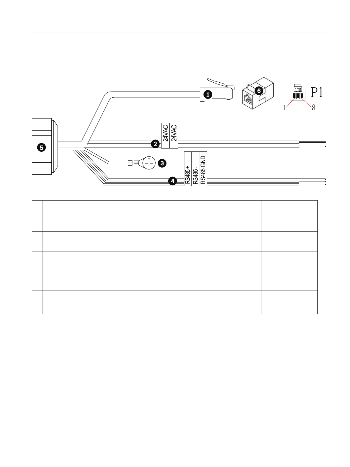
Camera Connections
All electrical and data connections from the camera are made from the connectors in the base
of the camera.
Figure 10.1: MIC7000 connectors
Description Wire Color
1 RJ45 (Cat5e/Cat6) connector (male) (supporting High PoE and PoE+) for power and
communication between a Bosch model of High PoE Midspan or an NPD-PSU-HPOE
2 24 VAC power wires (24 gage) to VG4-A-PSU1 or VG4-A-PSU2 (if not using a PoE
network)
Line (L) = Black
Neutral (N) = White
3 Chassis (Earth) ground wire (18 gage) with connector lug Green
4 RS-485 connections for communication to / from the MIC-ALM-WAS-24 + = Purple
- = Yellow
GND = Brown
5 Liquid-tight cordgrip in the base of the camera
6 RJ45 coupler (female to female)
Note: If the MIC camera will be installed directly to a mounting surface, instead of onto a MIC
DCA or a MIC wall mount bracket, Bosch recommends using the optional IP67 Weatherization/
Connector Kit (MICIP67-5pk, sold separately) to protect the connections against moisture and
dust particles. Each kit provides components for connecting up to five (5) MIC cameras. Refer
to the manual provided with the kit for installation instructions.
Bosch Security Systems, Inc. Operation Manual 2014.05 | 1.0 | F.01U.291.520
Page 28

1
2
3
4
1
2
2
A
4
B
28 en | Make Connections - Power and Control
MIC IP starlight 7000 HD, MIC IP
dynamic 7000 HD
10.5
Connect the Camera to the Network
Note: Refer to the following figure for an illustration of both options.
Option A:
1. Connect an Ethernet cable (Cat5e/Cat6) from the RJ45 connector of the camera to a
network switch attached to the Local Area Network (LAN).
2. Connect the dedicated network switch to the RJ45 connector on the computer.
3. Connect the 24 VAC wires to the power source.
4. Connect the RS-485 wires to the MIC-ALM-WAS-24 (optional).
5. Attach the green ground wire (item 3 in the figure above) from the camera to an earthground connection on the mounting surface using the supplied screw or a suitable usersupplied fastener.
Option B:
1. Connect an Ethernet crossover cable from the RJ45 connector of the camera directly to a
networking device such as a computer, a DVR/NVR, etc.
2. Attach the green ground wire (item 3 in the figure above) from the camera to an earthground connection on the mounting surface using the supplied screw or a suitable usersupplied fastener.
Figure 10.2: MIC7000 IP System Configuration
MIC7000 camera
1
2 IP connection
3 Network switch
4 Networking device (computer, DVR/NVR, etc.)
2014.05 | 1.0 | F.01U.291.520 Operation Manual Bosch Security Systems, Inc.
Page 29
!
!
MIC IP starlight 7000 HD, MIC IP
dynamic 7000 HD
Cant the Camera | en 29
11
Cant the Camera
Note:
For simplicity, the graphics in this section are only of the camera (and the specific accessory
that you are installing, if applicable). The graphics do not depict other accessories that you
may have installed already.
MIC7000 cameras feature on-site canting functionality.
Installers can adjust the camera from an upright position to a canted position if desired. This
allows the camera to be installed at a 45º angle so that its field of view (FOV) can observe the
scene directly beneath the camera.
Note: Canting is not applicable when the camera is installed in inverted orientation.
Warning!
Risk of bodily injury.
Unplug the device from its power source before canting the device. Ensure that the head is
supported so that it doesn't tilt downward unexpectedly after the Torx screws are removed
from the yoke arms and pinch fingers or other body parts.
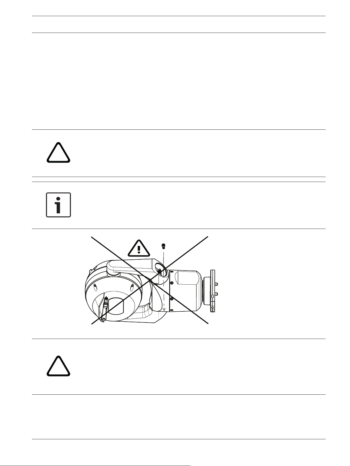
Notice!
Risk of damage to the camera
Do not, under any circumstances, cant the camera while the camera is on its side. Cant the
camera from an upright position only, in order to prevent screws or other objects from falling
into the open spaces in the arms when the yoke caps are removed.
Figure 11.1: Do NOT allow screws or other objects to fall inside camera!
Warning!
Risk of bodily injury.
Do not stand the canted (45°) MIC camera upright on the camera base or on an unsecured
DCA, with the DCA base upright! It is unstable and might fall and cause bodily injury and/or
damage to the camera. Bosch strongly recommends canting the camera after attaching it to a
DCA and mounting it in the desired location.
Bosch Security Systems, Inc. Operation Manual 2014.05 | 1.0 | F.01U.291.520
Page 30
1/4”
30 en | Cant the Camera
MIC IP starlight 7000 HD, MIC IP
dynamic 7000 HD
Notice!
If your MIC camera will be canted, install the sunshield first.
If your MIC camera will have both illuminator and sunshield accessories, install the illuminator
first.
Extreme low temperature models do not support a sunshield.
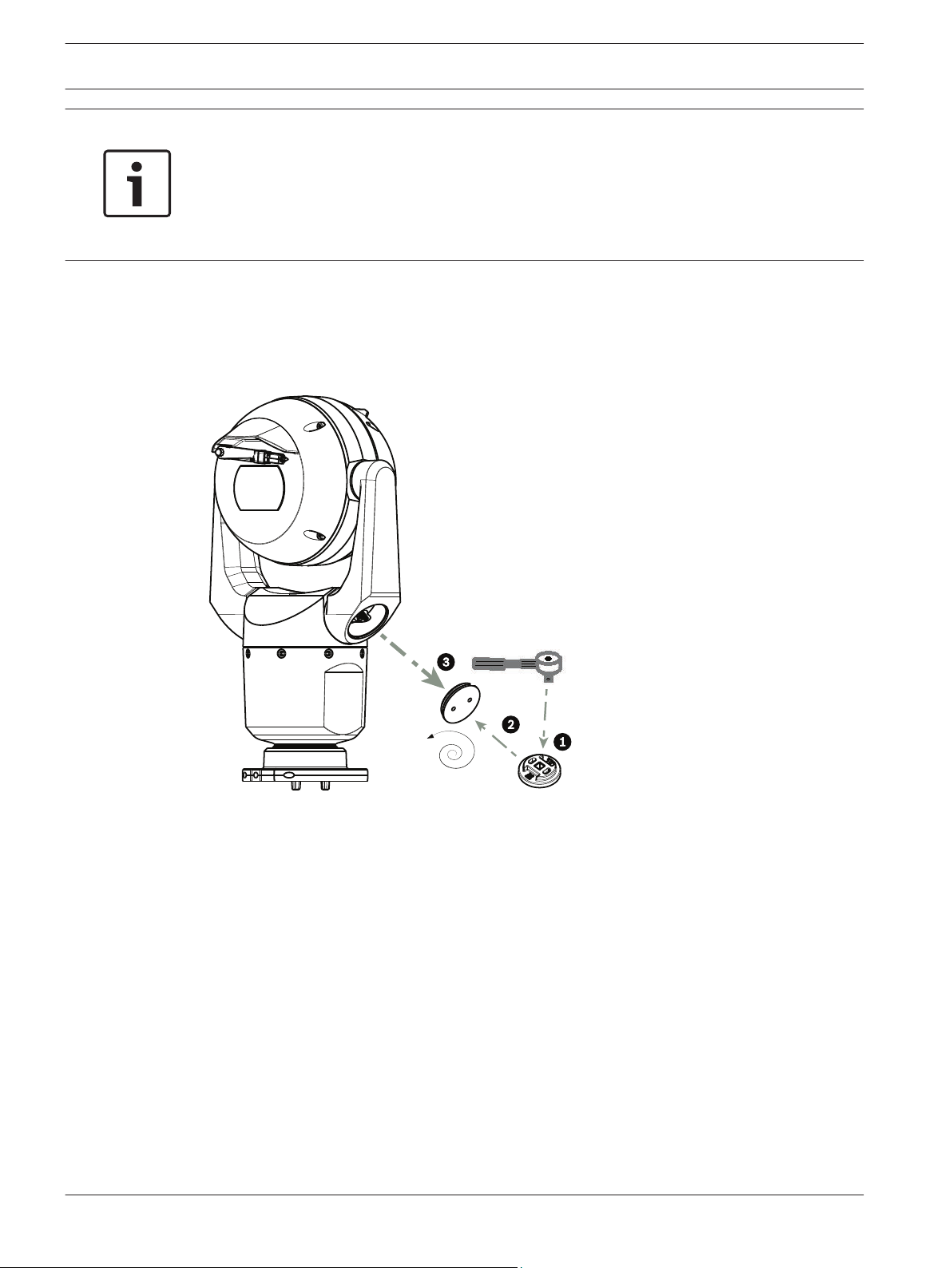
To cant the camera, follow these steps:
1. Remove the yoke cap (item 3 in the figure below) on one yoke arm of the camera, using a
Torque wrench with ¼ in. drive (item 1, not supplied) with the spanner tool (item 2,
supplied).
Repeat for the second arm.
Figure 11.2: Remove yoke caps with spanner tool
2. Remove the two (2) T27 Torx screws at the bottom of one yoke arm using a T27 Torx
wrench (not supplied).
2014.05 | 1.0 | F.01U.291.520 Operation Manual Bosch Security Systems, Inc.
Page 31

T27 Torx
MIC IP starlight 7000 HD, MIC IP
dynamic 7000 HD
Cant the Camera | en 31
Figure 11.3: Remove screws from yoke arms
Notice!
Risk of damage to the device.
Carefully support the head of the camera while completing the next three (3) steps.
3. Repeat step above for the second arm.
4. Carefully rotate the arms and head assembly forward.
Notice!
Risk of damage to the device.
Do not cant the camera, or let it fall, in the wrong direction! The camera should cant only in
the direction indicated in the figure directly below.
Bosch Security Systems, Inc. Operation Manual 2014.05 | 1.0 | F.01U.291.520
Page 32

4.3 N m
(≈ 38 in. lb)
T27 Torx
32 en | Cant the Camera
MIC IP starlight 7000 HD, MIC IP
dynamic 7000 HD
Figure 11.4: Canting the camera head
5. Reinsert two (2) Torx screws into each yoke arm. Tighten the screws.
Figure 11.5: Tighten yoke arm screws
6. Attach the yoke caps using the Torque wrench with ¼ in. drive with the spanner tool.
2014.05 | 1.0 | F.01U.291.520 Operation Manual Bosch Security Systems, Inc.
Page 33

1.4 N m
(≈ 12 in. lb)
1/4”
MIC IP starlight 7000 HD, MIC IP
dynamic 7000 HD
Figure 11.6: Attach yoke caps
7. Canting is complete.
Cant the Camera | en 33
Bosch Security Systems, Inc. Operation Manual 2014.05 | 1.0 | F.01U.291.520
Page 34

34 en | Typical System Configurations
MIC IP starlight 7000 HD, MIC IP
dynamic 7000 HD
12
12.1
Typical System Configurations
Typical IP Configuration with 95 W midspan (no I/O connections)
Figure 12.1: Typical IP configuration with 95 W midspan (no I/O connections)
1
MIC7000 camera
2 MIC Hinged DCA (MIC-DCA-Hx)
3 High PoE (Network) cable (Cat5e/Cat6; maximum 100 m (330 ft)) (user-supplied)
between camera and 95 W midspan (NPD-9501A)
4 95 W midspan (NPD-9501A)
5 Data only IP cable (Cat5e/Cat6; maximum 100 m (330 ft)) (user-supplied) between
midspan and head-end network
2014.05 | 1.0 | F.01U.291.520 Operation Manual Bosch Security Systems, Inc.
Page 35

MIC IP starlight 7000 HD, MIC IP
dynamic 7000 HD
Typical System Configurations | en 35
12.2
Typical Configuration with MIC-ALM-WAS-24
Figure 12.2: Typical configuration with MIC-ALM-WAS-24
1 MIC7000 camera 6 24 VAC Power pack, 1A, 50/60 Hz (user-
2 MIC Hinged DCA (MIC-DCA-Hx) 7 Washer pump accessory
3 RS-485 cable, 3-conductor (user-
supplied)
4 MIC-ALM-WAS-24 enclosure 9 Alarm input / output interface cables
5 Interface cable for 24 VAC (user-
supplied) for MIC-ALM-WAS-24
supplied)
8 Interface cable for washer control (user-
supplied)
(user-supplied)
10 Monitored switch for Tamper Alarm
(user-supplied)
Bosch Security Systems, Inc. Operation Manual 2014.05 | 1.0 | F.01U.291.520
Page 36

36 en | Typical System Configurations
MIC IP starlight 7000 HD, MIC IP
dynamic 7000 HD
12.3
Figure 12.3: Typical IP configuration with NPD-PSU-HPOE
Typical IP Configuration with NPD-PSU-HPOE
1 MIC7000 camera 6 Audio input / output interface cables
(user-supplied)
2 MIC Hinged DCA (MIC-DCA-Hx) 7 Washer pump accessory
3 High PoE (Network) cable (Cat5e/Cat6;
100 m maximum) (user-supplied)
8 Washer output, 2-conductor (user-
supplied)
between camera and NPD-PSU-HPOE
4 NPD-PSU-HPOE enclosure 9 Alarm input / output interface cables
(user-supplied)
5 120 / 230 VAC 10 Data-only IP cable (Cat5e/Cat6 or fiber)
to head-end network
2014.05 | 1.0 | F.01U.291.520 Operation Manual Bosch Security Systems, Inc.
Page 37

MIC IP starlight 7000 HD, MIC IP
dynamic 7000 HD
Configuration | en 37
13
13.1
Configuration
System Requirements
The camera requires specific software and hardware to allow a user to view live images and to
configure camera settings over a TCP/IP network. These requirements are:
– A computer with the Microsoft Windows XP, Vista, or Windows 7 operating system,
network access, and the Microsoft Internet Explorer Web browser version 8.0 or later, or
– A computer with Microsoft Windows XP, Vista, or Windows 7 operating system, network
access, and reception software such as the Bosch Video Management System or the
Video Client, or other third party head-end video management software, or
– A compatible hardware decoder from Bosch Security Systems connected to a video
monitor.
Notice!
The Web browser must be configured to enable Cookies to be set from the IP address of the
unit.
In Windows 7, deactivate protected mode on the Security tab under Internet Options. You can
find notes on using Microsoft Internet Explorer in the online Help in Internet Explorer. In
Windows Vista, deactivate protected mode on the Security tab under Internet Options.
You can find notes on using Microsoft Internet Explorer in the online Help in Internet
Explorer.
If you choose to use a computer running Microsoft Internet Explorer or any of the Bosch
software, the computer must conform to the following minimum requirements:
– Operating System: Windows XP (Service Pack 3) or Windows 7 (32 or 64 bits)
– Processor: Intel Pentium Quad Core, 3.0 GHz or comparable
– RAM: 2048 MB
– Free Hard Disk Space: 10 GB
– Video system: NVIDIA GeForce 8600 or higher display with a minimum of 16-bit color
– Network interface: 100/1000-BaseT
– Software:
– Microsoft Internet Explorer, version 8.0 or higher
– Video Client
– DirectX 9.0c
– Oracle Java Virtual Machine 1.6.0_26 or newer
The camera includes the means to decode the video via a web browser; however, for more
advanced features such as local recording to PC, snapshot, and full screen display, you must
obtain MPEG-ActiveX.
For the latest versions of the Video Client, DirectX, Oracle Java Virtual Machine, and MPEGActiveX software, go to www.boschsecurity.com, navigate to the product page for your camera,
and then download the software from the Software tab.
Notice!
Ensure that the graphics card is set to 16-bit or 32-bit color. If you need further assistance,
contact your PC system administrator.
Bosch Security Systems, Inc. Operation Manual 2014.05 | 1.0 | F.01U.291.520
Page 38

38 en | Configuration
MIC IP starlight 7000 HD, MIC IP
dynamic 7000 HD
13.2
Configuring the Camera
To operate the camera in your network, you must configure the camera properly for your
network. You will need the following information:
– Unit IP address: An identifier for the camera on a TCP/IP network.
Default: 192.168.0.1 (if your network does not have a DHCP server)
or
the first available IP address (if your network has a DHCP server)
Note: You will likely need to change the IP address of your camera so that it does not
conflict with another device on your network. Refer to Basic Mode: Network, page 43 for
more information.
– Subnet mask: A mask used to determine what subnet an IP address belongs to.
Default: 255.255.255.0
– Gateway IP address: A node on a network that serves as an entrance to another network.
Default: 0.0.0.0
– Port: An endpoint to a logical connection in TCP/IP and UDP networks. The port number
identifies the use of the port for use through a firewall connection.
Notice!
Ensure that the network parameters of your camera are available before you begin
configuration. Contact your local network administrator for a valid IP address, Subnet mask,
and Gateway IP address.
The following sections provide instructions about installing the software necessary to view
images over an IP connection, configuring the IP network settings, and accessing the camera
images from a Web browser.
To change the IP address or any network settings, you can use:
– the Configuration Manager software or
– the MIC7000 Series server.
13.2.1
13.2.2
2014.05 | 1.0 | F.01U.291.520 Operation Manual Bosch Security Systems, Inc.
Using the Configuration Manager
Configuration Manager is an optional network utility provided on the Bosch Security Systems
Web site. Use the Configuration Manager Manual to make any configuration changes.
Note: Depending on the PC network security settings, the user may need to add the new IP
address to the browser’s trusted sites list for the controls to operate.
Using the MIC7000 Series Web Server
1. Set the IP address on the network device to 192.168.0.10 to ensure that the network device
and the MIC7000 camera are on the same Subnet.
2. Launch your web browser (such as Microsoft Internet Explorer) and navigate to the
following URL: http://192.168.0.1
The web browser opens the LIVE page for the MIC7000 camera; a security warning message is
displayed.
3. Check the Always Trust Box, and then click YES.
4. Click the SETTINGS link at the top of the LIVE page.
5. In the left pane of the window, click Advanced Mode, and then click Network. The Network
menu expands.
6. Click Network Access to open the Network Access page.
Page 39

MIC IP starlight 7000 HD, MIC IP
dynamic 7000 HD
Configuration | en 39
7. Configure the settings on this page based on the addresses provided by your local network
administrator. Note that the text on the Set button changes to Set and Reboot.
8. Click Set and Reboot. The camera will reset (go through the homing sequence, which
usually takes 30 seconds to complete), and then the LIVE page appears, with updated video
and the new IP address.
Bosch Security Systems, Inc. Operation Manual 2014.05 | 1.0 | F.01U.291.520
Page 40

!
!
40 en | Configuration
MIC IP starlight 7000 HD, MIC IP
dynamic 7000 HD
Notice!
Click the Help on this page? link if you need more information.
13.2.3
NOTE: Screenshots of configuration settings in this manual are from a MIC 7130 model.
Because of firmware or software updates, the screenshots may differ slightly from the
configuration settings screens in your system. Every effort has been made to ensure that the
information in this manual is accurate and current.
About the SETTINGS Page
About the SETTINGS Page
The SETTINGS page provides access to the configuration menu, which contains all the unit's
parameters arranged in groups. You can view the current settings by opening one of the
configuration screens. You can change the settings by entering new values or by selecting a
predefined value from a list field.
There are two options for configuring the unit or checking the current settings:
– Basic mode
– Advanced mode
In Basic Mode, the most important parameters are arranged in seven groups. This allows you
to change the basic settings with just a few entries and then put the device into operation.
Advanced Mode is recommended for expert users or system support personnel. You can
access all unit parameters in this mode. Settings that affect the fundamental functionality of
the unit (such as firmware updates) can only be altered in the advanced mode.
Caution!
The settings in the Advanced Mode should only be processed or modified by expert users or
system support personnel.
All settings are backed up in camera memory so they are not lost even if the power fails. The
exception is the time settings, which are lost after 1 hour without power if no central time
server is selected.
Starting Configuration
4 Click the SETTINGS link in the upper section of the window. The Web browser opens a
new page with the configuration menu.
Navigation
1. Click one of the menu items in the left window margin. The corresponding submenu is
displayed.
2. Click one of the entries in the submenu. The web browser opens the corresponding page.
Making Changes
Each configuration screen shows the current settings. You can change the settings by entering
new values or by selecting a predefined value from a list field.
Not every page has a Set button. Changes to pages without a Set button are set immediately.
If a page does show a Set button, you must click the Set button for a change to take effect.
Caution!
Save each change with the associated Set button.
Clicking the Set button saves the settings only in the current field. Changes in any other fields
are ignored.
2014.05 | 1.0 | F.01U.291.520 Operation Manual Bosch Security Systems, Inc.
Page 41

MIC IP starlight 7000 HD, MIC IP
dynamic 7000 HD
Configuration | en 41
13.3
Some changes only take effect after the unit is rebooted. In this case, the Set button changes
to Set and Reboot.
1. Make the desired changes.
2. Click the Set and Reboot button. The camera reboots and the changed settings are
activated.
Configuring Audio (Optional)
Note for MIC7000 cameras only: These options are available only if you have connected a
VIDEOJET connect device (NPD-PSU-HPOE) to your camera.
Enabling Audio Transmission
To transmit audio via the IP connection, follow these steps:
1. Open the LIVE page, and then click the Settings tab.
2. In the left pane, click Advanced, and then click Web Interface. The Web Interface menu
expands.
3. Click LIVE Functions. The LIVE Functions page appears.
4. Click the Transmit Audio radio button to enable for audio.
Activating Audio Reception
To configure audio via the Web browser, follow these steps:
1. Open the LIVE page, and then click the Settings tab.
2. In the left pane, click Advanced Mode, and then click Camera. The Camera menu
expands.
3. Click Audio. The Audio page appears. The page displays the current video image in the
small window next to the slide controls to help you verify the audio source and improve
the Peak levels.
4. Select the protocol in the Audio field to activate audio over IP. (Change the option to
ON.)
Notice!
The audio signal is sent in a separate data stream parallel to the video data, and so increases
the network load. The audio data is encoded according to G.711 or L16 and requires an
additional bandwidth of approximately 80 Kbit/s for each connection.
5. If you wish to configure the input and output gain of the audio signals, set the Line In and
Line Out fields to suit your specific requirements. Changes are effective immediately. The
current level is displayed next to the slide control to help do this. Make sure that the
display does not go beyond the green zone during modulation.
For more information, refer to Audio, page 64.
Bosch Security Systems, Inc. Operation Manual 2014.05 | 1.0 | F.01U.291.520
Page 42

!
42 en | Configuration via IP, Basic Mode
MIC IP starlight 7000 HD, MIC IP
dynamic 7000 HD
14
14.1
Configuration via IP, Basic Mode
Basic Mode: Device Access
Camera name
You can give the camera a name to make it easier to identify. The name makes the task of
administering multiple units in larger video monitoring systems easier, for example using the
Bosch Video Management Systems programs.
The device name is used for the remote identification of a unit, in the event of an alarm for
example. For this reason, enter a name that makes it as easy as possible to quickly identify the
location.
Caution!
Do not use any special characters, for example &, in the name.
Special characters are not supported by the system's internal recording management and may
therefore result in the Player or Archive Player being unable to play back the recording.
Password
The camera is generally protected by a password to prevent unauthorized access to the unit.
You can use different authorization levels to limit access.
The camera operates with three authorization levels: service, user and live.
The highest authorization level is service. After entering the correct password, you can access
all the functions of the camera and change all configuration settings.
With the user authorization level, you can operate the unit and also control cameras, for
example, but you cannot change the configuration.
The lowest authorization level is live. It can only be used to view the live video image and
switch between the different live image displays.
You can define and change a password for each authorization level if you are logged in as
service or if the unit is not password protected.
Enter the password for the appropriate authorization level here.
Note: Proper password protection is only guaranteed when all higher authorization levels are
also protected with a password. If a live password is assigned, for example, a service and a
user password must also be set. When assigning passwords, you should therefore always start
from the highest authorization level, service, and use different passwords.
Confirm password
In each case, enter the new password a second time to eliminate typing mistakes.
Notice!
A new password is only saved when you click the Set button. You should therefore click the
Set button immediately after entering and confirming a password.
14.2
2014.05 | 1.0 | F.01U.291.520 Operation Manual Bosch Security Systems, Inc.
Basic Mode: Date/Time
Device date/Device time/Device time zone
If there are multiple devices operating in your system or network, it is important to
synchronize their internal clocks. For example, it is only possible to identify and correctly
evaluate simultaneous recordings when all units are operating on the same time. If necessary,
you can synchronize the unit with your computer's system settings.
Page 43

MIC IP starlight 7000 HD, MIC IP
dynamic 7000 HD
Notice!
Ensure that recording is stopped before synching to the PC.
Configuration via IP, Basic Mode | en 43
14.3
4 Click the Sync to PC button to copy your computer's system time to the camera.
Time server IP address
The camera can receive the time signal from a time server using various time server protocols,
and then use it to set the internal clock. The unit polls the time signal automatically once every
minute.
4 Enter the IP address of a time server here.
Time server type
Select the protocol that is supported by the selected time server. Preferably, you should
select the SNTP server as the protocol. This supports a high level of accuracy and is required
for special applications and subsequent function extensions.
Select Time server for a time server that works with the protocol RFC 868.
Basic Mode: Network
The settings on this page are used to integrate the camera into an existing network.
Some changes only take effect after the unit is rebooted. In this case, the Set button changes
to Set and Reboot.
1. Make the desired changes.
2. Click the Set and Reboot button. The camera reboots and the changed settings are
activated.
Note: If you change the IP address, subnet mask or gateway address, the camera is only
available under the new addresses after the reboot.
DHCP
If a DHCP server is employed in the network for the dynamic assignment of IP addresses, you
can activate acceptance of IP addresses automatically assigned to the camera. Certain
applications (VIDOS, Bosch Video Management Systems, Archive Player, Configuration
Manager) use the IP address for the unique assignment of the unit. If you use these
applications, the DHCP server must support the fixed assignment between IP address and
MAC address, and must be appropriately set up so that, once an IP address is assigned, it is
retained each time the system is rebooted.
IP address
Enter the desired IP address for camera in this field. The IP address must be valid for the
network.
Subnet mask
Enter the appropriate subnet mask for the selected IP address here.
Gateway address
If you want the unit to establish a connection to a remote location in a different subnet, enter
the IP address of the gateway here. Otherwise leave the box as 0.0.0.0.
14.4
Bosch Security Systems, Inc. Operation Manual 2014.05 | 1.0 | F.01U.291.520
Basic Mode: Encoder
Non-recording profile
You can select a profile for encoding the video signal.
You can use this to adapt the video data transmission to the operating environment (for
example, network structure, bandwidth, data load).
Page 44

44 en | Configuration via IP, Basic Mode
Pre-programmed profiles are available, each giving priority to different perspectives. When
selecting a profile, details are displayed in the list field.
Default Profile name Description
HD Image Optimized For an HD image, the video bit rate and frame quality are
HD Balanced For an HD image, the video bit rate and frame quality are
HD Bit Rate Optimized For an HD image, the video bit rate and frame quality are
SD Image Optimized For an SD image, the video bit rate and frame quality are
SD Balanced For an SD image, the video bit rate and frame quality are
SD Bit Rate Optimized For an SD image, the video bit rate and frame quality are
MIC IP starlight 7000 HD, MIC IP
dynamic 7000 HD
adjusted to ensure that the picture quality is the priority.
adjusted to a median profile for everyday use.
adjusted to ensure that the bit rate is the priority.
adjusted to ensure that the picture quality is the priority.
adjusted to a median profile for everyday use.
adjusted to ensure that the bit rate is the priority.
14.5
DSL Optimized Ideal for encoding on a DSL uplink where bit rate limitations are
critical.
3G Optimized Ideal for encoding on a 3G uplink where bit rate limitations are
critical.
Basic Mode: Audio
Note for MIC7000 cameras only: These options are available only if you have connected a
VIDEOJET connect device (NPD-PSU-HPOE) to your camera.
You can set the gain of the audio signals to suit your specific requirements. The current video
image is shown in the small window next to the slide controls to help you check the audio
source and improve assignments. Your changes are effective immediately.
If you connect via Web browser, you must select the option Transmit Audio on the LIVE
Functions page. (See LIVE Functions, page 50). For other connections, the transmission
depends on the audio settings of the respective system.
Audio
The audio signals are sent in a separate data stream parallel to the video data, and so increase
the network load. The audio data are encoded according to G.711 and require an additional
bandwidth of approx. 80 kbps per connection in each direction. If you do not want any audio
data to be transmitted/received, select Off.
Line In
You can set the line input gain using the slider. Values range from 0 to 31. The default value is
0.
Line Out
You can set the line output gain using the slider. Values range from 0 to 79. The default value
is 0.
14.6
2014.05 | 1.0 | F.01U.291.520 Operation Manual Bosch Security Systems, Inc.
Basic Mode: Recording
You can record the images from the camera on various local storage media or on an
appropriately configured iSCSI system.
Page 45

MIC IP starlight 7000 HD, MIC IP
dynamic 7000 HD
Storage medium
1. Select the required storage medium from the list.
2. Click the Start button to start the recording immediately.
Configuration via IP, Basic Mode | en 45
14.7
Basic Mode: System Overview
The data on this page are for information purposes only and cannot be changed. Keep a
record of this information in case technical assistance is required.
Notice!
You can select all required text on this page with the mouse and copy it to the clipboard with
the [Ctrl]+[C] key combination, for example if you want to send it via e-mail.
Bosch Security Systems, Inc. Operation Manual 2014.05 | 1.0 | F.01U.291.520
Page 46

46 en | Configuration via IP, Advanced Mode
MIC IP starlight 7000 HD, MIC IP
dynamic 7000 HD
15
15.1
15.2
Configuration via IP, Advanced Mode
Advanced Mode: General
Identification, page 46
Password, page 46
Date/Time, page 47
Display Stamping, page 48
Identification
Camera name
The camera name makes it easier to identify the remote camera location, in the event of an
alarm for example. It will be displayed in the video screen if configured to do so. The camera
name makes the task of administering cameras in larger video monitoring systems easier, for
example using the BVC or Bosch Video Management Systems Programs.
Enter a unique, unambiguous name for the camera in this field. You can use both lines for this.
Do not use any special characters, for example &, in the name. Special characters are not
supported by the system's internal management.
You can use the second line for entering additional characters; these can be selected from a
table.
1. Click the icon next to the second line. A new window with the character map is opened.
2. Click the required character. The character is inserted into the Result field.
3. In the character map, click the << and >> icons to move between the different pages of
the table, or select a page from the list field.
4. Click the < icon to the right of the Result field to delete the last character, or click the X
icon to delete all characters.
5. Now click the OK button to apply the selected characters to the second line of the
Camera 1 parameters. The window will close.
Camera ID
Each device should be assigned a unique identifier that can be entered here as an additional
means of identification.
Initiator extension
Add text to an initiator name to make identification easier in large iSCSI systems. This text is
added to the initiator name, separated from it by a full stop. (You can see the initiator name in
the System Overview page.)
15.3
2014.05 | 1.0 | F.01U.291.520 Operation Manual Bosch Security Systems, Inc.
Password
The camera is generally protected by a password to prevent unauthorized access to the unit.
You can use different authorization levels to limit access.
Notice!
Proper password protection is only guaranteed when all higher authorization levels are also
protected with a password. If a live password is assigned, for example, a service and a user
password must also be set. When assigning passwords, you should therefore always start
from the highest authorization level, service, and use different passwords.
Password
The camera operates with three authorization levels: service, user and live.
The highest authorization level is service. After entering the correct password, you can access
all the functions of the camera and change all configuration settings.
Page 47

MIC IP starlight 7000 HD, MIC IP
dynamic 7000 HD
With the user authorization level, you can operate the unit and also control cameras, for
example, but you cannot change the configuration.
The lowest authorization level is live. It can only be used to view the live video image and
switch between the different live image displays.
You can define and change a password for each authorization level if you are logged in as
service or if the unit is not password protected.
Enter the password for the appropriate authorization level here.
Confirm password
In each case, enter the new password a second time to eliminate typing mistakes.
Notice!
A new password is only saved when you click the Set button. You should therefore click the
Set button immediately after entering and confirming a password.
Configuration via IP, Advanced Mode | en 47
15.4
Date/Time
Date format
Select your required date format.
Device date/Device time
Notice!
Ensure that recording is stopped before synching to the PC.
If there are multiple devices operating in your system or network, it is important to
synchronize their internal clocks. For example, it is only possible to identify and correctly
evaluate simultaneous recordings when all units are operating on the same time.
1. Enter the current date. Since the unit time is controlled by the internal clock, there is no
need to enter the day of the week – it is added automatically.
2. Enter the current time or click the Sync to PC button to copy your computer's system
time to the camera.
Note: It is important that the date/time is correct for recording. An incorrect date/time setting
could prevent correct recording.
Device time zone
Select the time zone in which your system is located.
Daylight saving time
The internal clock can switch automatically between normal and daylight saving time (DST).
The unit already contains the data for DST switch-overs up to the year 2018. You can use
these data or create alternative time saving data if required.
Notice!
If you do not create a table, there will be no automatic switching. When changing and clearing
individual entries, remember that two entries are usually related to each other and dependent
on one another (switching to summer time and back to normal time).
1. First check whether the correct time zone is selected. If it is not correct, select the
appropriate time zone for the system, and click the Set button.
2. Click the Details button. A new window will open and you will see the empty table.
Bosch Security Systems, Inc. Operation Manual 2014.05 | 1.0 | F.01U.291.520
Page 48

48 en | Configuration via IP, Advanced Mode
3. Select the region or the city that is closest to the system's location from the list field
below the table.
4. Click the Generate button to generate data from the database in the unit and enter it into
the table.
5. Make changes by clicking an entry in the table. The entry is selected.
6. Clicking the Delete button will remove the entry from the table.
7. Select other values from the list fields below the table to change the entry. Changes are
made immediately.
8. If there are empty lines at the bottom of the table, for example after deletions, you can
add new data by marking the row and selecting required values from the list fields.
9. Now click the OK button to save and activate the table.
Time server IP address
The camera can receive the time signal from a time server using various time server protocols,
and then use it to set the internal clock. The unit polls the time signal automatically once every
minute.
Enter the IP address of a time server here.
Time server type
Select the protocol that is supported by the selected time server. Preferably, you should
select the SNTP server as the protocol. This supports a high level of accuracy and is required
for special applications and subsequent function extensions.
Select Time server for a time server that works with the protocol RFC 868.
MIC IP starlight 7000 HD, MIC IP
dynamic 7000 HD
15.5
Display Stamping
Various overlays or “stamps” in the video image provide important supplementary information.
These overlays can be enabled individually and are arranged on the image in a clear manner.
After you set all necessary parameters, click the View Control link to see how the stamping
appears on the LIVE page.
Camera name stamping
This field sets the position of the camera name overlay. It can be displayed at the Top, at the
Bottom or at a position of your choice that you can then specify using the Custom option. Or
it can be set to Off for no overlay information.
1. Select the desired option from the list.
2. If you select the Custom option, additional fields are displayed where you can specify the
exact position (Position (XY)).
3. In the Position (XY) fields, enter the values for the desired position.
Time stamping
This field sets the position of the time overlay. It can be displayed at the Top, at the Bottom or
at a position of your choice that you can then specify using the Custom option. Or it can be
set to Off for no overlay information.
1. Select the desired option from the list.
2. If you select the Custom option, additional fields are displayed where you can specify the
exact position (Position (XY)).
3. In the Position (XY) fields, enter the values for the desired position.
Display milliseconds
If necessary, you can also display milliseconds. This information can be useful for recorded
video images; however, it does increase the processor's computing time. Select Off if you do
not need to display milliseconds.
2014.05 | 1.0 | F.01U.291.520 Operation Manual Bosch Security Systems, Inc.
Page 49

MIC IP starlight 7000 HD, MIC IP
dynamic 7000 HD
Alarm mode stamping
Select On to display a text message overlay in the image in the event of an alarm. It can be
displayed at a position of your choice that you can then specify using the Custom option. Or it
can be set to Off for no overlay information.
1. Select the desired option from the list.
2. If you select the Custom option, additional fields are displayed where you can specify the
exact position (Position (XY)).
3. In the Position (XY) fields, enter the values for the desired position.
Alarm message
Enter the message to be displayed in the image in the event of an alarm. The maximum text
length is 31 characters.
Title OSD
Select On to continuously display sector or shot title overlays in the image. Select Momentary
to display sector or shot title overlays for a few seconds. OSD titles can be displayed at a
position of your choice, or it can be set to Off for no overlay information.
1. Select the desired option from the list.
2. Specify the exact position (Position (XY)).
3. In the Position (XY) fields, enter the values for the desired position.
Camera OSD
Select On to momentarily display camera response information, such as Digital Zoom, Iris
open/close, and Focus near/far overlays in the image. Select Off to display no information.
1. Select the desired option from the list.
2. Specify the exact position (Position (XY)).
3. In the Position (XY) fields, enter the values for the desired position.
Transparent stamping
Check this box to make the stamp on the image transparent.
Video watermarking
Choose On if you wish the transmitted video images to be “watermarked”. After activation, all
images are marked with a green check. A red check indicates that the sequence (live or saved)
has been manipulated.
Video authentication
Select a method for verifying the integrity of the video in the Video authentication drop-down
box.
If you select Watermarking all images are marked with an icon. The icon indicates if the
sequence (live or saved) has been manipulated.
If you want to add a digital signature to the transmitted video images to ensure their integrity,
select one of the cryptographic algorithms for this signature.
Enter the interval (in seconds) between insertions of the digital signature.
Configuration via IP, Advanced Mode | en 49
15.6
15.7
Bosch Security Systems, Inc. Operation Manual 2014.05 | 1.0 | F.01U.291.520
Advanced Mode: Web Interface
Appearance, page 49
LIVE Functions, page 50
Logging, page 51
Appearance
On this page you can adapt the appearance of the web interface and change the website
language to meet your requirements. If necessary, you can replace the manufacturer's logo
(top right) and the product name (top left) in the top part of the window with individual
graphics.
Page 50

50 en | Configuration via IP, Advanced Mode
Notice!
You can use either GIF or JPEG images. The file paths must correspond to the access mode
(for example C:\Images\Logo.gif for access to local files, or http://www.mycompany.com/
images/logo.gif for access via the Internet/Intranet).
When accessing via the Internet/Intranet, ensure that a connection is always available to
display the image. The image file is not stored in the camera.
Website language
Select the language for the user interface here.
Company logo
Enter the path to a suitable graphic if you want to replace the manufacturer's logo. The image
file can be stored on a local computer, in the local network or at an Internet address.
Device logo
Enter the path to a suitable graphic if you want to replace the product name. The image file
can be stored on a local computer, in the local network or at an Internet address.
Notice!
If you want to use the original graphics again, simply delete the entries in the Company logo
and Device logo fields.
MIC IP starlight 7000 HD, MIC IP
dynamic 7000 HD
Show VCA metadata
When video content analysis (VCA) is activated, additional information is displayed in the live
video stream. For example, in Motion+ mode, the sensor areas for motion detection are
marked.
Show VCA trajectories
When video content analysis (VCA) is activated, check this item to show additional information
that traces the path of objects.
Show overlay icons
Select this checkbox to show overlay icons on the live video image.
Video player
Select the desired video player from the list in the drop-down box. Options are “Auto detect”
(default), Bosch Video SDK, Bosch Autoload Decoder, JPEG
JPEG size
You can specify the size of the JPEG image on the LIVE page. Options are Small, Medium,
Large, 720p, 1080p, and “Best possible” (default).
JPEG interval
You can specify the interval at which the individual images should be generated for the MJPEG image on the LIVE page.
JPEG quality
You can specify the quality at which the JPEG images appear on the LIVE page.
15.8
LIVE Functions
On this page you can adapt the functions on the LIVE page to your requirements. You can
choose from a variety of different options for displaying information and controls.
1. Check the box for the items that are to be made available on the LIVE page. The selected
items are indicated by a check mark.
2. Check whether the required functions are available on the LIVE page.
2014.05 | 1.0 | F.01U.291.520 Operation Manual Bosch Security Systems, Inc.
Page 51

MIC IP starlight 7000 HD, MIC IP
dynamic 7000 HD
Transmit audio
You can only select this option if audio transmission is actually switched on (see Audio, page
64).The audio signals are sent in a separate data stream parallel to the video data, and so
increase the network load. The audio data are encoded according to G.711 and require an
additional bandwidth of approx. 80 kbps per connection in each direction.
Lease time (s)
The lease time in seconds determines the time beyond which a different user is authorized to
control the camera after no further control signals are received from the current user. After
this time interval, the camera is automatically enabled.
Show alarm inputs
The alarm inputs are displayed next to the video image as icons along with their assigned
names. If an alarm is active, the corresponding icon changes color.
Show alarm outputs
Alarm outputs are shown next to the video image as icons, along with their assigned names. If
the alarm output is active, the corresponding icon changes color.
Show event log
The event messages are displayed along with the date and time in a field next to the video
image.
Show system log
The system messages are displayed along with the date and time in a field next to the video
image and provide information about establishing and ending connections, for example.
Allow snapshots
Here you can specify whether the icon for saving individual images (snapshots) should be
displayed below the live image. Individual images can only be saved if this icon is visible.
Allow local recording
Here you can specify whether the icon for saving (recording) video sequences on the local
memory should be displayed below the live image. Video sequences can only be saved if this
icon is visible.
I-frames only stream
Here you can specify whether the LIVE page displays a viewing tab for an I-frame only stream.
Show scene list
Here you can specify whether the View Controls section of the LIVE page displays a dropdown box with the list of scenes set in Advanced Mode > Camera > Scenes and Tours of the
SETTINGS page.
Show ‘Intelligent Tracking’
Here you can specify whether the LIVE page displays the controls for the Intelligent Tracking
feature.
Show ‘Special Functions’
Here you can specify whether the LIVE page displays the Special Functions section.
Path for JPEG and video files
1. Enter the path for the storage location of individual images and video sequences that you
can save from the LIVE page.
2. If necessary, click Browse to find a suitable directory.
Configuration via IP, Advanced Mode | en 51
15.9
Bosch Security Systems, Inc. Operation Manual 2014.05 | 1.0 | F.01U.291.520
Logging
Save event log
Check this option to save event messages in a text file on your local computer. You can then
view, edit and print this file with any text editor or the standard Office software.
Page 52

52 en | Configuration via IP, Advanced Mode
File for event log
1. Enter the path for saving the event log here.
2. If necessary, click Browse to find a suitable directory.
Save system log
Check this option to save system messages in a text file on your local computer. You can then
view, edit and print this file with any text editor or the standard Office software.
File for system log
1. Enter the path for saving the system log here.
2. If necessary, click Browse to find a suitable directory.
MIC IP starlight 7000 HD, MIC IP
dynamic 7000 HD
15.10
15.11
Advanced Mode: Camera
Installer Menu, page 52
Encoder Profile, page 53
Encoder Streams, page 55
Privacy Masks, page 57
Picture Settings, page 57
Lens Settings, page 60
PTZ Settings, page 61
Illumination/Wiper, page 62
Scenes and Tours, page 63
Sectors, page 64
Miscellaneous, page 64
Audio, page 64
Pixel Counter, page 65
Installer Menu
Application Variant
If you are connecting to a MIC-ALM-WAS-24 or to an NPD-PSU-HPOE, select “MIC 7x30 – IO”
to allow the camera to recognize additional inputs and outputs from either device. Otherwise,
select “MIC 7x30.”
Base frame rate
This option allows you to set the frame rate that the camera uses to transmit video. Select
either 25 ips or 30 ips. If you select 25 ips, the camera will stream video at 25 or 50 ips. If you
select 30 ips, the camera will stream video at 30 or 60 ips, depending on the option selected
in the Encoder Stream.
Max. frame rate
This option determines the maximum frame rate that the camera streams video. Select one of
the following options:
Max. Frame Rate Option
25/30 ips (up to 1920 x 1080) H.264 MP 720p25/30 Fixed
50/60 ips (up to 1280 x 720) H.264 MP 720p50/60 Fixed
Notice!
Changing the Base frame rate or Max. frame rate
A change to the Base frame rate or to the Max. frame rate parameter requires approximately
10-20 seconds to complete. During this time, no changes can be made. The cameo image
freezes.
2014.05 | 1.0 | F.01U.291.520 Operation Manual Bosch Security Systems, Inc.
Available Streaming Options
H.264 MP 1080p25/30 Fixed
Page 53

MIC IP starlight 7000 HD, MIC IP
dynamic 7000 HD
Configuration via IP, Advanced Mode | en 53
15.12
This section also displays a graphic that shows the relative image size difference between an
image encoded at 1280 x 720 and at 1920 x 1080.
The orientation of the camera. Options: Normal, Inverted, Canted.
SC settings
Click the Default button to restore all camera settings to their original defaults.
SC data
Click the Default button to clear all prepositions, privacy masks, and other configuration
settings defined in the camera’s web server to their default values.
Reboot device
Click the Reboot button to reboot the camera. There is a ten (10) second pause before the
camera starts its homing phase. During the homing phase, the camera will complete finding
the upper and lower tilt limits.
Factory defaults
Click the Defaults button to restore the configuration settings defined in the camera’s web
server to their default values. A confirmation screen appears. Allow 5 seconds for the camera
to optimize the picture after a mode reset.
Encoder Profile
For the video signal encoding, you can select a code algorithm and you can change the presets
for the profiles.
You can adapt the video data transmission to the operating environment (for example network
structure, bandwidth, data load). To this end, the camera simultaneously generates two data
streams (Dual Streaming), which compression settings you can select individually, for example
one setting for transmissions to the Internet and one for LAN connections.
Pre-programmed profiles are available, each giving priority to different perspectives.
You can change individual parameter values of a profile and you can also change the name.
You can switch between profiles by clicking the appropriate tabs.
Note: In the default setting, Stream 1 is transmitted for alarm connections and automatic
connections.
Notice!
All parameters combine to make up a profile and are dependent on one another. If you enter a
setting that is outside the permitted range for a particular parameter, the nearest permitted
value will be substituted when the settings are saved.
Profile name
Default Profile name Description
HD Image Optimized For an HD image, the video bit rate and frame quality are
adjusted to ensure that the picture quality is the priority.
HD Balanced For an HD image, the video bit rate and frame quality are
adjusted to a median profile for everyday use.
HD Bit Rate Optimized For an HD image, the video bit rate and frame quality are
adjusted to ensure that the bit rate is the priority.
SD Image Optimized For an SD image, the video bit rate and frame quality are
adjusted to ensure that the picture quality is the priority.
SD Balanced For an SD image, the video bit rate and frame quality are
adjusted to a median profile for everyday use.
Bosch Security Systems, Inc. Operation Manual 2014.05 | 1.0 | F.01U.291.520
Page 54

en | Configuration via IP, Advanced Mode
54
Default Profile name Description
SD Bit Rate Optimized For an SD image, the video bit rate and frame quality are
DSL Optimized Ideal for encoding on a DSL uplink where bit rate limitations are
3G Optimized Ideal for encoding on a 3G uplink where bit rate limitations are
If required, enter a new name for the profile.
Target bit rate
To optimize use of the bandwidth in the network, limit the data rate for the device. The target
data rate should be set according to the desired picture quality for typical scenes with no
excessive motion.
For complex images or frequent changes of image content due to frequent movements, this
limit can temporarily be exceeded up to the value entered in the Maximum bit rate field.
Maximum bit rate
This maximum bit rate is not exceeded under any circumstances. Depending on the video
quality settings for the I- and P-frames, this fact can result in individual images being skipped.
The value entered here must be at least 10% higher than the value entered in the Target bit
rate field. If the value entered here is too low, it will be adjusted automatically.
Encoding interval
This parameter determines the interval at which images are encoded and transmitted. For
example, entering or selecting 4 means that only every fourth image is encoded, while the
following there are skipped, which can be particularly advantageous for networks with low
bandwidths. The image rate in (images per second (ips) appears next to the text field or
slider.
Video resolution
Select the desired resolution for the video image.
Expert settings
If necessary, use the expert settings to adapt the I-frame quality and the P-frame quality to
specific requirements. The setting is based on the H.264 quantization parameter (QP).
GOP structure
Select the structure that you require for the group of pictures, depending on whether you
place greater priority on having the lowest possible delay (IP frames only) or using as little
bandwidth as possible.
Options are IP, IBP, and IBBP.
I-frame distance
This parameter allows you to set the intervals in which the I-frames will be coded. Auto means
auto mode, whereby the video server inserts I-frames as necessary. Values range from 3 to 60.
An entry of 3 indicates that I-frames are continuously generated. An entry of 4 indicates that
only every fourth image is an I-frame, and so on; the frames in between are coded as P-frames.
Note that the values supported depend on the GOP structure setting. For example, only even
values are supported with IBP; if you have selected IBBP, only 3 or multiples of 3 are
supported.
Min. P-frame QP
This parameter allows you to adjust the image quality of the P-frame and to define the lower
limit for the quantization of the P-frames, and thus the maximum achievable quality of the Pframes. In the H.264-protocol, the Quantization Parameter (QP) specifies the degree of
MIC IP starlight 7000 HD, MIC IP
dynamic 7000 HD
adjusted to ensure that the bit rate is the priority.
critical.
critical.
2014.05 | 1.0 | F.01U.291.520 Operation Manual Bosch Security Systems, Inc.
Page 55

MIC IP starlight 7000 HD, MIC IP
dynamic 7000 HD
compression and thus the image quality for every frame. The lower the quantization of the Pframe (QP value), the higher the encoding quality (and thus the best image quality) and the
lower the frame refresh rate depending on the settings for the maximum data rate under
network settings. A higher quantization value results in low image quality and lower network
load. Typical QP values are between 18 and 30.
The basic setting Auto automatically adjusts the quality to the settings for the P-frame video
quality.
I/P-frame delta QP
This parameter sets the ratio of the I-frame quantization (QP) to the P-frame quantization
(QP). For example, you can set a lower value for I-frames by moving the slide control to a
negative value. Thus, the quality of the I-frames relative to the P-frames is improved. The total
data load will increase, but only by the portion of I-frames. The basic setting Auto
automatically adjusts to the optimum combination of movement and image definition (focus).
To obtain the highest quality at the lowest bandwidth, even in the case of increased
movement in the picture, configure the quality settings as follows:
1. Observe the coverage area during normal movement in the preview images.
2. Set the value for Min. P-frame QP to the highest value at which the image quality still
meets your needs.
3. Set the value for I/P-frame delta QP to the lowest possible value. This is how to save
bandwidth and memory in normal scenes. The image quality is retained even in the case
of increased movement since the bandwidth is then filled up to the value that is entered
under Maximum bit rate.
Default
Click Default to return the profile to the factory default values.
Configuration via IP, Advanced Mode | en 55
15.13
Encoder Streams
Property
Select one of the H.264 standards for each stream.
Stream 1 (recording) Options are:
- H.264 MP SD
- H.264 MP 720p25/30 Fixed
- H.264 MP 1080p25/30 Fixed;
- H.264 MP 720p50/60 Fixed
Note: In order to select the option “H.264 MP 720p50/60 Fixed” here, you must set the Max.
frame rate field in the Advanced Mode: Camera >Installer Menu to “H.264 MP 720p50/60
Fixed” first.
Bosch Security Systems, Inc. Operation Manual 2014.05 | 1.0 | F.01U.291.520
Page 56

en | Configuration via IP, Advanced Mode
56
Stream 2 (recording) Options vary depending on Stream 1 selection.
MIC IP starlight 7000 HD, MIC IP
dynamic 7000 HD
Options with “H.264 MP 1080p25/30 Fixed” selected for
Stream 1:
- Copy Stream 1;
- H.264 MP SD;
- H.264 MP 720p8/10 Fixed;
- H.264 MP 1080p4/5 Fixed;
- H.264 MP upright (cropped);
- H.264 MP D1 4:3 (cropped);
Options with “H.264 MP 720p25/30 Fixed” selected for Stream
1:
- H.264 MP SD;
- H.264 MP 720p25/30 Fixed;
- H.264 MP upright (cropped);
- H.264 MP D1 4:3 (cropped);
- H.264 MP 1280x960 (cropped)
Option with “H.264 MP SD” selected for Stream 1: H.264 MP
SD
Non-recording profile
Select one of the following profiles for each stream:
Default Profile name
Description
HD Image Optimized For an HD image, the video bit rate and frame quality are
adjusted to ensure that the picture quality is the priority.
HD Balanced For an HD image, the video bit rate and frame quality are
adjusted to a median profile for everyday use.
HD Bit Rate Optimized For an HD image, the video bit rate and frame quality are
adjusted to ensure that the bit rate is the priority.
SD Image Optimized For an SD image, the video bit rate and frame quality are
adjusted to ensure that the picture quality is the priority.
SD Balanced For an SD image, the video bit rate and frame quality are
adjusted to a median profile for everyday use.
SD Bit Rate Optimized For an SD image, the video bit rate and frame quality are
adjusted to ensure that the bit rate is the priority.
DSL Optimized Ideal for encoding on a DSL uplink where bit rate limitations are
critical.
3G Optimized Ideal for encoding on a 3G uplink where bit rate limitations are
critical.
Note: Non-recording profiles (streams) are I-frame only.
Preview
Click the Preview button to open a small static preview window for each stream. To enlarge
the preview and view live video, click the 1:1 Live View button.
JPEG stream
Select the resolution, frame rate, and image quality parameters for the M-JPEG stream.
– Resolution: Select the appropriate resolution.
2014.05 | 1.0 | F.01U.291.520 Operation Manual Bosch Security Systems, Inc.
Page 57

MIC IP starlight 7000 HD, MIC IP
dynamic 7000 HD
– Max. frame rate: Select one of the following frame rates to be the maximum: 5, 10, 15,
20, 25, or 30 ips.
– Picture quality: This setting allows you to adjust the image quality. Use the slide bar to
choose a quality between Low and High.
Note: The M-JPEG frame rate can vary depending on system loading.
Configuration via IP, Advanced Mode | en 57
15.14
Privacy Masks
Privacy Masking is used to block out a specific area of a scene from being viewed. Masks can
be configured as a gray area with four corners. You may define a total of 24 privacy masks.
To add a privacy mask to a scene:
1. Navigate to the scene in which you want to apply a privacy mask.
Click the View Control link.
Use the PTZ controls to view the scene.
2. Select the privacy mask number to apply to the scene.
3. The preview window displays a gray rectangle in the scene.
4. Click the Enabled check box to activate the privacy mask.
5. The privacy mask in the preview window changes to orange to indicate that the mask will
appear in the video streams on the LIVE page.
6. Place the cursor inside the privacy mask area in the preview window; then click and drag
to move the privacy mask.
7. Place the cursor on a corner or on a vertex of the mask rectangle; then click and drag to
expand or shrink the privacy mask area.
8. Click Set to save the privacy mask size and position.
An image window displays the privacy mask.
9. To hide an individual mask, select the mask number and clear the Enabled check box.
10. To hide all masks from an image view, click the Disable Masks check box.
Note: If you choose to hide all masks, you must enable each individual mask to show the
mask in the scene.
11. To display IVA behind privacy masks, click the IVA behind masks check box.
Notice!
Draw the mask 10% larger than the object to ensure that the mask completely covers the
object as the camera zooms in and out. Click the Zoom threshold box.
Draw the mask at 50% optical zoom or less for improved masking performance.
Notice!
The camera disables the Privacy Mask feature if the orientation of the camera is set to
Inverted. Refer to Installer Menu for orientation settings.
Notice!
When MIC is canted, Privacy Masks should not be created for scene objects less than 2 m (6
feet) distance from camera.
15.15
Bosch Security Systems, Inc. Operation Manual 2014.05 | 1.0 | F.01U.291.520
Picture Settings
Current mode
Select one of the pre-programmed user modes, optimized with the best settings for a variety
of typical applications, that best defines the environment in which the camera is installed.
Page 58

en | Configuration via IP, Advanced Mode
58
– General – Default mode. Suitable for most applications.
– Low light – Optimized performance for scenes with low light level.
– Motion – Optimized to minimize motion artifacts, such as when monitoring traffic or fast-
moving objects.
– Vibrant – Provides enhanced contrast, color reproduction, and sharpness.
– Illuminator – Optimized performance when using the MIC illuminator accessory.
Customize the mode, if necessary, for the specific requirements of the site by selecting
different values for the fields below.
In this case, the name of the user mode changes to “Custom.”
White Balance
Adjusts the color settings to maintain the quality of the white areas of the image.
– ATW: allows the camera to continuously adjust color reproduction.
– AWB Hold: places the ATW on hold and saves the color settings.
– Extended ATW (default): allows the camera to constantly adjust for optimal color
reproduction.
– Manual: Red and Blue gain can be manually set to a desired position.
– Sodium Lamp Auto: Automatically adjusts for sodium vapor light to restore objects to
their original color.
– Sodium Lamp: Optimizes the sodium vapor light to restore objects to their original color.
Red Gain
The red gain adjustment offsets the factory white point alignment (reducing red introduces
more cyan).
Blue Gain
The blue gain adjustment offsets the factory white point alignment (reducing blue introduces
more yellow). It is only necessary to change the white point offset for special scene
conditions.
Saturation
The percentage of light or color in the video image (HD only). Values range from 60% to 200%;
the default is 110%.
Color hue
The degree of color in the video image (HD only). Values range from -14° to 14°; the default is
8°.
Gain control
Adjusts the automatic gain control (AGC).
– AGC (default): Automatically adjusts the gain to the lowest possible value needed to
maintain a good picture.
– Fixed: no enhancement. This setting disables the Max. Gain Level option.
If you select this option, the camera makes the following changes automatically:
– Night Mode: switches to Color
– Auto Iris: switches to Constant
Fixed Gain
Use the slide to select the desired number for fixed gain. The default is 2.
Maximum Gain Level
Controls the maximum value the gain can have during AGC operation. To set the maximum
gain level, choose from:
– Normal
– Medium
– High (default)
MIC IP starlight 7000 HD, MIC IP
dynamic 7000 HD
2014.05 | 1.0 | F.01U.291.520 Operation Manual Bosch Security Systems, Inc.
Page 59

MIC IP starlight 7000 HD, MIC IP
dynamic 7000 HD
AE-response speed
Select the speed of the response of auto exposure. Options are Super slow, Slow, Medium
(default), Fast.
Sharpness
Adjusts the sharpness of the picture. To set the sharpness, use the slider to select a number.
The default is 12.
Shutter Mode
– Fixed: The shutter mode is fixed to a selectable shutter speed.
– AutoSensUp: increases camera sensitivity by increasing the integration time on the
camera. This is accomplished by integrating the signal from a number of consecutive
video frames to reduce signal noise.
If you select this option, the camera makes the following change automatically:
– Auto Iris: switches to Constant
– Shutter: is disabled
Shutter
Adjusts the electronic shutter speed (AES). Controls the time period for which light is
gathered by the collecting device. The default setting is 1/60 second for NTSC and 1/50 for
PAL cameras. The range of settings is from 1/1 to 1/10000.
Auto SensUP limit
This limits the integration time when Auto SensUP (Frame Integration) is active. The default is
1/4. The range of settings is from 1/4 to 1/30.
Shutter limit
The camera tries to hold this shutter value as long as sufficient ambient light is available in the
scene.
Settings range from 1/1 to 1/10000. The default value is 1/2000 for all modes except 'Motion'
(default 1/500).
Backlight compensation
Optimizes the video level for the selected area of the image. Parts outside this area may be
underexposed or overexposed. Select On to optimize the video level for the central area of the
image. The default setting is Off.
High Sensitivity
Adjusts the level of intensity or lux within the image (HD only). Select from Off or On.
Stabilization
Stabilization reduces camera shake in both the vertical and horizontal axis. The camera
compensates for the movement of the image by up to 2% of the image size. This feature is
ideal for cameras mounted on a pole or mast, or on another location that shakes frequently.
– On - Stabilization is always on.
– Off - Stabilization is disabled.
– Auto - Stabilization activates automatically when the camera detects vibration greater
than the set threshold.
High dynamic range
Select On to activate wide dynamic range, which improves image reproduction in extreme
high-contract scenes.
Select Off to deactivate the feature.
Night mode
Selects night mode (B/W) to enhance lighting in low light scenes. Select from the following
options:
– Monochrome: Forces the camera to stay in Nigh Mode and transmit monochrome images.
– Color: The camera does not switch to Night Mode regardless of ambient light conditions.
Configuration via IP, Advanced Mode | en 59
Bosch Security Systems, Inc. Operation Manual 2014.05 | 1.0 | F.01U.291.520
Page 60

60 en | Configuration via IP, Advanced Mode
– Auto (default): The camera switches out of Night Mode after the ambient light level
reaches a pre-defined threshold.
Night mode threshold
Adjusts the level of light at which the camera automatically switches out of night mode (B/W)
operation. Select a value between 10 and 55 (in increments of 5; default 30). The lower the
value, the earlier the camera will switch to color mode.
Noise Reduction
Turns on the 2D and 3D noise reduction feature.
Noise Reduction Level
Adjusts the noise level to the appropriate level for shooting conditions. Select a value between
1 and 5.
Anti-fog
With the anti-fog mode feature, visibility can be improved significantly when viewing foggy or
other low-contrast scenes.
– On - Anti-fog is always active.
– Off - Anti-fog is disabled.
– Auto - Anti-fog activates automatically as needed.
MIC IP starlight 7000 HD, MIC IP
dynamic 7000 HD
15.16
Lens Settings
Autofocus
Continuously adjusts the lens automatically to the correct focus for the sharpest picture.
– One Push (default; commonly called “Spot Focus”): activates the Auto Focus feature after
the camera stops moving. Once focused, Auto Focus is inactive until the camera is moved
again.
– Auto Focus: Auto Focus is always active.
– Manual: Auto Focus is inactive.
Focus polarity
– Normal (default): focus controls operate normally.
– Reverse: focus controls are reversed.
Focus speed
Use the slider (from 1 to 8) to control how fast the Auto focus will readjust when the focus
becomes blurred.
Auto iris
Automatically adjusts the lens to allow the correct illumination of the camera sensor. This type
of lens is recommended for use where there are low light or changing light conditions.
– Constant (default): camera constantly adjusts to varying light conditions (default).
If you select this option, the camera makes the following changes automatically:
– Gain Control: switches to AGC.
– Shutter Speed: switches to default.
– Manual: camera must be manually adjusted to compensate for varying light conditions.
Iris polarity
Capability to reverse the operation of the iris button on the controller.
– Normal (default): iris controls operate normally.
– Reverse: iris controls are reversed.
Auto iris level
Increases or decreases brightness according to the amount of light. Type a value between 1
and 15.
Maximum zoom speed
Controls the zoom speed.
2014.05 | 1.0 | F.01U.291.520 Operation Manual Bosch Security Systems, Inc.
Page 61

MIC IP starlight 7000 HD, MIC IP
dynamic 7000 HD
Zoom polarity
Capability to reverse the operation of the zoom button on the controller.
– Normal (default): zoom controls operate normally.
– Reverse: zoom controls are reversed.
Digital zoom
Digital zoom is a method of decreasing (narrowing) the apparent angle of view of a digital
video image. It is accomplished electronically, without any adjustment of the camera's optics,
and no optical resolution is gained in the process. Select Off to disable or On to enable this
feature. The default setting is On.
Configuration via IP, Advanced Mode | en 61
15.17
PTZ Settings
Auto pan speed
Continuously pans the camera at a speed between right and left limit settings. Type a value
between 1 and 60 (expressed in degrees), inclusive. The default setting is 30.
Inactivity
Selects the time period the dome must be not controlled until the inactivity event will be
executed.
– Off (default): camera remains on a current scene indefinitely.
– Scene 1: camera returns to Preset 1.
– Previous Aux: camera returns to the previous activity.
Inactivity period
Determines the behavior of the dome when the control for dome is inactive. Select a time
period from the pull-down list (3 sec. - 10 min.). The default setting is 2 minutes.
Auto pivot
The Auto pivot tilts the camera through the vertical position as the camera is rotated to
maintain the correct orientation of the image. Set the Auto Pivot to On (default) to
automatically rotate the camera 180º when following a subject traveling directly beneath the
camera. To disable this feature, click Off.
Freeze frame
Select On to freeze the image while the camera moves to a predetermined scene position.
Turbo mode
Select On to set the camera in Turbo mode when an operator pans or tilts the camera
manually. In this mode, the camera can pan at a maximum of 400° per second, and tilt at a
maximum of 300° per second.
Tracker Zoom Threshold [%]
This parameter defines the zoom ratio percentage to which the camera zooms out after
Tracker Timeout stops tracking, or if Intelligent Tracking loses visibility of an object being
tracked. This allows the camera to re-acquire the target in a new wider FoV. Settings range
from 0 to 100. The default is 50.
Tracker Timeout [sec]
This parameter allows the camera to stop tracking motion of certain objects, such as a tree or
a flag swaying in the wind, in a confined area after the specified number of seconds. Settings
range from 5 to 120. The default is 30.
Auto pan left limit
Sets the left Auto Pan limit of the camera. Use the preview window to move the camera to the
left pan limit and click the button. The camera will not move past this limit when in Auto Pan
Between Limits mode (AUX 2 ON).
Bosch Security Systems, Inc. Operation Manual 2014.05 | 1.0 | F.01U.291.520
Page 62

62 en | Configuration via IP, Advanced Mode
Auto pan right limit
Sets the right Auto Pan limit of the camera. Use the preview window to move the camera to
the right pan limit and click the button. The camera will not move past this limit when in Auto
Pan Between Limits mode (AUX 2 ON).
Tilt up limit
Sets the upper tilt limit of the camera. Use the preview window to move the camera to the tilt
limit and click the button.
Tilt limits
Click the Reset button to clear the upper tilt limit.
Tour A / Tour B
Starts and stops the recording of a recorded (guard) tour.
The camera can make up to two (2) recorded tours. A recorded tour saves all manual camera
movements made during the recording, including its rate of pan, tilt and zoom speeds, and
other lens setting changes. The tour does not capture camera video during the recording of
the tour.
Note 1: You can save a total of 15 minutes of recorded actions between the two tours.
To record a tour:
1. Click the Start Recording button. The system prompts you to overwrite the existing tour.
2. Click Yes to overwrite the existing tour movements.
3. Click the View Control link, under the image cameo, to access the directional and zoom
controls.
4. Use the View Control dialog box to make the necessary camera movements.
5. Click the Stop Recording button to save all actions.
North point
Click the Set button to overwrite the existing North point.
Click the Defaults button to reset the North point to factory defaults.
MIC IP starlight 7000 HD, MIC IP
dynamic 7000 HD
15.18
Illumination/Wiper
IR Illuminators
Controls IR illuminators. When ON, the camera gives a much better image at low light levels.
Options are: On, Off, Auto.
IR intensity
Select the percentage of intensity of the infrared (IR) light.
White light illuminators
Select On to enable the White light illuminators.
Select Off to disable the White light illuminators.
White light intensity
Select the degree of intensity of the White light.
Enable White light timeout
Select On to enable a timeout for the White light feature.
Select Off to disable the timeout.
The timeout turns OFF the white lights, after they have been ON but idle for some time, to
help to retain the life of the LEDs.
White light timeout [min]
Select the number of minutes (from 1 to 30) after which the White light will turn off after
activation.
IR focus correction
Optimizes the focus for IR lighting. Options are: On, Off.
Wiper
2014.05 | 1.0 | F.01U.291.520 Operation Manual Bosch Security Systems, Inc.
Page 63

MIC IP starlight 7000 HD, MIC IP
dynamic 7000 HD
Controls the wiper of the MIC cameras. Options are:
– Off: Turns off the wiper.
– On: Wiper wipes continuously until deactivated manually, or until it has been on for five
minutes (after which the camera will stop the wiper automatically).
– Intermittent: Wipes twice, then stops. Every 15 seconds, this cycle repeats until users
select another option in this field.
– One shot: Wipes five times, then turns off.
Wiper/washer
Click Start to start the wiper/washer. Click Stop to stop the wiper/washer.
Configuration via IP, Advanced Mode | en 63
15.19
Scenes and Tours
The camera can store up to 256 preset scenes. You can define the individual scenes that
comprise a preposition tour.
You define individual preposition scenes, then use these scenes to define the preposition tour.
The tour starts from the lowest scene number in the tour and progresses sequentially to the
highest scene number in the tour. The tour displays each scene for a specified dwell time
before advancing to the next scene.
By default, all scenes are part of the preposition tour unless removed.
To define and edit an individual scene:
1. Click the View Control link.
Use the PTZ controls to move the camera into position.
Navigate to the scene that you want to define as a preposition.
2. Click the Add scene (“+”) button to define the preposition.
3. Select a number for the scene, from 1 to 256.
4. Type an optional name for the scene, up to 20 characters long.
5. Click OK to save the scene to the Preposition list.
The asterisk (*) to the left of the scene name indicates the scene is part of the
preposition tour.
6. To delete a scene from the list, select the scene and click the Delete scene (“X”) button.
7. To overwrite an existing scene:
Click the View Control link to access the PTZ controls.
Use the PTZ controls to navigate to the new scene.
Click the scene in the Preposition list you want to overwrite.
Click the Overwrite scene button to apply the new scene to the existing preposition.
To change the name of the scene, double-click the scene in the list. Then, change the
name in the Edit Scene dialog box and click OK.
8. To view a scene in the preview window, select the scene in the list and click the Show
scene button.
9. To view a scene from the LIVE page:
Click a scene number below the PTZ controls on the View Control tab.
OR
Use the keypad and the Show Shot button on the Aux Control tab.
To define a preposition tour:
1. Create the individual scenes.
By default, all scenes in the Preposition list are in the preposition tour.
2. To remove a scene from the tour, select the scene in the list and uncheck the Include in
standard tour box.
3. Select a dwell time from the Standard preposition tour drop-down list.
4. To start the preposition tour:
Bosch Security Systems, Inc. Operation Manual 2014.05 | 1.0 | F.01U.291.520
Page 64

64 en | Configuration via IP, Advanced Mode
Return to the LIVE page.
Click the Aux Control tab.
Type 8 in the input box and click the Aux On button.
5. To stop the tour, type 8 and click the Aux Off button.
MIC IP starlight 7000 HD, MIC IP
dynamic 7000 HD
15.20
15.21
15.22
Sectors
Sector
The camera’s pan capability is 360° and is divided into 16 equal sectors. This section allows
you to apply a title for each sector and to designate any sectors as a Blanked Sector.
To define a title for sectors:
1. Place the cursor in the input box to the right of the sector number.
2. Type a title for the sector, up to 20 characters long.
3. To blank the sector, click the check box to the right of the sector title.
No white light
Specifically for MIC cameras using the IR/White light illuminator:
Select this check box to prevent activation of the White light illuminator in the corresponding
sectors, such as those which include highways / roads where White light might create a
hazardous situation such as blinding a driver.
When this check box is selected, no White lights will activate for Presets stored in the
corresponding sector.
Miscellaneous
Fast address
This parameter allows the appropriate camera to be operated via the numerical address in the
control system. Enter a number between 0000 and 9999, inclusive, to identify the camera.
Audio
Note for MIC7000 cameras only: These options are available only if you have connected a
VIDEOJET connect device (NPD-PSU-HPOE) to your camera.
You can set the gain of the audio signals to suit your specific requirements. The current video
image is shown in the small window next to the slide controls to help you check the audio
source and improve assignments. Your changes are effective immediately.
If you connect via Web browser, you must activate the audio transmission on the LIVE
Functions page. (See LIVE Functions, page 50.) For other connections, the transmission
depends on the audio settings of the respective system.
Audio
The audio signals are sent in a separate data stream parallel to the video data, and so increase
the network load. The audio data are encoded according to G.711 and require an additional
bandwidth of approximately 80 kbps for each connection. If you do not want any audio data to
be transmitted, select Off.
Input volume
You can set the input volume with the slider (from 0 to 31, with 0 as the default).
Line In
You can set the line input gain with the slider (from 0 (zero) to 79, with 0 as the default).
Make sure that the display does not go beyond the green zone during modulation.
Line Out
You can set the line output gain with the slider (from 0 (zero) to 79, with 0 as the default).
Make sure that the display does not go beyond the green zone during modulation.
2014.05 | 1.0 | F.01U.291.520 Operation Manual Bosch Security Systems, Inc.
Page 65

!
MIC IP starlight 7000 HD, MIC IP
dynamic 7000 HD
Recording format
Select a format for audio recording. Select L16 or AAC (Advanced Audio Coding) if you want
better audio quality with higher sampling rates. Note that the L16 standard requires
approximately eight times the bandwidth of the format G.711.
Configuration via IP, Advanced Mode | en 65
15.23
15.24
15.25
Pixel Counter
Counts the number of pixels in a defined image area. The pixel counter allows the installer to
easily verify that the camera installation fulfills any regulatory or specific customer
requirements, for example, calculating the pixel resolution of the face of a person passing a
doorway monitored by the camera.
Advanced Mode: Recording
Storage Management, page 65
Recording Profiles, page 67
Maximum Retention Time, page 68
Recording Scheduler, page 68
Recording Status, page 69
Storage Management
You can record the images from the camera on various local storage media (user-supplied SD,
SDHC, or SDXC memory card) or on an appropriately configured iSCSI system.
It is also possible to let the VRM Video Recording Manager control all recording with accessing
an iSCSI system. This is an external program for configuring recording tasks for video servers.
For further information please contact your local customer service at Bosch Security Systems
Inc.
Device manager
If you activate the Managed by VRM option in this screen, the VRM Video Recording Manager
will manage all recording and you will not be able to configure any further settings here.
Caution!
Activating or deactivating VRM causes the current settings to be lost; they can only be
restored through reconfiguration.
Recording media
Select the required recording media here so that you can then activate them and configure the
recording parameters.
iSCSI Media
If you want to use an iSCSI system as a recording medium, you must set up a connection to
the required iSCSI system and set the configuration parameters.
Notice!
The iSCSI storage system selected must be available on the network and completely set up.
Amongst other things, it must have an IP address and be divided into logical drives (LUN).
1. Enter the IP address of the required iSCSI destination in the iSCSI IP address field.
2. If the iSCSI destination is password protected, enter this into the Password field.
3. Click the Read button. The connection to the IP address will be established. In the
Storage overview field, you can see the corresponding logical drives.
Local Media
The supported local recording media are displayed in the Storage overview field.
Bosch Security Systems, Inc. Operation Manual 2014.05 | 1.0 | F.01U.291.520
Page 66

!
!
!
66 en | Configuration via IP, Advanced Mode
Activating and Configuring Storage Media
The storage overview displays the available storage media. You can select individual media or
iSCSI drives and transfer these to the Managed storage media list. You can activate the
storage media in this list and configure them for storage.
Caution!
Each storage medium can only be associated with one user. If a storage medium is already
being used by another user, you can decouple the user and connect the drive with the
camera. Before decoupling, make absolutely sure that the previous user no longer needs the
storage medium.
1. In the Recording media section, click the iSCSI Media and Local Media tabs to display
the applicable storage media in the overview.
2. In the Storage overview section, double-click the required storage medium, an iSCSI LUN
or one of the other available drives. The medium is then added to the Managed storage
media list. In the Status column, newly added media are indicated by the status Not
active.
3. Click the Set button to activate all media in the Managed storage media list. In the
Status column, these are indicated by the status Online.
4. Check the box in the Rec. 1 or Rec. 2 to specify which data stream should be recorded
on the storage media selected. Rec. 1 stores Stream 1, Rec. 2 stores Stream 2. This
means that you can record the standard data stream on a hard drive and record alarm
images on the mobile CF card, for example.
5. Check the boxes for the Overwrite older recordings option to specify which older
recordings can be overwritten once the available memory capacity has been used.
Recording 1 corresponds to Stream 1, Recording 2 corresponds to Stream 2.
MIC IP starlight 7000 HD, MIC IP
dynamic 7000 HD
Caution!
If older recordings are not allowed to be overwritten when the available memory capacity has
been used, the recording in question will be stopped. You can specify limitations for
overwriting old recordings by configuring the retention time (see Maximum Retention Time,
page 68).
Formatting Storage Media
You can delete all recordings on a storage medium at any time.
Caution!
Check the recordings before deleting and back up important sequences on the computer's
hard drive.
1. Click a storage medium in the Managed storage media list to select it.
2. Click the Edit button below the list. A new window will open.
3. Click the Formatting button to delete all recordings in the storage medium.
4. Click OK to close the window.
Deactivating Storage Media
You can deactivate any storage medium from the Managed storage media list. It is then no
longer used for recordings.
1. Click a storage medium in the Managed storage media list to select it.
2. Click the Remove button below the list. The storage medium is deactivated and removed
from the list.
2014.05 | 1.0 | F.01U.291.520 Operation Manual Bosch Security Systems, Inc.
Page 67

!
MIC IP starlight 7000 HD, MIC IP
dynamic 7000 HD
Configuration via IP, Advanced Mode | en 67
15.26
Recording Profiles
You can define up to ten different recording profiles. You will then use these recording profiles
in the recording scheduler, where they are linked with the individual days and times (see
Recording Scheduler, page 68).
Notice!
You can change or add to the recording profile description on the tabs on the Recording
Scheduler page (see Recording Scheduler, page 68).
1. Click one of the tabs to edit the corresponding profile.
2. If necessary, click the Default button to return all settings to their default values.
3. Click the Copy Settings button if you want to copy the currently visible settings to other
profiles. A new window will open and you can select the profiles in which you want to
copy the settings.
4. For each profile, click the Set button to save the settings in the unit.
Standard recording
Here you can select the mode for standard recordings.
If you select Continuous, the recording proceeds continuously. If the maximum memory
capacity is reached, older recordings will automatically be overwritten. If you select the Pre-
alarm option, recording will only take place in the pre-alarm time, during the alarm and during
the set post-alarm time.
If you select Off, no automatic recording takes place.
Caution!
You can specify limitations for overwriting older recordings in Continuous mode by
configuring the retention time (see Maximum Retention Time, page 68).
Standard profile
From this field, you can select the encoder profile to be used for recording (see Encoder
Profile).
Notice!
The recording profile can deviate from the standard setting Active profile and is only used
during an active recording.
Pre-alarm time
You can select the required pre-alarm time from the list field.
Post-alarm time
You can select the required post-alarm time from the list field.
Post-alarm profile
You can select the encoder profile to be used for recording during the post-alarm time (see
Encoder Profile).
The Standard profile option adopts the selection at the top of the page.
Alarm input / Analysis alarm / Video loss alarm
Here you can select the alarm sensor that is to trigger a recording.
Virtual alarm
Here you can select the virtual alarm sensors that are to trigger a recording, via RCP+
commands or alarm scripts, for example.
Bosch Security Systems, Inc. Operation Manual 2014.05 | 1.0 | F.01U.291.520
Page 68

!
68 en | Configuration via IP, Advanced Mode
Notice!
For more information, please see the Alarm Task Script Language document and the RCP+
documentation. These documents can be found on the product CD supplied.
MIC IP starlight 7000 HD, MIC IP
dynamic 7000 HD
15.27
Recording includes
You can specify whether, in addition to video data and metadata (for example alarms, VCA
data and serial data) should also be recorded. Including metadata could make subsequent
searches of recordings easier but it requires additional memory capacity.
Caution!
Without metadata, it is not possible to include video content analysis in recordings.
Maximum Retention Time
You can specify the retention times for recordings. If the available memory capacity of a
medium has been used, older recordings are only overwritten if the retention time entered
here has expired.
Notice!
Make sure that the retention time corresponds with the available memory capacity. A rule of
thumb for the memory requirement is as follows: 1 GB per hour retention time with 4CIF for
complete frame rate and high image quality.
Maximum Retention Time
Enter the required retention time in hours or days for each recording. Recording 1
corresponds to Stream 1, Recording 2 corresponds to Stream 2.
15.28
Recording Scheduler
The recording scheduler allows you to link the created recording profiles with the days and
times at which the camera's images are to be recorded in the event of an alarm.
You can link any number of 15-minute intervals with the recording profiles for each day of the
week. Moving the mouse cursor over the table displays the time below it. This aids orientation.
In addition to the normal weekdays, you can define holidays that are not in the standard
weekly schedule on which recordings are to apply. This allows you to apply a schedule for
Sundays to other days with dates that fall on varying weekdays.
1. Click the profile you want to link in the Time periods field.
2. Click in a field in the table, hold down the mouse button and drag the cursor over all the
periods to be assigned to the selected profile.
3. Use the right mouse button to deselect any of the intervals.
4. Click the Select All button to link all time intervals to the selected profile.
5. Click the Clear All button to deselect all of the intervals.
6. When you are finished, click the Set button to save the settings in the unit.
Holidays
You can define holidays that are not in the standard weekly schedule on which recordings are
to apply. This allows you to apply a schedule for Sundays to other days with dates that fall on
varying weekdays.
1. Click the Holidays tab. Any days that have already been selected will be shown in the
table.
2. Click the Add button. A new window will open.
2014.05 | 1.0 | F.01U.291.520 Operation Manual Bosch Security Systems, Inc.
Page 69

MIC IP starlight 7000 HD, MIC IP
dynamic 7000 HD
3. Select the desired date from the calendar. You can select several consecutive calendar
days by holding down the mouse button. These will later be displayed as a single entry in
the table.
4. Click OK to accept the selection. The window will close.
5. Assign the individual holidays to the recording profiles, as described above.
Deleting Holidays
You can delete holidays you have defined yourself at any time.
1. Click the Delete button. A new window will open.
2. Click the date you wish to delete.
3. Click OK. The item will be deleted from the table and the window will close.
4. The process must be repeated for deleting additional days.
Time periods
You can change the names of the recording profiles.
1. Click a profile and then the Rename button.
2. Enter your chosen name and then click the Rename button again.
Activating the Recording
After completing configuration you must activate the recording scheduler and start the
recording. Once recording is underway, the Recording Profiles and Recording Scheduler
pages are deactivated and the configuration cannot be modified.
You can stop the recording activity at any time and modify the settings.
1. Click the Start button to activate the recording scheduler.
2. Click the Stop button to deactivate the recording scheduler. Running recordings are
interrupted and the configuration can be changed.
Recording status
The graphic indicates the recording activity of the camera. You will see an animated graphic
while recording is taking place.
Configuration via IP, Advanced Mode | en 69
15.29
15.30
15.31
Recording Status
Certain details on the recording status are displayed here for information purposes. You
cannot change any of these settings.
If an error occurs during recording, the Status line for the recording may display informational
icons that provide additional information when you point to them with your mouse.
Advanced Mode: Alarm
Alarm Connections, page 69
VCA, page 71
Virtual Masks, page 75
Audio Alarm, page 76
Alarm E-Mail, page 76
Alarm Task Editor, page 77
Alarm Rules
Alarm Connections
You can select how the camera responds to an alarm. In the event of an alarm, the unit can
automatically connect to a pre-defined IP address. You can enter up to ten IP addresses to
which the camera will connect in sequence in the event of an alarm, until a connection is
made.
Bosch Security Systems, Inc. Operation Manual 2014.05 | 1.0 | F.01U.291.520
Page 70

!
70 en | Configuration via IP, Advanced Mode
Connect on alarm
Select On so that the camera automatically connects to a predefined IP address in the event
of an alarm.
By setting Follows input 1 the unit maintains the connection that has been automatically
established for as long as an alarm exists on alarm input 1.
Notice!
In the default setting, Stream 2 is transmitted for alarm connections. Bear this fact in mind
when assigning the profile (see Encoder Profile).
MIC IP starlight 7000 HD, MIC IP
dynamic 7000 HD
Number of destination IP address
Specify the numbers of the IP addresses to be contacted in the event of an alarm. The unit
contacts the remote stations one after the other in the numbered sequence until a connection
is made.
Destination IP address
For each number, enter the corresponding IP address for the desired remote station.
Destination password
If the remote station is password protected, enter the password here.
In this page, you can save a maximum of ten destination IP addresses and hence up to ten
passwords for connecting to remote stations. If connections to more than ten remote stations
are to be possible, for example when initiating connections via higher-ranking systems such as
VIDOS or Bosch Video Management System, you can store a general password here. The
camera can use this general password to connect to all remote stations protected with the
same password. In this case, proceed as follows:
1. Select 10 from the Number of destination IP address list field.
2. Enter the address 0.0.0.0 in the Destination IP address field.
3. Enter your chosen password in the Destination password field.
4. Define this password as the user password for all remote stations to which a connection
is to be possible.
Notice!
If you enter the destination IP address 0.0.0.0 for destination 10, this address will no longer
be used for the tenth attempt at automatic connection in the event of an alarm. The
parameter is then used only to save the general password.
Video transmission
If the unit is operated behind a firewall, TCP (HTTP port) should be selected as the transfer
protocol. For use in a local network, select UDP.
Caution!
Please note that in some circumstances, a larger bandwidth must be available on the network
for additional video images in the event of an alarm, in case Multicast operation is not
possible. To enable Multicast operation, select the UDP option for the Video transmission
parameter here and on the Network page (see Network Access, page 79).
Stream
Select the number of the stream from the drop-down list.
Remote port
Depending on the network configuration, select a browser port here. The ports for HTTPS
connections will be available only if the On option is selected in the SSL encryption
parameter.
2014.05 | 1.0 | F.01U.291.520 Operation Manual Bosch Security Systems, Inc.
Page 71

MIC IP starlight 7000 HD, MIC IP
dynamic 7000 HD
Video output
If you know which unit is being used as the receiver, you can select the analog video output to
which the signal should be switched. If the destination unit is unknown, it is advisable to
select the First available option. In this case, the image is placed on the first free video
output. This is an output on which there is no signal. The connected monitor only displays
images when an alarm is triggered. If you select a particular video output and a split image is
set for this output on the receiver, you can also select from Decoder the decoder in the
receiver that is to be used to display the alarm image.
Notice!
Refer to the destination unit documentation concerning image display options and available
video outputs.
Configuration via IP, Advanced Mode | en 71
Decoder
Select a decoder of the receiver to display the alarm image. The decoder selected has an
impact on the position of the image in a split screen. For example, you can specify via a VIP XD
that the upper-right quadrant should be used to display the alarm image by selecting decoder
2.
SSL encryption
The data for the connection, for example the password, can be securely transmitted with SSL
encryption. If you have selected the On option, only encrypted ports are offered in the Remote
port parameter.
Notice!
Please note that the SSL encryption must be activated and configured at both ends of a
connection. This requires the appropriate certificates to be uploaded onto the camera.
You can activate and configure encryption of the media data (video and metadata) on the
Encryption page (see Encryption, page 86).
Auto-connect
Select the On option to automatically re-establish a connection to one of the previously
specified IP addresses after each reboot, after a connection breakdown or after a network
failure.
Notice!
In the default setting, Stream 2 is transmitted for automatic connections. Bear this fact in
mind when assigning the profile (see Encoder Profile).
Audio
Select On to activate audio alarms.
15.32
VCA
The camera has integrated video content analysis (VCA), which can detect and analyze
changes in the signal on the basis of image processing. Such changes can be due to
movements in the camera's field of view.
You can select various VCA configurations and adapt these to your application as required. The
Silent MOTION+ Configuration is active by default. In this configuration, metadata is created
to facilitate searches of recordings; however, no alarm is triggered.
1. Select a VCA configuration and make the required settings.
2. If necessary, click the Default button to return all settings to their default values.
Bosch Security Systems, Inc. Operation Manual 2014.05 | 1.0 | F.01U.291.520
Page 72

72 en | Configuration via IP, Advanced Mode
Intelligent DNR (Digital Noise Reduction)
IVA / VCA controls the iDNR feature, which reduces noise based on motion activity in the
scene. When there is no motion in the preset scene, noise reduction is increased. When there
is motion detected in the preset scene, noise reduction is decreased to reduce bandwidth and
optimize storage space.
To disable the iDNR feature, select the OFF option in the VCA configuration field.
To enable iDNR, select a Profile # (1 – 16) or Silent VCA in the VCA configuration field. If you
select a specific profile, you must also select MOTION+ in the Analysis Type field.
VCA Profiles
You can configure two profiles with different VCA configurations. You can save profiles on your
computer's hard drive and load saved profiles from there. This can be useful if you want to
test a number of different configurations. Save a functioning configuration and test new
settings. You can use the saved configuration to restore the original settings at any time.
Notice!
If computing power becomes short, the highest priority is always the live images and
recordings. This can lead to impairment of the video content analysis. You should therefore
observe the processor load and optimize the encoder settings or the video content analysis
settings as necessary.
1. Select a VCA profile and enter the required settings.
2. If necessary, click the Default button to return all settings to their default values.
3. Click the Save... button to save the profile settings to another file. A new window is
opened, in which you can specify where you want to save the file and what name you
want to save it under.
4. Click the Load... button to load a saved profile. A new window opens in which you can
select the profile file and specify where to save the file.
VCA configuration
Select one of the profiles here to activate it or edit it.
You can rename the profile.
1. To rename the file, click the icon to the right of the list field and enter the new profile
name in the field.
2. Click the icon again. The new profile name is saved.
Preset
Select Off or Test.
Alarm status
The alarm status is displayed here for information purposes. This means you can check the
effects of your settings immediately.
Aggregation times
Use the slider (from 0 (zero) to 20 (0 is the default) to select the aggregation times.
Analysis type
Select the required analysis algorithm. By default, only MOTION+ is available – this offers a
motion detector and essential recognition of tampering.
MIC IP starlight 7000 HD, MIC IP
dynamic 7000 HD
Notice!
Additional analysis algorithms with comprehensive functions such as IVMD and IVA are
available from Bosch Security Systems Inc.
If you select one of these algorithms, you can set the corresponding parameters here directly.
You can find information on this in the relevant documents on the product CD supplied.
2014.05 | 1.0 | F.01U.291.520 Operation Manual Bosch Security Systems, Inc.
Page 73

!
MIC IP starlight 7000 HD, MIC IP
dynamic 7000 HD
Configuration via IP, Advanced Mode | en 73
Metadata is always created for a video content analysis, unless this was explicitly excluded.
Depending on the analysis type selected and the relevant configuration, additional information
overlays the video image in the preview window next to the parameter settings. Options are:
MOTION+, IVA 5.6, IVA 5.6 Flow. With the MOTION+ analysis type, for example, the sensor
fields in which motion is recorded will be marked with rectangles.
Notice!
On the LIVE Functions page, you can also enable additional information overlays for the LIVE
page (see LIVE Functions, page 50).
Motion detector (MOTION+ only)
For the detector to function, the following conditions must be met:
– Analysis must be activated.
– At least one sensor field must be activated.
– The individual parameters must be configured to suit the operating environment and the
desired responses.
– The sensitivity must be set to a value greater than zero.
Caution!
Reflections of light (off glass surfaces, etc.), switching lights on or off or changes in the light
level caused by cloud movement on a sunny day can trigger unintended responses from the
motion detector and generate false alarms. Run a series of tests at different times of the day
and night to ensure that the video sensor is operating as intended.
For indoor surveillance, ensure constant lighting of the areas during the day and at night.
Sensitivity (MOTION+ only)
The basic sensitivity of the motion detector can be adjusted for the environmental conditions
to which the camera is subject.
The sensor reacts to variations in the brightness of the video image. The darker the
observation area, the higher the value that must be selected.
Minimum object size (MOTION+ only)
You can specify the number of sensor fields that a moving object must cover to generate an
alarm. This is to prevent objects that are too small from triggering an alarm.
A minimum value of 4 is recommended. This value corresponds to four sensor fields.
Debounce time 1 s (MOTION+ only)
The debounce time is intended to prevent very brief alarm events from triggering individual
alarms. If the Debounce time 1 s option is activated, an alarm event must last at least one
second to trigger an alarm.
Select Area (MOTION+ only)
The areas of the image to be monitored by the motion detector can be selected. The video
image is subdivided into 858 square fields. Each of these fields can be activated or
deactivated individually. If you wish to exclude particular regions of the camera's field of view
from monitoring due to continuous movement (by a tree in the wind, etc.), the relevant fields
can be deactivated.
4 Click Select Area to configure the sensor fields. A new window will open.
1. If necessary, click Clear All first to clear the current selection (fields marked yellow).
2. Left-click the fields to be activated. Activated fields are marked yellow.
3. If necessary, click Select All to select the entire video frame for monitoring.
4. Right-click any fields you wish to deactivate.
5. Click OK to save the configuration.
Bosch Security Systems, Inc. Operation Manual 2014.05 | 1.0 | F.01U.291.520
Page 74

74 en | Configuration via IP, Advanced Mode
6. Click the close button X in the window title bar to close the window without saving the
changes.
Tamper detection
You can reveal the tampering of cameras and video cables by means of various options. Run a
series of tests at different times of the day and night to ensure that the video sensor is
operating as intended.
Notice!
The options for tamper detection can only be set for fixed cameras. Dome cameras or other
motorized cameras cannot be protected in this manner as the movement of the camera itself
causes changes in the video image that are too great.
Sensitivity
Notice!
This and the following parameter are only accessible if the reference check is activated.
MIC IP starlight 7000 HD, MIC IP
dynamic 7000 HD
The basic sensitivity of the tamper detection can be adjusted for the environmental conditions
to which the camera is subject.
The algorithm reacts to the differences between the reference image and the current video
image. The darker the observation area, the higher the value that must be selected.
Trigger delay (s)
You can set delayed alarm triggering. The alarm is only triggered after a set time interval in
seconds has elapsed and then only if the triggering condition still exists. If the original
condition has been restored before this time interval elapses, the alarm is not triggered. This
allows you to avoid false alarms triggered by short-term changes, for example cleaning
activities in the direct field of vision of the camera.
Global change
You can set how large the global change in the video image must be for an alarm to be
triggered. This setting is independent of the sensor fields selected under Select Area. Set a
high value if fewer sensor fields need to change to trigger an alarm. With a low value, it is
necessary for changes to occur simultaneously in a large number of sensor fields to trigger an
alarm.
This option allows you to detect, independently of motion alarms, manipulation of the
orientation or location of a camera resulting from turning the camera mount bracket, for
instance.
Global change
Activate this function if the global change, as set with the Global change slide control, should
trigger an alarm.
Scene too bright
Activate this function if tampering associated with exposure to extreme light (for instance,
shining a flashlight directly on the lens) should trigger an alarm. The average brightness of the
scene provides a basis for recognition.
Scene too dark
Activate this function if tampering associated with covering the lens (for instance, by spraying
paint on it) should trigger an alarm. The average brightness of the scene provides a basis for
recognition.
2014.05 | 1.0 | F.01U.291.520 Operation Manual Bosch Security Systems, Inc.
Page 75

MIC IP starlight 7000 HD, MIC IP
dynamic 7000 HD
Scene too noisy
Activate this function if tampering associated with EMC interference (noisy scene as the result
of a strong interference signal in the vicinity of the video lines), as an example, should trigger
an alarm.
Reference Check
You can save a reference image that is continuously compared with the current video image. If
the current video image in the marked areas differs from the reference image, an alarm is
triggered. This allows you to detect tampering that would otherwise not be detected, for
example if the camera is turned.
1. Click Reference to save the currently visible video image as a reference.
2. Click Select Area and select the areas in the reference image that are to be monitored.
3. Check the box Reference check to activate on-going matching. The stored reference
image is displayed in black and white below the current video image, and the selected
areas are marked in yellow.
4. Select the Disappearing edges or Appearing edges option to specify the reference check
once again.
Disappearing edges
The area selected in the reference image should contain a prominent structure. If this
structure is concealed or moved, the reference check triggers an alarm. If the selected area is
too homogenous, so that concealing and moving the structure would not trigger an alarm, then
an alarm is triggered immediately to indicate the inadequate reference image.
Appearing edges
Select this option if the selected area of the reference image includes a largely homogenous
surface. If structures appear in this area, then an alarm is triggered.
Select Area
You can select the image areas in the reference image that are to be monitored. The video
image is subdivided into 858 square fields. Each of these fields can be activated or
deactivated individually.
Configuration via IP, Advanced Mode | en 75
Notice!
Select only those areas for reference monitoring in which no movement takes place and that
are always evenly lit, as false alarms could otherwise be triggered.
1. Click Select Area to configure the sensor fields. A new window will open.
2. If necessary, click Clear All first to clear the current selection (fields marked yellow).
3. Left-click the fields to be activated. Activated fields are marked yellow.
4. If necessary, click Select All to select the entire video frame for monitoring.
5. Right-click any fields you wish to deactivate.
6. Click OK to save the configuration.
7. Click the close button X in the window title bar to close the window without saving the
changes.
15.33
Virtual Masks
Virtual masks allow users to mask parts of the scene which should not be considered for flow
analysis to trigger Intelligent Tracking. This allows users to mask background motion in the
scene such as moving trees, pulsating lights, busy roads, etc.
To create a virtual mask:
1. Select the number of the Virtual mask. In the video preview window, a dark grey rectangle
appears with the text “Mask x,” where ‘x’ is the number of the mask.
Bosch Security Systems, Inc. Operation Manual 2014.05 | 1.0 | F.01U.291.520
Page 76

!
76 en | Configuration via IP, Advanced Mode
2. Select the mask with your mouse. Move the mouse to position the mask over the area of the
view that you want to mask, and then click “Set.” The text “VM Configuration active!” appears
in the View Control window.
3. Click Enabled to enable the virtual mask. The rectangle that represents the mask in the
preview window becomes red. The text “Virtual Masks: ENABLED” appears in the View Control
window.
To disable virtual masks:
Click the Disable masks checkbox. The text “Virtual Masks: DISABLED” appears in the View
Control window.
MIC IP starlight 7000 HD, MIC IP
dynamic 7000 HD
15.34
Audio Alarm
Note for MIC7000 cameras only: These options are available only if you have connected a
VIDEOJET connect device (NPD-PSU-HPOE) to your camera.
The camera can create alarms on the basis of audio signals. You can configure signal strengths
and frequency ranges in such a way that false alarms, for example due to machine noise or
background noise, are avoided.
Notice!
First set up normal audio transmission before you configure the audio alarm here (see Audio,
page 64).
Audio alarm
Select On if you want the device to generate audio alarms.
Name
The name makes it easier to identify the alarm in extensive video monitoring systems, for
example with the VIDOS and Bosch Video Management System programs. Enter a unique and
clear name here.
Caution!
Do not use any special characters, for example &, in the name.
Special characters are not supported by the system's internal recording management and may
therefore result in the Player or Archive Player programs being unable to play back the
recording.
Signal Ranges
You can exclude particular signal ranges in order to avoid false alarms. For this reason the
total signal is divided into 13 tonal ranges (mel scale). Check or uncheck the boxes below the
graphic to include or exclude individual ranges.
Threshold
Set up the threshold on the basis of the signal visible in the graphic. You can set the threshold
using the slide control or, alternately, you can move the white line directly in the graphic using
the mouse.
Sensitivity
You can use this setting to adapt the sensitivity to the sound environment. You can effectively
suppress individual signal peaks. A high value represents a high level of sensitivity.
15.35
2014.05 | 1.0 | F.01U.291.520 Operation Manual Bosch Security Systems, Inc.
Alarm E-Mail
As an alternative to automatic connecting, alarm states can also be documented by e-mail. In
this way it is possible to notify a recipient who does not have a video receiver. In this case, the
camera automatically sends an e-mail to a previously defined e-mail address.
Page 77

!
!
MIC IP starlight 7000 HD, MIC IP
dynamic 7000 HD
Send alarm e-mail
Select On if you want the unit to automatically send an alarm e-mail in the event of an alarm.
Mail server IP address
Enter the IP address of a mail server that operates on the SMTP standard (Simple Mail
Transfer Protocol). Outgoing e-mails are sent to the mail server via the address you entered.
Otherwise leave the box blank (0.0.0.0).
SMTP user name
Enter a registered user name for the chosen mailserver here.
SMTP password
Enter the required password for the registered user name here.
Format
You can select the data format of the alarm message.
– Standard (with JPEG) E-mail with attached JPEG image file.
– SMS E-mail in SMS format to an e-mail-to-SMS gateway (for example to send an alarm by
cellphone) without an image attachment.
Caution!
When a cellphone is used as the receiver, make sure to activate the e-mail or SMS function,
depending on the format, so that these messages can be received.
You can obtain information on operating your cellphone from your cellphone provider.
Image size
Select the appropriate image size: Small, Medium, Large, 720p, 1080p.
Attach JPEG from camera
Click the checkbox to specify that JPEG images are sent from the camera. An enabled video
input is indicated by a check mark.
Destination address
Enter the e-mail address for alarm e-mails here. The maximum address length is 49 characters.
Sender address
Enter a unique name for the e-mail sender, for example the location of the device. This will
make it easier to identify the origin of the e-mail.
Note: The name must include at least two character groups separated by a blank (for example,
Parking Garage) in order for the system to generate an email from that name, as in “From
Parking Garage”. Text with only one group of characters (for example, Lobby) will not
generate an email.
Test e-mail
You can test the e-mail function by clicking the Send Now button. An alarm e-mail is
immediately created and sent.
Configuration via IP, Advanced Mode | en 77
15.36
Bosch Security Systems, Inc. Operation Manual 2014.05 | 1.0 | F.01U.291.520
Alarm Task Editor
Caution!
Editing scripts on this page overwrites all settings and entries on the other alarm pages. This
procedure cannot be reversed.
In order to edit this page, you must have programming knowledge and be familiar with the
information in the Alarm Task Script Language document.
As an alternative to the alarm settings on the various alarm pages, you can enter your desired
alarm functions in script form here. This will overwrite all settings and entries on the other
alarm pages.
Page 78

78 en | Configuration via IP, Advanced Mode
1. Click the Examples link under the Alarm Task Editor field to see some script examples. A
new window will open.
2. Enter new scripts in the Alarm Task Editor field or change existing scripts in line with your
requirements.
3. When you are finished, click the Set button to transmit the scripts to the unit. If the
transfer was successful, the message Script successfully parsed is displayed over the
text field. If it was not successful, an error message will be displayed with further
information.
MIC IP starlight 7000 HD, MIC IP
dynamic 7000 HD
15.37
Alarm Rules
An alarm rule can define which input(s) activate which output(s). Basically, an alarm rule
allows you to customize the camera to respond automatically to different alarm inputs.
To configure an alarm rule specify one input from a physical connection, a motion detection
trigger, or from a connection to the camera’s LIVE page. The physical input connection can be
activated by dry contact devices such as pressure pads, door contacts, and similar devices.
Next, specify up to two (2) rule outputs, or the camera’s response to the input. Outputs
include a physical alarm output, an AUX command, or a preposition scene.
1. Click the Enabled check box to activate the alarm.
2. Choose one of the following alarm Inputs: Local Input 1: a physical alarm connection.
Local Input 2: a physical alarm connection.
IVA/MOTION+: an alarm when IVA or motion detection is activated.
Connection: an alarm when an attempt is made to access the camera’s IP address.
3. Choose one of the following output commands for both Output 1 and Output 2 settings:
None: no defined command.
Alarm Output: defines a physical connection from the open collector alarm output.
Aux On: defines a standard or custom keyboard ON command.
Aux Off: defines a standard or custom keyboard OFF command.
Shot: defines a preset scene from shot 1-256.4.Click Set to save and to activate the alarm
rules.
(Refer to the User Command Table for a list of all AUX commands.)
Note for MIC7000 cameras only:
Alarm Output is available only when the Application Variant field in the Application Variant,
page 52 is set to “ -IO,” and the camera is connected to a MIC-ALM-WAS-24 or to an NPD-PSUHPOE.
15.38
15.39
15.40
2014.05 | 1.0 | F.01U.291.520 Operation Manual Bosch Security Systems, Inc.
Advanced Mode: Interfaces
Alarm Inputs, page 78
Alarm Outputs, page 78
Note: For a MIC camera, physical alarm connections are only applicable when the camera is
connected to optional MIC-ALM-WAS-24 or NPD-PSU-HPOE.
Alarm Inputs
Select the type of input for each physical alarm. Select from either N.O. (Normally Open) or
N.C. (Normally Closed) and provide an optional name for each input.
Alarm Outputs
The camera incorporates three (3) open collector alarm or transistor outputs. Use the
following settings to configure the relay for alarm outputs.
Page 79

!
MIC IP starlight 7000 HD, MIC IP
dynamic 7000 HD
Idle state
Specify either Open or Closed idle state.
Operating mode
Select one of the following modes for operation: Bistable, 0.5 s, 1 s, 5 s, 10 s, or 60 s.
Output name
Type an optional name for the relay connection, up to 20 characters.
Trigger output
Click the appropriate Trigger output button to test the relay / output connection.
Configuration via IP, Advanced Mode | en 79
15.41
15.42
Advanced Mode: Network
Network Access, page 79
DynDNS, page 81
Advanced, page 82
Network Management, page 82
Multicast, page 83
Image Posting, page 84
Accounts, page 85
IPv4 Filter, page 85
Encryption, page 86
Network Access
The settings on this page are used to integrate the camera into an existing network.
Some changes only take effect after the unit is rebooted. In this case, the Set button changes
to Set and Reboot.
1. Make the desired changes.
2. Click the Set and Reboot button. The camera reboots and the changed settings are
activated.
Caution!
If you change the IP address, subnet mask or gateway address, the camera is only available
under the new addresses after the reboot.
Automatic IP assignment
If a DHCP server is employed in the network for the dynamic assignment of IP addresses, you
can activate acceptance of IP addresses automatically assigned to the camera.
Certain applications (Bosch Video Management System, Archive Player, Configuration
Manager) use the IP address for the unique assignment of the unit. If you use these
applications, the DHCP server must support the fixed assignment between IP address and
MAC address, and must be appropriately set up so that, once an IP address is assigned, it is
retained each time the system is rebooted.
IPv4
Fill in the 3 fields in this section of the screen.
IP address
Enter the desired IP address for the camera in this field. The IP address must be valid for the
network.
Subnet mask
Enter the appropriate subnet mask for the selected IP address here.
Gateway address
If you want the unit to establish a connection to a remote location in a different subnet, enter
the IP address of the gateway here. Otherwise leave the box blank (0.0.0.0).
Bosch Security Systems, Inc. Operation Manual 2014.05 | 1.0 | F.01U.291.520
Page 80

!
80 en | Configuration via IP, Advanced Mode
IPv6
Consult with the network administrator before making changes to this section.
IP address
Enter the desired IP address for the camera in this field. The IP address must be valid for the
network. A typical IPv6 address may resemble the following example:
2001:db8: :52:1:1
Consult the network administrator for valid IPv6 address construction.
Prefix length
A typical IPv6 node address consists of a prefix and an interface identifier (total 128 bits). The
prefix is the part of the address where the bits have fixed values or are the bits that define a
subnet.
Gateway address
If you want the unit to establish a connection to a remote location in a different subnet, enter
the IP address of the gateway here. Otherwise leave the box blank (0.0.0.0).
DNS server address 1 / DNS server address 2
The camera is easier to access if the unit is listed on a DNS server. If you wish, for example, to
establish an Internet connection to the camera, it is sufficient to enter the name given to the
unit on the DNS server as a URL in the browser. Enter the IP address of the DNS server here.
Servers are supported for secure and dynamic DNS.
Video transmission
If the unit is operated behind a firewall, TCP (HTTP port) should be selected as the transfer
protocol. For use in a local network, select UDP.
MIC IP starlight 7000 HD, MIC IP
dynamic 7000 HD
Caution!
Multicast operation is only possible with the UDP protocol. The TCP protocol does not
support multicast connections.
The MTU value in UDP mode is 1,514 bytes.
TCP rate control
Select On to control the rate of transmission control protocol. Select Off if you do not want to
control the TCP rate.
HTTP browser port
Select a different HTTP browser port from the list if required. The default HTTP port is 80. If
you want to allow only secure connections via HTTPS, you must deactivate the HTTP port. In
this case, select Off.
HTTPS browser port
If you wish to allow browser access on the network via a secure connection, select an HTTPS
browser port from the list if necessary. The default HTTPS port is 443. Select the Off option to
deactivate HTTPS ports; only unsecured connections will now be possible.
The camera uses the TLS 1.0 encryption protocol. You may have to activate this protocol via
your browser configuration. You must also activate the protocol for the Java applications (via
the Java control panel in the Windows control panel).
Notice!
If you want to allow only secure connections with SSL encryption, you must select the Off
option for each of the parameters HTTP browser port, RCP+ port 1756 and Telnet support.
This deactivates all unsecured connections. Connections will then only be possible via the
HTTPS port.
2014.05 | 1.0 | F.01U.291.520 Operation Manual Bosch Security Systems, Inc.
Page 81

MIC IP starlight 7000 HD, MIC IP
dynamic 7000 HD
Configuration via IP, Advanced Mode | en 81
You can activate and configure encryption of the media data (video and metadata) on the
Encryption page (see Encryption, page 86).
RCP+ port 1756
To exchange connection data, you can activate the unsecured RCP+ port 1756. If you want
connection data to be transmitted only when encrypted, select the Off option to deactivate
the port.
Telnet support
If you want to allow only secure connections with encrypted data transmission, you must
select the Off option to deactivate Telnet support. The unit will then no longer be accessible
using the Telnet protocol.
Interface mode ETH
If necessary, select the Ethernet link type for the ETH interface. Depending on the unit
connected, it may be necessary to select a special operation type.
Network MSS (Byte)
You can set the maximum segment size for the IP packet's user data. This gives you the option
to adjust the size of the data packets to the network environment and to optimize data
transmission. Please comply with the MTU value of 1,514 bytes in UDP mode.
iSCSI MSS (Byte)
You can specify a higher MSS value for a connection to the iSCSI system than for the other
data traffic via the network. The potential value depends on the network structure. A higher
value is only useful if the iSCSI system is located in the same subnet as the camera.
Network MTU (Byte)
The value in the field defaults to 1514.
15.43
DynDNS
Enable DynDNS
DynDNS.org is a DNS hosting service that stores IP addresses in a database ready for use. It
allows you to select the camera via the Internet using a host name, without having to know the
current IP address of the unit. You can enable this service here. To do this, you must have an
account with DynDNS.org and you must have registered the required host name for the unit on
that site.
Notice!
Information about the service, registration process and available host names can be found at
DynDNS.org.
Provider
The value in this field defaults to dyndns.org. Select another option as necessary.
Host name
Enter the host name registered on DynDNS.org for the camera here.
User name
Enter the user name you registered at DynDNS.org here.
Password
Enter the password you registered at DynDNS.org here.
Force registration now
You can force the registration by transferring the IP address to the DynDNS server. Entries
that change frequently are not provided in the Domain Name System. It is a good idea to force
the registration when you are setting up the device for the first time. Only use this function
when necessary and no more than once a day, to avoid the possibility of being blocked by the
service provider. To transfer the IP address of the camera, click the Register button.
Bosch Security Systems, Inc. Operation Manual 2014.05 | 1.0 | F.01U.291.520
Page 82

82 en | Configuration via IP, Advanced Mode
Status
The status of the DynDNS function is displayed here for information purposes. You cannot
change any of these settings.
Notification mail
Select On to set the system to provide email notification of domain registration.
Mail address
Enter the email address for notification.
MIC IP starlight 7000 HD, MIC IP
dynamic 7000 HD
15.44
Advanced
The settings on this page are used to implement advanced settings for the network.
User Mode
Select the appropriate mode for cloud-based services:
– Off
– On
– Auto (default option)
RTSP port
If necessary, select a different port for the exchange of the RTSP data from the list. The
standard RTSP port is 554. Select Off to deactivate the RTSP function.
Authentication
If a RADIUS server is employed in the network for managing access rights, authentication must
be activated here to allow communication with the unit. The RADIUS server must also contain
the corresponding data.
To configure the unit, you must connect the camera directly to a computer using a network
cable. This is because communication via the network is not enabled until the Identity and
Password parameters have been set and successfully authenticated.
Identity
Enter the name that the RADIUS server is to use for identifying the camera.
Password
Enter the password that is stored in the RADIUS server.
NTCIP
Specifies a set of rules and protocols for organizing, describing and exchanging transportation
management information between transportation management applications and
transportation equipment such that they interoperate with each other.
Select a port for NTCIP and the Address from the appropriate drop-down lists.
TCP port
The device can receive data from an external TCP sender, for example an ATM or POS device,
and store it as metadata. Select the port for TCP communication. Select Off to deactivate the
TCP metadata function.
Sender IP address
Enter the IP address of the TCP metadata sender here.
15.45
2014.05 | 1.0 | F.01U.291.520 Operation Manual Bosch Security Systems, Inc.
Network Management
SNMP
The camera supports the SNMP V1 (Simple Network Management Protocol) for managing and
monitoring network components, and can send SNMP messages (traps) to IP addresses. The
unit supports SNMP MIB II in the unified code. If you wish to send SNMP traps, enter the IP
addresses of one or two required target devices here.
Page 83

MIC IP starlight 7000 HD, MIC IP
dynamic 7000 HD
If you select On for the SNMP parameter and do not enter an SNMP host address, the camera
does not send them automatically, but only replies to SNMP requests. If you enter one or two
SNMP host addresses, SNMP traps are sent automatically. Select Off to deactivate the SNMP
function.
1. SNMP host address / 2. SNMP host address
If you wish to send SNMP traps automatically, enter the IP addresses of one or two required
target units here.
SNMP traps
You can select which traps are to be sent.
1. Click Select. A list is opened.
2. Click the checkboxes to select the required traps. All the checked traps will be sent.
3. Click Set to accept the selection.
UPnP
You can activate the Universal Plug and Play (UPnP) function. If the function is turned on, the
unit responds to requests from the network and is automatically registered on the requesting
computers as a new network device. For example, access to the unit can then be made using
Windows Explorer without knowledge of the IP address of the unit.
Notice!
To use the UPnP function on a computer, both the Universal Plug and Play Device Host and
SSDP Discovery Service must be active in Windows XP and Windows 7.
Configuration via IP, Advanced Mode | en 83
15.46
Quality of service
The camera offers Quality of Service (QoS) configuration options to ensure fast network
response to PTZ data and images. Quality of Service (QoS) is the set of techniques to manage
network resources. QoS manages the delay, delay variation (jitter), bandwidth, and packet
loss parameters to guarantee the ability of a network to deliver predictable results. QoS
identifies the type of data in a data packet and divides the packets into traffic classes that can
be prioritized for forwarding.
Consult with your network administrator for assistance configuring the Audio, Video, Control,
and the Alarm video settings, and to select the appropriate Post-alarm time.
Multicast
In addition to a 1:1 connection between an encoder and a single receiver (unicast), the
camera can enable multiple receivers to receive the video signal from an encoder
simultaneously. The device either duplicates the data stream itself and then distributes it to
multiple receivers (Multi-unicast) or it sends a single data stream to the network, where the
data stream is simultaneously distributed to multiple receivers in a defined group (Multicast).
You can enter a dedicated multicast address and port for each stream. You can switch
between the streams by clicking the appropriate tabs.
Notice!
Multicast operation requires a multicast-enabled network that uses the UDP and the Internet
Group Management IGMP protocols. Other group management protocols are not supported.
The TCP protocol does not support multicast connections.
A special IP address (class D address) must be configured for multicast operation in a
multicast-enabled network.
The network must support group IP addresses and the Internet Group Management Protocol
(IGMP V2). The address range is from 225.0.0.0 to 239.255.255.255.
Bosch Security Systems, Inc. Operation Manual 2014.05 | 1.0 | F.01U.291.520
Page 84

84 en | Configuration via IP, Advanced Mode
The multicast address can be the same for multiple streams. However, it will be necessary to
use a different port in each case so that multiple data streams are not sent simultaneously
using the same port and multicast address.
Notice!
The settings must be made individually for each stream.
MIC IP starlight 7000 HD, MIC IP
dynamic 7000 HD
Enable
To enable simultaneous data reception on several receivers you need to activate the multicast
function. To do this, check the box. You can then enter the multicast address.
Multicast Address
Enter a valid multicast address for each stream to be operated in multicast mode (duplication
of the data streams in the network).
With the setting 0.0.0.0 the encoder for the relevant stream operates in multi-unicast mode
(copying of data streams in the unit). The camera supports multi-unicast connections for up to
five simultaneously connected receivers.
Notice!
Duplication of data places a heavy demand on the unit and can lead to impairment of the
image quality under certain circumstances.
Port
Assign a different port to each data stream if there are simultaneous data streams at the same
multicast address.
Enter the port address of the required stream here.
Streaming
Click the checkbox to activate multicast streaming mode for the relevant stream. An enabled
stream is indicated by a check mark.
Multicast packet TTL
You can enter a value to specify how long the multicast data packets are active on the
network. This value must be greater than one if multicast is to be run via a router.
15.47
Image Posting
You can save individual JPEG images on an FTP server at specific intervals. You can then
retrieve these images at a later date to reconstruct alarm events if required. In order to
configure image posting, and to save and retrieve JPEG images, you must create an Account in
which to save and access them. If you have not configured an account, the following error
message appears at the top of this page: “No configured account. Configure accounts.” Click
the link to access the Accounts, page 85 page.
Image size
Select the size of the images that you want to save:
– Small
– Medium
– Large
– 720p
– 1080p
File name
You can select how file names will be created for the individual images that are transmitted.
2014.05 | 1.0 | F.01U.291.520 Operation Manual Bosch Security Systems, Inc.
Page 85

MIC IP starlight 7000 HD, MIC IP
dynamic 7000 HD
– Overwrite The same file name is always used and any existing file will be overwritten with
the current file.
– Increment A number from 000 to 255 is added to the file name and automatically
incremented by 1. When it reaches 255 it starts again from 000.
– Date/time suffix The date and time are automatically added to the file name. When
setting this parameter, ensure that the unit's date and time are always correctly set.
Example: the file snap011005_114530.jpg was stored on October 1, 2005 at 11:45 and
30 seconds.
Posting interval
Enter the interval in seconds at which the images will be sent to an FTP server. Enter 0 (zero)
if you do not want any images to be sent.
Target
Select the target—the name of the account on the server—to which to save images.
Enable
Click this checkbox to enable face detection.
File format
Select the file format in which to save images. Options are JPEG (default), YUV420, TIFF.
Target
Select the target—the name of the account on the server—to which to save images.
Timeouts
Select the number of timesouts for image posting. The default is 0 (no timeout).
Maximum image width
Enter a number for the maximum width, in pixels, for the saved images.
Configuration via IP, Advanced Mode | en 85
15.48
15.49
Accounts
In order to configure image posting, and to save and retrieve JPEG images, you must create an
Account in which to save and access them. You can create a maximum of four (4) accounts.
Type
Select the type of account: FTP or Dropbox.
Account name
Enter the name of the account.
IP address
Enter the IP address of the server on which you wish to save the JPEG images.
Login
Enter the login ID for the server.
Password
Enter the password that gives you access to the server. To verify the password, click the
Check button to the right.
Path
Enter the exact path on which you wish to post the images on the server. To browse for the
correct path, click the Browse button to the right.
Maximum bit rate
Enter the maximum bit rate for the JPEG images (in kbps).
IPv4 Filter
Use this setting to configure a filter that allows or blocks network traffic that matches a
specified address or protocol.
IP Address 1 / 2
Enter the IPv4 address that you want to allow or block
Bosch Security Systems, Inc. Operation Manual 2014.05 | 1.0 | F.01U.291.520
Page 86

!
86 en | Configuration via IP, Advanced Mode
Mask 1 / 2
Enter the subnet mask for the appropriate IPv4 address.
MIC IP starlight 7000 HD, MIC IP
dynamic 7000 HD
15.50
15.51
15.52
Encryption
A special license, with which you will receive a corresponding activation key, is required to
encrypt user data. You can enter the activation key to release the function on the Licenses
page (see Licenses, page 87).
Advanced Mode: Service
Maintenance, page 86
Licenses, page 87
Diagnostics
System Overview
Maintenance
Upgrading your camera
The camera allows an operator to update the camera firmware via the TCP/IP network. The
Maintenance page allows updates of the firmware.
For the latest firmware, go to www.boschsecurity.com, navigate to the product page for your
camera, and then download the software from the Software tab.
The preferred method to update your camera is through a direct connection between the
camera and a PC. This method entails connecting the Ethernet cable from the camera directly
to the Ethernet port of a PC.
If the direct-connect method is not practical, you can also update the camera through a Local
Area Network (LAN). You cannot, however, update the camera through a Wide Area Network
(WAN) or via the Internet.
Update server
Enter the path of the server on which to perform the update. Click Check to verify the path.
Firmware
The camera is designed in such a way that its functions and parameters can be updated with
firmware. To do this, transfer the current firmware package to the unit via the selected
network. It will then be automatically installed there.
In this way, a camera can be serviced and updated remotely without a technician having to
change the installation on site.
Caution!
Before launching the firmware upload make sure that you have selected the correct upload
file. Uploading the wrong files can result in the unit no longer being addressable, in which
case you must replace the unit.
You should never interrupt the installation of firmware. An interruption can lead to the flashEPROM being incorrectly programmed. This in turn can result in the unit no longer being
addressable, in which case it will have to be replaced. Even changing to another page or
closing the browser window leads to an interruption.
2014.05 | 1.0 | F.01U.291.520 Operation Manual Bosch Security Systems, Inc.
Upload
1. Enter the full path of the file to upload or click Browse to navigate to the required
firmware file (*.fw).
2. Make certain that the file to be loaded comes from the same unit type as the unit you
want to configure.
Page 87

MIC IP starlight 7000 HD, MIC IP
dynamic 7000 HD
3. Next, click Upload to begin transferring the file to the unit. The progress bar allows you to
monitor the transfer.
4. Click OK to the warning message to continue the firmware upload, or Cancel to stop the
upload.
The page displays a progress bar as the firmware is uploaded.
Note: Once the progress bar reaches 100%, the system opens the reset page. Allow the
reset page to complete its action.
Once the upload is complete, the new configuration is activated. The time remaining is shown
by the message going to reset Reconnecting in ... seconds. The unit reboots automatically
once the upload has successfully completed.
Download
1. Click the Download button. A dialog box opens.
2. Follow the on-screen instructions to save the current settings.
Configuration
You can save configuration data for the camera on a computer and then load saved
configuration data from a computer to the unit.
SSL certificate
To be able to work with an SSL encrypted data connection, both ends of a connection must
hold the relevant certificates. You can upload the SSL certificate, comprising one or multiple
files, onto the camera.
If you wish to upload multiple files onto camera, you must select them consecutively.
1. Enter the full path of the file to upload or click Browse to select the required file.
2. Next, click Upload to begin transferring the file to the unit.
3. Once all files have been successfully uploaded, the unit must be rebooted. In the address
bar of your browser, enter /reset after the IP address of camera (for example
192.168.0.10/reset).
The new SSL certificate is valid.
Maintenance log
You can download an internal maintenance log from the unit to send it to Customer Service
for support purposes. Click Download and select a storage location for the file.
Configuration via IP, Advanced Mode | en 87
15.53
15.54
Bosch Security Systems, Inc. Operation Manual 2014.05 | 1.0 | F.01U.291.520
Licenses
You can enter the activation key to release additional functions or software modules.
Notice!
The activation key cannot be deactivated again and is not transferable to other units.
Diagnostics
BIST
Accesses the Built-in Self Test (BIST). The BIST displays a Pass or Fail status on the most
recent homing event.
Click the Start BIST button to initialize the BIST.
Logs
This section updates automatically with the history of the camera and maintains a log of all
events such as those listed below. Click the REFRESH button to reload log data.
– Low voltage - a drop in incoming power below the level where the camera becomes non-
functional
– High temperature - the internal temperature exceeds specifications
Page 88

88 en | Configuration via IP, Advanced Mode
– Low temperature - the internal temperature exceeds minimum levels
– High humidity - the internal humidity exceeds 70%
– High vibration - the acceptable level of acceleration forces was exceeded
– Total hours of camera operation
– Illuminator aging history
– homing events
– power cycles (restarts)
– video loss
MIC IP starlight 7000 HD, MIC IP
dynamic 7000 HD
15.55
System Overview
The data on this page are for information purposes only and cannot be changed. Keep a
record of this information in case technical assistance is required.
Notice!
You can select all required text on this page with the mouse and copy it to the clipboard with
the [Ctrl]+[C] key combination, for example if you want to send it via e-mail.
Some devices ship with labels that identify the unique MAC address of each network device.
The number on these labels matches the number in the MAC address field of the System
Overview for each device. Bosch recommends that you keep the MAC address labels in a safe
place for future reference.
2014.05 | 1.0 | F.01U.291.520 Operation Manual Bosch Security Systems, Inc.
Page 89

MIC IP starlight 7000 HD, MIC IP
dynamic 7000 HD
Operation | en 89
16
16.1
Operation
LIVE Page
After the connection is established, the LIVE page is initially displayed. It shows the live video
image on the right of the browser window. Depending on the configuration, various text
overlays may be visible on the live video image.
Other information may also be shown next to the live video image. The items shown depend
on the settings on the LIVE Functions page.
Display Stamping
Various overlays or “stamps” in the video image provide important status information. The
overlays provide the following information:
Decoding error. The frame might show artifacts due to decoding errors. If subsequent
frames reference this corrupted frame, they might also show decoding errors as well
but won’t be marked with the “decoding error” icon.
Alarm flag set on media item
Communication error. Any kind of communication error is visualized by this icon.
Cause can be a connection failure to the storage medium, a protocol violation with a
sub component or simply a timeout. An automatic reconnection procedure is started
in the background in order to recover from this error.
Gap; no video recorded
Watermarking not valid
Watermarking flag set on media item
Motion flag set on media item
Discovery of storage not completed. If the information about recorded video is not
cached, a discovery procedure is started in order find all recorded video. During this
time, the “discovery” symbol is shown. While discovery is executed, gaps might be
shown in places which the discovery has not yet reached. The gap will automatically
be replaced by the true video, as soon as the correct information is available.
Maximum Number of Connections
If you do not connect, the unit may have reached its maximum number of connections.
Depending on the unit and network configuration, each camera can have up to 50 Web
browser connections or up to 100 connections via the Bosch Video Management System
(BVMS).
Protected Network
If a RADIUS server is employed in the network for managing access rights (802.1x
authentication), the camera must be configured accordingly, otherwise no communication is
possible.
Processor Load
If the camera is accessed via the Web browser, you will see the processor load indicator in the
top left of the window next to the manufacturer's logo.
Bosch Security Systems, Inc. Operation Manual 2014.05 | 1.0 | F.01U.291.520
Page 90

90 en | Operation
MIC IP starlight 7000 HD, MIC IP
dynamic 7000 HD
You can obtain additional information to help when you troubleshoot or fine-tune the unit. The
values indicate the proportions of the individual functions on the encoder load, shown as
percentages.
4 Move the cursor over the graphic indicator. Some additional numerical values are also
displayed.
Image Selection
You can view the image of the camera in different displays.
4 Click one of the tabs Stream 1, Stream 2, or M-JPEG below the video image to toggle
between the different displays of the camera image.
16.1.1
View Control
View Control
The View Control tab allows you to control camera functions (pan, tilt, zoom, focus, and iris),
navigate through on-screen menus and to view preset scenes (shots).
Ref # Description Ref # Description
1 Tilts the camera up 8 Focus far²
2 Tilts the camera down 9 Focus near²
3 Pans the camera to the left 10 Iris close²
4 Pans the camera to the right 11 Iris open²
5 Pans and tilts the camera in all
directions
12 Sets the pre-set scene for the
corresponding button 1, 2, 3, 4, 5 and 6
6 Zoom out¹ 13 Moves the camera to pre-set scene
numbers 1, 2, 3, 4, 5 and 6
7 Zoom in¹
2014.05 | 1.0 | F.01U.291.520 Operation Manual Bosch Security Systems, Inc.
Page 91

MIC IP starlight 7000 HD, MIC IP
dynamic 7000 HD
¹ This function is also accessible by using the mouse scroll wheel while in the Live video
frame.
² This button is also used as the “Enter” button to select menu items from the AUX tab.
To control a peripheral, follow these steps:
1. Click the appropriate controls.
2. Move the mouse cursor over the video image. Additional options for controlling
peripherals are displayed with the mouse cursor.
3. To manually pan throughout the image area, move your cursor over any part of the live
video. The image area displays a directional arrow (
the right mouse key to pan the camera.
Preset List
The View Control Tab displays a list of all presets with their titles, if any are defined, below
Presets 1-6. To move the camera to a preset scene, select the appropriate preset from the
drop-down list. Refer to Scenes and Tours, page 63 to define a preset scene and to specify a
title for the preset.
Operation | en 91
), then click and hold
Figure 16.1: View control tab preset / scene list
16.1.2
AUX Control
Aux Control Tab
The AUX Control tab is used to enter pre-programmed keyboard control commands. These
commands are composed of a command number plus the appropriate function key (Show
scene, Set scene, AUX on, AUX off). A valid combination either issues a command to the
camera or displays an on-screen menu.
To access the AUX Control tab, go to the LIVE page and click the AUX Control tab.
(Refer to the User Command Table for a list of all AUX commands.)
By default, the device is configured for a total of 256 presets.
Some legacy systems may not support presets above 99. In this case, you can set the camera
to use only presets 1-99. Enter 151 on the keypad, and then click AUX on.
Bosch Security Systems, Inc. Operation Manual 2014.05 | 1.0 | F.01U.291.520
Page 92

92 en | Operation
MIC IP starlight 7000 HD, MIC IP
dynamic 7000 HD
1 Command number field
2 Keypad (numbers 0-9)
3 Show a preset scene
4 Set a preset scene
5 Initiates a command
6 Deletes a number in the Command Number field
7 Used to select a menu item
8 Stops a command
To Enter a Keyboard Control Command:
1. Place the cursor in the Command Number field.
2. Click the desired command number via the on-screen keypad.
3. Click either the Aux on button or the Aux off button to initiate or stop the command.
4. If the command initiates a menu, use the Up/Down arrows on the View Control to
navigate the menu. Click the Focus button or Iris button to select a menu item.
To Set a Preset Shot:
Preset shots (or scenes) are camera positions that are saved in memory for future use.
1. Move your cursor over the live image and wait for the area to display a directional arrow.
2. Click and hold a mouse button to pan to the desired position that you want to save.
3. Click any number combination from 1-256 from the on-screen keypad to identify the
scene number.
4. Click the Set scene button. The image area displays a message that indicates which shot
number was saved.
To View a Preset Shot:
1. Click the number of the scene you want to view using the on-screen keypad.
2. Click the Show scene button.
Notice!
For more information about the camera settings and controls, click the Help on this page?
link to open the online help.
2014.05 | 1.0 | F.01U.291.520 Operation Manual Bosch Security Systems, Inc.
Page 93

!
MIC IP starlight 7000 HD, MIC IP
dynamic 7000 HD
Operation | en 93
16.1.3
Special Functions
LIVE page Special Functions
The camera offers special command buttons on the LIVE page.
Scan 360°
Click this button to start a continuous 360° pan. To stop the continuous pan, click a
directional control in the View Control tab.
Autopan
Click this button to pan the camera between user-defined limits. To set the left and right pan
limits, refer to PTZ Settings in the Operator Manual. To stop the continuous pan, click a
directional control in the View Control tab.
Tour A / Tour B
Click one of these buttons to start the playback of a recorded (guard) tour. A Recorded Tour
saves all manual camera movements made during the recording, including its rate of pan, tilt
and zoom speeds and other lens setting changes. To program a recorded tour, refer to PTZ
Settings. To stop a tour, click a directional control in the View Control tab.
16.1.4
Warning!
Save presets using One Push (“Spot Focus“). Refer to Lens Settings, page 60.
Find home
Click the Find home button to recalibrate the home position for the camera.
Show home
Click the Show home button to display the current home position.
Refocus
Click the Refocus button to issue the One Push focus command. One Push activates the Auto
Focus feature after the camera stops moving.
Digital I/O
The alarm icon is for information purposes and indicates the status of an alarm input: When an
alarm is triggered, the icon lights up blue. The device’s configuration determines whether the
alarm is displayed, as well as additional details. Refer to the online help for more information.
Triggering Relay
You can switch connected units using the relays in the camera (for example, lights or door
openers).
4 To activate this, click the icon for the relay next to the video image. The icon will be red
when the relay is activated.
Bosch Security Systems, Inc. Operation Manual 2014.05 | 1.0 | F.01U.291.520
Page 94

94 en | Operation
MIC IP starlight 7000 HD, MIC IP
dynamic 7000 HD
16.1.5
System Log/Event Log
System Log
The System Log field contains information about the operating status of the camera and the
connection. You can save these messages automatically in a file (see the online help).
Events such as the triggering or end of alarms are shown in the Event Log field. You can save
these messages automatically in a file (see the online help).
1. If you want to delete the entries, click the delete icon in the top right-hand corner of the
relevant field.
2. If you want to view a detailed log, click the icon in the top right-hand corner of the
relevant field. A new window will open.
16.1.6
16.1.7
Audio
Audio function
All users who are connected to the camera via Web browser can receive audio signals from the
camera. Audio signals can only be sent to the camera by the user who connects to the unit
first.
1. On the LIVE page, click anywhere next to the video image to remove the focus from the
ActiveX.
2. Hold down the F12 key to establish a voice connection to the camera. The browser’s
status bar displays the message Send Audio ON.
3. Release the F12 key when you want to stop sending audio signals to the camera. The
status bar displays the message Send Audio OFF.
Notice!
When the voice contact connection to the camera is broken, the next user to make a
connection to the camera can send audio data to the camera.
Saving snapshots
Saving Snapshots
You can save individual images from the video sequence currently shown on the LIVE page in
JPEG format on your computer's hard drive. The icon for recording single images is only visible
if the unit is configured to enable this process.
4 Click the icon. The storage location depends on the configuration of the camera.
2014.05 | 1.0 | F.01U.291.520 Operation Manual Bosch Security Systems, Inc.
Page 95

MIC IP starlight 7000 HD, MIC IP
dynamic 7000 HD
Operation | en 95
16.1.8
16.1.9
Recording
Recording Video Sequences
You can save sections of the video sequence currently shown on the LIVE page on your
computer's hard drive. The icon for recording video sequences is only visible if the unit is
configured to enable this process.
4 Click the icon to start recording. The storage location depends on the configuration of the
camera. A red dot in the icon indicates that recording is in progress.
1. Click the icon again to stop recording.
2. To change the storage location for the recorded video, select Advanced Mode >
Recording > Storage Management from the SETTINGS page.
Image Resolution
Sequences are saved at the resolution that has been preset in the configuration for the
encoder (see Basic Mode: Network, page 43).
Playback
Accessing Recorded Video from the Recordings Page / PLAYBACK
Click Recordings to access the Recordings page from the LIVE page or SETTINGS page (the
Recordings link is only visible if a storage medium has been selected).
Selecting Recordings
All saved sequences are displayed in a list. A track number is assigned to each sequence. Start
time and stop time, recording duration, number of alarms, and recording type are displayed.
To play back recorded video sequences:
1. Select Recording 1 or 2 in the drop-down menu. (The contents for 1 and 2 are identical,
only the quality and location may be different.)
2. Use the arrow buttons to browse the list.
3. Click a track. The playback for the selected sequence starts.
Export to FTP
Click Export to FTP to send the current track to the FTP server. If required, change the times
within the selected range.
Controlling Playback
A time bar below the video image allows quick orientation. The time interval associated with
the sequence is displayed in the bar in gray. A green arrow above the bar indicates the
position of the image currently being played back within the sequence.
The time bar offers various options for navigation in and between sequences.
– Change the time interval displayed by clicking the plus or minus icons. The display can
span a range from two months to a few seconds.
– If required, drag the green arrow to the point in time at which the playback should begin.
– Red bars indicate the points in time where alarms were triggered. Drag the green arrow
to navigate to these points quickly.
Control playback by means of the buttons below the video image. The buttons have the
following functions:
Bosch Security Systems, Inc. Operation Manual 2014.05 | 1.0 | F.01U.291.520
Page 96

96 en | Operation
MIC IP starlight 7000 HD, MIC IP
dynamic 7000 HD
Start/Pause playback
Jump to start of active sequence or to previous sequence
Jump to start of the next video sequence in the list
Continuously select playback speed by means of the speed regulator (slide control):
Bookmarks
In addition, set markers in the sequences, so-called bookmarks, and jump directly to these.
These bookmarks are indicated as small yellow arrows above the time interval. Use the
bookmarks as follows:
Jump to the previous bookmark
Set bookmark
Jump to the following bookmark
Bookmarks are only valid while in the Recordings page; they are not saved with the sequences.
All bookmarks are deleted when leaving the page.
2014.05 | 1.0 | F.01U.291.520 Operation Manual Bosch Security Systems, Inc.
Page 97

12 ft (3.66 m)
6 ft (1.83 m)
8 ft (2.44 m)
H
D
MIC IP starlight 7000 HD, MIC IP
dynamic 7000 HD
Operation | en 97
16.2
Using Intelligent Tracking
Configuring Intelligent Tracking
The camera utilizes the built-in Intelligent Video Analytics (IVA) to continuously follow an
individual or object even if it passes behind a Privacy Mask or a stationary object. The camera
uses objects detected by IVA in a stationary preset position to activate the Intelligent Tracking
feature.
The Intelligent Tracking feature allows continuous on-screen following of an individual or an
object. This feature operates by recognizing an object in motion and zooms in to
approximately 50% (default Tracker zoom threshold) of the field of view for an average target
height of six feet. This feature controls the pan/tilt/zoom actions of the camera to keep the
selected object in the scene.
To activate the Intelligent Tracking feature, one of the following conditions must be met:
– The Silent IVA option must be selected in the VCA page on the Settings tab. Refer to VCA,
page 71.
– IVA must be active for at least one preset scene in the VCA page on the Settings tab. If
IVA is configured for one scene, then all other scenes have Intelligent Tracking enabled by
default. If a scene has Motion+ of IVA Flow activated, however, then Intelligent Tracking is
disabled for these scenes.
Notice!
The following actions occur if Intelligent Tracking is active:
All other IVA objects are disabled in scenes with Intelligent Tracking.
The camera automatically disables the display of compass headings. Once Intelligent Tracking
is set to Off, the camera resumes display of the compass heading. Refer to PTZ Settings, page
61 for details of the Compass feature.
Bosch Security Systems, Inc. Operation Manual 2014.05 | 1.0 | F.01U.291.520
Page 98

98 en | Operation
MIC IP starlight 7000 HD, MIC IP
dynamic 7000 HD
Guidelines for Implementing Intelligent Tracking
Factors such as the viewing angle and unwanted motion (from trees, for example) may
interfere with Intelligent Tracking operation. Use the following recommendations to ensure
smooth Intelligent Tracking operation:
– Mount/Mounting Surface Stability
– Mount the camera in the most stable position. Avoid locations affected by vibrations,
such as those caused by a roof-top air conditioner. These vibrations may cause
complications when the camera zooms-in on a target.
– Use the pendant arm mount, if possible. This mount option provides the most
stability for the camera.
– Use guy wires to protect against strong winds if using the parapet mount.
– Field of View
– Select a location and viewing angle that allows the flow of people to move across the
camera’s field of view.
– Avoid motion that moves directly towards the camera.
– Avoid locations that attract large numbers of people, such as retail stores or
intersections. Intelligent Tracking is optimized for scenes with very few moving
objects.
– Unwanted Motion
– Avoid neon lights, flashing lights, night time lights, and reflected light (from a
window or mirror, for example). The flickering of these lights can affect the
Intelligent Tracking operation.
– Avoid motion from moving leaves/branches that present a persistent fixed motion.
Operation of Intelligent Tracking
The Intelligent Tracking feature behaves in one of the following ways:
– Camera detects an object in motion and automatically tracks the object
User actions always take precedence over Intelligent Tracking. If the camera is actively
tracking an object and a user takes control, the camera will attempt to track the object
after a period of inactivity.
– An IVA alarm can trigger Intelligent Tracking to track a detected object
A rule that triggers an IVA event must be set. The following standard tasks can be set:
Object in field, Crossing Line, Loitering, Condition change, Following route, Entering field,
and Leaving field. Refer to the IVA 5.60 Operation Manual for specific information.
– A user manually selects an object in the live image area to track
The Intelligent Tracking feature allows a user to click a moving object in the live image
display inside the LIVE page to identify an object to track.
– Use AUX Command 78 to activate/deactivate Intelligent Tracking
Use AUX ON 78 to enable the Intelligent Tracking Auto mode. This command can be used
in conjunction with the rules engine.
Using Intelligent Tracking
Use the following options on the LIVE page to control Intelligent Tracking:
Note: If you do not see these controls on the LIVE page, ensure that the Show ‘Tracking’
option is enabled on the LIVE Functions page. Refer to LIVE Functions, page 50.
– Off: Disables Intelligent Tracking.
2014.05 | 1.0 | F.01U.291.520 Operation Manual Bosch Security Systems, Inc.
Page 99

MIC IP starlight 7000 HD, MIC IP
dynamic 7000 HD
– Auto: In this mode, the camera actively analyzes the video to detect any moving object. If
it detects movement, the camera begins to track the moving object. This mode is most
useful for scenarios where no motion is expected in the scene.
– Click: In this mode, users can click an object moving in the live video image to enable the
camera to track the movement of the selected object. This mode is most useful for
scenarios where normal scene activity is expected.
If the Intelligent Tracking feature is set to Auto or Click, the live video image displays an eye
icon with a symbol that conveys the state of Intelligent Tracking activity:
Operation | en 99
Graphic Description Explanation
White eye, flashing Intelligent Tracking is actively following a
target.
Gray eye with a red “X” Intelligent Tracking lost the selected target
and will wait for the target to reappear
using the last known trajectory. During the
IDLE state, the camera will not seek other
objects in motion.
Gray eye without a symbol Intelligent Tracking is idle, waiting to track a
target.
Gray eye with a “pause”
symbol
Intelligent Tracking attempts to track a
target passively while a user has camera
control.
Tracking triggered by IVA rules
In this mode, the camera continuously analyzes the scene for IVA alarms or IVA rule violations.
If an IVA rule is violated, it triggers the advanced tracking feature of the camera to start
following the object / person that triggered the alarm. This allows the camera to track moving
objects of interest without getting distracted by other moving objects in the scene.
To activate this mode, you must enable IVA by selecting either IVA 5.6 or IVA 5.6 Flow in the
Analysis type field of the VCA page (from the SETTINGS page, select Advanced Mode >
Alarm > VCA). Refer to the IVA 5.60 Operation Manual for specific information.
If the Show VCA metadata option is selected in LIVE Functions (from the SETTINGS page,
select Advanced Mode > Web Interface > LIVE Functions), the live view will show the
following metadata objects in the LIVE page view:
– Objects in motion are initially identified in the video.
– Actively tracked object in motion are identified in the video.
– When an object in motion is lost, a diamond appears designating the area where the
target was lost.
Several reasons may cause the Intelligent Tracking to stop tracking a target:
– The target has stopped moving while being followed by Intelligent Tracking.
– The target has moved behind a static object in the scene.
In these instances, Intelligent Tracking switches to the IDLE mode (pink eye icon) and waits
for the target to reappear in the scene. The camera will restart tracking if a target starts
moving in the same area where the initial target stopped moving or if the camera detects an
object moving along the last known trajectory.
Bosch Security Systems, Inc. Operation Manual 2014.05 | 1.0 | F.01U.291.520
Page 100

100 en | Operation
MIC IP starlight 7000 HD, MIC IP
dynamic 7000 HD
16.3
Recommended Use of Your MIC Camera
Bosch recommends that you consider the following in order to optimize the life of your Bosch
camera.
1. Guard Tours and Preset Tours
With your camera, you can cover a full 360° view using continuous Guard Tours or Preset
Tours. Depending on the type of camera tour selected, your camera might be either in
continuous motion (pan, tilt, or both) or moving between selected preset positions.
Continuous Guard Tours
Guard Tours are a very effective way of monitoring the entire scene; however, if not configured
properly, continuous Guard Tours can reduce the service life of your camera considerably.
Continuous Guard Tours should be used in applications where the tours are required to run
for a fixed duration during the day (not more than twelve hours/day). Additionally, for best
results, the continuous guard tour should be used in scenes with sufficient illumination levels
(50 lux or better), should be at least 60 seconds in duration, and should have a smooth pan/
tilt path (without erratic stops and starts), with the lens set at a wide angle (infinity focus).
The tour should also include at least 10° of tilt movement.
Preset Tours
For scenarios that require the camera to be in continuous motion for most of the day, Bosch
recommends that you set the camera in Preset Tour mode, moving between a desired set of
presets. For best results, always ensure that each preset has a dwell time of at least 5
seconds.
2. Scene Illumination and Focus Settings
Your camera uses a high-sensitivity image sensor and a high-quality lens with a precise drive
train control to maintain the best focus of the image. The Autofocus mechanism tries
continuously to make the image details appear sharp. Under low light and low contrast
scenarios, the Autofocus algorithm may not be able to find the correct focus points because of
the lack of detail in the scene. In this case, it will keep driving the focus motor to find the best
focus. If this state continues for long, the focus mechanism of your camera could be damaged
beyond repair.
For best results, maintain the scene illumination (visible light and/or IR illumination) to a level
that allows the camera to easily resolve the details in the scene. The illumination requirements
are site-specific and should be verified during camera installation and configuration. For best
camera performance, the scene should have at least 50 lux of illumination.
For scenes where sufficient lux level cannot be maintained, the camera should be used with
One Push (“Spot Focus”), and you should avoid using continuous Guard Tours.
3. Power-over-Ethernet (PoE)
Use only approved High PoE devices – those that Bosch recommends, or those that Bosch
offers, such as a High PoE Midspan midspan or the VIDEOJET connect power supply - between
the camera and your PoE network. Improper network connection can result in intermittent
camera reboots. If the camera reboots frequently, test your camera with another power
supply.
2014.05 | 1.0 | F.01U.291.520 Operation Manual Bosch Security Systems, Inc.
 Loading...