

Bosch MDCI20-3, MDCI26-3, MDCI22-3 User Manual
Before using your air conditioning unit, please read this manual carefully and keep it for future reference.
6 720 862 442 (2016/04)
User manual
CLIMATE 5000 VRF
MDCI Series – All DC Inverter Outdoor Units (Three phase)
MDCI20-3, MDCI22-3, MDCI26-3
1
2
3
4
5
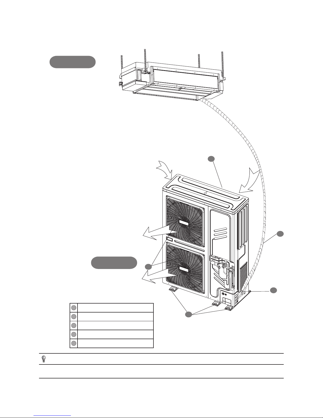
1
Air outlet
2
Air inlet
3
Fixing support
4
Refrigerant pipework connector
4
Connection pipework
Fig. 1
NOTE
All the pictures in this manual are for explanation purposes only. They may be slightly different from the air conditioning unit you have purchased (dependent on
model).
Indoor unit
Outdoor unit
MDCI Series – All DC Inverter Outdoor Units (Three phase) 6 720 862 442 (2016/04)
IMPORTANT SAFETY INFORMATION | 3
1. IMPORTANT SAFETY INFORMATION
To prevent injury or property damage, the following instructions must
be followed. Incorrect operation due to the instructions in this manual
not being followed may cause harm or damage.
The safety precautions listed here are divided into two categories. In either
case, important safety information is listed which must be read carefully.
WARNING
Failure to observe these warnings may result in serious injury.
Only qualified personnel should work on this system.
CAUTION
Failure to observe a caution may result in injury or damage to the
equipment.
WARNING
Before servicing this equipment, ensure the electricity power
supply has been isolated.
Never allow the indoor unit or the remote controller to get wet.
It may cause an electric shock.
Never press the buttons on the remote controller with a hard,
pointed object.
The remote controller may be damaged.
Never replace fuse with incorrect size.
Never use copper wire to replace fuse. This may cause serious injury
or damage.
Where oil, gas, salty air(near the coast), caustic gas exist, this
may damage the unit and shorten the life span of the unit. If the
above locations can‘t be avoided, ensure you apply anti corrosion
to protect the heat exchanger.
When the unit is running fans will be operating.
Keep hands away from fan blades to prevent injury.
Ensure cleaning products do not come into contact with any of the
units electrical components.
Caution should also be taken when using any other flammable or
corrosive products close to the unit.
Never put any objects into the air inlet or outlet.
Objects touching the fan at high speed can be dangerous.
Never inspect or service the unit by yourself.
Ask a qualified person to perform this work.
When disposing the products, consult with local
authorities for special disposal.
When a system is installed in a small room, install leak
detection equipment.
Should refrigerant come in to contact with a naked flame, the gas
can be extremely harmful.
Should a refrigerant leak occur, switch off the power to the air
conditioning unit. Turn off any combustible heating devices,
ventilate the room and contact a competent person.
Do not use the air conditioning unit until a qualified person has been to
correct the fault.
CAUTION
Prior to performing any maintenance work, ensure the unit is
switched off and the electrical power supply has been isolated.
Ensure all of the equipment has been grounded.
Do not remove the fan guard until the unit has been switched off
and the electrical power supply has been safely isolated.
CONTENTS PAGE
IMPORTANT SAFETY INFORMATION ............................................ 3
DESCRIPTION OF UNIT ............................................................... 4
OPEARTING CONDITIONS .......................................................... 5
OPERATION AND PERFORMANCE ...............................................5
ERROR CODES ........................................................................... 6
NORMAL OPERATION OF UNIT .................................................... 7
TROUBLESHOOTING .................................................................. 7
6 720 862 442 (2016/04) MDCI Series – All DC Inverter Outdoor Units (Three phase)
4 | DESCRIPTION OF UNIT
Ensure hands are free from contaminants and are dry prior to performing
any electrical maintenance work.
Do not touch the heat exchanger fins.
These fins are sharp and could cause injury. If the fins are damaged, this will
affect the heat exchange performance.
Do not place items which might be damaged by moisture under the
indoor unit.
Condensation may form if the humidity is above 80%, the drain outlet is
blocked or the filter is dirty.
Ensure condense drainage has a consistent fall away from the unit.
Ensure you do not touch internal parts of the controller.
This could result in serious injury.
Do not use air conditioner where chemicals or gases can affect your
health.
This appliance should only be used by a competent person. Failure to
comply with these instructions may cause serious injury or damage.
When the total capacity of the indoor unit exceeds 100%, ensure the
indoor unit is attenuated.
When the capacity of the indoor unit is greater than or equal to the sum
of 120%, in order to ensure effectiveness of the indoor unit, ensure you
turn the indoor unit on one at a time.
The outdoor unit should be maintained periodically to ensure long life
span of the equipment.
Ensure the communication signal wires do not touch bare copper pipework. The refrigerant circuit will get hot and melt the cables.
2. DESCRIPTION OF UNIT
The air conditioning system consists of an outdoor unit, indoor
units, connective pipework and a way of controlling the system
(remote controller). (see Fig. 1)
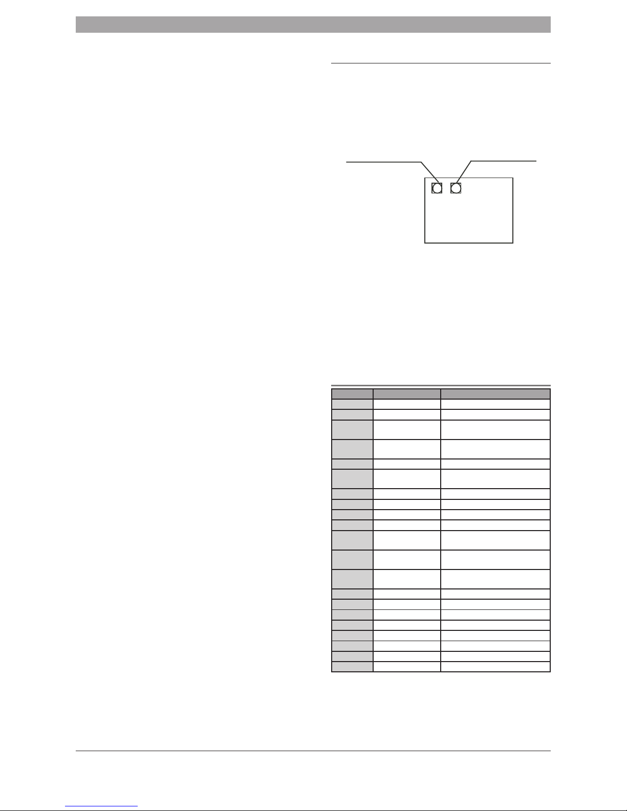
Force Cooling Control
Force cooling control
Button sw1
Display control
button sw2
MAIN BOARD
(OUTDOOR UNIT)
sw1
sw2
Force Cooling Control Fig. 2-1
Force cooling control of the outdoor unit is to be pressed when test running.
The unit will start in cooling and once the outdoor unit changes to 62 Hz the
running of the indoor unit will run in high speed. Press the button again to exit
forced cooling mode.
Display function
SW2 on the main control board of the outdoor unit is the inspection function
button (as shown in Figure 2-1). Pressing this button once displays the first
parameter.
Additional button presses will display other parameters following the
sequence shown in Table 2-1.
Table 2-1
Sequence Displayed content Normal display
Current frequency
1
0--
Local capacity of outdoor units
2
1--
Total capacity requirements of
outdoor units
3
2--
Total requirements of outdoor units
corrected capacity
4
3--
Operating mode
5
4--
Operating FAN speed and FAN
grade
6
5--
T2B/T2 average temperature
7
6--
T3 pipe temperature
8
7--
T4 environment temperature
9
8--
Inverter exhaust temperature
10
9--
Non-inverter exhaust temperature
(reserved)
11
0--
Heat dissipator surface
temperature (reserved)
12
1--
Electronic expansion valve
aperture
13
2--
Inverter input current
14
3--
Non-inverter input current
15
4--
Exhaust pressure (reserved)
16
5--
Priority mode
17
6--
Indoor unit quantity
18
7--
Quantity of working indoor units
19
8--
Last fault or protection code
20
9--
--
 Loading...