

Bosch LH3-UC25XL Specsheet
Communications Systems | LH3-UC25XL EX Flameproof Horn Loudspeaker Long Flare
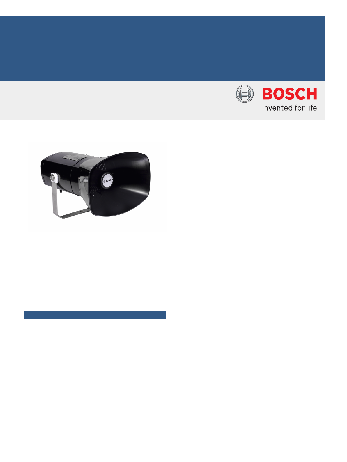
LH3-UC25XL EX Flameproof Horn
Loudspeaker Long Flare
www.boschsecurity.com
u ATEX, IECEx, UL, CSA , and INMETRO certified
u Constructed from sturdy, lightweight, anti-static
Polyamid material
The LH3-UC25XL horn loudspeaker is specifically
designed and certified for installations where
explosive gas-air mixtures are likely to be present. The
horn is constructed from anti-static Polyamid material,
making the horn sturdy and light weighted. The longer
flare design of the horn results in a higher sound
pressure level where longer distance areas can be
covered.
Functions
The horn loudspeaker is standard supplied with a
sturdy stainless steel mounting bracket allowing the
sound beam to be accurately directed.
The mounting bracket has a ratchet facility to ensure it
stays correctly positioned.
The connection cable is fed out through an ABS EX
cable gland (M20) in the rear cover, which can be
removed for entering the inside connection terminal
block. For loop through connection, the rear cover is
fitted with a second hole (covered with a blanking plug
as standard supplied).
The horn loudspeaker includes a transformer for 100 V
input voltage, with taps on the primary winding for
different power settings.
u Water- and dust-protected to class IP67
u Provision for connection of the optional supervision
boards
The different power taps can easily be selected by
connecting to the appropriate terminal of the 6-way
terminal block.
For enabling loudspeaker supervision, a wire loop from
the secondary side of the horn loudspeaker is available
in the connection area. This wire loop is normally
closed, but if used with the supervision board, cut and
connected.
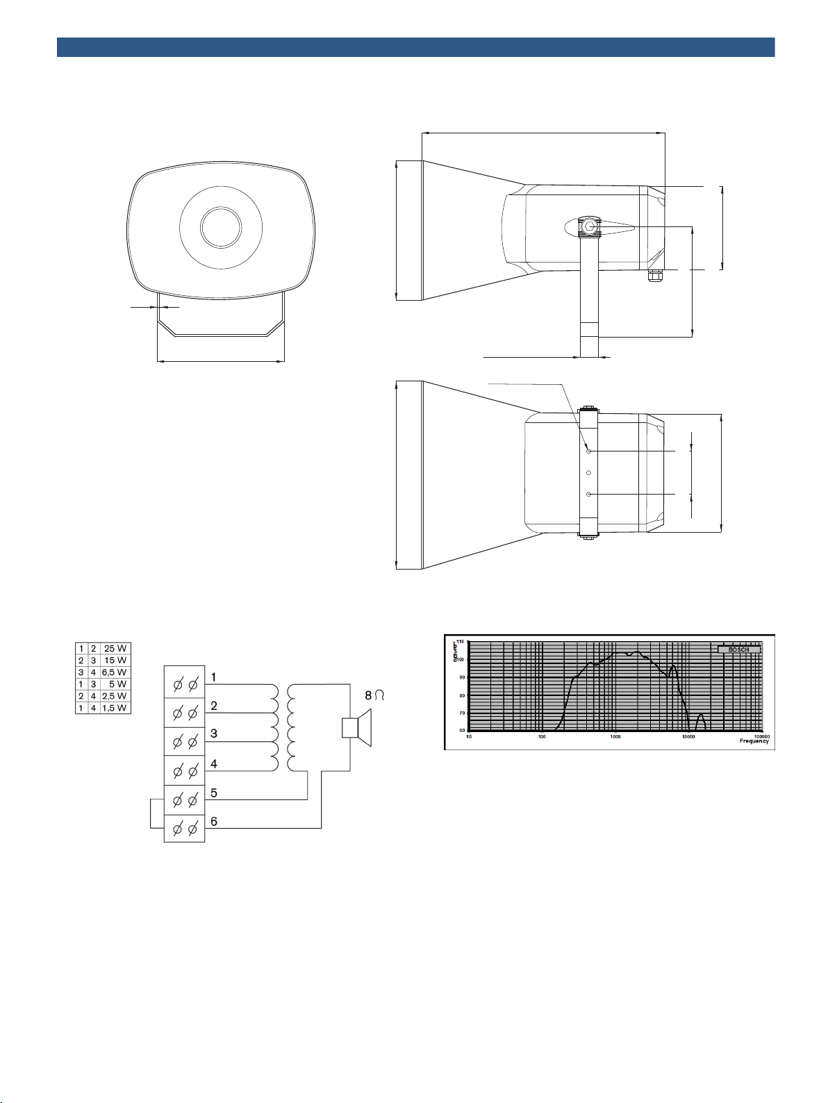
348 mm (13.70”)
200 mm (7.87”)
275 mm (10.82”)
120 mm (4.72”)
156 mm (6.14”)
170 mm (6.69”)
180 mm (7.09”)
3 mm (0.12”)
60 mm (2.36”)
25 mm (0.98”)
7 mm (0.28”)
2 | LH3-UC25XL EX Flameproof Horn Loudspeaker Long Flare
Dimensions in mm (inch)
Circuit diagram
Frequency response
 Loading...