

Page 1
IMPORTANT: IMPORTANT : IMPORTANTE:
Read Before Using Lire avant usage Leer antes de usar
Operating/Safety Instructions
Consignes de fonctionnement/sécurité
Instrucciones de funcionamiento y seguridad
For English Version
Version française
Versión en español
See page 2 Voir page 12 Ver la página 22
1-877-BOSCH99 (1-877-267-2499) www.boschtools.com
Call Toll Free for
Consumer Information
& Service Locations
Pour obtenir des informations
et les adresses de nos centres
de service après-vente,
appelez ce numéro gratuit
Llame gratis para
obtener información
para el consumidor y
ubicaciones de servicio
JS5
BM 2609932576 11-07 11/26/07 11:36 AM Page 1
Page 2

-
2
-
Work area safety
Keep work area clean and well lit.
Cluttered or dark areas invite accidents.
Do not operate power tools in explosive
atmospheres, such as in the presence of
flammable liquids, gases or dust.
Power
tools create sparks which may ignite the dust
or fumes.
Keep children and bystanders away while
operating a power tool.
Distractions can
cause you to lose control.
Electrical safety
Power tool plugs must match the outlet.
Never modify the plug in any way. Do not
use any adapter plugs with earthed
(grounded) power tools.
Unmodified plugs
and matching outlets will reduce risk of
electric shock.
Avoid body contact with earthed or
grounded surfaces such as pipes,
radiators, ranges and refrigerators.
There
is an increased risk of electric shock if your
body is earthed or grounded.
Do not expose power tools to rain or wet
conditions.
Water entering a power tool will
increase the risk of electric shock.
Do not abuse the cord. Never use the cord
for carrying, pulling or unplugging the
power tool. Keep cord away from heat, oil,
sharp edges or moving parts.
Damaged or
entangled cords increase the risk of electric
shock.
When operating a power tool outdoors,
use an extension cord suitable for
outdoor use.
Use of a cord suitable for
outdoor use reduces the risk of electric
shock.
Do not use AC only rated tools with a DC
power supply.
While the tool may appear to
work, the electrical components of the AC
rated tool are likely to fail and create a
hazard to the operator.
If operating the power tool in damp
locations is unavoidable a Ground Fault
Circuit Interrupter (GFCI) must be used to
supply the power to your tool.
GFCI and
personal protection devices like electrician’s
rubber gloves and footwear will further
enhance your personal safety.
Personal safety
Stay alert, watch what you are doing and
use common sense when operating a
power tool. Do not use a power tool while
you are tired or under the influence of
drugs, alcohol or medication.
A moment of
inattention while operating power tools may
result in serious personal injury.
Use safety equipment. Always wear eye
protection.
Safety equipment such as dust
mask, non-skid safety shoes, hard hat, or
hearing protection used for appropriate
conditions will reduce personal injuries.
Avoid accidental starting. Ensure the
switch is in the off-position before
plugging in.
Carrying power tools with your
finger on the switch or plugging in power
tools that have the switch on invites
accidents.
Remove any adjusting key or wrench
before turning the power tool on.
A wrench
or a key left attached to a rotating part of the
power tool may result in personal injury.
Do not overreach. Keep proper footing
and balance at all times.
This enables
better control of the power tool in unexpected
situations.
Dress properly. Do not wear loose
clothing or jewelry. Keep your hair,
clothing and gloves away from moving
parts.
Loose clothes, jewelry or long hair can
be caught in moving parts.
If devices are provided for the connection
of dust extraction and collection facilities,
ensure these are connected and properly
used.
Use of these devices can reduce dust-
related hazards.
Read all instructions. Failure to follow all instructions listed below may
result in electric shock, fire and/or serious injury.
The term “power tool” in
all of the warnings listed below refers to your mains-operated (corded) power tool or batteryoperated (cordless) power tool.
SAVE THESE INSTRUCTIONS
!
WARNING
General Safety Rules
BM 2609932576 11-07 11/26/07 11:36 AM Page 2
Page 3

-3-
Safety Rules for Jigsaws
Hold power tools by insulated gripping
surfaces when performing an operation
where the cutting tool may contact hidden
wiring or its own cord.
Contact with a "live"
wire will make exposed metal parts of the
tool "live" and shock the operator.
Do not
drill, fasten or break into existing walls or
other blind areas where electrical wiring may
exist. If this situation is unavoidable,
disconnect all fuses or circuit breakers
feeding this worksite.
Never leave the trigger locked "ON".
Before plugging the tool in, check that the
trigger lock is "OFF".
Accidental start-ups
could cause injury.
Be aware of the location and setting of
the switch "Lock-ON" button.
If the switch
is locked "ON" during the use, be ready for
emergency situations to switch it "OFF", by
first pulling the trigger then immediately
releasing it without pressing the "Lock-ON"
button.
Keep handles dry, clean and free from oil
and grease.
Slippery hands cannot safely
c
ontrol the power tool.
Power tool use and care
Do not force the power tool. Use the
correct power tool for your application.
T
he correct power tool will do the job better
and safer at the rate for which it was
designed.
Do not use the power tool if the switch
does not turn it on and off.
Any power tool
that cannot be controlled with the switch is
dangerous and must be repaired.
Disconnect the plug from the power
source and/or the battery pack from the
power tool before making any
adjustments, changing accessories, or
storing power tools.
Such preventive safety
measures reduce the risk of starting the
power tool accidentally.
Store idle power tools out of the reach of
children and do not allow persons
unfamiliar with the power tool or these
instructions to operate the power tool.
Power tools are dangerous in the hands of
untrained users.
Maintain power tools. Check for
misalignment or binding of moving parts,
breakage of parts and any other condition
that may affect the power tools operation.
If damaged, have the power tool repaired
before use.
Many accidents are caused by
poorly maintained power tools.
Keep cutting tools sharp and clean.
Properly maintained cutting tools with sharp
cutting edges are less likely to bind and are
easier to control.
Use the power tool, accessories and tool
bits etc., in accordance with these
instructions and in the manner intended
for the particular type of power tool,
taking into account the working
conditions and the work to be performed.
Use of the power tool for operations different
from those intended could result in a
hazardous situation.
Use clamps or other practical way to
secure and support the workpiece to a
stable platform.
Holding the work by hand
or against your body is unstable and may
lead to loss of control.
Empty dust container frequently,
especially when sanding wood with
polyurethane, varnish, shellac or similarly
coated surface.
Fine particles of sanding
dust may self ignite and cause fire.
Service
Have your power tool serviced by a
qualified repair person using only identical
replacement parts.
This will ensure that the
safety of the power tool is maintained.
Develop a periodic maintenance schedule
for your tool. When cleaning a tool be
careful not to disassemble any portion of
the tool since internal wires may be
misplaced or pinched or safety guard
return springs may be improperly
mounted.
Certain cleaning agents such as
gasoline, carbon tetrachloride, ammonia, etc.
may damage plastic parts.
SAVE THESE INSTRUCTIONS
BM 2609932576 11-07 11/26/07 11:36 AM Page 3
Page 4
-
4
-
Keep hands away from cutting area. Do
not reach under the material being cut.
The proximity of the blade to your hand is
hidden from your sight.
Keep hands from between the gear
housing and saw blade holder.
The
reciprocating blade holder can pinch your
fingers.
Do not use dull or damaged blades. Bent
blade can break easily or cause kickback.
Before starting to cut, turn tool "ON" and
allow the blade to come to full speed.
Tool can chatter or vibrate if blade speed is
too slow at beginning of cut and possibly
kickback.
Always wear safety goggles or eye
protection when using this tool. Use a
dust mask or respirator for applications
which generate dust.
Secure material before cutting. Never
hold it in your hand or across legs.
Small
or thin material may flex or vibrate with the
blade, causing loss of control.
Make certain all adjusting screws and the
blade holder are tight before making a
cut.
Loose adjusting screws and holders
can cause the tool or blade to slip and loss of
control may result.
When removing the blade from the tool
avoid contact with skin and use proper
protective gloves when grasping the
blade or accessory.
Accessories may be
hot after prolonged use.
If your tool is equipped with a dust bag,
empty it frequently and after completion of
sawing.
Spontaneous combustion, may in
time, result from mixture of oil or water with
dust particles. Be extremely careful of dust
disposal, materials in fine particle form may be
explosive. Do not throw contents on an open
fire.
Some dust created by
power sanding, sawing,
grinding, drilling, and other construction
activities contains chemicals known to
cause cancer, birth defects or other
reproductive harm. Some examples of
these chemicals are:
• Lead from lead-based paints,
• Crystalline silica from bricks and cement
and other masonry products, and
• Arsenic and chromium from chemically-
treated lumber.
Your risk from these exposures varies,
depending on how often you do this type of
work. To reduce your exposure to these
chemicals: work in a well ventilated area, and
work with approved safety equipment, such
as those dust masks that are specially
designed to filter out microscopic particles.
!
WARNING
BM 2609932576 11-07 11/26/07 11:36 AM Page 4
Page 5
-5-
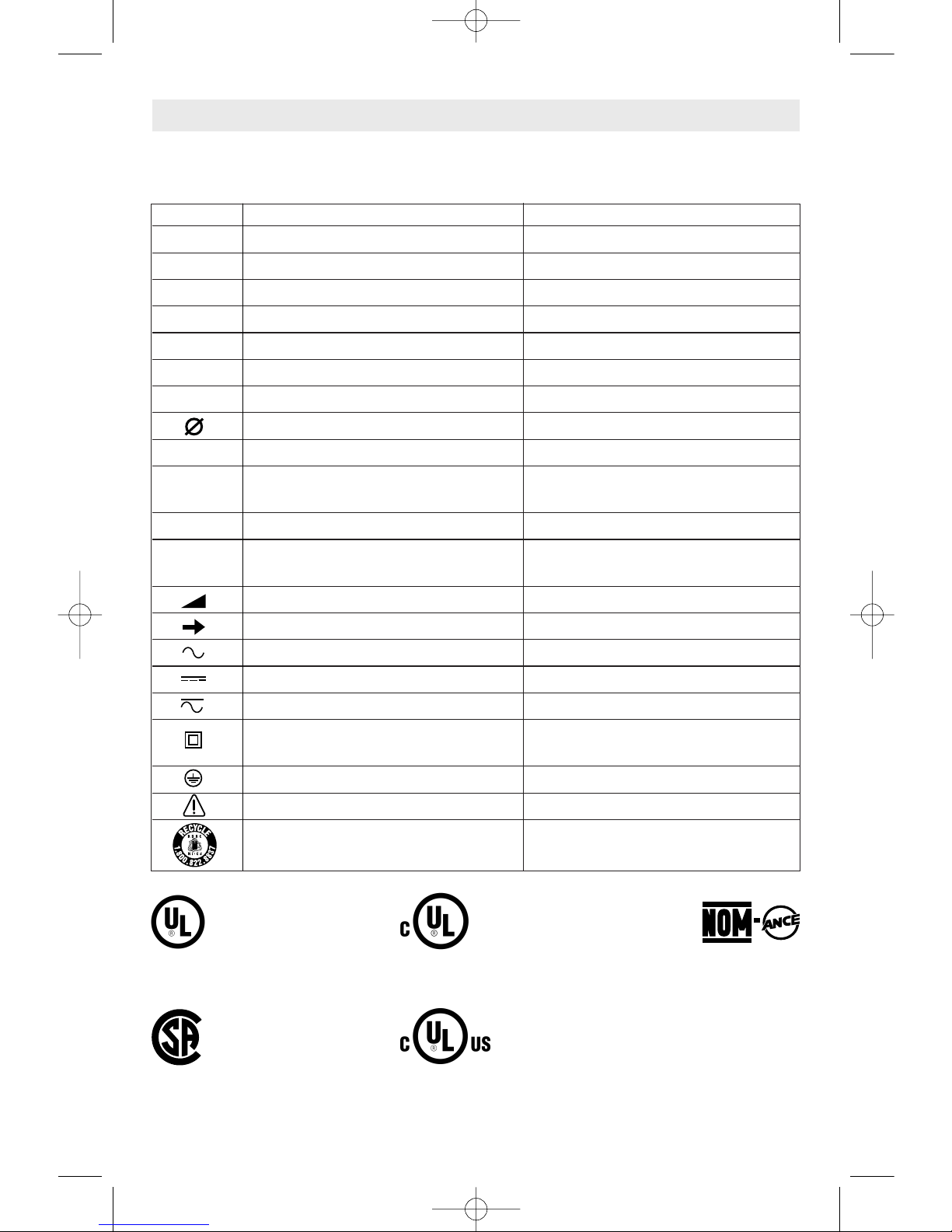
IMPORTANT: Some of the following symbols may be used on your tool. Please study them
and learn their meaning. Proper interpretation of these symbols will allow you to operate the
tool better and safer.
Symbol Name Designation/Explanation
V Volts Voltage (potential)
A Amperes Current
Hz Hertz Frequency (cycles per second)
W Watt Power
kg Kilograms Weight
min Minutes Time
s Seconds Time
Diameter Size of drill bits, grinding wheels, etc.
n
0
No load speed Rotational speed, at no load
.../min Revolutions or reciprocation per minute Revolutions, strokes, surface speed,
orbits etc. per minute
0 Off position Zero speed, zero torque...
1, 2, 3, ... Selector settings Speed, torque or position settings.
I, II, III, Higher number means greater speed
Infinitely variable selector with off Speed is increasing from 0 setting
Arrow Action in the direction of arrow
Alternating current Type or a characteristic of current
Direct current Type or a characteristic of current
Alternating or direct current Type or a characteristic of current
Class II construction Designates Double Insulated
Construction tools.
Earthing terminal Grounding terminal
Warning symbol Alerts user to warning messages
Ni-Cad RBRC seal Designates Ni-Cad battery recycling
program
Symbols
0
This symbol designates
that this tool is listed by
Underwriters Laboratories.
This symbol designates
that this tool is listed by
the Canadian Standards
Association.
This symbol designates
that this tool is listed to
Canadian Standards by
Underwriters Laboratories.
This symbol
designates
that
this tool
complies
to NOM
Mexican
Standards.
This symbol designates that
this tool is listed by
Underwriters Laboratories,
and listed to Canadian
Standards by Underwriters
Laboratories.
BM 2609932576 11-07 11/26/07 11:36 AM Page 5
Page 6
-
6
-
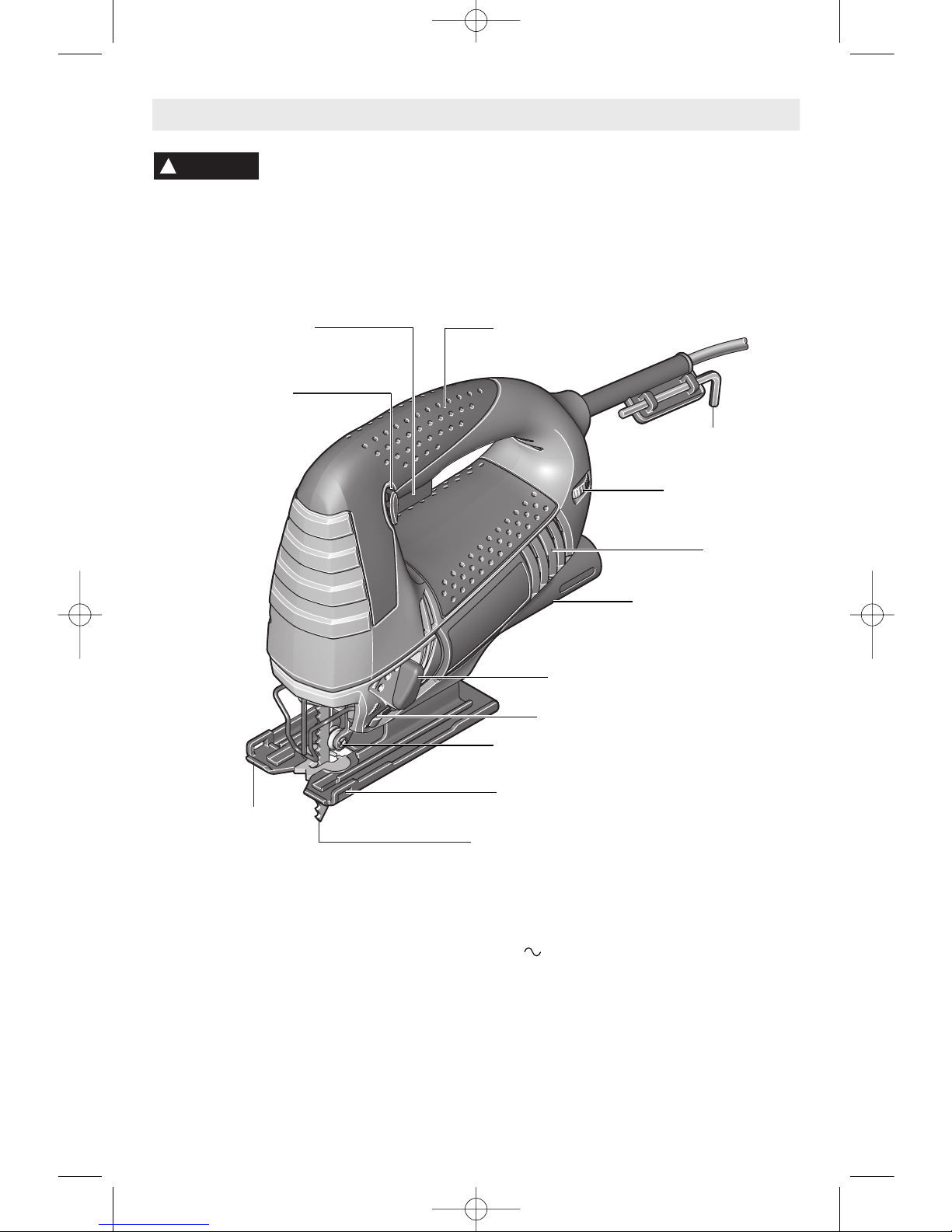
Functional Description and Specifications
Disconnect the plug from the power source before making any
assembly, adjustments or changing accessories
. Such preventive safety
measures reduce the risk of starting the tool accidentally.
!
WARNING
Jigsaw
"LOCK-ON" BUTTON
TRIGGER SWITCH
ALLEN WRENCH
5 MM
VENTILATION
OPENINGS
CHIP BLOWER SWITCH
BLADE ROLLER GUIDE
BLADE ORBIT SELECTOR LEVER
CUTTING GUIDE SLOTS
BLADE
BASE
VARIABLE SPEED
DIAL
RUBBERIZED
GRIP
DUST PORT
Model number
JS5
Voltage rating 120 V 50 - 60Hz
Amperage rating 5.7 A
No load speed n
0
500-3,100/min
Stroke length
7/8
"
Wood 3-9/16"
Aluminium 3/4"
Steel
3/8
"
BM 2609932576 11-07 11/26/07 11:36 AM Page 6
Page 7
-7-
Assembly
BLADE INSTALLATION AND REMOVAL
T
his jigsaw is equipped with the Bosch “One
Touch” tool-less blade changing system.
This system makes changing blades simple
and fast.
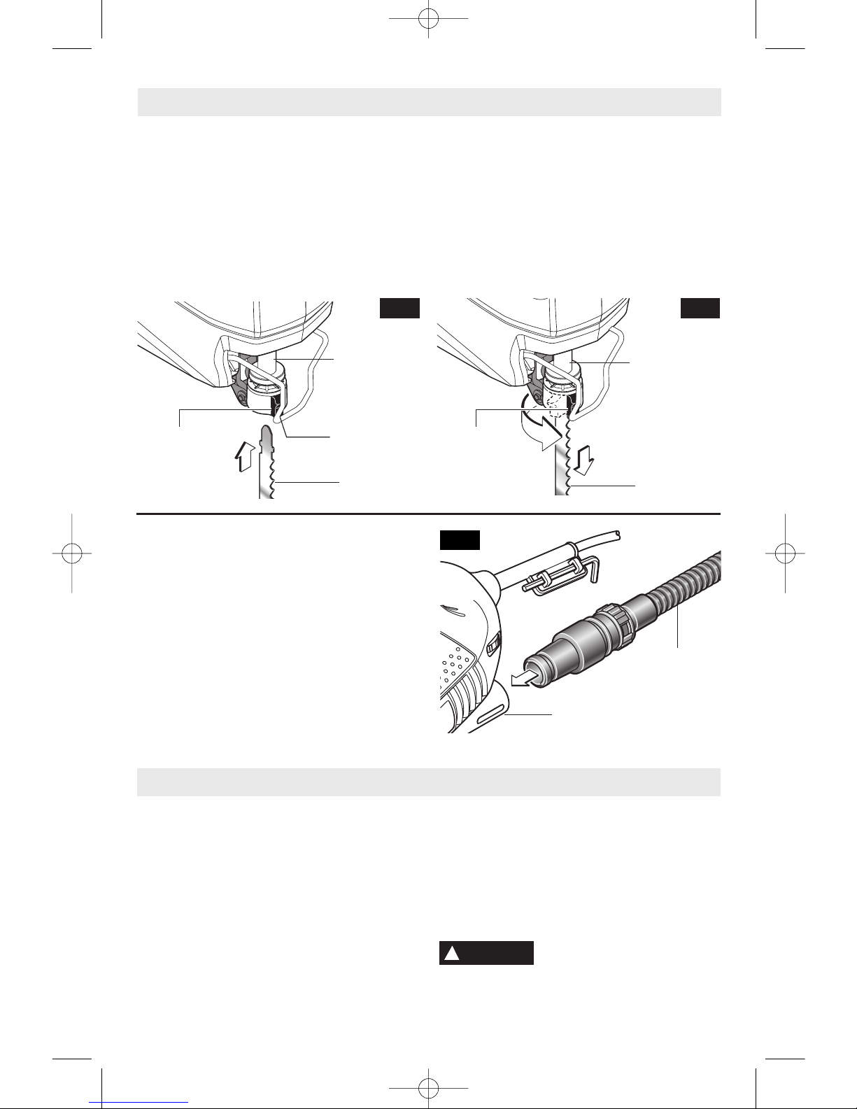
Insert the saw blade (teeth in cutting
direction) until it latches in the plunger
(Fig. 2.) When inserting the saw blade, the
back of the blade must rest in the groove of
the guide roller To prevent damage to tool,
d
o not manually turn blade ejector lever
when inserting the blade
To change the saw blade, push the ejector
lever to the center stop; this releases and
ejects the saw blade (Fig. 3).
When changing the blade, tool should be
held so that the blade is safely ejected.
BLADE
PLUNGER
BLADE
EJECTOR
LEVER
BLADE
BLADE
PLUNGER
BLADE
EJECTOR
LEVER
BLADE
FIG. 2 FIG. 3
DUST EXTRACTION
Your tool is equipped with a dust port for dust
extraction. To use this feature, attach
vacuum hose (optional accessory) to the dust
port, and connect the opposite end of the
hose to a shop vacuum cleaner (Fig. 4).
FIG. 4
VARIABLE SPEED CONTROLLED
TRIGGER SWITCH
Your tool is equipped with a variable speed trigger
switch. The tool can be turned "ON" or "OFF" by
squeezing or releasing the trigger. The speed
can be adjusted from the minimum to maximum
nameplate RPM by the pressure you apply to the
trigger. Apply more pressure to increase the
speed and release pressure to decrease speed.
"LOCK-ON" BUTTON
The "Lock-ON" button, located in the handle of
your tool allows for continuous operation at
maximum RPM without holding the trigger.
TO LOCK TRIGGER "ON": squeeze trigger,
depress button and release trigger.
TO UNLOCK THE TRIGGER: squeeze trigger
and release it without depressing the "LockON" button.
If the “Lock-ON” button is
continuously being depressed,
the trigger can not be released.
Operating Instructions
!
WARNING
DUST PORT
VACUUM HOSE
(OPTIONAL
ACCESSORY)
BLADE
EJECTOR
LEVER
BM 2609932576 11-07 11/26/07 11:36 AM Page 7
Page 8
-8-
FOOTPLATE ANGLE ADJUSTMENT
The footplate may be tilted to allow angle cuts
up to 45˚ in either direction. To adjust footplate,
loosen screw with allen wrench, slide the
footplate towards the front of the tool, and
rotate to the desired angle, as marked on the
angle scale (Fig. 5). Detent slots will hold the
footplate firmly at 45˚, and there are additional
position marks for 15˚ and 30˚ angles.
Intermediate angles may be set with a
protractor. After positioning the footplate,
securely tighten screw).
VARIABLE SPEED DIAL
Your Jigsaw is equipped with a variable speed
dial. The blade stroke rate may be adjusted
d
uring cutting operation by presetting the dial
on or between any one of the six numbers.
Setting
1
-2 Low stroke
3-4 Medium stroke
5-6 High stroke
PLUNGER SPEED
The jigsaw cutting speed or stroke rate
required depends on the material being cut, the
type of blade used, and the feed rate preferred
by the operator. The best speed for a particular
application is largely determined by experience,
though as a general rule, slower speeds are for
denser materials and faster speeds for soft
materials. Note that when the jigsaw is used at
low speed settings for any length of time, the
motor temperature will rise due to the slower
speed of the internal cooling fan. In such
cases, it is necessary to occasionally run the
tool at full speed for a few minutes to keep the
motor operating at high efficiency.
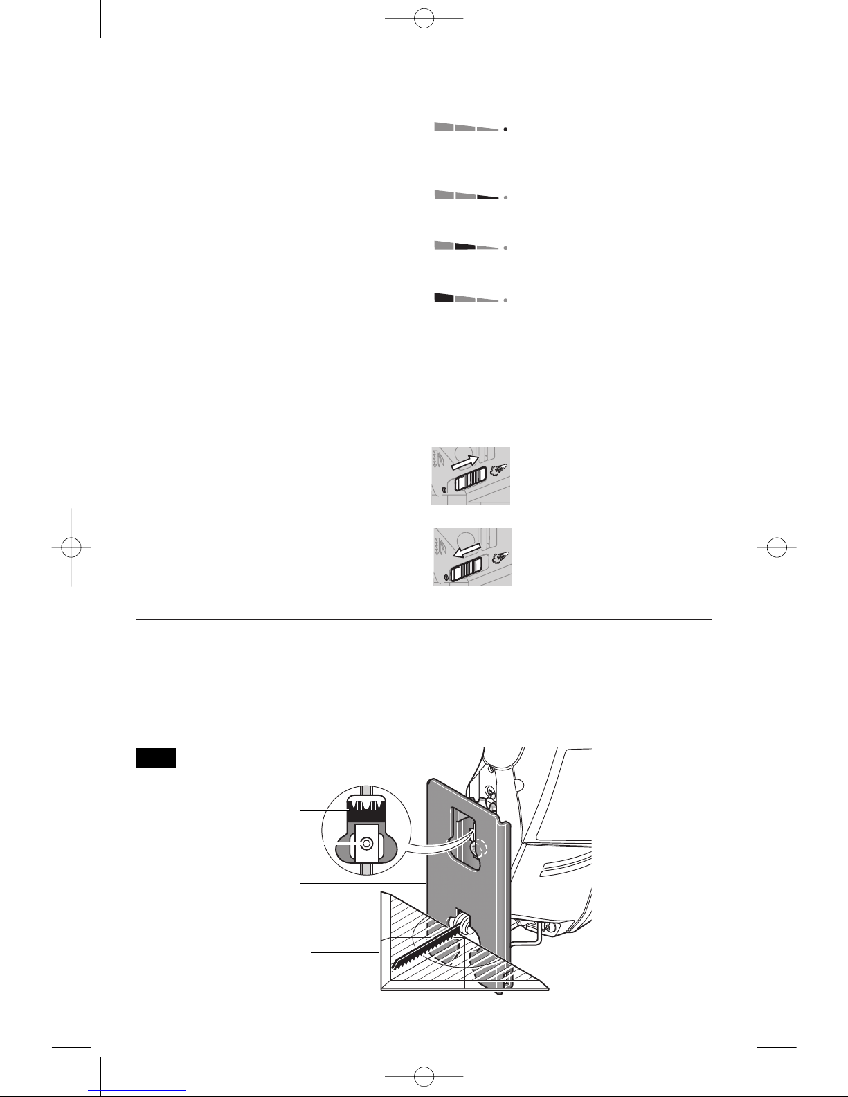
BLADE ORBIT
Maximum cutting efficiency can be obtained by
adjusting the blade orbit selector lever to suit
the material being cut. The following chart will
help you determine which setting to use for
your application. This chart is intended as a
guideline only, and test cuts in scrap material
should be performed first to determine the best
setting.
hard materials such as metals
or thin sheet metals and used
with knife blades, grit edge
blades or rasp work
soft materials where cleaner
cutting or delicate scrolling
work is performed
medium density materials
such as harder woods or
particle board
soft materials such as wood,
plastics, etc.
CHIP BLOWER
Your jigsaw is equipped with a two position
chip blower to help keep the cutting line clear
of chips.
By adjusting the chip blower lever the force
of the discharge air may be altered as
follows;
BLOWER SWITCHED ON
For working with wood, plastic
and similar materials that
produce large amounts of
sawdust.
BLOWER SWITCHED OFF
For working with metals and
when cooling agents are used,
or with dust collection accessory.
FIG. 5
0
15
30
45
15
30
45
DETENT SLOTS
ANGLE
SCALE
SCREW
FOOTPLATE
PROTRACTOR
(Not included)
BM 2609932576 11-07 11/26/07 11:36 AM Page 8
Page 9
-9-
ANTI-SPLINTER INSERT
To minimize splintering of the top surface of the
m
aterial being cut, place the anti-splinter insert
in the blade opening of the footplate (Fig. 6).
Note: This insert will only work with blades that
have ground sides such as T301CD, T101B,
T101D, and T101DP.
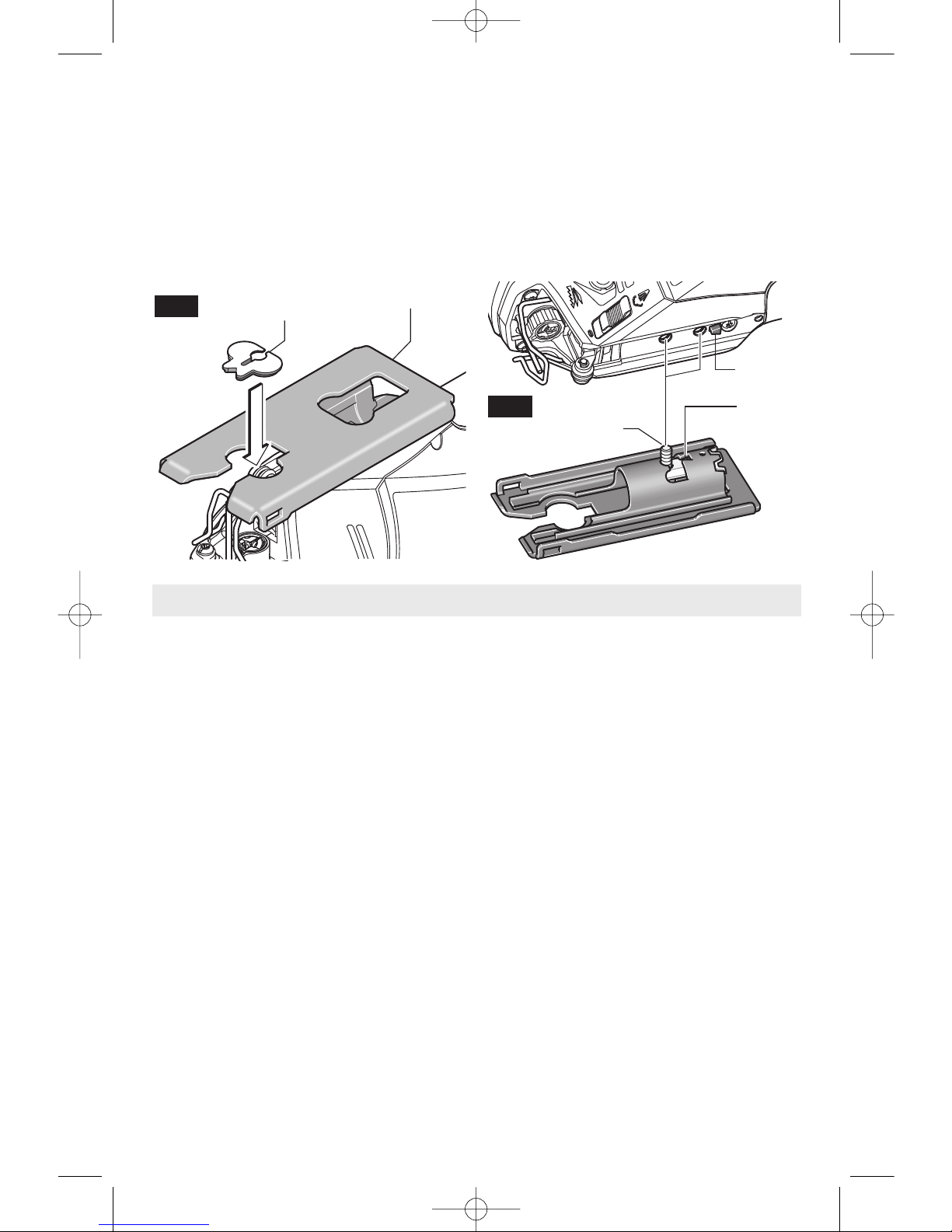
FLUSH CUTTING
To allow the saw to make a perpendicular cut
close to a vertical surface, the footplate may be
repositioned as follows. Remove screw, move
footplate to the front mounting slot, and be sure
t
he detent notch is aligned with the detent slot
in the footplate. Re-insert screw into the
threaded hole closest to the detent notch, and
securely tighten (Fig. 7). Note that when the
footplate is retracted in this manner, only
90˚cuts are possible, and optional cutting guide
may not be used.
ANTI-SPLINTER
INSERT
FOOTPLATE
FIG. 6
SCREW
DETENT
NOTCH
DETENT
NOTCH
FIG. 7
Always be certain that smaller workpieces are
securely fastened to a bench or other support.
Larger panels may be held in place by clamps
on a bench or sawhorses.
To begin a cut, clearly mark the cutting line,
and rest the front of the footplate on the work.
Engage the switch, and move the blade into the
work using only enough forward pressure to
keep the blade cutting steadily. DO NOT
FORCE, as this will not make the saw cut
faster; let the blade do the work.
When cutting metal, it is often advisable to use
a lubricant to cool the blade and extend its life.
Choose blades carefully, as the ability of the
jigsaw to follow curves, provides smoother
finishes, or faster cutting is directly related to
the type of blade used.
BLADE SELECTION
• Choose blades carefully, as the ability of the
jigsaw to make the fastest cuts, to follow tight
curves, to achieve the smoothest finish and/or
to maximize the life of the blade are directly
related to the type of blade used.
• Always use a blade that is appropriate for the
cutting task.
• Always make a test cut in a piece of scrap material.
• Most jigsaw blades have upward-pointing
teeth, which helps to pull the jigsaw against the
workpiece and minimizes vibration. Blades with
upward-pointing teeth produce a clean cut on
the bottom of the workpiece.
• Blades with downward-pointing teeth
(reverse-tooth blade) can be used to produce a
clean cut on the top of the workpiece (that side
that faces the jigsaw's footplate), such as when
cutting an already-installed countertop from the
top. When using reverse-tooth blades,
downward force must be applied to the jigsaw.
• Blades with teeth that point straight out (rather
than up or down) allow splinter-free cutting on
both sides of the workpiece. When using such
blades, downward force must be applied to the
jigsaw.
• The following types of blades should only be
used with orbital Setting O:
1. Blades with teeth that point downward
(reverse-tooth blades).
2. Blades with teeth that point straight out
rather than up or down.
3. Carbide-tipped blades.
4. Grit-edge blades.
Tool Tips
BM 2609932576 11-07 11/26/07 11:36 AM Page 9
Page 10
-10-
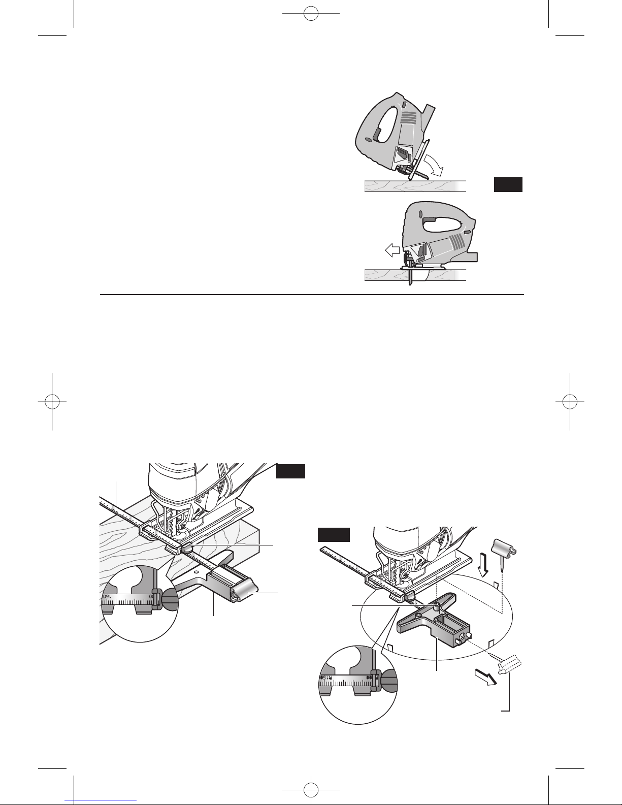
PLUNGE CUTTING
P
lunge cutting is useful and time-saving in
m
aking rough openings in softer materials. It is
not necessary to drill a hole for an inside or
pocket cut. Draw lines for the opening, hold the
saw firmly, tilt it forward so that the toe of the
saw foot rests on the work, but with the blade
well clear of the work. Start the motor, and
then very gradually lower the blade. When it
touches, continue pressing down on the toe of
the saw foot slowly pivoting the saw like a
hinge until the blade cuts through and the foot
rests flat on the work. Then saw ahead on the
cutting line. We do not recommend plunge
cutting with a scroll blade (Fig. 8).
To make sharp corners, cut up to the corner,
then back up slightly before rounding the
corner. After the opening is complete, go back
to each corner and cut it from the opposite
direction to square it off. Do not try to plunge
c
ut into hard materials such as steel.
FIG. 8
CIRCLE AND PARALLEL CUTTING GUIDE
(Not included, available as accessory)
This accessory is available at an extra cost. It
is used for fast and accurate straight and
circle cutting (Fig.9).
PARALLEL CUTTING
1. Insert bar of guide through lock knob clamp,
then through the slots provided in foot, from
either side of foot with the edge guide facing
DOWN (Fig. 9).
2. Hook lock knob clamp onto edge of
footplate, adjust fence to desired width, and
securely tighten lock knob clamp (Fig. 9).
CIRCLE CUTTING
1. Before attaching the guide, draw a circle
and predrill a 13/64” center hole in workpiece
.
2. Drill or plunge cut near the circles edge,
turn saw off and disconnect the plug from
power source.
3. Attach guide to saw with edge guide facing
UP as shown (Fig. 10).
4. Remove guide pin from end of guide, push
pin through hole provided in guide, then into
center hole of workpiece.
5. Measure the distance from the selected
hole to the blade to be equal to the circle
radius.
6. Insert plug into power source, hold the saw
firmly, squeeze trigger and slowly push the
saw forward. To make a hole, cut from inside
the circle; To make wheels or discs, cut from
the outside.
Cutting Tip: Cut slowly so the blade will stay
straight in the cut. Place small wedges in the
cut as shown in Fig. 10, to keep the inner
circle from spreading when near the end of
the cut.
FIG. 9
LOCK
KNOB
CLAMP
GUIDE
PIN
EDGE GUIDE
DOWN
BAR
1
2
GUIDE PIN
EDGE
GUIDE UP
FIG. 10
GUIDE PIN
HOLE
BM 2609932576 11-07 11/26/07 11:36 AM Page 10
Page 11

-11-
Service
Preventive maintenance
performed by unauthorized
personnel may result in misplacing of
i
nternal wires and components which
could cause serious hazard.
We
recommend that all tool service be performed
by a Bosch Factory Service Center or Authorized Bosch Service Station.
TOOL LUBRICATION
Your Bosch tool has been properly lubricated
and is ready to use. It is recommended that
tools with gears be regreased with a special
gear lubricant at every brush change.
CARBON BRUSHES
The brushes and commutator in your tool
have been engineered for many hours of
dependable service. To maintain peak
efficiency of the motor, we recommend every
two to six months the brushes be examined.
Only genuine Bosch replacement brushes
specially designed for your tool should be
used.
BEARINGS
After about 300-400 hours of operation, or at
every second brush change, the bearings
should be replaced at Bosch Factory Service
Center or Authorized Bosch Service Station.
Bearings which become noisy (due to heavy
load or very abrasive material cutting) should
be replaced at once to avoid overheating or
motor failure.
Cleaning
To avoid accidents always
disconnect the tool from
the power supply before cleaning or
performing any maintenance.
The tool may
be cleaned most effectively with compressed
dry air.
Always wear safety goggles when
cleaning tools with compressed air.
Ventilation openings and switch levers must
be kept clean and free of foreign matter. Do
not attempt to clean by inserting pointed
objects through openings.
Certain cleaning agents
and solvents damage
plastic parts.
Some of these are: gasoline,
carbon tetrachloride, chlorinated cleaning
solvents, ammonia and household
detergents that contain ammonia.
!
WARNING
!
WARNING
Maintenance
Accessories
!
CAUTION
If an extension cord is
necessary, a cord with
adequate size conductors that is capable
of carrying the current necessary for your
tool must be used.
This will prevent
excessive voltage drop, loss of power or
overheating. Grounded tools must use 3wire extension cords that have 3-prong plugs
and receptacles.
NOTE: The smaller the gauge number, the
heavier the cord.
RECOMMENDED SIZES OF EXTENSION CORDS
120 VOLT ALTERNATING CURRENT TOOLS
!
WARNING
* Screwdriver
* Blade locking screw
* Allen wrench 5mm
** Anti-splinter insert (5 pcs.)
** Cutting guide
** Carrying case
(*= standard equipment)
(**= optional accessories)
Tool’s
Ampere
Rating
Cord Size in A.W.G.
Wire Sizes in mm
2
3-6
6-8
8-10
10-12
12-16
18 16 16 14 0.75 0.75 1.5 2.5
18 16 14 12 0.75 1.0 2.5 4.0
18 16 14 12 0.75 1.0 2.5 4.0
16 16 14 12 1.0 2.5 4.0 —
14 12 — — — — — —
25
50 100 150 15 30 60 120
Cord Length in Feet Cord Length in Meters
BM 2609932576 11-07 11/26/07 11:36 AM Page 11
Page 12

-12-
Veuillez lire et comprendre toutes les consignes. Si on n'observe pas toutes les
consignes décrites ci-dessous, il y a risque de choc électrique, d’incendie et/ou
de blessures corporelles graves. Dans toutes les mises en garde ci-dessous, le terme « outil électroportatif »
se rapporte à des outils branchés sur le secteur (avec fil) ou à des outils alimentés par piles (sans fil).
CONSERVEZ CES CONSIGNES
Consignes générales de sécurité
AVERTISSEMENT
!
Sécurité du lieu de travail
Maintenez le lieu de travail propre et bien éclairé.
Les risques d’accident sont plus élevés quand on
travaille dans un endroit encombré ou sombre.
N’utilisez pas d’outils électroportatifs dans des
atmosphères explosives, comme par exemple en
présence de gaz, de poussières ou de liquides
inflammables. Les outils électroportatifs produisent
des étincelles qui risquent d’enflammer les poussières
ou les vapeurs.
Éloignez les enfants et les visiteurs quand vous vous
servez d’un outil électroportatif. Vous risquez une
perte de contrôle si on vous distrait.
Sécurité électrique
Les fiches des outils électroportatifs doivent
correspondre à la prise. Il ne faut absolument jamais
modifier la fiche. N’utilisez pas d’adaptateur de prise
avec des outils électroportatifs munis d’une fiche de
terre. Le risque de choc électrique est moindre si on
utilise une fiche non modifiée sur une prise qui lui
correspond.
Évitez tout contact du corps avec des surfaces reliées
à la terre tels que tuyaux, radiateurs, gazinières ou
réfrigérateurs. Le risque de choc électrique augmente
si votre corps est relié à la terre.
N’exposez pas les outils électroportatifs à la pluie ou
à l’humidité. Si de l’eau pénètre dans un outil
électroportatif, le risque de choc électrique augmente.
Ne maltraitez pas le cordon. Ne vous en servez
jamais pour transporter l’outil électroportatif, pour le
tirer ou pour le débrancher. Éloignez le cordon de la
chaleur, des huiles, des arêtes coupantes ou des
pièces mobiles. Les cordons abîmés ou emmêlés
augmentent les risques de choc électrique.
Si vous utilisez un outil électroportatif à l’extérieur,
employez une rallonge conçue pour l’extérieur. Ces
rallonges sont faites pour l’extérieur et réduisent le
risque de choc électrique.
N’utilisez pas un outil conçu uniquement pour le C.A.
sur une alimentation en C.C. Même si l’outil semble
fonctionner, les composants électriques d’un outil prévu
pour le C.A. tomberont probablement en panne et
risquent de créer un danger pour l’utilisateur.
S’il est nécessaire d’utiliser l’outil dans un lieu
humide, il faut l’alimenter par l’intermédiaire d’un
disjoncteur différentiel de fuite à la terre (DDFT).
L’emploi d’un DDFT et de dispositifs de protection
personnelle tels que gants et chaussures d’électricien
en caoutchouc améliorent votre sécurité personnelle.
Sécurité personnelle
Restez concentré, faites attention à ce que vous
faites, et servez-vous de votre bon sens lorsque vous
utilisez un outil électroportatif. N'employez pas
d’outils électroportatifs quand vous êtes fatigué ou
sous l’emprise de drogues, d’alcool ou de
médicaments. Quand on utilise des outils
électroportatifs, il suffit d’un moment d’inattention pour
causer des blessures corporelles graves.
Utilisez des équipements de sécurité. Portez toujours
une protection oculaire. Si les conditions le
demandent, il faut porter un masque à poussière, des
chaussures de sécurité antidérapantes, un casque de
chantier ou une protection auditive pour réduire le
risque de blessure corporelle.
Évitez les démarrages intempestifs. Assurez-vous
que l’interrupteur est en position arrêt (OFF) avant de
brancher l’outil. Transporter un outil électroportatif
avec le doigt sur la gâchette ou le brancher quand
l’interrupteur est en position “marche” (ON) présente
des risques d’accident.
Enlevez toutes les clés de réglage avant de mettre
l’outil électroportatif en marche. Si on laisse une clé
sur une pièce tournante de l’outil électroportatif, il y a
risque de blessure corporelle.
Ne vous penchez pas. Conservez toujours une bonne
assise et un bon équilibre. Ceci vous permettra de
mieux maîtriser l’outil électroportatif dans des situations
inattendues.
Habillez-vous de manière appropriée. Ne portez pas
de vêtements amples ou de bijoux. Attachez les
cheveux longs. N’approchez pas les cheveux, les
vêtements ou les gants des pièces en mouvement.
Les vêtements amples, les bijoux ou les cheveux longs
risquent d’être happés par les pièces en mouvement.
Si l’outil est muni de dispositifs permettant le
raccordement d’un système d’aspiration et de
collecte des poussières, assurez-vous que ces
dispositifs sont raccordés et utilisés correctement.
L’utilisation de ces dispositifs peut permettre de réduire
les dangers liés à la poussière.
Maintenez les poignées sèches et exemptes d’huile et
de graisse. On ne pas maîtriser un outil électroportatif
en toute sécurité quand on a les mains glissantes.
BM 2609932576 11-07 11/26/07 11:36 AM Page 12
Page 13

-13-
Tenez les outils électroportatifs par les surfaces de
préhension isolées lorsque vous effectuez une
opération à l'occasion de laquelle l'outil de coupe
risque d'entrer en contact avec un fil caché ou avec
son propre cordon d'alimentation. Tout contact avec
un fil sous tension mettra également sous tension les
pièces métalliques de l'outil qui sont exposées et
causera donc un choc électrique pour l'opérateur. Il ne
faut pas percer, assujettir ou casser des murs ou
d'autres structures sans visibilité à l'intérieur desquels
des fils électriques peuvent se trouver. S'il n'est pas
possible d'éviter une telle situation, déconnectez tous
les fusibles ou disjoncteurs des circuits alimentant ce
lieu de travail
Ne laissez jamais la gâchette verrouillée en position
de marche (« ON »). Avant de brancher l'outil,
assurez-vous que le verrou de la gâchette est dans la
position « OFF » (Désactivée). Des mises en marche
accidentelles risqueraient de causer des blessures.
Assurez-vous que vous savez toujours où se trouve le
bouton de l'interrupteur « Lock-ON » (Verrouillage
activé) et dans quelle position il se trouve. Si
l'interrupteur est verrouillé dans la position « ON »
(Activée) pendant l'emploi de l'outil, soyez prêt à le
faire passer dans la position « OFF » (Désactivée) en
cas d'urgence ; pour ce faire, tirez d'abord sur la
gâchette, puis relâchez-la immédiatement sans
appuyer sur le bouton « Lock-ON » (Verrouillage
activé).
Consignes de sécurité pour les scies à chantourner
Utilisation et entretien des outils
électroportatifs
Ne forcez pas sur l’outil électroportatif. Utilisez l’outil
électroportatif qui convient à la tâche à effectuer.
L’outil qui convient à la tâche fait un meilleur travail et
est plus sûr à la vitesse pour lequel il a été conçu.
Ne vous servez pas de l’outil électroportatif si son
interrupteur ne parvient pas à le mettre en marche ou
à l’arrêter. Tout outil électroportatif qui ne peut pas
être commandé par son interrupteur est dangereux et
doit être réparé.
Débranchez la fiche de la prise ou enlevez le bloc-pile
de l’outil électroportatif avant tout réglage,
changement d’accessoires ou avant de ranger l’outil
électroportatif. De telles mesures de sécurité
préventive réduisent le risque de démarrage intempestif
de l’outil électroportatif.
Rangez les outils électroportatifs dont vous ne vous
servez pas hors de portée des enfants et ne permettez
pas à des personnes qui ne connaissent pas l’outil
électroportatif ou qui ignorent ces consignes de s’en
servir. Les outils électroportatifs sont dangereux dans
les mains d’utilisateurs inexpérimentés.
Entretenez les outils électroportatifs. Vérifiez que les
pièces mobiles sont alignées correctement et ne
coincent pas. Vérifiez qu’il n’y a pas de pièces
cassées ou d’autre circonstance qui risquent
d’affecter le fonctionnement de l’outil électroportatif.
Si l’outil est abîmé, faites-le réparer avant de
l’utiliser. De nombreux accidents sont causés par des
outils électroportatifs mal entretenus.
Maintenez les outils coupants affûtés et propres. Les
outils coupants entretenus correctement et dotés de
bords tranchants affûtés sont moins susceptibles de
coincer et sont plus faciles à maîtriser.
Utilisez l’outil électroportatif, les accessoires, les
embouts etc. selon ces consignes et de la manière
prévue pour chaque type particulier d’outil
électroportatif en tenant compte des conditions de
travail et de la tâche à accomplir. L'emploi d’outils
électroportatifs pour des tâches différentes de celles
pour lesquelles ils ont été prévus peut résulter en une
situation dangereuse.
Utilisez des brides ou d’autres moyens pratiques de
brider ou de supporter la pièce sur une plate-forme
stable. Tenir la pièce à la main ou contre le corps est
instable et risque de résulter en une perte de contrôle.
Videz fréquemment le récipient à poussière, surtout
quand vous poncez du bois, du polyuréthane, du
vernis, de la laque ou des surfaces similairement
enduites. Les fines particules de poussière de ponçage
peuvent s’enflammer spontanément et provoquer un
incendie.
Entretien
Faites réparer votre outil électroportatif par un agent
de service qualifié n’utilisant que des pièces de
rechange identiques. Ceci assure que la sécurité de
l’outil électroportatif est préservée.
Créez un agenda d’entretien périodique pour votre
outil. Quand vous nettoyez un outil, faites attention
de n’en démonter aucune pièce car il est toujours
possible de mal remonter ou de pincer les fils
internes ou de remonter incorrectement les ressorts
de rappel des capots de protection. Certains agents
de nettoyage tels que l’essence, le tétrachlorure de
carbone, l’ammoniaque, etc. risquent d’abîmer les
plastiques.
CONSERVEZ CES INSTRUCTIONS
BM 2609932576 11-07 11/26/07 11:36 AM Page 13
Page 14

-14-
Gardez les mains à distance de la zone de coupe. Ne
mettez pas une main au-dessous du matériau que
vous êtes en train de couper. La distance entre la
lame et votre main ne serait pas visible.
Ne mettez pas les mains entre le carter d'engrenage
et le porte-lame de la scie. Le porte-lame de la scie
alternative risquerait de vous pincer les doigts.
N'utilisez pas de lames émoussées ou
endommagées. Une lame courbée risque de se casser
facilement ou de produire un effet de rebond.
Avant de commencer à couper, mettez l'outil en
marche (« ON ») et attendez que la lame tourne à
pleine vitesse. L'outil risque de trembler ou de vibrer
si la lame tourne trop lentement au début de la coupe
et de produire un effet de rebond.
Portez toujours des lunettes de sécurité ou un
dispositif de protection des yeux lorsque vous utilisez
cet outil. Utilisez un masque antipoussières ou un
respirateur pour les applications qui produisent de la
poussière.
Assujettissez le matériau avant de le couper. Ne le
tenez jamais entre vos mains ou sur vos genoux. Les
petits morceaux de matériau ou les matériaux minces
peuvent se courber ou vibrer avec la lame, ce qui
risquerait de causer une perte de contrôle de l'outil.
Assurez-vous que toutes les vis de réglage et le
porte-lame sont bien serrés avant de commencer une
coupe. Les vis de réglage et les porte-lame lâches
risquent de causer le dérapage de l'outil ou de la lame,
ce qui peut produire une perte de contrôle.
Lorsque vous retirez la lame de l'outil, évitez tout
contact avec la peau et utilisez des gants de
protection appropriés pour saisir la lame ou
l'accessoire. Les accessoires risquent d'être chauds
après une utilisation prolongée.
Si votre outil est muni d'un sac à poussière, videz-le
fréquemment et après voir fini de scier. Une
combustion spontanée peut se produire au bout d'un
certain temps en conséquence du mélange d'huile ou
d'eau avec des particules de poussière. Prenez les
précautions nécessaires quand vous jetez de la
poussière car des matériaux décomposés en fines
particules risquent d'être explosifs. Ne jetez pas le
contenu du sac sur des flammes vives.
Certaines poussières
produites par des activités
de ponçage, de sciage, de meulage ou de perçage,
ou d'autres activités de construction utilisant des
outils électriques contiennent des produits
chimiques causant des cancers, des malformations
congénitales ou d'autres problèmes de reproduction.
Voici quelques exemples de tels produits chimiques :
• Plomb provenant de peintures à base de plomb,
• Silice cristalline provenant de briques et de ciment ou
d'autres produits de maçonnerie, et
• Arsenic et chrome provenant de bois d'œuvre traité
avec des produits chimiques.
Votre risque résultant de telles expositions varie en
fonction de la fréquence à laquelle vous faites ce type
de travail. Pour réduire votre exposition à ces produits
chimiques : travaillez dans un endroit bien ventilé, et
avec des matériels de sécurité agréés, tels que des
masques à poussière qui sont conçus spécialement
pour filtrer les particules microscopiques.
AVERTISSEMENT
!
BM 2609932576 11-07 11/26/07 11:36 AM Page 14
Page 15

-15-
Symboles
IMPORTANT : Certains des symboles suivants peuvent être utilisés sur votre outil. Veuillez les étudier et
apprendre leur signification. Une interprétation appropriée de ces symboles vous permettra d'utiliser l'outil de
façon plus efficace et plus sûre.
Symbole Nom Désignation/Explication
V Volts Tension (potentielle)
A Ampères Courant
Hz Hertz Fréquence (cycles par seconde)
W Watt Puissance
kg Kilogrammes Poids
min Minutes Temps
s Secondes Temps
Diamètre Taille des mèches de perceuse, meules,
etc.
n
0
Vitesse à vide Vitesse de rotation, à vide
.../min Tours ou mouvement alternatif par Tours, coups, vitesse en surface, orbites,
minute etc., par minute
0 Position d'arrêt Vitesse zéro, couple zéro ...
1, 2, 3, ... Réglages du sélecteur Réglages de vitesse, de couple ou de
l, ll, lll, ... position. Un nombre plus élevé signifie
une vitesse plus grande.
Sélecteur variable à l'infini avec arrêt La vitesse augmente depuis le réglage 0
Flèche Action dans la direction de la flèche
Courant alternatif Type ou caractéristique du courant
Courant continu Type ou caractéristique du courant
Courant alternatif Type ou caractéristique du courant
ou continu
Construction classe II Désigne des outils construits avec double
isolation
Borne de terre Borne de mise à la terre
Symbole d'avertissement Alerte l'utilisateur aux messages
d'avertissement.
Sceau Ni-Cad RBRC Désigne le programme de recyclage des piles
Ni-Cad.
0
Ce symbole signifie que cet
outil est approuvé par
Underwriters Laboratories.
Ce symbole signifie que cet
outil est approuvé par
l'Association canadienne de
normalisation.
Ce symbole signifie que
cet outil est approuvé
conformément aux normes
canadiennes par Underwriters
Laboratories.
Ce symbole
signifie que
cet outil se
conforme aux
normes
mexicaines
NOM.
Ce symbole signifie que cet outil
est approuvé par Underwriters
Laboratories et qu’il a été
homologué selon les normes
canadiennes par Underwriters
Laboratories.
BM 2609932576 11-07 11/26/07 11:36 AM Page 15
Page 16

-16-
Description fonctionnelle et spécifications
Débranchez la fiche de la prise de courant avant d'effectuer quelque assemblage
ou réglage que ce soit ou de changer les accessoires. Ces mesures de sécurité
préventive réduisent le risque d'une mise en marche accidentelle de l'outil.
A
VERTISSEMENT
!
Scie à chantourner
Numéro de modèle
JS5
Tension nominale
120 V 50-60 Hz
Intensité
5,7 A
Vitesse à vide
n
°
500-3 100/mn
Longueur de course
23 mm
Bois
90 mm
Aluminium
20 mm
Acier
10 mm
BOUTON « LOCK-ON »
COMMANDE À
GÂCHETTE
CLÉ HEXAGONALE
DE 5 MM
OUVERTURES DE
VENTILATION
INTERRUPTEUR DE SOUFFLANTE DE COPEAUX
CYLINDRE DE GUIDAGE DE LA LAME
MANETTE DE SÉLECTION DE
L'ORBITE DE LA LAME
RAINURES DE GUIDAGE DE LA COUPE
LAME
BASE
CADRAN DE RÉGLAGE
DE LA VITESSE
ZONE DE PRÉHENSION
CAOUTCHOUTÉE
ORIFICE DE
DÉPOUSSIÉRAGE
BM 2609932576 11-07 11/26/07 11:36 AM Page 16
Page 17

EXTRACTION DE LA POUSSIÈRE
Votre outil est muni d'un orifice de dépoussiérage
permettant l'extraction de la poussière. Pour utiliser cet
élément, attachez un tuyau d'aspiration flexible
(accessoire en option) à l'orifice de dépoussiérage et
raccordez l'extrémité opposée du tuyau flexible à un
aspirateur d'atelier (Fig. 4).
-17-
Assemblage
COMMANDE À GÂCHETTE À VITESSE VARIABLE
Votre outil est muni d'une commande à gâchette à
vitesse variable. L'outil peut être mis en marche (« ON »)
ou éteint (« OFF ») en comprimant ou en relâchant la
gâchette. La vitesse peut être ajustée de la vitesse
nominale minimum à la vitesse nominale maximum en
fonction de la pression que vous appliquez sur la
commande à gâchette. Augmentez la pression pour
élever la vitesse de fonctionnement ou réduisez la
pression pour abaisser la vitesse de fonctionnement.
BOUTON « LOCK-ON »
Le bouton « Lock-On » (Verrouillage activé), situé dans
la poignée de votre outil, permet un fonctionnement
continu à la vitesse maximum sans que vous n'ayez
besoin de continuer à maintenir la pression sur la
gâchette.
POUR VERROUILLER LA GÂCHETTE EN POSITION DE
MARCHE (« ON ») : comprimez la gâchette, appuyez
sur le bouton et relâchez la gâchette.
POUR DÉVERROUILLER LA GÂCHETTE : comprimez la
gâchette et relâchez-la sans appuyer sur le bouton «
Lock-On ».
Si le bouton « Lock-On » est
enfoncé continuellement, il
n'est pas possible de relâcher la gâchette.
INSTALLATION ET RETRAIT DE LA LAME
Cette scie à chantourner est munie du système de
changement de lame sans outil « One Touch » de
Bosch. Ce système rend le remplacement des lames
facile et rapide.
Insérez la lame de scie (les dents étant orientées dans
le sens de la coupe) jusqu'à ce qu'elle s'accouple au
piston (Fig. 2). Lorsque vous insérez la lame de la scie,
le dos de la lame doit reposer dans la rainure du
cylindre de guidage de la lame. Pour ne pas risquer
d'endommager l'outil, ne tournez pas à la main la
manette d'éjection de la lame pendant que vous insérez
la lame.
Pour changer la lame de la scie, appuyez sur la
manette d'éjection jusqu'à ce qu'elle atteigne la butée
centrale ; ceci libérera et éjectera la lame (Fig. 3).
Lors du changement de la lame, l'outil doit être tenu de
façon que la lame puisse être éjectée sans danger.
Instructions d'utilisation
AVERTISSEMENT
!
PISTON DE
LA LAME
ÉJECTEUR
DE LAME
LAME
FIG. 2 FIG. 3
FIG. 4
ORIFICE DE
DÉPOUSSIÉRAGE
TUYAU D'ASPIRATION
FLEXIBLE (EN OPTION)
PISTON DE
LA LAME
ÉJECTEUR
DE LAME
LAME
BM 2609932576 11-07 11/26/07 11:36 AM Page 17
Page 18

-18-
RÉGLAGE DE L'ANGLE DE LA PLAQUE D'ASSISE
La plaque d'assise peut être inclinée pour permettre
des angles de coupe pouvant aller jusqu'à 45° dans
chaque sens. Pour ajuster la plaque d'assise, desserrez
la vis avec une clé hexagonale, faites glisser la plaque
d'assise vers le devant de l'outil et faites-la tourner
jusqu'à l'angle désiré, comme indiqué sur l'échelle
d'angles (Fig. 5). Les rainures de détente maintiendront
fermement la plaque d'assise à un angle de 45°, et il
existe des repères de positionnement additionnels pour
les angles de 15° et de 30°. Des angles intermédiaires
peuvent être réglés à l'aide d'un rapporteur. Serrez à
fond les vis après avoir positionné la plaque d'assise.
CADRAN DE RÉGLAGE DE LA VITESSE DE
FONCTIONNEMENT DE LA LAME
Votre scie à chantourner est munie d'un cadran de
réglage de la vitesse. Le rythme de fonctionnement de
la lame peut être ajusté pendant l'opération de coupe
en réglant à l'avance le cadran sur l'un de ces six
chiffres (ou même entre deux chiffres).
Réglage
1
-2 Vitesse lente
3
-4 Vitesse moyenne
5-6 Vitesse rapide
VITESSE DU PISTON
La vitesse de coupe (ou cadence) de la scie à
chantourner dépend du matériau à couper, du type de
lame utilisé et de la vitesse d'alimentation en matériau
préféré par l'opérateur. La vitesse idéale pour une
application donnée est déterminée dans une large
mesure par l'expérience, même si, en règle générale,
les vitesses plus lentes conviennent mieux aux
matériaux les plus denses et les vitesses plus rapides
sont plus appropriées pour les matériaux doux. Notez
que quand la scie à chantourner est utilisée à basse
vitesse pendant une période prolongée, la température
du moteur augmente en raison de la vitesse plus faible
du ventilateur de refroidissement interne. Dans de tels
cas, il est nécessaire de faire fonctionner l'outil à haute
vitesse pendant quelques minutes de temps en temps
afin de permettre au moteur de continuer à fonctionner
au rendement maximum.
ORBITE DE LA LAME
Pour obtenir le rendement de coupe maximum, ajustez
la manette de sélection de l'orbite de la lame en
fonction du matériau qui doit être coupé. Le tableau
suivant vous aidera à déterminer que réglage utiliser
pour votre application. Ce tableau n'est conçu qu'à titre
informatif, et il est recommandé de faire des coupes de
test dans des résidus de matériaux pour pouvoir
déterminer le meilleur réglage.
matériaux durs tels que des métaux ou
des tôles fines, avec utilisation de
couteaux, de lames à bord abrasif ou de
râpes
matériaux doux pour des coupes plus
nettes ou avec des lames de scie à
ruban étroites délicates
matériaux de densité intermédiaire tels
que des bois plus durs ou des panneaux
de particules
matériaux doux tels que le bois, le
plastique, etc.
SOUFFLANTE DE COPEAUX
Votre scie à chantourner est munie d'une soufflante de
copeaux à deux positions pour vous aider à déblayer
les copeaux de la ligne de coupe.
En réglant la manette de la soufflante de copeaux, vous
pouvez altérer la force de l'air de décharge de l'une des
deux façons suivantes :
SOUFFLANTE ACTIVÉE
Pour le travail sur du bois, du plastique
et des matériaux similaires qui
produisent de grandes quantités de
sciure.
SOUFFLANTE DÉSACTIVÉE
Pour le travail sur des métaux, et
quand des agents de refroidissement
sont utilisés, ou avec un accessoire de
collecte de la poussière.
FIG. 5
0
15
30
45
15
30
45
RAINURES DE DÉTENTE
ÉCHELLE
D'ANGLES
VIS
PLAQUE D'ASSISE
RAPPORTEUR
(non inclus)
BM 2609932576 11-07 11/26/07 11:36 AM Page 18
Page 19

-19-
Assurez-vous toujours que les ouvrages de petites
dimensions sont solidement attachés à un établi ou un
autre support. Les panneaux de grandes dimensions
peuvent être tenus en place par des brides sur un établi
ou être placés sur des chevalets de sciage.
Pour commencer une coupe, marquez clairement le
trait de coupe et placez le devant de la plaque d'assise
sur l'ouvrage. Engagez l'interrupteur et faites avancer la
lame dans l'ouvrage en appliquant seulement assez de
pression vers l'avant pour permettre à la lame de
couper de façon uniforme. NE FORCEZ PAS, car cela
augmenterait la vitesse de la scie ; laissez la lame faire
son travail toute seule.
Lorsque vous coupez du métal, il est souvent utile
d'utiliser un lubrifiant pour refroidir la lame et
prolonger ainsi sa durée de vie.
Choissez soigneusement les lames étant donné que la
capacité de coupe de la scie à chantourner le long de
courbes permet d'obtenir soit une meilleure finition,
soit une coupe plus rapide selon le type de lame utilisé.
SÉLECTION DE LA LAME
• Choisissez soigneusement les lames étant donné que
la capacité de la scie à chantourner de faire des coupes
rapides, de suivre des courbes difficiles, d'obtenir une
excellente finition et/ou de prolonger au maximum la
durée de vie de la lame dépend directement du type de
lame utilisé.
• Utilisez toujours une lame qui est appropriée pour le
type de coupe envisagé.
• Faites toujours une coupe de test dans un morceau
de matériau résiduel.
• La plupart des lames de scie à chantourner ont des
dents pointant vers le haut, ce qui contribue à attirer la
scie à chantourner contre l'ouvrage tout en réduisant
les vibrations au minimum. Les lames ayant des dents
orientées vers le haut produisent une coupe nette sur le
fond de l'ouvrage.
• Les lames qui ont des dents pointant vers le bas
(lames à dents inversées) peuvent être utilisées pour
produire une coupe nette sur le dessus de l'ouvrage (le
côté qui fait face à la plaque d'assise de la scie à
chantourner), comme quand on coupe un plan de
travail déjà installé depuis le dessus. Quand on utilise
des lames à dents inversées, il faut appliquer à la scie à
chantourner une force poussant vers le bas.
• Les lames qui ont des dents pointant vers l'extérieur
(plutôt que vers le haut ou vers le bas) permettent de
faire des coupes sans produire d'éclats des deux côtés
de l'ouvrage. Quand on utilise de telles lames, il faut
appliquer à la scie à chantourner une force poussant
vers le bas.
• Les types de lames suivants ne doivent être utilisés
qu'avec le réglage orbital O :
1. Lames ayant des dents pointant vers le bas (lames à
dents inversées).
2. Lames ayant des dents pointant vers l'extérieur
(plutôt que vers le haut ou vers le bas).
3. Lames à plaquettes de carbure.
4. Lames à bord abrasif.
Conseils pratiques sur les outils
PIÈCE RAPPORTÉE ANTI-ÉCLATS
Pour réduire au minimum la production d'éclats de la
surface supérieure du matériau qui doit être coupé,
placez la pièce rapportée anti-éclats dans l'ouverture de
la plaque d'assise prévue pour la lame (Fig. 6).
Remarque : cette pièce rapportée n'est compatible
qu'avec les lames qui ont des côtés rodés, telles que
les modèles T301CD, T101B, T101D et T101DP.
COUPE À RAS
Pour permettre à la scie de faire une coupe
perpendiculaire près d'une surface verticale, la plaque
d'assise peut être repositionnée de la façon suivante.
Retirez la vis, déplacez la plaque d'assise en direction
de la rainure de montage du devant et assurez-vous
que l'encoche de détente est alignée avec la rainure de
détente dans la plaque d'assise. Réinsérez la vis dans
le trou fileté le plus proche de l'encoche de détente, et
serrez à fond (Fig. 7). Notez que quand la plaque
d'assise est rétractée de cette manière, seules des
coupes à 90° sont possibles, et le guide de coupe en
option ne peut pas être utilisé.
PIÈCE RAPPORTÉE
ANTI-ÉCLATS
PLAQUE
D'ASSISE
FIG. 6
VIS
ENCOCHE DE
DÉTENTE
ENCOCHE DE
DÉTENTE
FIG. 7
BM 2609932576 11-07 11/26/07 11:36 AM Page 19
Page 20

-20-
COUPE EN PLONGÉE
La coupe en plongée est utile et permet de gagner du
temps quand on doit couper des ouvertures grossières
dans des matériaux doux. Il n'est pas nécessaire de
percer un trou pour une coupe intérieure ou borgne.
Tracez des lignes pour l'ouverture, tenez fermement la
scie, inclinez-la vers l'avant de façon que le pied de la
scie repose sur l'ouvrage, mais sans que la lame ellemême ne soit proche de l'ouvrage. Mettez le moteur en
marche et abaissez ensuite la lame très
progressivement. Quand elle entrera en contact,
continuez à appuyer sur le pied de la scie tout en
faisant pivoter lentement la scie comme s'il s'agissait
d'une charnière jusqu'à ce que la lame traverse
l'ouvrage et que le pied repose à plat sur l'ouvrage.
Puis sciez vers l'avant le long du trait de coupe. Nous
ne recommandons pas de coupe en plongée avec des
lames de scie à ruban.
Pour produire des coins aigus, coupez jusqu'au coin,
puis revenez légèrement en arrière avant de tourner le
coin. Une fois que l'ouverture est complète, retournez à
chaque coin et coupez-le depuis le sens opposé pour
finir la coupe. Ne tentez pas de couper en plongée des
matériaux durs tels que l'acier.
FIG. 8
GUIDE DE COUPE CIRCULAIRE ET PARALLÈLE
(Non inclus, disponible comme accessoire)
Cet accessoire est en vente moyennant un supplément
de prix. Il est utilisé pour produire des coupes droites
et circulaires rapides et précises (Fig. 9).
COUPE PARALLÈLES
1. Insérez la barre du guide à travers la bride du bouton
de verrouillage, puis à travers les fentes pratiquées
dans le pied, depuis l'un quelconque des côtés du pied,
le guide d'alignement du bord étant orienté VERS LE
BAS (Fig. 9).
2. Accrochez la bride du bouton de verrouillage au bord
de la plaque d'assise, ajustez le guide de refente à la
largeur désirée et serrez à fond la bride du bouton de
verrouillage (Fig. 9).
COUPE CIRCULAIRE
1. Avant d'attacher le guide, tracez un cercle et percez
un trou central de 13/64 po dans l'ouvrage.
2. Faites une coupe en plongée ou percez près du bord
du cercle, éteignez la scie et débranchez la fiche de la
prise de courant.
3. Attachez le guide à la scie de façon que le guide
d'alignement du bord soit orienté vers le haut comme
illustré (Fig. 10).
4. Retirez la tige de guidage de l'extrémité du guide, et
enfoncez la tige à travers le trou pratiqué dans le guide
puis dans le trou central de l'ouvrage.
5. Mesurez la distance entre le trou sélectionné et la
lame pour que cette distance soit égale au rayon du
cercle.
6. Insérez la fiche dans la prise de courant, tenez
fermement la scie, comprimez la gâchette et poussez
lentement la scie vers l'avant. Pour faire un trou,
coupez depuis l'intérieur du cercle ; pour faire des
roues ou des disques, coupez depuis l'extérieur.
Conseil relatif à la coupe : coupez lentement de façon
que la lame reste droite dans la coupe. Placez de
petites cales dans la coupe comme illustré à la Fig. 10,
afin d'empêcher le cercle intérieur de s'étendre en
approchant de la fin de la coupe.
FIG. 9
BRIDE
DU
BOUTON DE
VERROUILLAGE
TIGE DE
GUIDAGE
GUIDE
D'ALIGNEMENT DU
BORD VERS LE BAS
BARRE
1
2
TIGE DE GUIDAGE
GUIDE
D'ALIGNEMENT
DU BORD VERS
LE HAUT
FIG. 10
TROU DE
LA TIGE
DE
GUIDAGE
BM 2609932576 11-07 11/26/07 11:36 AM Page 20
Page 21

-21-
Service
Tout entretien préventif
effectué par des
personnels non autorisés peut résulter en mauvais
placement de fils internes ou de pièces, ce qui peut
présenter un danger grave. Nous vous conseillons
de faire faire tout l’entretien par un centre de service
d’usine Bosch ou une station service agréée Bosch.
LUBRIFICATION DE L’OUTIL
Votre outil Bosch a été lubrifié correctement en usine
et il est prêt à l’utilisation. Nous vous conseillons de
re-graisser les outils qui comportent des engrenages
avec un lubrifiant à engrenages spécial à chaque fois
que vous changez les balais.
BALAIS OU CHARBONS
Les balais (ou charbons) et le collecteur de votre outil
ont été conçus pour apporter de nombreuses heures
de fonctionnement fiable. Pour maintenir le
rendement du moteur à son maximum, nous vous
conseillons de contrôler les balais tous les deux à six
mois. Il ne faut utiliser que des balais de rechange
Bosch d’origine et conçus pour votre outil.
PALIERS
Après environ 300 à 400 heures de fonctionnement ou
tous les deux changements de balais, il est conseillé
de faire remplacer les paliers par un centre de service
d’usine Bosch ou une station service agréée Bosch. Si
les paliers commencent à faire du bruit (à cause de
surcharges importantes ou du toupillage de matériaux
très abrasifs) il faut les faire remplacer immédiatement
pour éviter la surchauffe ou une panne de moteur.
Nettoyage
Pour éviter les accidents,
il faut toujours débrancher
l’outil avant de le nettoyer ou de l’entretenir. Le
meilleur moyen de nettoyer l’outil est d’utiliser de l’air
comprimé sec. Il faut toujours porter des lunettes de
protection quand on utilise de l’air comprimé.
Les ouïes de ventilation et les leviers de l’interrupteur
doivent rester propres et exempts de corps étrangers.
Ne tentez pas de les nettoyer en enfonçant des objets
pointus dans les orifices.
Certains agents de
nettoyages et certains
dissolvants abîment les pièces en plastique. Parmi
ceux-ci se trouvent: l’essence, le tétrachlorure de
carbone, les dissolvants de nettoyage chlorés,
l’ammoniaque ainsi que les détergents domestiques
qui en contiennent.
Entretien
AVERTISSEMENT
!
AVERTISSEMENT
!
Accessoires
Si un cordon de rallonge
s'avère nécessaire, vous
devez utiliser un cordon avec conducteurs de
dimension adéquate pouvant porter le courant
nécessaire à votre outil. Ceci préviendra une chute
excessive de tension, une perte de courant ou une
surchauffe. Les outils mis à la terre doivent utiliser des
cordons de rallonge trifilaires pourvus de fiches à trois
broches ainsi que des prises à trois broches.
REMARQUE : Plus le calibre est petit, plus le fil est gros.
DIMENSIONS DE RALLONGES RECOMMANDÉES
OUTILS 120 VOLTS COURANT ALTERNATIF
AVERTISSEMENT
!
* Tournevis
*
Vis de verrouillage de la lame
* Clé hexagonale de 5 mm
**Pièce rapportée anti-éclats (5 pièces)
**Guide de coupe
**Mallette de transport
(*= équipment standard)
(**= accessorie en option)
MISE EN GARDE
!
Intensité
nominale
de l’outil
Longueur en pieds
Longueur en mètres
3-6
6-8
8-10
10-12
12-16
18 16 16 14 0,75 0,75 1,5 2,5
18 16 14 12 0,75 1,0 2,5 4,0
18 16 14 12 0,75 1,0 2,5 4,0
16
16 14 12 1,0 2,5 4,0 —
14 12 — — — — — —
25 50
100
150 15 30 60 120
Calibre A.W.G.
Calibre en mm
2
BM 2609932576 11-07 11/26/07 11:36 AM Page 21
Page 22

-
22
-
Lea todas las instrucciones. Si no se siguen todas las instrucciones que aparecen a
continuación, el resultado podría ser sacudidas eléctricas, incendio y/o lesiones graves.
La expresión "herramienta mecánica" en todas las advertencias que aparecen a continuación se refiere a su
herramienta mecánica alimentada por la red eléctrica (herramienta alámbrica) o su herramienta mecánica
alimentada por baterías (herramienta inalámbrica).
GUARDE ESTAS INSTRUCCIONES
Normas generales de seguridad
ADVERTENCIA
!
Seguridad del área de trabajo
Mantenga el área de trabajo limpia y bien iluminada. Las
áreas desordenadas u oscuras invitan a que se produzcan
accidentes.
No utilice herramientas mecánicas en atmósferas
explosivas, como por ejemplo en presencia de líquidos,
gases o polvos inflamables.
Las herramientas mecánicas
generan chispas que pueden incendiar el polvo o los
vapores.
Mantenga alejados a los niños y a las personas que estén
presentes mientras esté utilizando una herramienta
mecánica.
Las distracciones pueden hacerle perder el
control de la herramienta.
Seguridad eléctrica
Los enchufes de las herramientas mecánicas deben
coincidir con el tomacorriente. No modifique nunca el
enchufe de ningún modo. No use enchufes adaptadores
con herramientas mecánicas conectadas a tierra
(puestas a tierra).
Los enchufes no modificados y los
tomacorrientes coincidentes reducirán el riesgo de
sacudidas eléctricas.
Evite el contacto del cuerpo con las superficies
conectadas o puestas a tierra, tales como tuberías,
radiadores, estufas y refrigeradores.
Hay un aumento del
riesgo de sacudidas eléctricas si el cuerpo del operador se
conecta o pone a tierra.
No exponga las herramientas mecánicas a la lluvia o a
condiciones mojadas.
La entrada de agua en una
herramienta mecánica aumentará el riesgo de que se
produzcan sacudidas eléctricas.
No maltrate el cordón de energía. No use nunca el cordón
para transportar la herramienta mecánica, tirar de ella o
desenchufarla. Mantenga el cordón alejado del calor, el
aceite, los bordes afilados o las piezas móviles. Los
cordones dañados o enganchados aumentan el riesgo de
que se produzcan sacudidas eléctricas.
Cuando utilice una herramienta mecánica en el exterior,
use un cordón de extensión adecuado para uso a la
intemperie.
La utilización de un cordón adecuado para uso
a la intemperie reduce el riesgo de que se produzcan
sacudidas eléctricas.
No use herramientas mecánicas con capacidad nominal
solamente para CA con una fuente de energía de CC.
Aunque pueda parecer que la herramienta funciona
correctamente, es probable que los componentes eléctricos
de la herramienta con capacidad nominal para CA fallen y
creen un peligro para el operador.
Si es inevitable usar la herramienta mecánica en lugares
h
úmedos, se debe utilizar un interruptor de circuito
accionado por corriente de pérdida a tierra (GFCI) para
suministrar energía a la herramienta.
Un GFCI y los
dispositivos de protección personal, como guantes de
goma y calzado de goma de electricista, mejorarán más su
seguridad personal.
Seguridad personal
Manténgase alerta, fíjese en lo que está haciendo y use
el sentido común cuando esté utilizando una herramienta
mecánica. No use una herramienta mecánica cuando
esté cansado o bajo la influencia de drogas, alcohol o
medicamentos.
Un momento de distracción mientras esté
utilizando herramientas mecánicas podría causar lesiones
corporales graves.
Use equipo de seguridad. Use siempre protección de los
ojos.
El equipo de seguridad, como por ejemplo una
máscara antipolvo, calzado de seguridad antideslizante,
casco o protección de oídos, utilizado para las condiciones
apropiadas, reducirá las lesiones corporales.
Evite el arranque accidental. Asegúrese de que el
interruptor esté en la posición de apagado antes de
enchufar la herramienta.
Si se transportan herramientas
mecánicas con el dedo en el interruptor o se enchufan
herramientas mecánicas que tienen el interruptor en la
posición de encendido, se invita a que se produzcan
accidentes.
Quite todas las llaves de ajuste o de tuerca antes de
encender la herramienta mecánica.
Una llave de tuerca o
de ajuste que se deje colocada en una pieza giratoria de la
herramienta mecánica podría causar lesiones corporales.
No intente alcanzar demasiado lejos. Mantenga un apoyo
de los pies y un equilibrio apropiados en todo momento.
Esto permite controlar mejor la herramienta mecánica en
situaciones inesperadas.
Vístase adecuadamente. No use ropa holgada ni alhajas
holgadas. Mantenga el pelo, la ropa y los guantes
alejados de las piezas móviles.
La ropa holgada, las
alhajas holgadas o el pelo largo pueden quedar atrapados
en las piezas móviles.
Si se proporcionan dispositivos para la conexión de
instalaciones de extracción y recolección de polvo,
asegúrese de que dichas instalaciones estén conectadas
y se usen correctamente.
El uso de estos dispositivos
puede reducir los peligros relacionados con el polvo.
Mantenga los mangos secos, limpios y libres de aceite y
grasa.
Las manos resbalosas no pueden controlar de modo
seguro la herramienta mecánica.
BM 2609932576 11-07 11/26/07 11:36 AM Page 22
Page 23

-23-
Normas de seguridad para sierras caladoras
Sujete las herramientas eléctricas por las
superficies de agarre con aislamiento cuando
realice una operación en la que la herramienta de
corte pueda entrar en contacto con cables ocultos o
con su propio cable de alimentación.
El contacto
con un cable que tenga corriente hará que las partes
metálicas de la herramienta que estén al descubierto
tengan corriente y causen descargas al operador. No
taladre, apriete elementos de sujeción ni rompa en
paredes existentes u otras áreas ciegas en las que
pueda haber cables eléctricos. Si esta situación es
inevitable, desconecte todos los fusibles o
cortacircuitos que alimenten este lugar de trabajo.
No deje nunca el gatillo bloqueado en la posición
de "ENCENDIDO". Antes de enchufar la
herramienta, asegúrese de que el cierre del gatillo
esté en la posición de "APAGADO".
Los arranques
accidentales podrían causar lesiones.
Conozca la ubicación y el ajuste del botón de
"Fijación en ENCENDIDO" del interruptor. Si el
interruptor está bloqueado en la posición de
"ENCENDIDO" durante el uso, esté preparado para, en
situaciones de emergencia, ponerlo en la posición de
"APAGADO", tirando primero del gatillo y soltándolo
inmediatamente después sin oprimir el botón de
"Fijación en ENCENDIDO".
Uso y cuidado de las herramientas
mecánicas
No fuerce la herramienta mecánica. Use la herramienta
mecánica correcta para la aplicación que desee realizar.
La herramienta mecánica correcta hará el trabajo mejor y
c
on más seguridad a la capacidad nominal para la que fue
diseñada.
No use la herramienta mecánica si el interruptor no la
enciende y apaga.
Toda herramienta mecánica que no se
p
ueda controlar con el interruptor es peligrosa y debe ser
reparada.
Desconecte el enchufe de la fuente de energía y/o el
paquete de batería de la herramienta mecánica antes de
h
acer cualquier ajuste, cambiar accesorios o almacenar
herramientas mecánicas.
Dichas medidas preventivas de
seguridad reducen el riesgo de arrancar accidentalmente la
herramienta mecánica.
Guarde las herramientas que no esté usando fuera del
alcance de los niños y no deje que personas que no estén
familiarizadas con la herramienta mecánica o con estas
instrucciones utilicen la herramienta. Las herramientas
mecánicas son peligrosas en manos de usuarios que no
hayan recibido capacitación.
Mantenga las herramientas mecánicas. Compruebe si
hay piezas móviles desalineadas o que se atoran, si hay
piezas rotas y si existe cualquier otra situación que
podría afectar el funcionamiento de la herramienta
mecánica. Si la herramienta mecánica está dañada,
haga que la reparen antes de usarla.
Muchos accidentes
son causados por herramientas mecánicas mantenidas
deficientemente.
Mantenga las herramientas de corte afiladas y limpias.
Es menos probable que las herramientas de corte
mantenidas apropiadamente, con bordes de corte afilados,
se atoren, y dichas herramientas son más fáciles de
controlar.
Use la herramienta mecánica, los accesorios, las brocas
de la herramienta, etc., de acuerdo con estas
instrucciones y de la manera prevista para el tipo
e
specífico de herramienta mecánica, teniendo en cuenta
las condiciones de trabajo y el trabajo que se vaya a
realizar.
El uso de la herramienta mecánica para
operaciones distintas a aquéllas para las que fue diseñada
podría causar una situación peligrosa.
Use abrazaderas u otro modo práctico de sujetar y
soportar la pieza de trabajo en una plataforma estable.
Si
se sujeta la pieza de trabajo con la mano o contra el cuerpo,
se crea una situación inestable que podría causar pérdida
d
e control.
Vacíe frecuentemente el recipiente para polvo,
especialmente cuando lije madera con una superficie de
revestimiento de poliuretano, barniz, goma laca o una
superficie de revestimiento similar.
Las partículas finas
de polvo generado por el lijado podrían autoinflamarse y
causar un incendio.
Servicio de ajustes y reparaciones
Haga que su herramienta mecánica reciba servicio de un
técnico de reparaciones calificado, utilizando
únicamente piezas de repuesto idénticas.
Esto asegurará
que se mantenga la seguridad de la herramienta mecánica.
Desarrolle un programa de mantenimiento periódico de
la herramienta. Cuando limpie una herramienta, tenga
cuidado de no desmontar ninguna de sus partes, ya que
los cables internos podrían reubicarse incorrectamente o
pellizcarse, o los resortes de retorno de los protectores
de seguridad podrían montarse incorrectamente.
Ciertos
agentes de limpieza, tales como gasolina, tetracloruro de
carbono, amoníaco, etc., podrían dañar las piezas de
plástico.
GUARDE ESTAS INSTRUCCIONES
BM 2609932576 11-07 11/26/07 11:36 AM Page 23
Page 24

-
24
-
Mantenga las manos alejadas del área de corte. No
las ponga debajo del material que se esté cortando.
La proximidad de la hoja a la mano queda oculta a la
vista.
Mantenga las manos alejadas del área entre la caja
de engranajes y el portahoja de sierra. El portahoja
de sierra alternativa puede pellizcarle los dedos.
No utilice hojas desafiladas o dañadas. Una hoja
doblada se puede romper fácilmente o causar
retroceso.
Antes de comenzar a cortar, ENCIENDA la
herramienta y deje que la hoja alcance su velocidad
completa. La herramienta puede chirriar o vibrar si la
velocidad de la hoja es demasiado lenta al comienzo
del corte y posiblemente experimentar retroceso.
Use siempre anteojos de seguridad o protección
ocular cuando utilice esta herramienta. Use una
máscara antipolvo o un respirador para realizar
aplicaciones que generen polvo.
Sujete firmemente el material antes de cortarlo. No
lo sostenga nunca en la mano ni sobre las piernas.
El material pequeño o delgado puede combarse o
vibrar con la hoja, causando pérdida de control.
Asegúrese de que todos los tornillos de ajuste y el
portahoja estén apretados antes de realizar un
corte. Los tornillos de ajuste y los portahojas flojos
pueden hacer que la herramienta o la hoja resbale y el
resultado de ello podría ser una pérdida de control.
Cuando quite la hoja de la herramienta, evite el
contacto con la piel y use guantes protectores
adecuados cuando agarre la hoja o el accesorio.
Los accesorios pueden estar calientes después de un
uso prolongado.
Si la herramienta está equipada con una bolsa para
polvo, vacíe dicha bolsa frecuentemente y después
de completar la operación de aserrado. Con el
tiempo se puede producir una combustión
espontánea como resultado de la mezcla de aceite o
agua con partículas de polvo. Tenga sumo cuidado al
desechar el polvo, ya que los materiales que estén en
forma de partículas finas pueden ser explosivos. No
tire el contenido de la bolsa a un fuego al descubierto.
Ciertos polvos generados por
el aserrado, lijado, amolado o
taladrado eléctrico y otras actividades de
construcción contienen sustancias químicas que se
sabe que causan cáncer, defectos de nacimiento u
otros daños sobre la reproducción. Algunos
ejemplos de estas sustancias químicas son:
• Plomo procedente de pinturas a base de plomo,
• Sílice cristalina procedente de ladrillos y cemento y
otros productos de mampostería, y
• Arsénico y cromo procedentes de madera de
construcción tratada químicamente.
El riesgo para usted por estas exposiciones varía,
dependiendo de qué tan a menudo haga usted este
tipo de trabajo. Para reducir su exposición a estas
sustancias químicas: trabaje en un área bien ventilada
y trabaje con equipo de seguridad aprobado, tal como
las máscaras antipolvo que están diseñadas
especialmente para filtrar las partículas
microscópicas.
ADVERTENCIA
!
BM 2609932576 11-07 11/26/07 11:36 AM Page 24
Page 25

-25-
Símbolos
IMPORTANTE: Es posible que algunos de los símbolos siguientes se usen en su herramienta. Por favor,
estúdielos y aprenda su significado. La interpretación adecuada de estos símbolos le permitirá utilizar la
herramienta mejor y con más seguridad.
Símbolo Nombre Designación/explicación
V Volt Tensión (potencial)
A Ampere Corriente
Hz Hertz Frecuencia (ciclos por segundo)
W Watt Potencia
kg Kilogramo Peso
min Minuto Tiempo
s Segundo Tiempo
Diámetro Tamaño de las brocas taladradoras,
muelas, etc.
n
0
Velocidad sin carga Velocidad rotacional sin carga
.../min Revoluciones o alternación por minuto Revoluciones, golpes, velocidad de
superficie, órbitas, etc., por minuto
0 Posición "off" (apagado) Velocidad cero, par motor cero...
1, 2, 3, ... Graduaciones del selector Graduaciones de velocidad, par motor o
I, II, III, posición. Un número más alto significa
mayor velocidad
Selector infinitamente variable con La velocidad aumenta desde la
apagado graduación de 0
Flecha Acción en la dirección de la flecha
Corriente alterna Tipo o una característica de corriente
Corriente continua Tipo o una característica de corriente
Corriente alterna o continua Tipo o una característica de corriente
Construcción de clase II Designa las herramientas de construcción
con aislamiento doble.
Terminal de toma de tierra Terminal de conexión a tierra
Símbolo de advertencia Alerta al usuario sobre mensajes de
advertencia
Sello RBRC de Ni-Cd Designa el programa de reciclaje de baterías
de Ni-Cd
0
Este símbolo indica que esta
herramienta está catalogada
por Underwriters
Laboratories.
Este símbolo indica que esta
herramienta está catalogada
por la Canadian Standards
Association.
Este símbolo indica que
Underwriters Laboratories ha
catalogado esta herramienta
indicando que cumple las
normas canadienses.
Este símbolo
indica que esta
herramienta
cumple con la
norma mexicana
oficial (NOM).
Este símbolo indica que esta
herramienta está catalogada por
Underwriters Laboratories y que
Underwriters Laboratories la ha
catalogado según las normas
canadienses.
BM 2609932576 11-07 11/26/07 11:36 AM Page 25
Page 26

-
26
-
Descripción funcional y especificaciones
Desconecte el enchufe de la fuente de energía antes de realizar cualquier ensamblaje
o ajuste, o cambiar accesorios. Estas medidas de seguridad preventivas reducen el
riesgo de arrancar la herramienta accidentalmente.
ADVERTENCIA
!
Sierra caladora
Número de modelo JS5
Voltaje nominal 120 V 50 – 60 Hz
Amperaje nominal 5.7 A
Velocidad sin carga n° 500-3,100/min
Longitud de carrera 23 mm
Madera 90 mm
Aluminio 20 mm
Acero 10 mm
BOTÓN DE "FIJACIÓN
EN ENCENDIDO"
INTERRUPTOR GATILLO
LLAVE ALLEN DE
5 MM
ABERTURAS DE
VENTILACIÓN
INTERRUPTOR DEL SOPLADOR DE VIRUTAS
GUÍA DE RODILLO DE LA HOJA
PALANCA SELECTORA DE LA
ÓRBITA DE LA HOJA
RANURAS PARA LA GUÍA DE CORTE
HOJA
BASE
DIAL DE VELOCIDAD
VARIABLE
AGARRE
CAUCHOTADO
ORIFICIO PARA POLVO
BM 2609932576 11-07 11/26/07 11:36 AM Page 26
Page 27

-27-
Ensamblaje
INTERRUPTOR GATILLO CON CONTROL DE
VELOCIDAD VARIABLE
La herramienta está equipada con un interruptor gatillo
de velocidad variable. La herramienta se puede
ENCENDER o APAGAR apretando o soltando el gatillo.
La velocidad se puede ajustar desde las RPM mínimas
hasta las RPM máximas indicadas en la placa de
especificaciones, por medio de la presión que usted
aplica al gatillo. Aplique más presión para aumentar la
velocidad y reduzca la presión para disminuir la
velocidad.
BOTÓN DE "FIJACIÓN EN ENCENDIDO"
El botón de "Fijación en ENCENDIDO", ubicado en el
mango de la herramienta, permite el funcionamiento
continuo a las RPM máximas sin tener que mantener
apretado el gatillo.
PARA BLOQUEAR EL GATILLO EN LA POSICIÓN DE
"ENCENDIDO": apriete el gatillo, oprima el botón y suelte
el gatillo.
PARA DESBLOQUEAR EL GATILLO: apriete el gatillo y
suéltelo sin oprimir el botón de "Fijación en
ENCENDIDO".
Si se oprime continuamente el
botón de "Fijación en
ENCENDIDO", no se puede soltar el gatillo.
INSTALACIÓN Y REMOCIÓN DE LA HOJA
Esta sierra caladora está equipada con el sistema de
cambio de hoja con un solo toque sin necesidad de
herramientas "One Touch" de Bosch. Este sistema hace
que cambiar las hojas sea fácil y rápido.
Inserte la hoja de sierra (con los dientes orientados en el
sentido de corte) hasta que quede fija en el émbolo
(Fig. 2.) Cuando inserte la hoja de sierra, la parte trasera
de la hoja debe descansar en la ranura del rodillo de
guía. Para evitar daños a la herramienta, no gire
manualmente la palanca eyectora de la hoja cuando
inserte la hoja.
Para cambiar la hoja de sierra, empuje la palanca
eyectora hasta el tope central; esto libera y eyecta la hoja
de sierra (Fig. 3).
Cuando cambie la hoja, la herramienta se debe sujetar
de manera que la hoja se eyecte de modo seguro.
Instrucciones de uso
ADVERTENCIA
!
ÉMBOLO DE
LA HOJA
PALANCA
EYECTORA DE
LA HOJA
HOJA
HOJA
FIG. 2 FIG. 3
ÉMBOLO DE
LA HOJA
PALANCA
EYECTORA DE
LA HOJA
EXTRACCIÓN DE POLVO
La herramienta está equipada con un orificio para polvo
para la extracción de polvo. Para utilizar este dispositivo,
conecte una manguera de aspiración (accesorio
opcional) al orificio para polvo y conecte el extremo
opuesto de la manguera a una aspiradora de taller
(Fig. 4).
FIG. 4
ORIFICIO PARA POLVO
MANGUERA DE
ASPIRACIÓN
(ACCESORIO OPCIONAL)
BM 2609932576 11-07 11/26/07 11:36 AM Page 27
Page 28

-
28
-
DIAL DE VELOCIDAD VARIABLE
La sierra caladora está equipada con un dial de velocidad
variable. El número de carreras de la hoja se puede
ajustar durante la operación de corte, preajustando el
dial en cualquiera de los seis números o entre ellos.
Posición de ajuste
1-2 Carrera baja
3-4 Carrera mediana
5-6 Carrera alta
VELOCIDAD DEL ÉMBOLO
La velocidad de corte de la sierra caladora o el número
de carreras que se requiere depende del material que se
esté cortando, el tipo de hoja que se esté utilizando y la
velocidad de alimentación preferida por el operador. La
mejor velocidad para una aplicación específica es
determinada en gran medida por la experiencia, aunque
como regla general, las velocidades más lentas son para
materiales más densos y las velocidades más rápidas
son para materiales blandos. Tenga presente que cuando
la sierra caladora se utilice en posiciones de ajuste de
baja velocidad durante cualquier período de tiempo, la
temperatura del motor subirá debido a la velocidad más
lenta del ventilador de enfriamiento interno. En tales
casos, es necesario hacer funcionar ocasionalmente la
herramienta a velocidad completa durante unos minutos
para que el motor siga funcionando con una eficiencia
alta.
ÓRBITA DE LA HOJA
La máxima eficiencia de corte se puede lograr ajustando
la palanca selectora de la órbita de la hoja para adaptarse
al material que se esté cortando. El cuadro siguiente le
ayudará a determinar qué ajuste se debe usar para la
aplicación que desea realizar. Este cuadro tiene como
única finalidad servir de orientación y primero se deben
realizar cortes de prueba en material de desecho para
determinar el mejor ajuste.
materiales duros, tales como metales o
chapas metálicas delgadas y que se
usan con hojas de cuchillo, hojas con
borde granulado o trabajo de raspado
materiales bandos, en los casos en que
se realice trabajo de corte más limpio o
trabajo de contorneado delicado
materiales de densidad mediana, tales
como maderas más duras o tablero de
aglomerado
materiales blandos, tales como madera,
plásticos, etc.
SOPLADOR DE VIRUTAS
Esta sierra caladora está equipada con un soplador de
virutas de dos posiciones para ayudar a mantener la
línea de corte despejada de virutas.
Mediante el ajuste de la palanca del soplador de virutas
se puede alterar la fuerza del aire de descarga de la
manera siguiente:
SOPLADOR ENCENDIDO
Para trabajar con madera, plástico y
materiales similares que producen
grandes cantidades de aserrín.
SOPLADOR APAGADO
Para trabajar con metales y cuando se
utilizan agentes de enfriamiento o con el
accesorio de recolección de polvo.
AJUSTE DEL ÁNGULO DE LA PLACA-BASE
La placa-base se puede inclinar para permitir realizar
cortes en ángulo hasta 45° en cualquiera de los dos
sentidos. Para ajustar la placa-base, afloje el tornillo con
la llave Allen, deslice la placa-base hacia la parte
delantera de la herramienta y gírela hasta el ángulo
deseado, tal y como está marcado en la escala de
ángulos (Fig. 5). Las ranuras de retén sujetarán
firmemente la placa-base a 45° y hay marcas de posición
adicionales para ángulos de 15° y 30°. Los ángulos
intermedios se pueden ajustar con un transportador de
ángulos. Después de posicionar la placa-base, apriete
firmemente el tornillo.
FIG. 5
0
15
30
45
15
30
45
RANURAS DE RETÉN
ESCALA DE
ÁNGULOS
TORNILLO
PLACA-BASE
TRANSPORTADOR
DE ÁNGULOS
(no incluido)
BM 2609932576 11-07 11/26/07 11:36 AM Page 28
Page 29

-29-
ACCESORIO DE INSERCIÓN ANTIASTILLAS
Para minimizar el astillamiento de la superficie superior
del material que se esté cortando, coloque el accesorio
de inserción antiastillas en la abertura para la hoja
ubicada en la placa-base (Fig. 6). Nota: Este accesorio de
inserción funcionará solamente con hojas que tengan
lados amolados, tales como las hojas T301CD, T101B,
T101D y T101DP.
CORTE AL RAS
Para permitir que la sierra haga un corte perpendicular
cerca de una superficie vertical, la placa-base se puede
reposicionar de la manera siguiente. Quite el tornillo,
mueva la placa-base hasta la ranura de montaje
delantera y asegúrese de que la muesca de retén esté
alineada con la ranura de retén de la placa-base.
Reinserte el tornillo en el agujero roscado más cercano a
la muesca de retén y apriételo firmemente (Fig. 7).
Tenga presente que cuando la placa-base se retrae de
esta manera sólo es posible hacer cortes a 90° y no se
puede usar la guía de corte opcional.
Asegúrese siempre de que las piezas de trabajo más
pequeñas estén sujetas firmemente a un banco de trabajo
u otro soporte. Los paneles más grandes se pueden
sujetar en la posición deseada por medio de abrazaderas
en un banco de trabajo o unos caballetes de aserrar.
Para comenzar un corte, marque claramente la línea de
corte y apoye la parte delantera de la placa-base en la
pieza de trabajo. Accione el interruptor y mueva la hoja
para que penetre en la pieza de trabajo, ejerciendo
solamente suficiente presión hacia delante como para
hacer que la hoja siga cortando uniformemente. NO
FUERCE LA SIERRA, ya que esto no hará que corte más
rápidamente; deje que la hoja haga el trabajo.
Cuando corte metal, a menudo es aconsejable utilizar un
lubricante para enfriar la hoja y prolongar su duración.
Seleccione las hojas cuidadosamente, ya que la
capacidad de la sierra caladora para seguir curvas, lograr
acabados más lisos o cortar más rápidamente está
relacionada directamente con el tipo de hoja que se utilice.
SELECCIÓN DE HOJAS
• Seleccione las hojas cuidadosamente, ya que la
capacidad de la sierra caladora para hacer los cortes
más rápidos, seguir curvas cerradas, lograr el acabado
más liso y/o maximizar la duración de la hoja está
relacionada directamente con el tipo de hoja utilizado.
• Use siempre una hoja que sea apropiada para la tarea
de corte.
• Haga siempre un corte de prueba en un pedazo de
material de desecho.
• La mayoría de las hojas de sierra caladora tienen
dientes orientados hacia arriba, lo cual ayuda a tirar de la
sierra caladora contra la pieza de trabajo y minimiza la
vibración. Las hojas con dientes orientados hacia arriba
producen un corte limpio en la parte de debajo de la
pieza de trabajo.
• Las hojas con dientes orientados hacia abajo (hojas
con dientes inversos) se pueden utilizar para producir un
corte limpio en la parte de arriba de la pieza de trabajo (el
lado que está orientado hacia la placa-base de la sierra
caladora), como por ejemplo cuando se corta desde la
parte de arriba en un tablero de mostrador ya instalado.
Cuando se utilicen hojas con dientes inversos, se debe
aplicar fuerza hacia abajo a la sierra caladora.
• Las hojas con dientes que están orientados
directamente hacia afuera (en lugar de hacia arriba o
hacia abajo) permiten realizar cortes libres de astillas en
ambos lados de la pieza de trabajo. Cuando se utilicen
dichas hojas, se debe aplicar fuerza hacia abajo a la
sierra caladora.
• Los siguientes tipos de hojas se deben utilizar
únicamente con el ajuste orbital O:
1. Hojas con dientes que están orientados hacia abajo
(hojas con dientes inversos).
2. Hojas con dientes que están orientados directamente
hacia fuera en lugar de hacia arriba o hacia abajo.
3. Hojas con puntas de carburo.
4. Hojas con borde granulado.
Consejos para utilizar la herramienta
A
CCESORIO DE
INSERCIÓN
ANTIASTILLAS
PLACA-BASE
FIG. 6
TORNILLO
MUESCA
DE RETÉN
FIG. 7
MUESCA
DE RETÉN
BM 2609932576 11-07 11/26/07 11:36 AM Page 29
Page 30

-30-
CORTE POR PENETRACIÓN
El corte por penetración es útil y ahorra tiempo a la hora
de hacer aberturas bastas en materiales más blandos.
No es necesario taladrar un agujero para un corte
interior o de bolsillo. Dibuje líneas para la abertura,
sujete firmemente la sierra e inclínela hacia delante para
que la punta de la placa-base de la sierra descanse sobre
la pieza de trabajo, pero con la hoja suficientemente
alejada de la pieza de trabajo. Arranque el motor y luego
baje la hoja muy gradualmente. Cuando la hoja toque la
pieza de trabajo, continúe presionando hacia abajo sobre
la punta de la placa-base de la sierra, pivotando
lentamente la sierra como una bisagra hasta que la hoja
atraviese la pieza de trabajo y la placa-base descanse en
posición plana sobre la pieza de trabajo. Luego, aserre
hacia delante siguiendo la línea de corte. No
recomendamos cortar por penetración con una hoja de
sierra de contornear (Fig. 8).
Para hacer esquinas vivas, corte hasta la esquina y luego
retroceda ligeramente antes de redondear la esquina.
Después de completar la abertura, regrese a cada
esquina y córtela desde el sentido opuesto para
escuadrarla. No intente cortar por penetración en
materiales duros, como por ejemplo acero.
FIG. 8
GUÍA DE CORTE CIRCULAR Y PARALELO
(no incluida, disponible como accesorio)
Este accesorio está disponible con un costo extra. Se
utiliza para realizar cortes rectos y circulares rápidos y
precisos (Fig. 9).
CORTE PARALELO
1. Inserte la barra de la guía a través de la abrazadera del
pomo de fijación y luego a través de las ranuras
provistas en la placa-base, desde cualquiera de los dos
lados de la placa-base, con la guía de borde orientada
hacia ABAJO (Fig. 9).
2. Enganche la abrazadera del pomo de fijación en el
borde de la placa-base, ajuste el tope-guía a la anchura
deseada y apriete firmemente la abrazadera del pomo de
fijación (Fig. 9).
CORTE CIRCULAR
1. Antes de instalar la guía, dibuje un círculo y pretaladre
un agujero central de 13/64" en la pieza de trabajo.
2. Taladre o corte por penetración cerca del borde del
círculo, apague la sierra y desconecte el enchufe de la
fuente de alimentación.
3. Instale la guía en la sierra con la guía de borde
orientada hacia ARRIBA, de la manera que se muestra en
la ilustración (Fig. 10).
4. Quite la espiga de la guía del extremo de la guía y
empuje dicha espiga a través del agujero provisto en la
guía y luego al interior del agujero central de la pieza de
trabajo.
5. Mida la distancia desde el agujero seleccionado hasta
la hoja para que sea igual al radio del círculo.
6. Introduzca el enchufe en la fuente de alimentación,
sujete firmemente la sierra, apriete el gatillo y empuje
lentamente la sierra hacia delante. Para hacer un agujero,
corte desde el interior del círculo. Para hacer ruedas o
discos, corte desde el exterior.
Consejo para cortar: Corte lentamente para que la hoja
permanezca recta en el corte. Coloque cuñas pequeñas
en el corte de la manera que se muestra en la Fig. 10,
para evitar que el círculo interior se extienda al acercarse
al final del corte.
FIG. 9
ABRAZADERA
DEL
POMO DE
FIJACIÓN
ESPIGA
DE LA
GUÍA
GUÍA DE BORDE
HACIA ABAJO
BARRA
1
2
ESPIGA DE LA GUÍA
GUÍA DE
BORDE HACIA
ARRIBA
FIG. 10
AGUJERO
PARA LA
ESPIGA
DE LA
GUÍA
BM 2609932576 11-07 11/26/07 11:36 AM Page 30
Page 31

Servicio
El mantenimiento preventivo
realizado por personal no
autorizado pude dar lugar a la colocación incorrecta
de cables y componentes internos que podría
constituir un peligro serio.
Recomendamos que todo
el servicio de las herramientas sea realizado por un
Centro de servicio de fábrica Bosch o por una
Estación de servicio Bosch autorizada.
LUBRICACION DE LAS HERRAMIENTAS
Su herramienta Bosch ha sido lubricada
adecuadamente y está lista para la utilización. Se
recomienda que las herramientas con engranajes se
vuelvan a engrasar con un lubricante especial para
engranajes en cada cambio de escobillas.
ESCOBILLAS DE CARBON
Las escobillas y el conmutador de la herramienta han
sido diseñados para muchas horas de servicio fiable.
Para mantener un rendimiento óptimo del motor,
recomendamos que cada dos a seis meses se
examinen las escobillas. Sólo se deben usar
escobillas de repuesto Bosch genuinas diseñadas
específicamente para su herramienta.
RODAMIENTOS
Después de 300-400 horas de funcionamiento, o
después de cada segundo cambio de escobillas, los
rodamientos deben cambiarse en un Centro de
servicio de fábrica Bosch o en una Estación de
servicio Bosch autorizada. Los rodamientos que se
vuelven ruidosos (debido a la pesada carga o al corte
de materiales muy abrasivos) deben ser sustituidos
inmediatamente para evitar el sobrecalentamiento o el
fallo del motor.
Limpieza
Para evitar accidentes
desconecte siempre la herramienta de la fuente de energía antes de la limpieza
o de la realización de cualquier mantenimiento. La
herramienta se puede limpiar más eficazmente con
aire comprimido seco. Use gafas de seguridad
siempre que limpie herramientas con aire
comprimido.
Las aberturas de ventilación y las palancas de
interruptor deben mantenerse limpias y libres de
materias extrañas. No intente limpiar introduciendo
objetos puntiagudos a través de las aberturas.
Ciertos agentes de limpieza y
disolventes dañan las piezas de
plástico. Algunos de estos son: gasolina, tetracloruro
de carbono, disolventes de limpieza clorados,
amoníaco y detergentes domésticos que contienen
amoníaco.
Mantenimiento
Accesorios
ADVERTENCIA
!
ADVERTENCIA
!
PRECAUCION
!
Si es necesario un cordón de
extensión, se debe usar un
cordón con conductores de tamaño adecuado que sea
capaz de transportar la corriente necesaria para la
herramienta. Esto evitará caídas de tensión excesivas,
pérdida de potencia o recalentamiento. Las herramientas
conectadas a tierra deben usar cordones de extensión de
3 hilos que tengan enchufes de 3 terminales y
receptáculos para 3 terminales.
NOTA: Cuanto más pequeño es el número de calibre,
más grueso es el cordón.
TAMAÑOS RECOMENDADOS DE CORDONES DE EXTENSION
HERRAMIENTAS DE 120 V CORRIENTE ALTERNA
ADVERTENCIA
!
Capacidad
nominal en
amperes de la
herramienta
Tamaño del cordón en A.W.G.
Tamaños del cable en mm
2
3-6
6-8
8-10
10-12
12-16
18 16 16 14 0,75 0,75 1,5 2,5
18 16 14 12 0,75 1,0 2,5 4,0
18 16 14 12 0,75 1,0 2,5 4,0
16 16 14 12 1,0 2,5 4,0 —
14 12 — — — — — —
25
50
100
150 15 30 60 120
Longitud del cordón en pies Longitud del cordón en metros
-
31
-
* Destornillador
* Tornillo de fijación de la hoja
* Llave Allen de 5 mm
** Accesorio de inserción antiastillas (5 piezas)
** Guía de corte
** Estuche de transporte
(*= equipo estándar)
(**= accesorios opcionales)
BM 2609932576 11-07 11/26/07 11:36 AM Page 31
Page 32

2609932576 11/07 Printed in Switzerland
LIMITED WARRANTY OF BOSCH PORTABLE AND BENCHTOP POWER TOOLS
Robert Bosch Tool Corporation (“Seller”) warrants to the original purchaser only, that all BOSCH portable and benchtop power tools will be free from
defects in material or workmanship for a period of one year from date of purchase. SELLER’S SOLE OBLIGATION AND YOUR EXCLUSIVE REMEDY
under this Limited Warranty and, to the extent permitted by law, any warranty or condition implied by law, shall be the repair or replacement of parts,
without charge, which are defective in material or workmanship and which have not been misused, carelessly handled, or misrepaired by persons
o
ther than Seller or Authorized Service Station. To make a claim under this Limited Warranty, you must return the complete portable or benchtop
power tool product, transportation prepaid, to any BOSCH Factory Service Center or Authorized Service Station. For Authorized BOSCH Power Tool
Service Stations, please refer to your phone directory.
THIS LIMITED WARRANTY DOES NOT APPLY TO ACCESSORY ITEMS SUCH AS CIRCULAR SAW BLADES, DRILL BITS, ROUTER BITS, JIGSAW
BLADES, SANDING BELTS, GRINDING WHEELS AND OTHER RELATED ITEMS.
ANY IMPLIED WARRANTIES SHALL BE LIMITED IN DURATION TO ONE YEAR FROM DATE OF PURCHASE. SOME STATES IN THE U.S., SOME
CANADIAN PROVINCES DO NOT ALLOW LIMITATIONS ON HOW LONG AN IMPLIED WARRANTY LASTS, SO THE ABOVE LIMITATION MAY NOT
APPLY TO YOU.
IN NO EVENT SHALL SELLER BE LIABLE FOR ANY INCIDENTAL OR CONSEQUENTIAL DAMAGES (INCLUDING BUT NOT LIMITED TO LIABILITY
FOR LOSS OF PROFITS) ARISING FROM THE SALE OR USE OF THIS PRODUCT. SOME STATES IN THE U.S. AND SOME CANADIAN PROVINCES
DO NOT ALLOW THE EXCLUSION OR LIMITATION OF INCIDENTAL OR CONSEQUENTIAL DAMAGES, SO THE ABOVE LIMITATION OR
EXCLUSION MAY NOT APPLY TO YOU.
THIS LIMITED WARRANTY GIVES YOU SPECIFIC LEGAL RIGHTS, AND YOU MAY ALSO HAVE OTHER RIGHTS WHICH VARY FROM STATE TO
STATE IN THE U.S., PROVINCE TO PROVINCE IN CANADA AND FROM COUNTRY TO COUNTRY.
THIS LIMITED WARRANTY APPLIES ONLY TO PORTABLE AND BENCHTOP ELECTRIC TOOLS SOLD WITHIN THE UNITED STATES OF AMERICA,
CANADA AND THE COMMONWEALTH OF PUERTO RICO. FOR WARRANTY COVERAGE WITHIN OTHER COUNTRIES, CONTACT YOUR LOCAL
B
OSCH DEALER OR IMPORTER.
GARANTIE LIMITÉE DES OUTILS ÉLECTRIQUES PORTATIFS ET D'ÉTABLI BOSCH
Robert Bosch Tool Corporation (le « vendeur ») garantit à l'acheteur initial seulement que tous les outils électriques portatifs et d'établi BOSCH
seront exempts de vices de matériaux ou d'exécution pendant une période d'un an depuis la date d'achat. LA SEULE OBLIGATION DU VENDEUR ET
LE SEUL RECOURS DE L’ACHETEUR sous la présente garantie limitée, et en autant que la loi le permette sous toute garantie ou condition implicite
qui en découlerait, sera l’obligation de remplacer ou réparer gratuitement les pièces défectueuses matériellement ou comme fabrication, pourvu que
lesdites défectuosités ne soient pas attribuables à un usage abusif ou à quelque réparation bricolée par quelqu’un d’autre que le vendeur ou le
personnel d’une station-service agréée. Pour présenter une réclamation en vertu de cette garantie limitée, vous devez renvoyer l'outil électrique
portatif ou d'établi complet, port payé, à tout centre de service agréé ou centre de service usine. Veuillez consulter votre annuaire téléphonique
pour les adresses.
LA PRÉSENTE GARANTIE NE S’APPLIQUE PAS AUX ACCESSOIRES TELS QUE LAMES DE SCIES CIRCULAIRES, MÈCHES DE PERCEUSES, FERS
DE TOUPIES, LAMES DE SCIES SAUTEUSES, COURROIES DE PONÇAGE, MEULES ET AUTRES ARTICLES DU GENRE.
TOUTE GARANTIE IMPLICITE SERA LIMITÉE COMME DURÉE À UN AN À COMPTER DE LA DATE D’ACHAT. CERTAINS ÉTATS AMÉRICAINS,
CERTAINES PROVINCES CANADIENNES N’ADMETTANT PAS LE PRINCIPE DE LA LIMITATION DE LA DURÉE DES GARANTIES IMPLICITES, IL
EST POSSIBLE QUE LES LIMITATIONS CI-DESSUS NE S’APPLIQUENT PAS À VOTRE CAS.
EN AUCUN CAS LE VENDEUR NE SAURAIT ÊTRE TENU POUR RESPONSABLE DES INCIDENTS OU DOMMAGES INDIRECTS (INCLUANT, MAIS NE
SE LIMITANT PAS AUX PERTES DE PROFITS) CONSÉCUTIFS À LA VENTE OU L’USAGE DE CE PRODUIT. CERTAINS ÉTATS AMÉRICAINS ET
CERTAINES PROVINCES CANADIENNES N’ADMETTANT PAS LE PRINCIPE DE LA LIMITATION NI L’EXCLUSION DES DOMMAGES INDIRECTS ET
CONSÉQUENTIELS, IL EST POSSIBLE QUE LES LIMITATIONS OU EXCLUSIONS CI-DESSUS NE S’APPLIQUENT PAS À VOTRE CAS.
LA PRÉSENTE GARANTIE VOUS ACCORDE DES DROITS BIEN DÉTERMINÉS, Y COMPRIS POSSIBLEMENT CERTAINS DROITS VARIABLES DANS
LES DIFFÉRENTS ÉTATS AMÉRICAINS, PROVINCES CANADIENNES.
CETTE GARANTIE LIMITÉE NE S'APPLIQUE QU'AUX OUTILS ÉLECTRIQUES PORTATIFS ET D'ÉTABLI VENDUS AUX ÉTATS-UNIS D'AMÉRIQUE,
AU CANADA ET AU COMMONWEALTH DE PORTO RICO.POUR COUVERTURE DE GARANTIE DANS LES AUTRES PAYS, CONTACTEZ VOTRE
IMPORTATEUR OU REVENDEUR BOSCH LOCAL.
GARANTIA LIMITADA PARA HERRAMIENTAS MECANICAS PORTATILES Y PARA TABLERO DE BANCO BOSCH
Robert Bosch Tool Corporation ("el Vendedor") garantiza, únicamente al comprador original, que todas las herramientas mecánicas portátiles y
para tablero de banco BOSCH estarán libres de defectos de material o de fabricación durante un período de un año a partir de la fecha de compra.
LA UNICA OBLIGACION DEL VENDEDOR Y EL RECURSO EXCLUSIVO QUE USTED TIENE bajo esta Garantía Limitada y, hasta donde la ley lo
permita, bajo cualquier garantía o condición implícita por ley, consistirá en la reparación o sustitución sin costo de las piezas que presenten
defectos de material o de fabricación y que no hayan sido utilizadas incorrectamente, manejadas descuidadamente o reparadas incorrectamente
por personas que no sean el Vendedor o una Estación de servicio autorizada. Para efectuar una reclamación bajo esta Garantía Limitada, usted
debe devolver el producto, que consiste en la herramienta mecánica portátil o para tablero de banco completa, con el transporte pagado, a
cualquier Centro de servicio de fábrica o Estación de servicio autorizada. Para Estaciones de servicio autorizadas de herramientas mecánicas
BOSCH, por favor, consulte el directorio telefónico.
ESTA GARANTIA LIMITADA NO SE APLICA A ARTICULOS ACCESORIOS TALES COMO HOJAS PARA SIERRAS CIRCULARES, BROCAS PARA
TALADROS, BROCAS PARA FRESADORAS, HOJAS PARA SIERRAS DE VAIVEN, CORREAS PARA LIJAR, RUEDAS DE AMOLAR Y OTROS
ARTICULOS RELACIONADOS.
TODAS LAS GARANTIAS IMPLICITAS TENDRAN UNA DURACION LIMITADA A UN AÑO A PARTIR DE LA FECHA DE COMPRA. ALGUNOS
ESTADOS DE LOS EE.UU., ALGUNAS PROVINCIAS CANADIENSES NO PERMITEN LIMITACIONES EN CUANTO A LA DURACION DE UNA
GARANTIA IMPLICITA, POR LO QUE ES POSIBLE QUE LA LIMITACION ANTERIOR NO SEA APLICABLE EN EL CASO DE USTED.
EL VENDEDOR NO SERA RESPONSABLE EN NINGUN CASO DE NINGUN DAÑO INCIDENTAL O EMERGENTE (INCLUYENDO PERO NO LIMITADO
A RESPONSABILIDAD POR PERDIDA DE BENEFICIOS) QUE SE PRODUZCA COMO CONSECUENCIA DE LA VENTA O UTILIZACION DE ESTE
PRODUCTO. ALGUNOS ESTADOS DE LOS EE.UU. Y ALGUNAS PROVINCIAS CANADIENSES NO PERMITEN LA EXCLUSION O LIMITACION DE
LOS DAÑOS INCIDENTALES O EMERGENTES, POR LO QUE ES POSIBLE QUE LA LIMITACION O EXCLUSION ANTERIOR NO SEA APLICABLE EN
EL CASO DE USTED.
ESTA GARANTIA LIMITADA LE CONFIERE A USTED DERECHOS LEGALES ESPECIFICOS Y ES POSIBLE QUE USTED TAMBIEN TENGA OTROS
DERECHOS QUE VARIAN DE ESTADO A ESTADO EN LOS EE.UU., DE PROVINCIA A PROVINCIA EN CANADA.
ESTA GARANTIA LIMITADA SE APLICA SOLAMENTE A HERRAMIENTAS ELECTRICAS PORTATILES Y PARA TABLERO DE BANCO VENDIDAS EN
LOS ESTADOS UNIDOS DE AMERICA, CANADA Y EL ESTADO LIBRE ASOCIADO DE PUERTO RICO. PARA COBERTURA DE GARANTIA EN OTROS
PAISES, PONGASE EN CONTACTO CON SU DISTRIBUIDOR O IMPORTADOR LOCAL DE BOSCH.
© Robert Bosch Tool Corporation 1800 W. Central Road Mt. Prospect, IL 60056-2230
Exportado por: Robert Bosch Tool Corporation Mt. Prospect, IL 60056-2230, E.U.A.
Importado en México por: Robert Bosch, S.A. de C.V., Calle Robert Bosch No. 405, Zona Industrial,
Toluca, Edo. de México, C.P. 50070, Tel. (722) 2792300
BM 2609932576 11-07 11/26/07 11:36 AM Page 32
 Loading...