

Page 1
IMPORTANT: IMPORTANT : IMPORTANTE:
Read Before Using Lire avant usage Leer antes de usar
For English Version Version française Versión en español
See page 2 Voir page 16 Ver la página 30
Operating/Safety Instructions
Consignes de fonctionnement/sécurité
Instrucciones de funcionamiento y seguridad
1-877-BOSCH99 (1-877-267-2499) www.boschtools.com
Call Toll Free for
Consumer Information
& Service Locations
Pour obtenir des informations
et les adresses de nos centres
de service après-vente,
appelez ce numéro gratuit
Llame gratis para
obtener información
para el consumidor y
ubicaciones de servicio
JS120
BM 2610033457 06-14_JS120 6/5/14 12:02 PM Page 1
Page 2
-2-
Work area safety
Keep work area clean and well lit. Cluttered
or dark areas invite accidents.
Do not operate power tools in explosive
atmospheres, such as in the presence of
flammable liquids, gases or dust. Power
tools create sparks which may ignite the dust
or fumes.
Keep children and bystanders away while
operating a power tool. Distractions can
cause you to lose control.
Electrical safety
Power tool plugs must match the outlet.
Never modify the plug in any way. Do not
use any adapter plug s with ea rthe d
(grounded) power tools. Unmodified plugs
an d matching outlets will reduce risk o f
electric shock.
Avoid body contact with earthed or grounded
surfaces such as pipes, radiators, ranges
and refrigerators. There is an increased risk
of electric shock if your body is earthed or
grounded.
Do not expose power tools to rain or wet
conditions. Water entering a power tool will
increase the risk of electric shock.
Do not abuse the cord. Never use the cord
for carrying, pulling or unplugging the power
tool. Keep cord away from heat, oil, sharp
edges or moving parts. Damaged or entangled
cords increase the risk of electric shock.
When operating a power tool outdoors,
use an extension cord suitable for outdoor
use. Use of a cord suitable for outdoor use
reduces the risk of electric shock.
If operating a power tool in a damp location
is unavoidable, use a Ground Fault Circuit
Interrupter (GFCI) protected supply. Use of
an GFCI reduces the risk of electric shock.
Personal safety
Stay alert, watch what you are doing and
us e common sense when operatin g a
power tool. Do not use a power tool while
you are tired or under the influence of drugs,
alcohol or medication. A moment of inattention
while operating power tools may result in
serious personal injury.
Use personal protective equipment. Always
wear eye protection. Protective equipment
such as dust mask, non-skid safety shoes, hard
hat, or hearing protection used for appropriate
conditions will reduce personal injuries.
Prevent unintentional starting. Ensure the
sw itch is in the of f-position be fore
connecting to power source and / or battery
pa ck, picking up or ca rrying the tool.
Carrying power tools with your finger on the
switch or energizing power tools that have the
switch on invites accidents.
Remove any adjusting key or wrench before
turning the power tool on. A wrench or a
key left attached to a rotating part of the
power tool may result in personal injury.
Do not overreach. Keep proper footing and
balance at all times. This enables better
control of the powe r tool in unexpe cted
situations.
Dress properly. Do not wear loose clothing
or jewelry. Keep your hair, clothing and
gloves away from moving parts. Loose
clothes, jewelry or long hair can be caught in
moving parts.
If devices are provided for the connection
of dust extraction and collection facilities,
ensure these are connected and properly
used. Use of dust collection can reduce dust-
related hazards.
Power tool use and care
Do not fo rce the po wer tool. Use the
correct power tool for your application. The
correct power tool will do the job better and
safer at the rate for which it was designed.
Do not use the power tool if the switch does
not turn it on and off. Any power tool that
can not be c ontr olle d wi th t he s witc h is
dangerous and must be repaired.
Read all safety warnings and all instructions. Failure to follow the warnings
and instructions may result in electric shock, fire and/or serious injury.
SAVE ALL WARNINGS AND INSTRUCTIONS FOR FUTURE REFERENCE
The term “power tool” in the warnings refers to your mains-operated (corded) power tool or
battery-operated (cordless) power tool.
!
WARNING
General Power Tool Safety Warnings
BM 2610033457 06-14_JS120 6/5/14 12:02 PM Page 2
Page 3

Safety Rules for Cordless Jig Saws
Hold power tool by insulated gripping
surfaces, when performing an operation
where the cutting accessory may contact
hidden wiring. Cutting accessory contacting a
"live" wire may make exposed metal parts of
th e pow er to ol "live" and c oul d give the
operator an electric shock.
Use clamps or another practical way to
secure and support the workpiece to a
stable platform. Holding the work by hand
or against your body leaves it unstable and
may lead to loss of control.
Do not drill, fasten or break into existing
walls or other blind areas where electrical
wiri n g may exist. If this sit u ation is
unavoidable, disconnect all fuses or circuit
breakers feeding this worksite.
Di sconnect battery pac k from t ool or
pla ce the swit ch in the lock ed or off
position before making any assembly,
adjustments or changing accessories.
Such preventive safety measures reduce the
risk of starting the tool accidentally.
Never lea ve the trigger loc ked "ON ".
Before inserting the battery pack, check
that the trigger lock is "OFF". Accidental
start-ups could cause injury.
Keep hands away from cutting area. Do
not reach under the material being cut.
The proximity of the blade to your hand is
hidden from your sight.
Keep hands f rom be t ween th e gear
hous i ng a n d saw blade holder . Th e
reciprocating blade holder can pinch your
fingers.
Do not use dull or damaged blades. Bent
blade can break easily or cause kickback.
Before starting to cut, turn tool "ON" and
allow the blade to come to full speed.
Tool can chatter or vibrate if blade speed is
too slow at beginning of cut and possibly
kickback.
-3-
Disconnect the plug from the power source
and/or the battery pack from the power tool
before making any adjustments, changing
accessories, or storing power tools. Such
preventive safety measures reduce the risk of
starting the power tool accidentally.
Store idle power tools out of the reach of
children and do not allow persons unfamiliar
with the power tool or these instructions to
operate the power tool. Power tools are
dangerous in the hands of untrained users.
Maintain power tools. Check for misalignment
or binding of moving parts, breakage of
parts and any other condition that may
affect the power tool’s operation. If damaged,
have the power tool repaired before use.
Man y accidents are c ause d by poorly
maintained power tools.
Keep cutting tools sharp and clean. Properly
maintained cutting tools with sharp cutting
edges are less likely to bind and are easier to
control.
Use the power tool, accessories and tool
bits etc. in accordance with these instructions,
taking into account the working conditions
and the work to be performed. Use of the
power tool for operations different from those
intended could result in a hazardous situation.
Battery tool use and care
Recharge only with the charger specified
by t he manufacturer. A charge r that is
suitable for one type of battery pack may
create a risk of fire when used with another
battery pack.
Use power tools only with specifically
designated battery packs. Use of any other
battery packs may create a risk of injury and
fire.
When battery pack is not in use, keep it
away from other metal objects like paper
clips, coins, keys, nails, screws, or other
sma l l m e tal objec t s t hat can make a
connection from one terminal to another.
Shorting the battery terminals together may
cause burns or a fire.
Under abusive conditions, liquid may be
ejected from the battery, avoid contact. If
contact accidentally occurs, flush with
water. If liquid contacts eyes, additionally
seek medical help. Liquid ejected from the
battery may cause irritation or burns.
Service
Have your power tool serviced by a qualified
repair person using onl y i dent ical
replacement parts. This will ensure that the
safety of the power tool is maintained.
BM 2610033457 06-14_JS120 6/5/14 12:02 PM Page 3
Page 4
Secure material before cutting. Never
hold it in your hand or across legs. Small
or thin material may flex or vibrate with the
blade, causing loss of control.
Make certain all adjusting screws and the
blade holder are tight before making a
cut. Loose adjusting screws and holders
can cause the tool or blade to slip and loss of
control may result.
When removing the blade from the tool
avoid contact with skin and use proper
pro tect ive glov es when gr aspi ng the
blade or accessory. Accessories may be
hot after prolonged use.
Additional Safety Warnings
GFCI and personal protection devices like
electrician’s rubber gloves and footwear will
further enhance your personal safety.
Do not use AC only rated tools with a DC
power supply. While the tool may appear to
work, the electrical components of the AC
rated tool are likely to fail and create a hazard
to the operator.
Keep handles dry, clean and free from oil
and grease. Slippery hands cannot safely
control the power tool.
Develop a periodic maintenance schedule
for your tool. When cleaning a tool be
careful not to disassemble any portion of
th e too l since internal wires may be
misplaced or pinched or safety guard return
sp rings may be improperly mounted.
Certain cleaning agents such as gasoline,
carbon tetrachloride, ammonia, etc. may
damage plastic parts.
Ensure the switch is in the off position
before inserting battery pack. Inserting the
battery pack into power tools that have the
switch on invites accidents.
Some dust created by
power sa nding, saw ing ,
grinding, drilling, and other construction
activities contains chemicals known to
ca use cancer, bir th defects or other
reproductive harm. Some examples of
these chemicals are:
• Lead from lead-based paints,
• Crystalline silica from bricks and cement and
other masonry products, and
• Arsenic and chromium from chemically-
treated lumber.
You r risk f rom the se exposures vari es,
depending on how often you do this type of
work. To reduce your exposure to these
chemicals: work in a well ventilated area, and
work with approved safety equipment, such
as tho se dust mas ks that are specially
designed to filter out microscopic particles.
!
WARNING
-4-
BM 2610033457 06-14_JS120 6/5/14 12:02 PM Page 4
Page 5
-5-
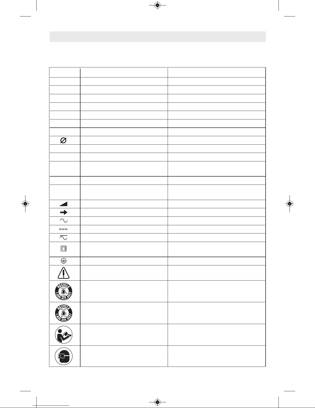
IMPORTANT: Some of the following symbols may be used on your tool. Please study them
and learn their meaning. Proper interpretation of these symbols will allow you to operate the
tool better and safer.
Symbol Name Designation/Explanation
V Volts Voltage (potential)
A Amperes Current
Hz Hertz Frequency (cycles per second)
W Watt Power
kg Kilograms Weight
min Minutes Time
s Seconds Time
Diameter Size of drill bits, grinding wheels, etc.
n
0
No load speed Rotational speed, at no load
n Rated speed Maximum attainable speed
.../min Revolutions or reciprocation Revolutions, strokes, surface speed,
per minute orbits etc. per minute
0 Off position Zero speed, zero torque...
1, 2, 3, ... Selector settings Speed, torque or position settings.
I, II, III, Higher number means greater speed
Infinitely variable selector with off Speed is increasing from 0 setting
Arrow Action in the direction of arrow
Alternating current Type or a characteristic of current
Direct current Type or a characteristic of current
Alternating or direct current Type or a characteristic of current
Class II construction Designates Double Insulated
Construction tools.
Earthing terminal Grounding terminal
Warning symbol Alerts user to warning messages
Li-ion RBRC seal Designates Li-ion battery recycling
program
Ni-Cad RBRC seal Designates Ni-Cad battery recycling
program
Read manual symbol Alerts user to read manual
Wear eye protection symbol Alerts user to wear eye protection
Symbols
0
BM 2610033457 06-14_JS120 6/5/14 12:02 PM Page 5
Page 6

-6-
This symbol designates that this tool is listed by Underwriters Laboratories.
This symbol designates that this tool is listed by the Canadian Standards
Association.
This symbol designates that this tool is listed by the Canadian Standards
Association, to United States and Canadian Standards.
This symbol designates that this tool complies to NOM Mexican Standards.
This symbol designates that this tool is listed by the Intertek Testing
Services, to United States and Canadian Standards.
Symbols (continued)
IMPORTANT: Some of the following symbols may be used on your tool. Please study them
and learn their meaning. Proper interpretation of these symbols will allow you to operate the
tool better and safer.
This symbol designates that this component is recognized by Underwriters
Laboratories.
This symbol designates that this tool is listed by Underwriters Laboratories,
to United States and Canadian Standards.
BM 2610033457 06-14_JS120 6/5/14 12:02 PM Page 6
Page 7
Model number . . . . . . . . . . . . . . JS120
Maximum Capacities
Stroke length . . . . . . . . . . . . . . . . . 3/4" (18 mm)
Wood . . . . . . . . . . . . . . . . . . . . . . . . . . 2-1/2" (70 mm)
Aluminium . . . . . . . . . . . . . . . . . . . . 1/8" (3 mm)
Mild steel . . . . . . . . . . . . . . . . . . . . . . 1/8" (3 mm)
-7-
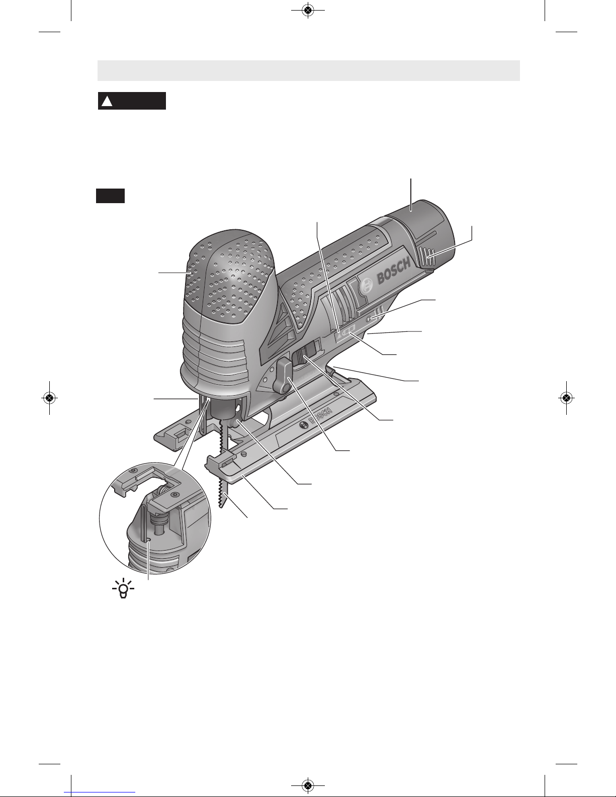
Functional Description and Specifications
Disconnect battery pack from tool or place the switch in the locked or
off position before making any assembly, adjustments or changing
accessories. Such preventive safety mea sures reduce the risk o f starting the tool
accidentally.
!
WARNING
Cordless Jig Saw
SLIDE ON-OFF SWITCH
BLADE ORBIT SELECTOR LEVER
BLADE
GUIDE ROLLER
FOOTPLATE
FINGER
GUARD
BATTERY
PACK
RELEASE
TABS
BATTERY PACK
ALLEN WRENCH
& STORAGE AREA
BATTERY CHARGE
INDICATOR
TEMPERATURE
OVERLOAD PROECTION
INDICATOR
FIG. 1
Battery Packs/Chargers
Please refer to the Charger Manual included with your tool.
NOTE: For tool specifications refer to the nameplate on your tool.
LED
RUBBERIZED
GRIP
LED WORKLIGHT
ON/OFF SWITCH
VARIABLE SPEED DIAL
BM 2610033457 06-14_JS120 6/5/14 12:02 PM Page 7
Page 8

BLADE INSTALLATION AND REMOVAL
To prevent damage, do not
turn blade ejector lever when
there is no blade in the blade clamp or when
inserting the blade.
BLADE INSTALLATION
Insert the saw blade (teeth in cutting direction)
into the slot in the blade clamp until the blade
ejector lever rotates to the LEFT, indicating that
the clamp has engaged. (When inserting the
saw blade, the back of the blade must rest in
the groove of the guide roller Fig. 2.)
BLADE EJECTION
The tool should be held so that the blade is
safely ejected. To remove the saw blade, rotate
the blade ejector lever to the RIGHT to the
center stop; this releases and ejects the saw
blade (Fig. 3).
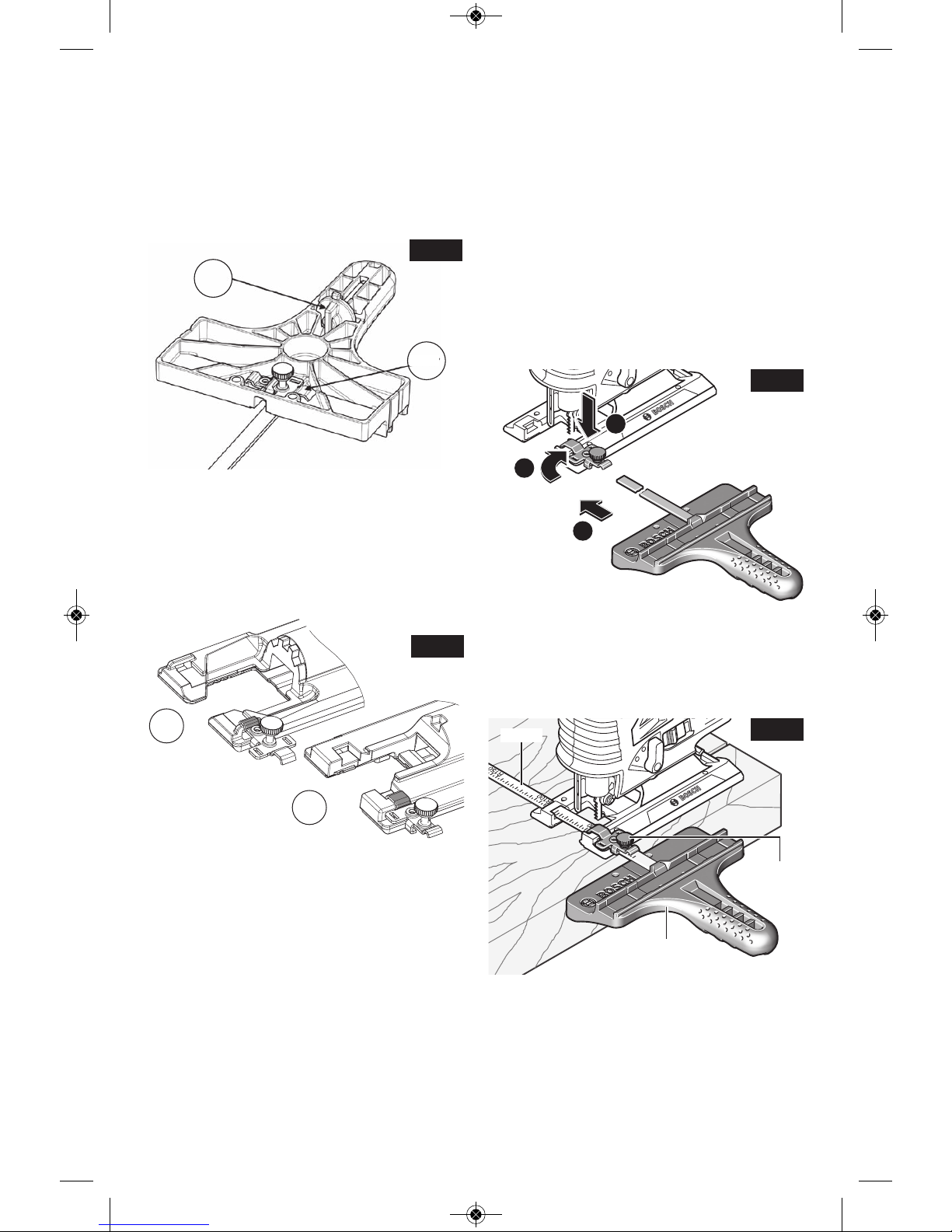
BLADE CLAMP RESET – There are two
situations in which it is necessary to reset
the blade clamp:
RESET Type A: If the blade ejection lever is
rotated improperly, the “fingers” within the
clamp may slip into the blade insert slot. To
reset the clamp:
Step 1 – Using a a screwdriver, push down on
blade clamp fingers (as viewed from the bottom
of the jig saw), until clamp can be rotated.
Step 2 – Rotate blade ejector lever to the
RIGHT until it locks into place.
The clamp is now ready for use.
RESET Type B: If the two fingers inside the
blade clamp accidentally get pushed too far into
the plunger, they will prevent insertion of a
blade. To bring the fingers bac k to their
correction positions:
Step 1 – Turn the blade ejector lever to the
RIGHT (as viewed from the bottom of the jig
saw)
Step 2 – Continue the rotation unto fingers will
snap into the correct open position.
The clamp is now ready for use.
-8-
Assembly
!
CAUTION
FIG. 2
FIG. 3
BLADE
CLAMP
LEVER
BLADE
CLAMP
LEVER
FINGERS
BLADE CLAMP IN OPEN POSITION
(As viewed from the bottom)
BLADE CLAMP IN LOCKED POSITION
(As viewed from the bottom)
BLADE
BLADE
BLADE
Disconnect battery pack from tool or place the switch in the locked or
off position before making any assembly, adjustments or changing
accessories. Such preventive safety mea sures reduce the risk o f starting the tool
accidentally.
!
WARNING
BM 2610033457 06-14_JS120 6/5/14 12:02 PM Page 8
Page 9
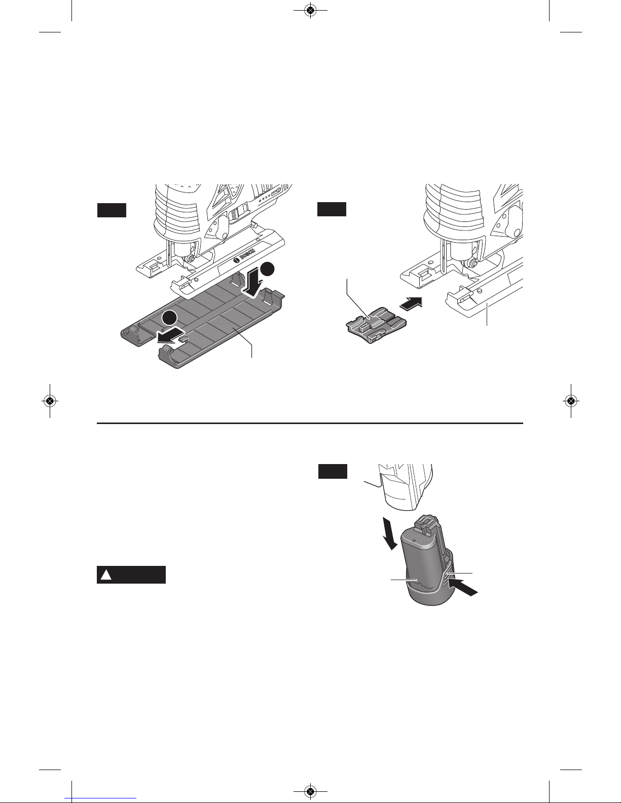
ATTACHING NON-MARRING
OVERSHOE
Your tool is equipped with a protective plastic
overshoe that protects finer surfaces.
To attach, hook overshoe over front of metal
fo otplate and snap int o place at rea r of
footplate (Fig. 4).
ANTI-SPLINTER INSERT
To minimize splintering of the top surface of
the material being cut, place the anti-splinter
insert in the blade opening of the footplate, or
the non-marring overshoe (Fig. 5).
Note: This insert will only work with blades
that have ground sides such as T301CD,
TB1B, T101D, and T101DP.
-9-
1
2
FIG. 4
FIG. 5
NON-MARRING
OVERSHOE
ANTI-SPLINTER
INSERT
FOOTPLATE
INSERTING AND RELEASING
BATTERY PACK
Release battery pack from tool by pressing
on both sides of the battery release tabs and
pull downward (Fig. 6).
To insert battery, align battery and slide
battery pack into tool until it locks into position.
Do not force.
If battery release tabs are
cracked or othe rwi se
damaged, do not insert into tool. Battery
can fall out during operation.
!
WARNING
FIG. 6
RELEASE
TABS
BATTERY
PACK
BM 2610033457 06-14_JS120 6/5/14 12:02 PM Page 9
Page 10
-10-
SLIDE ON-OFF SWITCH
The tool is switched “ON” by the switch button
located at the side of the motor housing. The
switch locks in the “ON” posit ion , a
convenience for continuous operation (Fig. 1).
TO TURN THE TOOL “ON” slide the switch
button forward.
TO UNLOCK THE SWITCH, slide the switch
button backward.
BRAKE
When the trigger is released it activates the
electrical brake to stop the blade quickly. This
feature is especially useful when making
repetitive cuts.
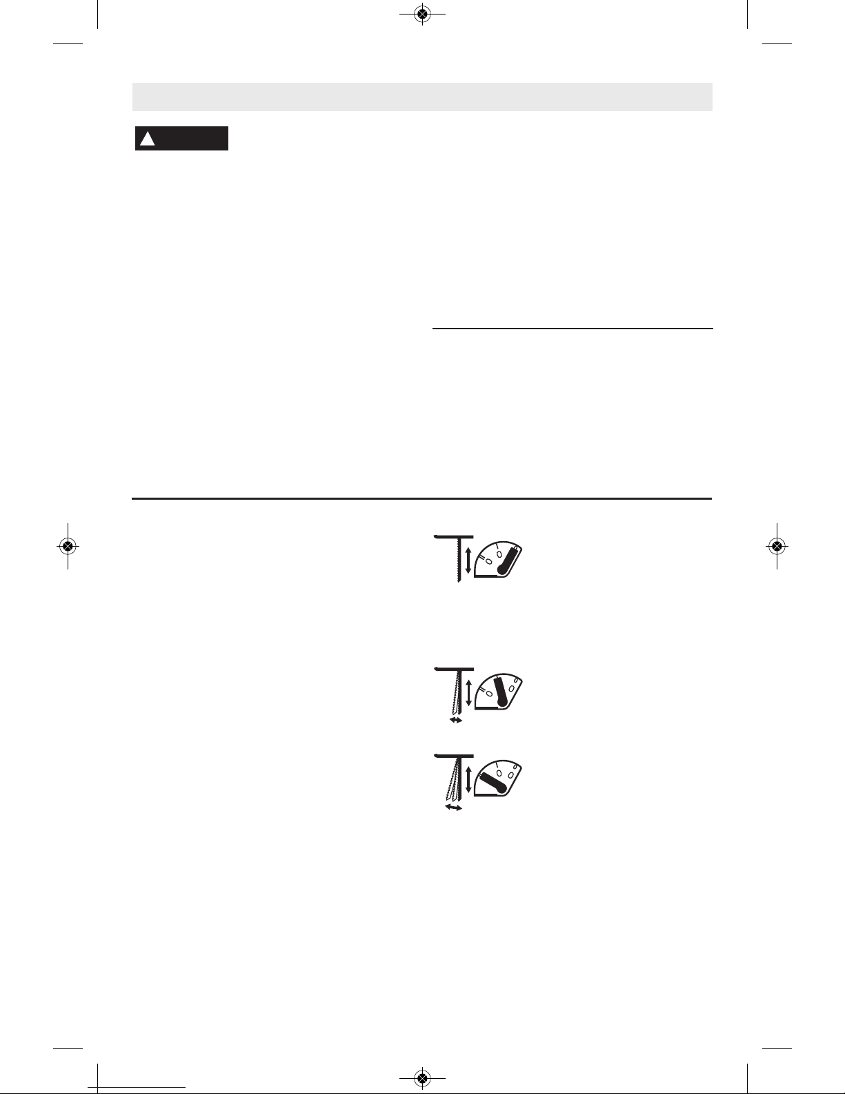
BLADE ORBIT SELECTOR LEVER
Maximum cutting efficiency can be obtained
by adjusting the blade orbit selector lever to
suit the material being cut.
The following chart will help you determine
which setting to use for your application. This
chart is intended as a guideline only, and test
cuts in scrap material should be performed
first to determine the best setting.
Setting O
Hard mater i als s uch a s
metals or thin sheet metals.
This setting can be used with
knif e blades, g rit edg e
blades, rasp work. and down
cutting blades.
Setting 1
Soft materials where cleaner
cutting or delicate scrolling
work is performed.
Setting 2
Med ium den sity mat eria ls
such as harde r woods or
particle board. Soft materials
such as wood, plastics, etc.
and when fast cutting is more
important than a clean cut.
WORK LIGHT
Your tool is equipped with a work light for better
visibility during operation. Once the tool has
been turned on, the light can be turned on by
pressing the LED switch. When the tool is
switched off, the light turns off. (Fig 1)
Operating Instructions
PLUNGER SPEED
The jigs aw cut ting spee d or str oke ra te
required depends on the material being cut,
the type of blade being used, and the feed rate
preferred by the operator.
The best speed for a particular application is
largely determined by experience though as a
general rule, slower speeds are for denser
materials and faster speeds for softer materials.
Note: that when the jigsaw is used at low
speed settings for an extended length of time,
the motor temperature will rise due to slower
speeds of the internal cooling fan. In such
cases, it is necessary to occasionally run the
tool at full speed for a few minutes to keep the
motor running at high efficiency.
VARIABLE SPEED DIAL
Your Jigsaw is equipped with a variable speed
dial. The blade stroke rate may be adjusted
during cutting operation by presetting the dial
on or between any one of the six numbers.
SPM rating
Setting (strokes per minute)
1 1500
2 1800
3 2050
4 2300
5 2550
6 2800
Disconnect battery pack from tool or place the switch in the locked or
off position before making any assembly, adjustments or changing
accessories. Such preventive safety mea sures reduce the risk o f starting the tool
accidentally.
!
WARNING
BM 2610033457 06-14_JS120 6/5/14 12:02 PM Page 10
Page 11
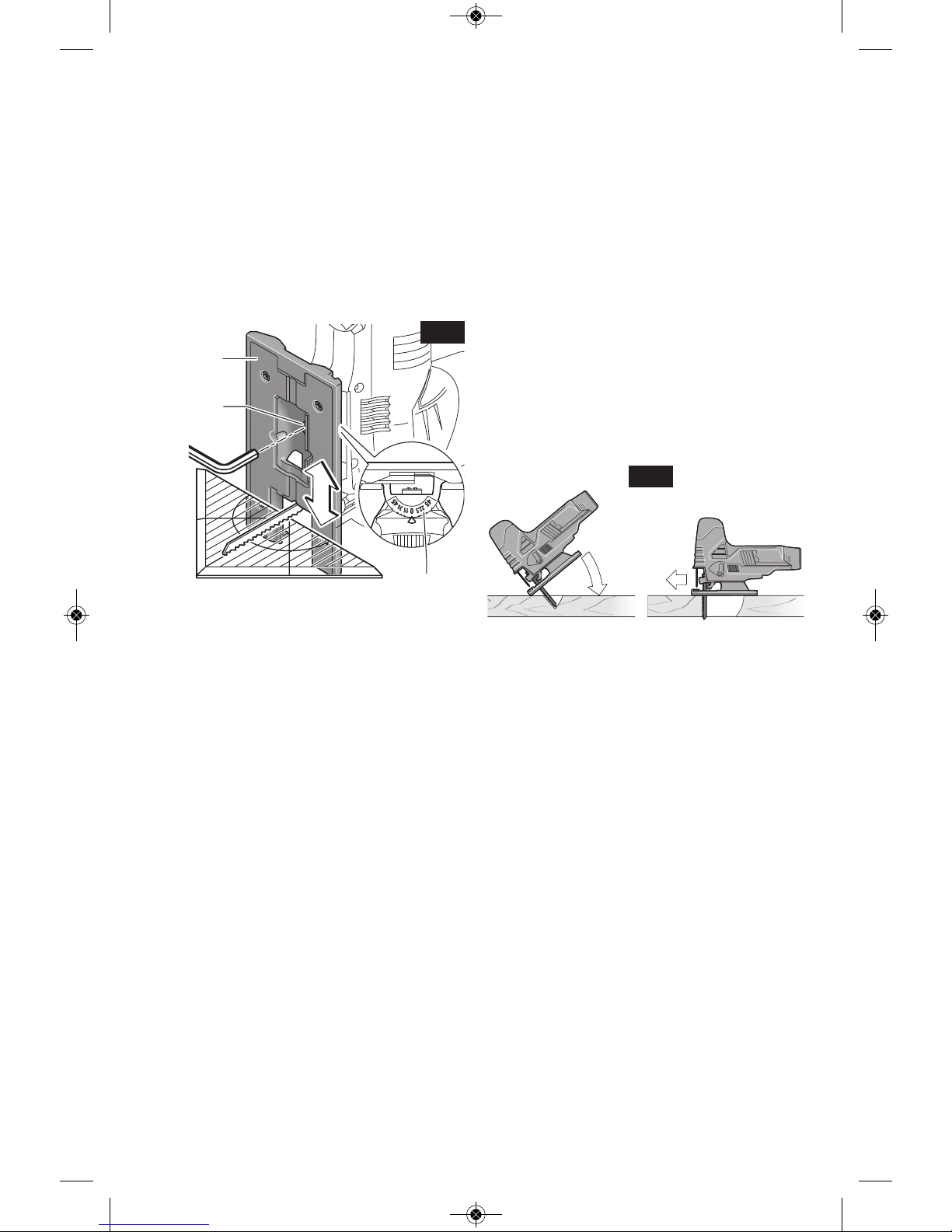
FOOTPLATE ANGLE ADJUSTMENT
The footplate may be tilted to allow angle cuts
up to 45° in either direction (Fig. 7).
Note: before adjusting the footplate, remove
anti-splinter insert if used.
Open the lock lever to unlock footplate. Push
and hold the footplate firmly towards the back
of tool as shown. While holding the footplate
backwards tilt footplate to desired angle on
bevel scale, then release pressure on footplate
so it engages into detent at desired angle (Fig. 7).
Your tool has detent slots the footplate will
engage at 0° & 45°, and there are additional
position marks for 15°, 22.5° and 30° angles.
Close the lock lever slowly to assure that
footplate is locked at the desired angle.
TOOL TIPS
Always be certain that smaller workpieces
are securely fastened to a bench or other
support. Larger panels may be held in place
by clamps on a bench or sawhorses.
To begin a cut, clearly mark the cutting line,
and rest the front of the footplate on the work.
Engage the switch, and move the blade into
the work using only enough forward pressure
to keep the blade cutting steadily. Do not
force, as this will not make the saw cut faster;
let the blade do the work.
Choose blades carefully, as the ability of the
jig saw to follow curves, provide smoother
finishes, or faster cutting is directly related to
the type of blade used (See your Bosch Dealer).
For tight curves it is best to use a narrow or
scroll blade.
When sawing metal or similar materials, apply
coolant/lubricant alongside the cutting line.
Use of reverse-tooth blade such as the Bosch
T101BR requires the orbital setting to be “0”
and that downward pressure be applied to the
top of the saw.
PLUNGE CUTTING
Plunge cutting is useful and time-saving in
making rough openings in softer materials. It
is not necessary to drill a hole for an inside or
pocket cut. The longest blade to be used for
plunge cutting is 3-1/8" (80 mm). Footplate
must be set 0° setting.
Draw lines for the opening, hold the saw
firmly, tilt it forward so that the toe of the saw
foot rests on the work, but with the blade well
clear of the work. Turn the tool on and run at
top speed, and then very gradually lower the
blade (Fig. 8).
When it touches, continue pressing down on
the toe of the saw foot slowly pivoting the saw
like a hinge until the blade cuts through and
the foot rests flat on the work. Then saw
ahe ad on t he cut ting line. We do n ot
recommend plunge cutting with a scroll blade.
Do not try to plunge cut into hard materials
such as steel.
To make sharp corners, cut up to the corner,
then back up slightly before rounding the
corner. After the opening is complete, go back
to each corner and cut it from the opposite
direction to square it off.
-11-
FOOTPLATE
SCREW
FIG. 7
BEVEL
SCALE
FOOTPLATE
FIG. 8
BM 2610033457 06-14_JS120 6/5/14 12:02 PM Page 11
Page 12

-12-
TEMPERATURE-DEPENDENT
OVERLOAD PROTECTION
In normal conditions of use, the tool cannot
be overloaded. However, if the power tool is
overloaded or not kept within the permitted
battery temperature rang e, the speed is
reduced or the power tool switches off. If the
tool speed is automatically reduced in such
situations, the tool will run again at full speed
once the permitted battery temperature is
rea ched or the lo ad is redu ced. Dur ing
automatic shut-down, switch off the power
tool, allow the battery to cool down, and then
switch the power tool back on. (Fig. 1)
TEMPERATURE-DEPENDENT OVERLOAD
PROTECTION INDICATOR
The red L E D indi c ator w ill h elp y o u in
protecting the battery against overheating
and the motor against overloading. (Fig. 1)
When the LED indicator continuously lights
up red, it means that the temperature of the
battery is too high and the tool switches off
automatically.
– Switch the power tool off.
– Allow the battery to cool down before
continuing to work.
When the LED indicator flashes red, it means
the tool is plunger mechanism has been
sto p ped by t he w orkpi e ce a nd t he tool
switches off automatically.
– Remove the tool from the workpiece.
– As soon as the plunger mechanism has
been freed, the tool will continue to work at
the set stroke rate.
RESTART PROTECTION
The res tart pro tect ion feat ure prev ents
uncontrolled starting of the machine after a
power failure. Once the restart protection
feature is active, the temperature overload
pr otection indicator blinks c ontinuously .
(Fig. 1)
To restart the operation, switch the On/Off
switch to the Off position and start the tool
again.
Note: When switching off and on again very
qu ickly, it is possi ble that the restarting
protection will be triggered; this will prevent
the power tool from starting, even though the
On/Off switch is actuated. Set the On/Off
switch to the off position, and then switch the
tool on again.
PROTECTION AGAINST DEEP
DISCHARGING
The lithium ion battery is protected against
deep discharging by the “Electronic Cell
Pro tect ion (ECP )”. When th e b atter y i s
empty, the machine is switched off by means
of a protective circuit: The inserted tool no
longer rotates.
BATTERY CHARGE-CONTROL
INDICATION
The three green LEDs of the battery chargecontrol indicator show the charging status of
th e battery. (Fi g. 1) The batt ery ch arg e
cont r ol ind i c ator o nly i l luminat e s for 5
seconds after start-up.
LED Capacity
Continuous lighting 3 x green 2/3
Continuous lighting 2 x green 1/3
Continuous lighting 1 x green <1/3
Flashing light 1 x green Reserve
Flashing light 3 x green Empty
When no LED lights up after switching on,
then the battery is defective and must be
replaced.
BM 2610033457 06-14_JS120 6/5/14 12:02 PM Page 12
Page 13
-13-
JA1010 CIRCLE AND PARALLEL
CUTTING GUIDE
The JA1010 is used for fast and accurate
straight and circle cutting. It includes the
guide, two clamps for attaching it to the jig
saw (A), and a center pin for guiding circle
cuts (B). The clamps and the centering pin
can be stored on the guide (Fig. 9).
One end of the clamp is used to attach the
guide’s bar to jig saws that have narrow tops
on their footplate mounting slots (C) and the
other end is used to attach the guide’s bar to
jig saws that have wide tops on their footplate
mounting slots (D) (Fig. 10).
When possible, attach the bar to the jig saw
using both clamps for enhanced grip and
precision.
ATTACHING GUIDE TO JIG SAW
1. Orient the blade clamp so that the proper
end is placed on the jig saw foot from
either side of the tool.
2. Insert guide bar through a clamp, then
through the slots provided in foot, with the
guide’s fence orientated correctly for the
intended application, parallel cutting or
circle cutting. (If possible, place second
clamp on bar from opposite side of jig
saw.)
3. Pla ce lock knob(s) o n proper side of
clamp(s) and securely tighten lock knob(s)
on the clamp(s) (Fig. 11).
PARALLEL CUTTING
Parallel cuts can be made from 5/8” to 6” in
from the edge of the workpiece.
1. The guide fence surface needs to be
positioned ALONGSIDE the workpiece
(Fig. 12).
2. Hook clamp(s) onto footplate, adjust fence
to desired width and place lock knob(s) on
proper side of clamp(s)
3. Securely tighten lo ck knob(s) on th e
clamp(s) (Fig. 11).
4. Insert jig saw plug into power source, hold
the saw firmly, squeeze trigger and slowly
push the saw forward (Fig. 12).
A
B
D
C
1
3
2
FIG. 9
FIG. 10
FIG. 11
FIG. 12
BAR
LOCK KNOB
CLAMP
EDGE GUIDE
DOWN
BM 2610033457 06-14_JS120 6/5/14 12:02 PM Page 13
Page 14
-14-
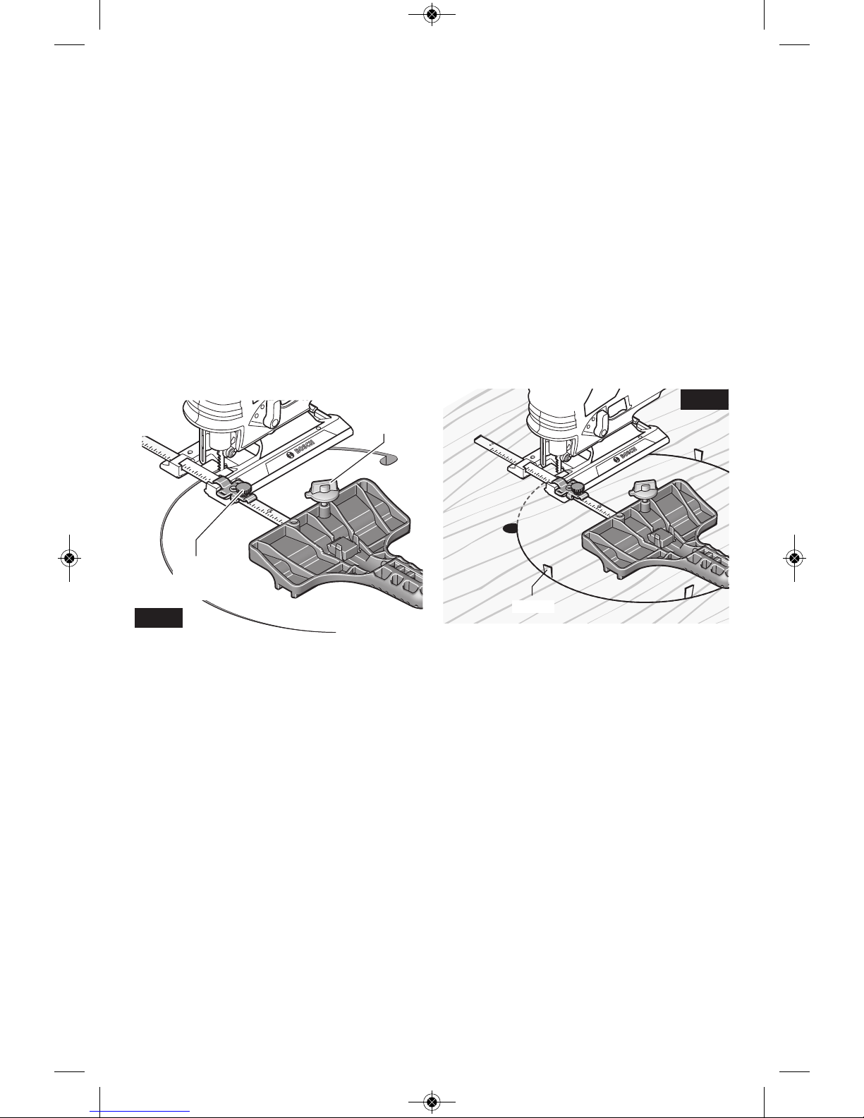
CIRCLE CUTTING
Circle cuts can be made from 5” to 16-1/2” in
diameter
1. Determine the center point of the desired
circle.
2. Drill a 3/16” (5 mm) center hole 7/8” (23
mm) deep in workpiece. (For enhanced
precision, drill the hole using a drill press, if
possible).
3. Drill or plunge cut near the circle’s edge,
turn saw off, and disconnect the plug from
power source.
4. Insert guide bar through a clamp, then
through the slots provided in foot, from
either side of foot (Fig. 13). (If possible,
place second clamp on bar from opposite
side of jig saw).
5. Remove guide pin from end of guide, push
pin through proper hole provided in guide,
then into center hole of workpiece. (When
used with a Bosch JS572 jig saw --- or the
JS180 cordless jig saw --- the holes labeled
for the JS572 should be used.) For other jig
saws, one of the other holes should be
used.
6. Measure the distance from the center of the
hole to the desired circle radius. Adjust that
measurement as necessary to account for
the width of the blade:
- When cutting a hole, cut from inside the
intended radius.
- When cutting wheels or discs, cut from the
outside the intended radius.
7. Hook clamp(s) onto footplate, and position
the guide to that a dju sted radius
measurement.
8. Place lo ck kno b(s) o n proper sid e of
clamp(s) and securely tighten lock knob(s)
on the clamp(s) (Fig. 11).
9. Insert jig saw plug into power source, hold
the saw firmly, squeeze trigger and slowly
push the saw forward.
CIRCLE-CUTTING TIPS:
• Place small wedges in the cut as shown in
Fi g. 14, to ke ep th e inn er circle fro m
spreading when near the end of the cut.
• Use a thick jig saw blade, such as the
Bosch T101TP or T144DP wheneve r
possible.
• Make sure that the jig saw orbital setting is
at 0 (zero)
• Cut slowly so the blade will stay straight in
the cut.
FIG. 13
FIG. 14
GUIDE
PIN
LOCK
KNOB
CLAMP
WEDGE
BM 2610033457 06-14_JS120 6/5/14 12:02 PM Page 14
Page 15

Accessories
Maintenance
-15-
Service
NO USER SERVICE-ABLE
PARTS INSIDE. Preventive
maintenance performed by un au thorized
personnel may result in misplacing of
internal wires and components which
could cause serious hazard. We recom -
mend that all tool service be performed by a
Bosch Factory Service Center or Authorized
Bos c h S ervic e Sta tion. SERV ICE MEN:
Disconnect tool and/or charger from power
source before servicing.
BATTERIES
Be alert for battery packs that are nearing
their end of life. If you notice decreased
tool performance or significantly shorter
running time between charges then it is time
to replace the battery pack. Failure to do so
can cause the tool to operate improperly or
damage the charger.
TOOL LUBRICATION
Your Bosch tool has been properly lubricated
and is ready for use.
CARBON BRUSHES
The brushes and commutator in your tool
have been engineered for many hours of
dep endable se rvic e. To mai ntai n peak
efficiency of the motor, we recommend every
two to six months the brush es be examined.
Only genuine Bosch replace ment brushes
specially designed for your tool should be
used.
BEARINGS
Bearings which become noisy (due to heavy
load or very abrasive material cut ting) should
be replaced at once to avoid overheating or
motor failure.
D.C. MOTORS
The motor in your tool has been engineered
for many hours of dependable service. To
maintain peak efficiency of the motor, we
reco m mend it b e examin e d every s i x
months. Only a genuine Bosch replacement
motor specially designed for your tool should
be used.
Cleaning
To avoid accidents, always
disconnect the tool and/or
charger from the power supply before
cleaning. The tool may be cleaned most
effectively with com pressed dry air. Always
wear safety goggles when cleaning tools
with compressed air.
Ventilation openings and switch levers must
be kept clean and free of foreign matter. Do
not attempt to clean by inserting pointed
objects through opening.
Ce rtain cleaning agents
and sol vents da mage
plastic parts. Some of these are: gasoline,
car bon tetrachloride, chlorinated cleaning
solvents, ammonia and household detergents
that contain ammonia.
CLEANING BLADE HOLDER
Clean the saw blade holder regularly. For this,
remove the saw blade from the tool and lightly
tap footplate on a level surface.
Regularly spray penetrating oil onto the saw
blade holder.
Check the guide roller regularly. If worn, it
must be replaced through an authorized
Bosch Factory Service Center
Lubricate the guide roller occasionally with a
drop of oil.
!
WARNING
!
WARNING
!
CAUTION
* Non-marring overshoe
* Anti splinter insert
* T-shank jig saw blade
** Circle and parallel cutting guide
** Carrying case
** Other T-shank jig saw blades
(*= standard equipment)
(**= optional accessories)
The use of any other acces so ries not specified in this manual may create a hazard.
!
WARNING
BM 2610033457 06-14_JS120 6/5/14 12:02 PM Page 15
Page 16

-16-
Veuillez lire tous les avertissements et toutes les consignes de sécurité. Si l'on
n'observe pas ces avertissements et ces consignes de sécurité, il existe un risque de
choc électrique, d'incendie et/ou de blessures corporelles graves.
CONSERVEZ TOUS LES AVERTISSEMENTS ET TOUTES LES CONSIGNES
DE SÉCURITÉ POUR RÉFÉRENCE FUTURE.
Dans les avertissements, le terme « outil électroportatif » se rapporte à votre outil branché sur le secteur (avec fil)
ou à votre outil alimenté par piles (sans fil).
Avertissements généraux concernant la sécurité des outils électroportatifs
AVERTISSEMENT
!
Sécurité du lieu de travail
Maintenez le lieu de travail propre et bien éclairé.
Les risques d’accident sont plus élevés quand on
travaille dans un endroit encombré ou sombre.
N’utilisez pas d’outils électroportatifs dans des
atmosphères explosives, comme par exemple en
présence de gaz, de poussières ou de liquides
inflammables. Les outils électroportatifs produisent
des étincelles qui risquent d’enflammer les poussières
ou les vapeurs.
Éloignez les enfants et les visiteurs quand vous vous
servez d’un outil électroportatif. Vous risquez une
perte de contrôle si on vous distrait.
Sécurité électrique
Les fiches des outils électroportatifs doivent
correspondre à la prise. Il ne faut absolument jamais
modifier la fiche. N’utilisez pas d’adaptateur de prise
avec des outils électroportatifs munis d’une fiche de
terre. Le risque de choc électrique est moindre si on
utilise une fiche non modifiée sur une prise qui lui
correspond.
Évitez tout contact du corps avec des surfaces reliées
à la terre tels que tuyaux, radiateurs, gazinières ou
réfrigérateurs. Le risque de choc électrique augmente
si votre corps est relié à la terre.
N’exposez pas les outils électroportatifs à la pluie ou
à l’humidité. Si de l’eau pénètre dans un outil
électroportatif, le risque de choc électrique augmente.
Ne maltraitez pas le cordon. Ne vous en servez
jamais pour transporter l’outil électroportatif, pour le
tirer ou pour le débrancher. Éloignez le cordon de la
chaleur, des huiles, des arêtes coupantes ou des
pièces mobiles. Les cordons abîmés ou emmêlés
augmentent les risques de choc électrique.
Si vous utilisez un outil électroportatif à l’extérieur,
employez une rallonge conçue pour l’extérieur. Ces
rallonges sont faites pour l’extérieur et réduisent le
risque de choc électrique.
S'il est absolument nécessaire d'utiliser l'outil
électroportatif dans un endroit humide, utilisez une
alimentation protégée par un disjoncteur de fuite de
terre (GFCI). L'utilisation d'un disjoncteur GFCI réduit
les risques de choc électrique.
Sécurité personnelle
Restez concentré, faites attention à ce que vous
faites, et servez-vous de votre bon sens lorsque vous
utilisez un outil électroportatif. N'employez pas
d’outils électroportatifs quand vous êtes fatigué ou
sous l’emprise de drogues, d’alcool ou de
médicaments. Quand on utilise des outils
électroportatifs, il suffit d’un moment d’inattention pour
causer des blessures corporelles graves.
Utilisez des équipements de sécurité personnelle.
Portez toujours une protection oculaire. Le port
d'équipements de sécurité tels que des masques
antipoussières, des chaussures de sécurité
antidérapantes, des casques de chantier et des
protecteurs d'oreilles dans des conditions appropriées
réduira le risque de blessure corporelle.
Évitez les démarrages intempestifs. Assurez-vous que
l'interrupteur est dans la position arrêt (Off) avant de
brancher l'outil dans une prise de courant et/ou un
bloc-piles, de le ramasser ou de le transporter. Le
transport d'un outil électroportatif avec le doigt sur la
gâchette ou le branchement de cet outil quand
l'interrupteur est en position de marche (ON) est une
invite aux accidents.
Enlevez toutes les clés de réglage avant de mettre
l’outil électroportatif en marche. Si on laisse une clé
sur une pièce tournante de l’outil électroportatif, il y a
risque de blessure corporelle.
Ne vous penchez pas. Conservez toujours une bonne
assise et un bon équilibre. Ceci vous permettra de
mieux maîtriser l’outil électroportatif dans des situations
inattendues.
Habillez-vous de manière appropriée. Ne portez pas
de vêtements amples ou de bijoux. Attachez les
cheveux longs. N’approchez pas les cheveux, les
vêtements ou les gants des pièces en mouvement.
Les vêtements amples, les bijoux ou les cheveux longs
risquent d’être happés par les pièces en mouvement.
Si l’outil est muni de dispositifs permettant le
raccordement d’un système d’aspiration et de
collecte des poussières, assurez-vous que ces
dispositifs sont raccordés et utilisés correctement.
L'utilisation d'un dépoussiéreur peut réduire les
dangers associés à l'accumulation de poussière.
BM 2610033457 06-14_JS120 6/5/14 12:02 PM Page 16
Page 17

Tenez l’outil électroportatif par ses surfaces de
préhension isolées lorsque vous effectuez une
opération à l’occasion de laquelle l’accessoire de
coupe risque d’entrer en contact avec un fil caché.
Tout contact de l’accessoire de coupe avec un fil sous
tension risque de mettre aussi sous tension les
parties métalliques exposées de l’outil électroportatif,
ce qui pourrait causer un choc électrique pour
l’opérateur.
Utilisez des brides ou d’autres moyens pratiques de
brider ou de supporter la pièce sur une plate-forme
stable. Tenir la pièce à la main ou contre le corps est
instable et risque de résulter en une perte de contrôle.
Ne percez, fixez et ne rentrez pas dans des murs
existants ou autres endroits aveugles pouvant
abriter des fils électriques. Si cette situation est
inévitable, débranchez tous les fusibles ou les
disjoncteurs alimentant ce site.
Débranchez le bloc-pile de l'outil ou placez
l'interrupteur à la position de blocage ou d'arrêt
avant d'effectuer tout assemblage ou réglage ou de
changer les accessoires. Ces mesures de sécurité
préventives réduisent le risque d'une mise en marche
accidentelle de l'outil.
Ne tenez jamais la gâchette bloquée en position de
marche. Avant d’insérer le bloc-pile, vérifiez que le
blocage de gâchette est en position « arrêt » (OFF).
Les mises en marche accidentelles peuvent causer
des blessures.
Gardez les mains à l'écart de la zone de coupe. Ne
placez surtout pas la main sous le matériau que
vous coupez. Il est impossible de déterminer
exactement la proximité de la lame de votre main.
Règles de sécurité concernant les scies sauteuses
-17-
Utilisation et entretien des outils
électroportatifs
Ne forcez pas sur l’outil électroportatif. Utilisez l’outil
électroportatif qui convient à la tâche à effectuer.
L’outil qui convient à la tâche fait un meilleur travail et
est plus sûr à la vitesse pour lequel il a été conçu.
Ne vous servez pas de l’outil électroportatif si son
interrupteur ne parvient pas à le mettre en marche ou
à l’arrêter. Tout outil électroportatif qui ne peut pas
être commandé par son interrupteur est dangereux et
doit être réparé.
Débranchez la fiche de la prise ou enlevez le bloc-pile
de l’outil électroportatif avant tout réglage,
changement d’accessoires ou avant de ranger l’outil
électroportatif. De telles mesures de sécurité
préventive réduisent le risque de démarrage intempestif
de l’outil électroportatif.
Rangez les outils électroportatifs dont vous ne vous
servez pas hors de portée des enfants et ne permettez
pas à des personnes qui ne connaissent pas l’outil
électroportatif ou qui ignorent ces consignes de s’en
servir. Les outils électroportatifs sont dangereux dans
les mains d’utilisateurs inexpérimentés.
Entretenez les outils électroportatifs. Vérifiez que les
pièces mobiles sont alignées correctement et ne
coincent pas. Vérifiez qu’il n’y a pas de pièces
cassées ou d’autre circonstance qui risquent
d’affecter le fonctionnement de l’outil électroportatif.
Si l’outil est abîmé, faites-le réparer avant de
l’utiliser. De nombreux accidents sont causés par des
outils électroportatifs mal entretenus.
Maintenez les outils coupants affûtés et propres. Les
outils coupants entretenus correctement et dotés de
bords tranchants affûtés sont moins susceptibles de
coincer et sont plus faciles à maîtriser.
Utilisez l'outil électroportatif, les accessoires et les
embouts d'outil, etc. conformément à ces
instructions, en tenant compte des conditions de
travail et des travaux à réaliser. L'emploi d’outils
électroportatifs pour des tâches différentes de celles
pour lesquelles ils ont été prévus peut résulter en une
situation dangereuse.
Utilisation et entretien des outils à piles
Rechargez les piles uniquement avec le chargeur
spécifié par le fabriquant. Un chargeur qui convient à
un type de bloc-piles peut entraîner un risque d’incendie
quand il est utilisé avec un autre bloc-piles.
Utilisez des outils électroportatifs uniquement avec
les bloc-piles spécifiquement désignés pour eux.
L’utilisation de tout autre bloc-piles peut créer un risque
de blessures et d’incendie.
Lorsque le bloc-piles n’est pas utilisé, gardez-le à
distances d’autres objets métalliques tels que des
trombones, des pièces de monnaie, des clés, des
clous, des vis ou de tout autre objet métallique
pouvant faire une connexion entre une borne et une
autre. Court-circuiter les bornes des piles peut causer
des brûlures ou un incendie.
Dans des conditions abusives, du liquide peut être
éjecté de la pile ; dans un tel cas, évitez tout contact
avec ce liquide. Si un contact se produit
accidentellement, rincez avec de l’eau. Si le liquide
entre en contact avec les yeux, consultez un médecin.
Du liquide éjecté de la pile peut causer des irritations ou
des brûlures.
Entretien
Faites réparer votre outil électroportatif par un agent
de service qualifié n’utilisant que des pièces de
rechange identiques. Ceci assure que la sécurité de
l’outil électroportatif est préservée.
BM 2610033457 06-14_JS120 6/5/14 12:02 PM Page 17
Page 18

-18-
Évitez de vous placer les mains entre le carter
d'engrenages et le porte-lame de la scie. Le porte-
lame à mouvement alternatif risquerait de vous pincer
les doigts.
N'utilisez pas de lames émoussées ou
endommagées. Les lames pliées peuvent aisément
se fracturer ou causer un rebond.
Avant de commencer à couper, mettez l'outil en
marche et attendez que la lame atteigne sa vitesse
maximale. L'outil peut trembler ou vibrer si la vitesse
de la lame est trop lente au début de la coupe, et il
peut éventuellement rebondir.
Il importe de bien assujettir la pièce sur laquelle
vous travaillez. Ne la tenez jamais dans votre main
ou sur vos jambes. Les pièces minces et plus petites
peuvent fléchir ou vibrer avec la lame, risquant ainsi
de vous faire perdre le contrôle.
Avant de commencer à scier, assurez-vous que
toutes les vis de réglage et que le porte-lame sont
serrés. Les vis de réglage et porte-lame lâches
peuvent faire glisser l'outil ou la lame et ainsi vous
faire perdre le contrôle.
En retirant la lame de l'outil, évitez le contact avec
la peau et utilisez des gants protecteurs appropriés
en saisissant la lame ou l'accessoire. Les
accessoires peuvent être chauds après un usage
prolongé.
Avertissements supplémentaires concernant la sécurité
L’emploi d’un GFCI et de dispositifs de protection
personnelle tels que gants et chaussures d’électricien en
caoutchouc améliorent votre sécurité personnelle.
N’utilisez pas un outil conçu uniquement pour le C.A.
sur une alimentation en C.C. Même si l’outil semble
fonctionner, les composants électriques d’un outil prévu
pour le C.A. tomberont probablement en panne et
risquent de créer un danger pour l’utilisateur.
Maintenez les poignées sèches et exemptes d’huile et
de graisse. On ne pas maîtriser un outil électroportatif
en toute sécurité quand on a les mains glissantes.
Créez un agenda d’entretien périodique pour votre
outil. Quand vous nettoyez un outil, faites attention
de n’en démonter aucune pièce car il est toujours
possible de mal remonter ou de pincer les fils
internes ou de remonter incorrectement les ressorts
de rappel des capots de protection. Certains agents de
nettoyage tels que l’essence, le tétrachlorure de
carbone, l’ammoniaque, etc. risquent d’abîmer les
plastiques.
Veillez à ce que l’interrupteur soit dans la position de
fermeture avant d’insérer le bloc-piles. L’insertion
d’un bloc-piles dans un outil électroportatif dont
l’interrupteur est dans la position de marche est une
invite aux accidents.
Les travaux à la machine
tel que ponçage, sciage,
meulage, perçage et autres travaux du bâtiment
peuvent créer des poussières contenant des produits
chimiques qui sont des causes reconnues de cancer,
de malformation congénitale ou d’autres problèmes
reproductifs. Ces produits chimiques sont, par
exemple :
• Le plomb provenant des peintures à base de plomb,
• Les cristaux de silices provenant des briques et du
ciment et d’autres produits de maçonnerie, et
• L’arsenic et le chrome provenant des bois traités
chimiquement.
Le niveau de risque dû à cette exposition varie avec la
fréquence de ces types de travaux. Pour réduire
l’exposition à ces produits chimiques, il faut travailler
dans un lieu bien ventilé et porter un équipement de
sécurité approprié tel que certains masques à poussière
conçus spécialement pour filtrer les particules
microscopiques.
AVERTISSEMENT
!
BM 2610033457 06-14_JS120 6/5/14 12:02 PM Page 18
Page 19

-19-
IMPORTANT : Certains des symboles suivants peuvent être utilisés sur votre outil. Veuillez les étudier et apprendre
leur signification. Une interprétation appropriée de ces symboles vous permettra d'utiliser l'outil de façon plus
efficace et plus sûre.
Symbole Nom Désignation/Explication
V Volts Tension (potentielle)
A Ampères Courant
Hz Hertz Fréquence (cycles par seconde)
W Watt Puissance
kg Kilogrammes Poids
min Minutes Temps
s Secondes Temps
Diamètre Taille des mèches de perceuse, meules, etc.
n
0
Vitesse à vide Vitesse de rotation, à vide
n Vitesse nominale Vitesse maximum pouvant être atteinte
.../min Tours ou mouvement alternatif par Tours, coups, vitesse en surface, orbites,
minute etc., par minute
0 Position d'arrêt Vitesse zéro, couple zéro ...
1, 2, 3, ... Réglages du sélecteur Réglages de vitesse, de couple ou de position. Un
l, ll, lll, ... nombre plus élevé signifie une vitesse plus grande
Sélecteur variable à l'infini avec arrêt La vitesse augmente depuis le réglage 0
Flèche Action dans la direction de la flèche
Courant alternatif Type ou caractéristique du courant
Courant continu Type ou caractéristique du courant
Courant alternatif ou continu Type ou caractéristique du courant
Construction classe II Désigne des outils construits avec double
isolation
Borne de terre Borne de mise à la terre
Symbole d'avertissement Alerte l'utilisateur aux messages
d'avertissement.
Sceau Li-ion RBRC Désigne le programme de recyclage
des piles Li-ion.
Sceau Ni-Cad RBRC Désigne le programme de recyclage
des piles Ni-Cad.
Symbole de lecture du mode Alerte l’utilisateur pour lire le mode
d’emploi d’emploi
Symbole de port de lunettes Alerte l’utilisateur pour porter des lunettes
de sécurité de sécurité
Symboles
0
BM 2610033457 06-14_JS120 6/5/14 12:02 PM Page 19
Page 20

-20-
Ce symbole signifie que cet outil est approuvé par Underwriters Laboratories.
Ce symbole signifie que cet outil est approuvé par l'Association canadienne
de normalisation.
Ce symbole signifie que cet outil est approuvé par l'Association canadienne de normalisation
selon les normes des États-Unis et du Canada.
Ce symbole signifie que cet outil se conforme aux normes mexicaines NOM.
Ce symbole signifie que cet outil est approuvé par Intertek Testing Services selon
les normes des États-Unis et du Canada
Symboles (suite)
IMPORTANT : Certains des symboles suivants peuvent être utilisés sur votre outil. Veuillez les étudier et apprendre
leur signification. Une interprétation appropriée de ces symboles vous permettra d'utiliser l'outil de façon plus
efficace et plus sûre.
Ce symbole indique que ce composant est reconnu par Underwriters Laboratories.
Ce symbole signifie que cet outil est approuvé par Underwriters Laboratories selon les
normes des États-Unis et du Canada.
BM 2610033457 06-14_JS120 6/5/14 12:02 PM Page 20
Page 21

-21-
Description fonctionnelle et spécifications
Débranchez le bloc-pile de l'outil ou placez l'interrupteur à la position de blocage
ou d'arrêt avant d'effectuer tout assemblage ou réglage ou de changer les
accessoires. Ces mesures de sécurité préventives réduisent le risque d'une mise en marche accidentelle de
l'outil.
Scies sauteuses sans fil
AVERTISSEMENT
!
Numéro de modèle JS120
Capacités maximales
Longueur de la course 18 mm
Bois 70 mm
Aluminium 3 mm
Acier doux 3 mm
Bloc-piles/chargeurs
Veuillez vous reporter au mode d'emploi de votre pile / chargeur qui accompagne votre outil.
REMARQUE : Pour spécifications de l'outil, reportez-vous à la plaque signalétique de votre outil.
INTERRUPTEUR
À GÂCHETTE
LEVIER SÉLECTEUR
D'ORBITE DE LAME
LAME
ROULEAU DE
GUIDAGE
SEMELLE
PROTÈGE-
DOIGTS
LANGUETTES DE
DÉVERROUILLA
GE DU BLOC-
PILES
BLOC-PILES
POIGNÉE
CAOUTCHOUTÉE
CLÉ HEXAGONALE ET
COMPARTIMENT DE
RANGEMENT
FIG. 1
LED
POIGNÉE
CAOUTCHOUTÉE
CADRAN DE VITESSE
VARIABLE
INTERRUPTEUR
MARCHE/ARRET DE
LA LAMPE DE
TRAVAIL A DEL
BM 2610033457 06-14_JS120 6/5/14 12:02 PM Page 21
Page 22

-22-
Assemblage
Pour éviter tout risque de
dommage, ne tournez pas
le levier de l’éjecteur de lame quand il n’y a pas de
lame dans la bride de fixation de lame ou pendant que
vous insérez la lame.
INSTALLATION DE LA LAME
Insérez la lame de la scie (avec les dents positionnées
dans le sens de la coupe) dans la fente de la bride de
fixation de lame jusqu’à ce que le levier de l’éjecteur
de lame tourne vers la GAUCHE, ce qui indique que la
bride s’est engagée. (Lors de l’insertion de la lame de
la scie, l’arrière de la lame doit reposer dans la rainure
du galet de guidage Fig. 2).
ÉJECTION DE LA LAME
L’outil doit être tenu de telle sorte que la lame puisse
être éjectée sans danger. Pour enlever la lame de la
scie, faites tourner le levier de l’éjecteur de la lame
vers la DROITE, jusqu’à la butée centrale; ceci libère
et éjecte la lame de la scie (Fig. 3).
REMISE DE LA BRIDE DE FIXATION DE LAME DANS
SA POSITION INITIALE – Il existe deux situations
dans lesquelles il est nécessaire de remettre la bride
de fixation de lame dans sa position initiale :
RÉINITIALISATION de type A – Si le levier d’éjection de
la lame a été tourné de façon incorrecte, les « doigts »
dans la bride de fixation risquent de glisser dans la
fente d’insertion de la lame. Pour remettre la bride de
fixation dans sa position initiale :
Première étape – En utilisant un tournevis, appuyez
sur les doigts de la bride de fixation de la lame (en
regardant depuis le bas de la scie sauteuse) jusqu’à ce
que la bride de fixation puisse tourner.
Deuxième étape – Faites tourner le levier de l’éjecteur
de la lame vers la DROITE jusqu’à ce qu’il se bloque en
place.
La bride de fixation est alors prête à être utilisée.
RÉINITIALISATION de type B : Si les deux doigts à
l’intérieur de la bride de fixation de la lame sont
poussés accidentellement trop loin à l’intérieur du
piston, ils empêcheront toute insertion de lame. Pour
remettre les doigts dans leurs positions correctes :
Première étape – Faites tourner le levier de l’éjecteur
de la lame vers la DROITE (en regardant depuis le bas
de la scie sauteuse).
Deuxième étape – Continuez la rotation jusqu’à ce que
les doigts se coincent dans la position ouverte correcte.
La bride de fixation est alors prête à être utilisée.
MISE EN GARDE
!
FIG. 2
FIG. 3
LEVIER DE
L’ÉJECTEUR
DE LA LAME
LEVIER DE
L’ÉJECTEUR
DE LA LAME
DOIGTS
LAME
ÉJECTEUR DE LAME EN POSITION OUVERTE
(tel que vu depuis le bas)
ÉJECTEUR DE LAME EN POSITION FERMÉE
(tel que vu depuis le bas)
LAME
LAME
BM 2610033457 06-14_JS120 6/5/14 12:02 PM Page 22
Page 23

-23-
POSE DE LA SURSEMELLE QUI N'ABÎME PAS
Votre outil est pourvu d'une sursemelle protectrice en
plastique qui protège les surfaces plus fines.
Pour fixer, accrochez la sursemelle par-dessus l'avant
de la semelle en métal et enclenchez en place à
l'arrière de la semelle (Fig. 4).
INSERT ANTI-ÉCLATS
Afin de réduire au minimum l'éclatement de la surface
supérieure du matériau qui est coupé, placez l'insert
anti-éclats dans l'ouverture de lame de la semelle, ou
sursemelle qui n'abîme pas (Fig. 5).
Remarque : Cet insert ne fonctionnera qu'avec des
lames possédant des côtés rectifiés, telles que les
T301CD, TB1B, T101D et T101DP.
INSERTION ET RETRAIT
DU BLOC-PILES
Pour retirer le bloc-piles de l’aspirateur, appuyez des
deux côté des languettes de retrait des piles et tirez
vers le bas (Fig. 6).
Pour insérer les piles, alignez le bloc-piles et faites-le
glisser dans l’aspirateur jusqu’à ce qu’il se bloque à
sa place. Ne forcez pas.
Si les languettes de retrait
du bloc-piles sont
fissurées ou endommagées d’une manière
quelconque, n’introduisez pas les piles dans
l’outil. Celles-ci risqueraient de tomber pendant leur
insertion.
1
2
FIG. 4
FIG. 5
SURSEMELLE QUI
N'ABÎME PAS
INSERT ANTI-
ÉCLATS
SEMELLE
FIG. 6
LANGUETTES
DE
DÉVER-
ROUILLAGE
DU BLOC-
PILES
BLOC-PILES
AVERTISSEMENT
!
BM 2610033457 06-14_JS120 6/5/14 12:02 PM Page 23
Page 24

-24-
Consignes de fonctionnement
VITESSE DU PLONGEUR
La course ou la vitesse de coupe requise de la scie
sauteuse dépend du matériau qui est coupé, du type de
lame employé, et du taux d'alimentation préféré de
l'opérateur.
C'est l'expérience qui permet en grande partie de
déterminer la vitesse convenant le mieux à une application
particulière bien qu'en règle générale, les vitesses plus
lentes soient destinées aux matériaux plus denses et les
vitesses plus rapides aux matériaux plus mous.
Il convient de remarquer que lorsque la scie sauteuse
est utilisée à bas réglages de vitesse pendant une
période prolongée, la température du moteur
augmentera en raison des vitesses plus lentes du
ventilateur de refroidissement interne. Dans ces cas, il
faut parfois faire fonctionner l'outil à vitesse maximale
pendant quelques minutes pour continuer à faire
tourner le moteur avec une très grande efficacité.
CADRAN DE VITESSE VARIABLE
Votre scie sauteuse est pourvue d'un cadran de vitesse
variable. Vous pouvez régler la course de la lame durant
l'opération de coupe en préréglant le cadran sur ou
entre n'importe lequel de six numéros.
Réglage Taux SPM (courses par minute)
1 1500
2 1800
3 2050
4 2300
5 2550
6 2800
INTERRUPTEUR MARCHE-ARRÊT
À GLISSIÈRE
L'outil se met en marche à l'aide du bouton interrupteur
situé sur le côté du carter du moteur. L'interrupteur se
bloqué à la position de marche, ce qui est pratique pour
le sciage en continu (Fig. 1).
POUR METTRE L'OUTIL EN MARCHE, faites glisser le
bouton interrupteur vers l'avant.
POUR DÉBLOQUER L'INTERRUPTEUR, faites-le glisser
vers l’arrière.
FREIN
Quand on relâche la gâchette, le frein est actionné et
arrête rapidement la lame. Cette caractéristique est des
plus utiles lors de sciages à répétition.
LEVIER SÉLECTEUR D'ORBITE DE LAME
On peut obtenir une efficacité maximale de coupe en
réglant le levier sélecteur d'orbite de lame en fonction
du matériau qu'on coupe.
Le tableau suivant vous aidera à déterminer le réglage
à utiliser pour votre application. Ce tableau est destiné
uniquement à servir de guide, et vous devez d'abord
procéder à des coupes d'essai dans des matériaux de
rebut afin de déterminer le meilleur réglage.
Réglage 0
Matériaux durs tels que métaux
ou tôles minces et utilisés avec
des lames de couteau, des lames
à bord abrasif, du travail de râpe,
et des lames de coupe vers le
bas.
Réglage 1
Matériaux mous où un travail de
coupe plus nette ou de
chantournage délicat est exécuté.
Réglage 2
Matériaux à densité moyenne tels
que bois plus durs et panneaux
d'agglomérés. Matériaux mous
tels que bois, plastiques, etc., et
lorsqu'une coupe rapide est plus
importante qu'une coupe nette.
LAMPE DE TRAVAIL
Votre outil est pourvu d’une lampe de travail pour fournir
une visibilité accrue pendant le fonctionnement. Une fois
que l’outil a été mis sous tension, la lumière peut être
allumée en appuyant sur l’interrupteur à DEL. La lumière
s’éteint lorsque l’outil est mis hors tension.
BM 2610033457 06-14_JS120 6/5/14 12:02 PM Page 24
Page 25

-25-
RÉGLAGE DE L'ANGLE DE LA SEMELLE
La semelle peut être inclinée de manière à permettre
des coupes à angle jusqu'à 45° dans un sens ou dans
l'autre (Fig. 7).
Remarque : avant de procéder au réglage de la semelle,
retirez le dispositif anti-éclats s’il est utilisé.
Ouvrez le levier de verrouillage pour déverrouiller la
semelle. Appuyez sur la semelle et maintenez-la
fermement enfoncée vers l’arrière de l’outil comme
indiqué. Tout en tenant la semelle enfoncée vers
l’arrière, inclinez la semelle à l’angle désiré sur l’échelle
de biseau, puis relâchez la pression sur la semelle pour
qu’elle s’engage dans le cran à l’angle désiré (Fig. 7).
Les fentes à cran maintiendront fermement la semelle
en place à un angle de 0° & 45°, et il existe des repères
additionnels pour les angles de 15°, 22,5° et 30°.
Fermez lentement le levier de verrouillage pour assurer
que la semelle est verrouillée à l’angle désiré.
CONSEILS CONCERNANT LES OUTILS
Assurez-vous toujours que les ouvrages plus petits sont
fixés solidement à un établi ou autre support. Les
panneaux plus grands peuvent être tenus en place à
l'aide de pinces de fixation sur un établi ou de chevalets
de scieur.
Pour commencer une coupe, marquez clairement la
ligne de coupe, et faites reposer l'avant de la semelle
sur l'ouvrage. Engagez l'interrupteur, et mettez la lame
dans l'ouvrage en n'utilisant qu'une pression avant afin
que la lame continue à couper régulièrement. Ne forcez
pas, car ceci n'entraînera pas une coupe plus rapide,
laissez la lame faire le travail.
Choisissez les lames soigneusement car l’aptitude de la
scie sauteuse à suivre les courbes, à produire des finis
réguliers ou à scier rapidement est directement fonction
du type de lame employé (consultez votre revendeur
Bosch).
Pour les courbes serrées il est préférable d’utiliser une
lame étroite ou à chantourner.
Lors du sciage de métaux ou de matériaux similaires,
appliquez un liquide de refroidissement/lubrification le
long de la ligne de coupe.
L’utilisation d’une lame à dents inversées telle que la
lame Bosch T101BR nécessite un réglage orbital sur
« 0 » et l’application d’une pression descendante sur le
haut de la lame.
COUPE EN PLONGÉE
La coupe en plongée est utile et pratique pour pratiquer
des ouvertures grossières dans les matériaux plus
mous. Il n’est pas nécessaire de percer un trou pour
une coupe intérieure ou en guichet. La lame la plus
longue pouvant être utilisée pour effectuer des coupes
en plongée est de 3 1/8 po (80 mm). La semelle doit
être réglée sur 0°.
Tracez les lignes de l’ouverture, tenez fermement la scie,
inclinez-la de sorte que l’extrémité avant de sa semelle
repose sur la pièce, mais la lame suffisamment
éloignée. Mettez l’outil sous tension et faites-le
fonctionner à la vitesse maximum, puis abaissez très
progressivement la lame (Fig. 8).
Quand elle touche à la pièce, con tinuez d’appuyer sur
l’extrémité avant de la semelle en ra bat tant lentement la
scie comme une charnière jusqu’à ce que la lame
traverse le matériau et que la semelle repose à plat sur
la pièce. Ensuite, continuez de scier dans la ligne. Nous
ne recommandons pas la coupe en plongée avec une
lame à chantourner. N'essayez pas de pratiquer la
coupe en plongée dans des matériaux durs tels que
l'acier.
Pour produire des coins bien carrés, coupez jusqu’au
coin, puis reculez légèrement avant de contourner le
coin. Une fois que l’ouverture est réalisée, retournez à
chaque coin et coupez-le depuis le sens opposé pour
l’égaliser.
VIS DE
SEMELLE
FIG. 7
ÉCHELLE
DE
L’INCLINAISON
SEMELLE
FIG. 8
BM 2610033457 06-14_JS120 6/5/14 12:02 PM Page 25
Page 26

-26-
PROTECTION CONTRE LES SURCHARGES EN
FONCTION DE LA TEMPÉRATURE
Dans des conditions d’emploi normales, l’outil ne
peut pas être en état de surcharge. Cependant, si
l’outil à commande mécanique est surchargé ou n’est
pas maintenu à l’intérieur de la plage de température
des piles permise, la vitesse est réduite ou l’outil
s’éteint alors. Si la vitesse de l’outil est réduite
automatiquement dans une telle situation, l’outil
recommencera à fonctionner à sa vitesse maximum
dès que la température permise des piles sera atteinte
ou après que la charge aura été réduite. En cas de
mise hors tension automatique, éteignez l’outil de
façon normale, laissez les piles refroidir, puis
remettez l’outil à commande mécanique en marche de
la façon normale. (Fig. 1)
INDICATEUR DE PROTECTION CONTRE LES
SURCHARGES EN FONCTION DE LA TEMPÉRATURE
Le voyant à DEL rouge vous aidera à protéger les
piles contre le risque de surchauffe et à protéger le
moteur contre le risque de surcharge. (Fig. 1)
Lorsque le voyant à DEL reste continuellement allumé
(lumière rouge), cela signifie que la température des
piles est trop élevée, et l’outil se met alors
automatiquement hors tension.
– Éteignez l’outil de façon normale.
– Laissez les piles refroidir avant de reprendre le
travail.
Lorsque le voyant à DEL clignote (lumière rouge), cela
signifie que le mécanisme de fonctionnement en
plongée de l’usine a été arrêté par l’ouvrage, et l’outil
s’éteindra alors automatiquement.
– Éloignez l’outil de l’ouvrage.
– Dès que le mécanisme de fonctionnement en
plongée a été libéré, l’outil continuera à fonctionner à
sa fréquence de frappe nominale.
PROTECTION CONTRE LES REMISES EN MARCHE
ACCIDENTELLES
La fonctionnalité de protection contre les remises en
marche accidentelles empêche une remise en marche
incontrôlée de la machine après une coupure de
courant. Lorsque la fonctionnalité de protection
contre les remises en marche accidentelles est
activée, l’indicateur de protection contre les
surcharges en fonction de la température clignotera
continuellement. (Fig. 1).
Pour remettre en marche, faites glisser l’interrupteur
de marche/arrêt (On/Off) dans la position d’arrêt (Off),
puis mettez à nouveau l’outil en marche de la façon
normale.
Remarque : Lorsque vous éteignez l’outil et le
remettez à nouveau en marche après un laps de
temps très bref, il est possible que le mécanisme de
protection contre les remises en marche accidentelles
soit déclenché ; ceci empêchera la remise en marche
de l’outil, même si vous actionnez l’interrupteur de
marche/arrêt (On/Off). Faites alors glisser
l’interrupteur dans la position d’arrêt (Off), puis
mettez à nouveau l’outil en marche de la façon
normale.
PROTECTION CONTRE LE RISQUE DE
DÉCHARGE PROFONDE
La pile au lithium-ion est protégée contre le risque de
décharge profonde par le système ECP (Electronic
Cell Protection). Lorsque la pile est totalement
déchargée, la machine est mise hors tension par le
biais d’un circuit de protection : l’outil inséré ne
tourne plus.
RECHARGE DES PILES – INDICATION DE
CONTRÔLE DE CHARGE
Les trois DEL vertes de l’indicateur de contrôle de
charge des piles montrent l’état de charge des piles
(Fig. 1). L’indicateur de contrôle de charge des piles
ne s’allume que pendant 5 secondes après la mise en
marche.
DEL Capacité
Éclairage continu 3 x vert 2/3
Éclairage continu 2 x vert 1/3
Éclairage continu 1 x vert <1/3
Éclairage clignotant 1 x vert Réserve
Éclairage clignotant 3 x vert Vide
Quand aucune DEL ne s’allume après la mise en
marche, cela signifie que les piles sont défectueuses
et doivent être remplacées.
BM 2610033457 06-14_JS120 6/5/14 12:02 PM Page 26
Page 27

-27-
GUIDE DE COUPE CIRCULAIRE ET
PARALLÈLE JA1010
Le kit d’accessoires JA1010 est utilisé pour effectuer
des coupes droites et circulaires rapides et précises. Il
comprend le guide, deux brides de fixation pour
l’attacher à la scie sauteuse (A) et une cheville centrale
pour guider les coupes circulaires (B). Les brides de
fixation et la cheville centrale peuvent être rangées sur
le guide (Fig. 9).
Une extrémité de la bride de fixation est utilisée pour
attacher la barre du guide aux scies sauteuses qui ont
des sommets étroits sur leurs fentes de montage de la
plaque d’assise (C) et l’autre extrémité est utilisée pour
attacher la barre du guide aux scies sauteuses qui ont
des sommets larges sur leurs fentes de montage de la
plaque d’assise (D) (Fig. 10).
Dans la mesure du possible, attachez la barre à la scie
sauteuse en utilisant les deux brides de fixation pour
renforcer l’assujettissement et améliorer la précision.
RACCORDEMENT DU GUIDE À LA SCIE SAUTEUSE
1. Orientez la bride de fixation de la lame de telle façon
que son extrémité appropriée puisse être lacée sur le
pied de la scie sauteuse depuis n’importe quel côté
de l’outil.
2. Insérez la barre du guide à travers une bride de
fixation, puis à travers les fentes pratiquées dans le
pied, afin que le guide longitudinal soit orienté
correctement pour l’application prévue, que ce soit
une coupe parallèle ou une coupe circulaire.
(Si possible, placez la deuxième bride de fixation sur
la barre depuis le côté opposé de la scie sauteuse.)
3. Placez le(s) bouton(s) de verrouillage du côté
approprié de la bride ou des brides de fixation, puis
serrez à fond le(s) bouton(s) sur la bride ou les
brides de fixation (Fig. 11).
COUPE PARALLÈLE
Des coupes parallèles peuvent être effectuées de 5/8 po
(16 mm) à 6 po (170 mm) depuis le bord de l’ouvrage.
1. La surface du guide longitudinal doit être
positionnée LE LONG de l’ouvrage (Fig. 12).
2. Accrochez la ou les bride(s) de fixation sur la plaque
d’assise, ajustez le guide longitudinal pour qu’il ait la
largeur désirée et placez le(s) bouton(s) de
verrouillage du côté approprié de la ou des bride(s)
de fixation.
3. Serrez fermement le(s) bouton(s) de verrouillage sur
la ou les bride(s) de fixation (Fig. 11).
4. Insérez la fiche de la scie sauteuse dans la source
d’alimentation, tenez la scie fermement, comprimez
la gâchette et poussez lentement la scie vers l’avant
(Fig. 12).
A
B
D
C
FIG. 9
FIG. 10
1
3
2
FIG. 11
FIG. 12
BRIDE DU
BOUTON DE
BLOCAGE
REBORD DE GUIDAGE
VERS LE BAS
TIGE
BM 2610033457 06-14_JS120 6/5/14 12:02 PM Page 27
Page 28

-28-
COUPE CIRCULAIRE
Des coupes circulaires de 5 po (127 mm) à 16 1/2 po
(420 mm) de diamètre peuvent être effectuées.
1. Déterminez le point central du cercle désiré.
2. Percez un trou central de 16 po (5 mm) dans
l’ouvrage 7/8” (23 mm) profondeur. (Pour plus de
précision, percez le trou en utilisant une perceuse à
colonne si cela est possible).
3. Percez ou effectuez une coupe en plongée près du
bord du cercle, arrêtez la scie et débranchez-la de
sa source d’alimentation.
4. Insérez la barre du guide à travers une bride de
fixation, puis à travers les trous pratiqués dans le
pied, depuis n’importe quel côté du pied, (Fig. 13).
(Si possible, placez la deuxième bride de fixation
sur la barre depuis le côté opposé de la scie
sauteuse.)
5. Retirez la cheville du guide de l’extrémité du guide,
enfoncez la cheville à travers le trou approprié dans
le guide, puis dans le trou central de l’ouvrage. (En
cas d’utilisation avec une scie sauteuse Bosch
JS572 --- ou avec la scie sauteuse sans fil JS180 --
- les trous comportant des repères pour JS572
doivent être utilisés.) Pour d’autres scies
sauteuses, l’un des autres trous doit être utilisé.
6. Mesurez la distance depuis le centre du trou
jusqu’au rayon du cercle désiré. Ajustez cette
mesure suivant les besoins pour tenir compte de la
largeur de la lame :
- Lors de la coupe d’un trou, coupez depuis
l’intérieur du rayon prévu.
- Lors de la coupe de roues ou de disques, coupez
depuis l’extérieur du rayon prévu.
7. Accrochez la ou les bride(s) de fixation à la plaque
d’assise, et positionnez le guide en fonction de
cette mesure du ajustée du rayon.
8. Placez le(s) bouton(s) de fixation du côté approprié
de la bride ou des brides de fixation, et serrez
fermement le(s) bouton(s) de verrouillage sur la ou
les bride(s) de fixation (Fig. 11).
9. Insérez la fiche de la scie sauteuse dans la source
d’alimentation, tenez la scie fermement, comprimez
la gâchette et poussez lentement la scie vers
l’avant.
CONSEILS POUR LES COUPES CIRCULAIRES :
• Placez de petits coins dans la coupe comme illustré
à la Fig. 14, afin d’empêcher le cercle intérieur de
s’étendre lorsque vous approcherez de la fin de la
coupe.
• Utilisez une lame de scie sauteuse épaisse, telle que
la lame de scie Bosch T101TP ou T144DP dans la
mesure du possible.
• Assurez-vous que le paramètre de réglage orbital de
la scie sauteuse est 0 (zéro).
• Coupez lentement afin que la lame reste engagée
tout droit dans la coupe.
FIG. 14
COIN
FIG. 13
PIED DE
CENTRAGE
BRIDE DU
BOUTON DE
BLOCAGE
BM 2610033457 06-14_JS120 6/5/14 12:02 PM Page 28
Page 29

Service
IL N’EXISTE À
L’INTÉRIEUR AUCUNE
PIÈCE SUSCEPTIBLE D’ÊTRE ENTRE TENUE PAR
L’UTILISATEUR. L’entretien préventif exécuté par
des personnes non autorisés peut entraîner un
positionnement erroné des composants et des fils
internes, ce qui peut présenter de graves dangers.
Nous recommandons de confier toute intervention
d’entretien sur l’outil à un centre de service-usine Bosch
ou à un centre de service après-vente Bosch agréé.
TECHNI CIENS : Débranchez l’outil et/ou le chargeur de
la source de courant avant d’entretenir.
PILES
Faire attention aux blocs-piles qui approchent la fin
de leur vie. Si vous remarquez une diminution dans
les performances de votre outil ou une durée de
fonctionnement réduite de manière significative entre
charges, il est temps de remplacer le bloc-piles. S’il
n’est pas remplacé, il se peut qu’il endommage le
chargeur ou que l’outil fonctionne incorrectement.
GRAISSAGE DE L’OUTIL
Votre outil Bosch a été graissé de manière appropriée et
il est prêt à l’usage.
BALAIS OU CHARBONS
Les balais (ou charbons) et le collecteur de votre outil
ont été conçus pour apporter de nombreuses heures
de fonctionnement fiable. Pour maintenir le
rendement du moteur à son maximum, nous vous
conseillons de contrôler les balais tous les deux à six
mois. Il ne faut utiliser que des balais de rechange Skil
d’origine et conçus pour votre outil.
PALIERS
Si les paliers commencent à faire du bruit (à cause de
surcharges importantes ou du toupillage de matériaux
très abrasifs) il faut les faire remplacer immédiatement
pour éviter la surchauffe ou une panne de moteur.
MOTEURS C.C.
Le moteur de votre outil a été conçu pour de
nombreuses heures d’utilisation fiable. Pour maintenir
l’efficacité maximale du moteur, nous recommandons
de l’examiner tous les six mois. Seul un moteur de
remplacement Bosch authentique, conçu spécialement
pour votre outil, doit être utilisé.
Nettoyage
Pour éviter les accidents,
débranchez toujours l’outil
et/ou le chargeur de la source de courant avant de
nettoyer. La façon la plus efficace de nettoyer l’outil est
à l’aide d’air sec comprimé. Portez toujours des
lunettes de sécurité en nettoyant les outils à l’air
comprimé.
Gardez les prises d’air et les interrupteurs propres et
libres de débris. N’essayez pas de les nettoyer en
introduisant des objets pointus dans leurs ouvertures.
Certains agents de
nettoyages et certains
dissolvants abîment les pièces en plastique. Parmi
ceux-ci se trouvent: l’essence, le tétrachlorure de
carbone, les dissolvants de nettoyage chlorés,
l’ammoniaque ainsi que les détergents domestiques
qui en contiennent.
NETTOYAGE DU PORTE-LAME
Nettoyez périodiquement le porte-lame. Pour ce faire,
retirez la lame de la scie de l’outil et tapotez légèrement
la semelle sur une surface horizontale.
Vaporisez périodiquement de l’huile dégrippante sur le
porte-lame de scie.
Vérifiez périodiquement le rouleau du système de
guidage. S’il est usé, il doit être remplacé par un Centre
de service après-vente usine Bosch agréé.
Lubrifiez occasionnellement le rouleau du système de
guidage avec une goutte d’huile.
Entretien
MISE EN GARDE
!
AVERTISSEMENT
!
AVERTISSEMENT
!
-29-
Accessoires
* Sursemelle qui n'abime pas
* Dispositif anti-éclats
* Lame de scie à chantourner à tige en T
** Coupe-cercles et guide parallèle
** Étui
** Autres lames de scie à chantourner à tige en T
(* = équipement de série)
(** = accessoires optionnels)
L’utilisation de tout autre ac cessoire non spécifié dans ce manuel peut présenter un danger.
AVERTISSEMENT
!
BM 2610033457 06-14_JS120 6/5/14 12:02 PM Page 29
Page 30

-30-
Lea todas las advertencias de seguridad y todas las instrucciones. Si no se siguen las
advertencias e instrucciones, el resultado podría ser sacudidas eléctricas, incendio y/o lesiones graves.
GUARDE TODAS LAS ADVERTENCIAS E INSTRUCCIONES
PARA REFERENCIA FUTURA
La expresión “herramienta mecánica” en las advertencias se refiere a su herramienta mecánica alimentada por la red
eléctrica (herramienta alámbrica) o su herramienta mecánica alimentada por baterías (herramienta inalámbrica).
Advertencias generales de seguridad para herramientas mecánicas
ADVERTENCIA
!
Seguridad del área de trabajo
Mantenga el área de trabajo limpia y bien iluminada.
Las áreas desordenadas u oscuras invitan a que se
produzcan accidentes.
No utilice herramientas mecánicas en atmósferas
explosivas, como por ejemplo en presencia de
líquidos, gases o polvos inflamables. Las
herramientas mecánicas generan chispas que pueden
incendiar el polvo o los vapores.
Mantenga alejados a los niños y a las personas que
estén presentes mientras esté utilizando una
herramienta mecánica. Las distracciones pueden
hacerle perder el control de la herramienta.
Seguridad eléctrica
Los enchufes de las herramientas mecánicas deben
coincidir con el tomacorriente. No modifique nunca el
enchufe de ningún modo. No use enchufes
adaptadores con herramientas mecánicas conectadas
a tierra (puestas a tierra). Los enchufes no
modificados y los tomacorrientes coincidentes
reducirán el riesgo de sacudidas eléctricas.
Evite el contacto del cuerpo con las superficies
conectadas o puestas a tierra, tales como tuberías,
radiadores, estufas y refrigeradores. Hay un aumento
del riesgo de sacudidas eléctricas si el cuerpo del
operador se conecta o pone a tierra.
No exponga las herramientas mecánicas a la lluvia o
a condiciones mojadas. La entrada de agua en una
herramienta mecánica aumentará el riesgo de que se
produzcan sacudidas eléctricas.
No maltrate el cordón de energía. No use nunca el
cordón para transportar la herramienta mecánica,
tirar de ella o desenchufarla. Mantenga el cordón
alejado del calor, el aceite, los bordes afilados o las
piezas móviles. Los cordones dañados o enganchados
aumentan el riesgo de que se produzcan sacudidas
eléctricas.
Cuando utilice una herramienta mecánica en el
exterior, use un cordón de extensión adecuado para
uso a la intemperie. La utilización de un cordón
adecuado para uso a la intemperie reduce el riesgo de
que se produzcan sacudidas eléctricas.
Si es inevitable utilizar una herramienta mecánica en
un lugar húmedo, utilice una fuente de energía
protegida por un interruptor de circuito accionado por
corriente de pérdida a tierra (GFCI). El uso de un GFCI
reduce el riesgo de sacudidas eléctricas.
Seguridad personal
Manténgase alerta, fíjese en lo que está haciendo y
use el sentido común cuando esté utilizando una
herramienta mecánica. No use una herramienta
mecánica cuando esté cansado o bajo la influencia
de drogas, alcohol o medicamentos. Un momento de
distracción mientras esté utilizando herramientas
mecánicas podría causar lesiones corporales graves.
Use equipo de protección personal. Use siempre
protección de los ojos. El equipo de protección, como
por ejemplo una máscara antipolvo, calzado de
seguridad antideslizante, casco o protección de oídos,
utilizado para las condiciones apropiadas, reducirá las
lesiones corporales.
Evite el arranque accidental. Asegúrese de que el
interruptor esté en la posición de apagado antes de
conectar la herramienta a la fuente de energía y / o al
paquete de batería, levantar la herramienta o
transportarla. Transportar herramientas mecánicas
con un dedo en el interruptor o encender herramientas
mecánicas que tengan el interruptor en la posición de
encendido invita a que se produzcan accidentes.
Quite todas las llaves de ajuste o de tuerca antes de
encender la herramienta mecánica. Una llave de
tuerca o de ajuste que se deje colocada en una pieza
giratoria de la herramienta mecánica podría causar
lesiones corporales.
No intente alcanzar demasiado lejos. Mantenga un
apoyo de los pies y un equilibrio apropiados en todo
momento. Esto permite controlar mejor la herramienta
mecánica en situaciones inesperadas.
Vístase adecuadamente. No use ropa holgada ni
alhajas holgadas. Mantenga el pelo, la ropa y los
guantes alejados de las piezas móviles. La ropa
holgada, las alhajas holgadas o el pelo largo pueden
quedar atrapados en las piezas móviles.
Si se proporcionan dispositivos para la conexión de
instalaciones de extracción y recolección de polvo,
asegúrese de que dichas instalaciones estén
conectadas y se usen correctamente. El uso de
dispositivos de recolección de polvo puede reducir los
peligros relacionados con el polvo.
BM 2610033457 06-14_JS120 6/5/14 12:02 PM Page 30
Page 31

Normas de seguridad para sierras caladoras sin cordón
Agarre la herramienta eléctrica por las superficies
de agarre con aislamiento cuando realice una
operación en la que el accesorio de corte pueda
entrar en contacto con cables ocultos. El accesorio
de corte que entre en contacto con un cable que
tenga corriente puede hacer que las partes metálicas
de la herramienta eléctrica que estén al descubierto
tengan corriente y podrían causar una descarga
eléctrica al operador.
Use abrazaderas u otro modo práctico de sujetar y
soportar la pieza de trabajo en una plataforma
estable. Si se sujeta la pieza de trabajo con la mano o
contra el cuerpo, se crea una situación inestable que
podría causar pérdida de control.
No taladre, rompa, ni haga trabajo de sujeción en
paredes existentes ni en otras áreas ciegas donde
pueda haber cables eléctricos. Si esta situación es
inevitable, desconecte todos los fusibles o
cortacircuitos que alimentan este sitio de trabajo.
Desconecte el paquete de baterías de la
herramienta o ponga el interruptor en la posición
fijada o de apagado antes de hacer cualquier
ensamblaje, ajustes o cambiar accesorios. Dichas
medidas preventivas de seguridad reducen el riesgo
de arrancar la herramienta accidentalmente.
Nunca deje el gatillo fijo en la posición "ON"
(encendido). Antes de introducir el paquete de
baterías, asegúrese de que el cierre del gatillo esté
-31-
Uso y cuidado de las herramientas
mecánicas
No fuerce la herramienta mecánica. Use la
herramienta mecánica correcta para la aplicación que
desee realizar. La herramienta mecánica correcta hará
el trabajo mejor y con más seguridad a la capacidad
nominal para la que fue diseñada.
No use la herramienta mecánica si el interruptor no la
enciende y apaga. Toda herramienta mecánica que no
se pueda controlar con el interruptor es peligrosa y
debe ser reparada.
Desconecte el enchufe de la fuente de energía y/o el
paquete de batería de la herramienta mecánica antes
de hacer cualquier ajuste, cambiar accesorios o
almacenar herramientas mecánicas. Dichas medidas
preventivas de seguridad reducen el riesgo de arrancar
accidentalmente la herramienta mecánica.
Guarde las herramientas que no esté usando fuera
del alcance de los niños y no deje que personas que
no estén familiarizadas con la herramienta mecánica
o con estas instrucciones utilicen la herramienta. Las
herramientas mecánicas son peligrosas en manos de
usuarios que no hayan recibido capacitación.
Mantenga las herramientas mecánicas. Compruebe si
hay piezas móviles desalineadas o que se atoran, si
hay piezas rotas y si existe cualquier otra situación
que podría afectar el funcionamiento de la
herramienta mecánica. Si la herramienta mecánica
está dañada, haga que la reparen antes de usarla.
Muchos accidentes son causados por herramientas
mecánicas mantenidas deficientemente.
Mantenga las herramientas de corte afiladas y
limpias. Es menos probable que las herramientas de
corte mantenidas apropiadamente, con bordes de corte
afilados, se atoren, y dichas herramientas son más
fáciles de controlar.
Utilice la herramienta mecánica, los accesorios, las
brocas de la herramienta, etc., de acuerdo con estas
instrucciones, teniendo en cuenta las condiciones de
trabajo y el trabajo que se vaya a realizar. El uso de la
herramienta mecánica para operaciones distintas a
aquéllas para las que fue diseñada podría causar una
situación peligrosa.
Uso y cuidado de las herramientas
alimentadas por baterías
Recargue las baterías solamente con el cargador
especificado por el fabricante. Un cargador que es
adecuado para un tipo de paquete de batería puede
crear un riesgo de incendio cuando se utiliza con otro
paquete de batería.
Utilice las herramientas mecánicas solamente con
paquetes de batería designados específicamente. El
uso de cualquier otro paquete de batería puede crear un
riesgo de lesiones e incendio.
Cuando el paquete de batería no se esté usando,
manténgalo alejado de otros objetos metálicos, tales
como sujetapapeles, monedas, llaves, clavos,
tornillos u otros objetos metálicos pequeños que
pueden hacer una conexión de un terminal a otro. Si
se cortocircuitan los terminales de la batería uno con
otro, se pueden causar quemaduras o un incendio.
En condiciones abusivas, es posible que se eyecte
líquido de la batería. Evite el contacto. Si se produce
un contacto accidental, enjuáguese con agua. Si el
líquido entra en contacto con los ojos, obtenga
además ayuda médica. El líquido que salga eyectado
de la batería puede causar irritación o quemaduras.
Servicio de ajustes y reparaciones
Haga que su herramienta mecánica reciba servicio de
un técnico de reparaciones calificado, utilizando
únicamente piezas de repuesto idénticas. Esto
asegurará que se mantenga la seguridad de la
herramienta mecánica.
BM 2610033457 06-14_JS120 6/5/14 12:02 PM Page 31
Page 32

en la posición de apagado. Un arranque accidental
podría causar lesiones.
Mantenga las manos alejadas del área de corte. No
ponga la mano debajo del material que se está
cortando. La proximidad de la hoja a la mano queda
oculta a la vista.
Mantenga las manos alejadas del espacio entre la
caja de engranajes y el soporte de la hoja de sierra.
El soporte de la hoja de vaivén puede pellizcarle los
dedos.
No utilice hojas desfiladas ni dañadas. Una hoja
doblada puede romperse fácilmente o causar
retroceso.
Antes de comenzar el corte, encienda la
herramienta y deje que la hoja alcance toda su
velocidad. La herramienta puede chirriar o vibrar si
la velocidad de la hoja es demasiado lenta al
comienzo del corte y posiblemente puede
experimentar retroceso.
Fije el material antes de cortar. Nunca lo tenga en
la mano ni sobre las piernas. El material pequeño o
delgado puede curvarse o vibrar con la hoja,
causando pérdida de control.
Asegúrese de que todos los tornillos de ajuste y el
soporte de la hoja estén apretados antes de hacer
un corte. Si los tornillos de ajuste y los soportes
están flojos, pueden hacer que la herramienta o la
hoja resbale, pudiendo producirse pérdida de control.
Al quitar la hoja de la herramienta, evite el contacto
con la piel y use guantes protectores adecuados al
agarrar la hoja o el accesorio. Los accesorios
pueden estar calientes después del uso prolongado.
Un GFCI y los dispositivos de protección personal,
como guantes de goma y calzado de goma de
electricista, mejorarán más su seguridad personal.
No use herramientas mecánicas con capacidad
nominal solamente para CA con una fuente de
energía de CC. Aunque pueda parecer que la
herramienta funciona correctamente, es probable que
los componentes eléctricos de la herramienta con
capacidad nominal para CA fallen y creen un peligro
para el operador.
Mantenga los mangos secos, limpios y libres de
aceite y grasa. Las manos resbalosas no pueden
controlar de modo seguro la herramienta mecánica.
Desarrolle un programa de mantenimiento periódico
de la herramienta. Cuando limpie una herramienta,
tenga cuidado de no desmontar ninguna de sus
partes, ya que los cables internos podrían reubicarse
incorrectamente o pellizcarse, o los resortes de
retorno de los protectores de seguridad podrían
montarse incorrectamente. Ciertos agentes de
limpieza, tales como gasolina, tetracloruro de carbono,
amoníaco, etc., podrían dañar las piezas de plástico.
Asegúrese de que el interruptor esté en la posición de
apagado antes de introducir el paquete de batería. Si
se introduce el paquete de batería en herramientas
mecánicas que tengan el interruptor en la posición de
encendido, se invita a que se produzcan accidentes.
Cierto polvo generado por el
lijado, aserrado, amolado y
taladrado mecánicos, y por otras actividades de
construcción, contiene agentes químicos que se sabe
que causan cáncer, defectos de nacimiento u otros
daños sobre la reproducción. Algunos ejemplos de
estos agentes químicos son:
• Plomo de pinturas a base de plomo,
• Sílice cristalina de ladrillos y cemento y otros
productos de mampostería, y
• Arsénico y cromo de madera tratada químicamente.
Su riesgo por causa de estas exposiciones varía,
dependiendo de con cuánta frecuencia realice este tipo
de trabajo. Para reducir su exposición a estos agentes
químicos: trabaje en un área bien ventilada y trabaje con
equipo de seguridad aprobado, como por ejemplo
máscaras antipolvo que estén diseñadas especialmente
para impedir mediante filtración el paso de partículas
microscópicas.
Advertencias de seguridad adicionales
ADVERTENCIA
!
-32-
BM 2610033457 06-14_JS120 6/5/14 12:02 PM Page 32
Page 33

-33-
Símbolos
IMPORTANTE: Es posible que algunos de los símbolos siguientes se usen en su herramienta. Por favor,
estúdielos y aprenda su significado. La interpretación adecuada de estos símbolos le permitirá utilizar la
herramienta mejor y con más seguridad.
Símbolo Nombre Designación/explicación
V Volt Tensión (potencial)
A Ampere Corriente
Hz Hertz Frecuencia (ciclos por segundo)
W Watt Potencia
kg Kilogramo Peso
min Minuto Tiempo
s Segundo Tiempo
Diámetro Tamaño de las brocas taladradoras, muelas, etc
n
0
Velocidad sin carga Velocidad rotacional sin carga
n Velocidad nominal Máxima velocidad obtenible
.../min Revoluciones o alternación Revoluciones, golpes, velocidad de
por minuto superficie, órbitas, etc., por minuto
0 Posición "off" (apagado) Velocidad cero, par motor cero...
1, 2, 3, ... Graduaciones del selector Graduaciones de velocidad, par motor o posición.
I, II, III, Un número más alto significa mayor velocidad
Selector infinitamente variable La velocidad aumenta desde la graduación de 0
con apagado
Flecha Acción en la dirección de la flecha
Corriente alterna Tipo o una característica de corriente
Corriente continua Tipo o una característica de corriente
Corriente alterna o continua Tipo o una característica de corriente
Construcción de clase II Designa las herramientas de construcción
con aislamiento doble.
Terminal de toma de tierra Terminal de conexión a tierra
Símbolo de advertencia Alerta al usuario sobre mensajes de
advertencia
Sello RBRC de Li-ion Designa el programa de reciclaje de baterías
de Li-ion
Sello RBRC de Ni-Cd Designa el programa de reciclaje de baterías
de Ni-Cd
Símbolo de lectura del manual Alerta al usuario para que lea el manual
Símbolo de uso de protección Alerta al usuario para que use protección
de los ojos de los ojos
0
BM 2610033457 06-14_JS120 6/5/14 12:02 PM Page 33
Page 34

-34-
Este símbolo indica que esta herramienta está catalogada por UnderwritersLaboratories.
Este símbolo indica que esta herramienta está catalogada por la Canadian Standards
Association.
Este símbolo indica que la Canadian Standards Association ha catalogado esta herramienta
indicando que cumple con las normas estadounidenses y canadienses.
Este símbolo indica que esta herramienta cumple con la norma mexicana oficial (NOM).
Este símbolo indica que Intertek Testing Services ha catalogado esta herramienta
indicando que cumple con las normas estadounidenses y canadienses.
Símbolos (continuación)
IMPORTANTE: Es posible que algunos de los símbolos siguientes se usen en su herramienta. Por favor,
estúdielos y aprenda su significado. La interpretación adecuada de estos símbolos le permitirá utilizar la
herramienta mejor y con más seguridad.
Este símbolo indica que este componente está reconocido por Underwriters Laboratories.
Este símbolo indica que Underwriters Laboratories ha catalogado esta herramienta
indicando que cumple con las normas estadounidenses y canadienses.
BM 2610033457 06-14_JS120 6/5/14 12:02 PM Page 34
Page 35

Desconecte el paquete de baterías de la herramienta o ponga el interruptor en la
posición fijada o de apagado antes de hacer cualquier ensamblaje, ajustes o cambiar
accesorios. Dichas medidas preventivas de seguridad reducen el riesgo de arrancar la herramienta
accidentalmente.
-35-
Descripción funcional y especificaciones
ADVERTENCIA
!
Sierras caladoras sin cordón
Número de modelo JS120
Capacidades máximas
Longitud de carrera 18 mm
Madera 70 mm
Aluminio 3 mm
Acero suave 3 mm
Paquetes de batería/Cargadores de baterías
Sírvase consultar el Manual de la batería/cargador que se incluye con su herramienta.
NOTA: Para obtener las especificaciones de la herramienta, consulte la placa
del fabricante colocada en la herramienta.
PALANCA SELECTORA DE
LA ORBITA DE LA HOJA
HOJA
RODILLO DE GUÍA
PLACA-
BASE
PROTECTOR DE
LOS DEDOS
PAQUETE DE
BATERÍAS
LLAVE HEXAGONAL Y
COMPARTIMIENTO DE
ALMACENAMIENTO
FIG. 1
LED
LENGÜETAS
DE
LIBERACIÓN
DE LA
BATERÍA
INTERRUPTOR
DESLIZANTE DE
"ENCENDIDO Y APAGADO"
EMPUÑADURA
CAUCHUTADA
EMPUÑADURA
CAUCHUTADA
DIAL DE VELOCIDAD
VARIABLE
INTERRUPTOR DE
ENCENDIDO Y
APAGADO DE LA LUZ
DE TRABAJO LED
BM 2610033457 06-14_JS120 6/5/14 12:02 PM Page 35
Page 36

-36-
Ensamblaje
Para prevenir daños, no gire la
palanca eyectora de la hoja
cuando no haya una hoja en la abrazadera de la hoja
ni cuando inserte la hoja.
INSTALACIÓN DE LA HOJA
Inserte la hoja de sierra (con los dientes en el sentido
de corte) en la ranura ubicada en la abrazadera de la
hoja hasta que la palanca eyectora de la hoja rote
hacia la IZQUIERDA, indicando que la abrazadera se
ha acoplado. (Cuando inserte la hoja de sierra, el
dorso de la hoja debe descansar en la ranura del
rodillo de guía Fig. 2.)
EYECCIÓN DE LA HOJA
La herramienta se debe sujetar de manera que la hoja
sea eyectada de manera segura. Para retirar la hoja de
sierra, rote la palanca eyectora de la hoja hacia la
DERECHA hasta el tope central; esto libera y eyecta la
hoja de sierra (Fig. 3).
REAJUSTE DE LA ABRAZADERA DE LA HOJA: Hay
dos situaciones en las cuales es necesario reajustar
la abrazadera de la hoja:
REAJUSTE tipo A: Si la palanca de eyección de la hoja
se rota inapropiadamente, los “dedos” ubicados en el
interior de la abrazadera podrían resbalar al interior de
la ranura del inserto para la hoja. Para reajustar la
abrazadera:
Paso 1: Utilizando un destornillador, empuje hacia
abajo sobre los dedos de la abrazadera de la hoja
(según se ve desde la parte inferior de la sierra
caladora), hasta que se pueda rotar la abrazadera.
Paso 2: Rote la palanca eyectora de la hoja hacia la
DERECHA hasta que quede fija en su sitio.
Ahora la abrazadera estará lista para utilizarse.
REAJUSTE tipo B: Si los dos dedos ubicados en el
interior de la abrazadera de la hoja son empujados
accidentalmente demasiado hacia el interior del
émbolo, impedirán la inserción de una hoja. Para
llevar los dedos de vuelta a sus posiciones de
corrección:
Paso 1: Gire la palanca eyectora de la hoja hacia la
DERECHA (según se ve desde la parte inferior de la
sierra caladora).
Paso 2: Continúe la rotación hasta que los dedos se
acoplen a presión en la posición abierta correcta.
Ahora la abrazadera estará lista para utilizarse.
FIG. 2
FIG. 3
PALANCA DE LA
ABRAZADERA
DE LA HOJA
PALANCA DE LA
ABRAZADERA
DE LA HOJA
DEDOS
HOJA
ABRAZADERA DE LA HOJA EN POSICIÓN ABIERTA
(según se ve desde la parte inferior)
ABRAZADERA DE LA HOJA EN POSICIÓN BLOQUEADA
(según se ve desde la parte inferior)
HOJA
HOJA
PRECAUCION
!
BM 2610033457 06-14_JS120 6/5/14 12:02 PM Page 36
Page 37

-37-
COLOCACION DE LA SOBREZAPATA
ANTIINDENTACIONES
La herramienta está equipada con una sobrezapata
protectora de plástico que protege las superficies más
finas.
Para colocar la sobrezapata, engánchela sobre la
parte delantera de la placa-base de metal y acóplela a
presión en su sitio en la parte trasera de la placa-base
o sobrezapata antiindentaciones (Fig. 4).
ACCESORIO DE INSERCION ANTIASTILLAS
Para minimizar el astillamiento de la superficie
superior del material que se esté cortando, coloque el
accesorio de inserción antiastillas en la abertura de la
hoja que está en la placa-base (Fig. 5).
Nota: Este accesorio de inserción sólo funciona con
hojas que tengan lados amolados, como la T301CD,
TB1B, T101D y T101DP.
1
2
FIG. 4
FIG. 5
SOBREZAPATA
ANTIINDENTACIONES
ACCESORIO DE
INSERCION
ANTIASTILLAS
PLACA-BASE
INSERCIÓN Y LIBERACIÓN DEL PAQUETE
DE BATERÍA
Libere el paquete de batería de la herramienta
presionando sobre ambos lados de las lengüetas de
liberación de la batería y jale hacia abajo (Fig. 6).
Para insertar la batería, alinee la batería y deslice el
paquete de batería hacia el interior de la herramienta
hasta que quede fijo en la posición correcta. No lo
fuerce.
Si las lengüetas de liberación
de la batería están agrietadas
o dañadas de alguna otra manera, no inserte la
batería en la herramienta. La batería se puede caer
durante la utilización.
ADVERTENCIA
!
FIG. 6
LENGÜETAS
DE
LIBERACIÓN
DE LA
BATERÍA
PAQUETE DE
BATERÍAS
BM 2610033457 06-14_JS120 6/5/14 12:02 PM Page 37
Page 38

-38-
Instrucciones de funcionamiento
INTERRUPTOR CORREDIZO DE
ENCENDIDO Y APAGADO
La herramienta se enciende mediante el botón del
interruptor ubicado en un lado de la caja del motor. El
interruptor se fija en la posición de encendido, lo cual
resulta práctico para el funcionamiento continuo (Fig. 1).
PARA ENCENDER LA HERRAMIENTA, deslice el botón
del interruptor hacia adelante.
PARA DESBLOQUEAR EL INTERRUPTOR, deslice el
botón del interruptor hacia atrás.
FRENO
Cuando se suelta el gatillo, éste activa el freno eléctrico
para detener la hoja rápidamente. Este dispositivo es
especialmente útil cuando se hacen cortes repetitivos.
PALANCA SELECTORA DE LA
ORBITA DE LA HOJA
Puede lograrse una eficiencia de corte máxima
ajustando la palanca selectora de la órbita de la hoja
para convenir con el material que se esté cortando.
El cuadro siguiente le ayudará a determinar qué
posición debe usar para la aplicación que desea
realizar. La finalidad de este cuadro es servir
solamente como recomendación y deben realizarse
primero cortes de prueba en material de desecho para
determinar la mejor posición.
Posición 0
Materiales duros, como metales o
chapas metálicas finas. Posición
usada con cuchillas, hojas de filo
de grano abrasivo, en trabajo de
raspado y con hojas de corte
hacia abajo.
Posición 1
Materiales blandos donde se
realizan cortes más limpios o
trabajo de contorneo delicado.
Posición 2
Materiales de densidad
intermedia, como maderas más
duras o tablero de partículas de
madera. Materiales blandos,
como madera, plásticos, etc., y
cuando el corte rápido sea más
importante que un corte limpio.
LUZ DE TRABAJO
Su herramienta está equipada con una luz de trabajo
para brindar mejor visibilidad durante la utilización. Una
vez que se haya encendido la herramienta, la luz se
puede apagar presionando el interruptor LED. Al apagar
la herramienta, la luz se apaga (Fig. 1)
VELOCIDAD DEL EMBOLO
La velocidad requerida de corte o velocidad de carrera
de la sierra caladora depende del material que se esté
cortando, del tipo de hoja que se esté utilizando y de la
velocidad de avance preferida por el operador.
La mejor velocidad para una aplicación específica se
determina en su mayor parte por la experiencia, aunque
como regla general, las velocidades más lentas son
para materiales más densos y la velocidad más rápida
es para materiales más blandos.
Tenga en cuenta que cuando la sierra caladora se utilice
en las posiciones de baja velocidad durante un período
de tiempo prolongado, la temperatura del motor subirá
debido a las velocidades más lentas del ventilador
interno de refrigeración. En dichos casos, es necesario
hacer funcionar la herramienta ocasionalmente a
máxima velocidad durante unos minutos para mantener
el motor girando con una eficiencia máxima.
DIAL DE VELOCIDAD VARIABLE
La sierra caladora está equipada con un dial de
velocidad variable. La velocidad de carrera de la hoja
puede ajustarse durante la operación de corte
preajustando el dial en cualquiera de los seis números o
entre ellos.
Capacidad de CPM
Posición (carreras por minuto)
1 1500
2 1800
3 2050
4 2300
5 2550
6 2800
BM 2610033457 06-14_JS120 6/5/14 12:02 PM Page 38
Page 39

AJUSTE DEL ANGULO DE LA PLACA-BASE
La placa-base puede inclinarse para permitir realizar
cortes en ángulo de hasta 45° en cualquier sentido (Fig. 8).
Nota: Antes de ajustar la placa-base, retire el accesorio
de inserción antiastillas si se está utilizando.
Abra la palanca de fijación para desbloquear la placabase. Presione y mantenga presionada la placa-base
firmemente hacia la parte trasera de la herramienta, de
la manera que se muestra en la ilustración. Mientras
sujeta placa-base hacia atrás, incline la placa-base hasta
el ángulo deseado en la escala de bisel y luego reduzca
la presión sobre la placa-base para que se acople en el
retén en el ángulo deseado (Fig. 7).
La herramienta tiene ranuras de retén a las que la placabase se acoplará a 0° y 45°, y hay marcas de posición
adicionales para ángulos de 15°, 22.5° y 30°.
Cierre lentamente la palanca de fijación para asegurarse
de que la placa-base quede bloqueada en el ángulo
deseado.
CONSEJOS PARA LA HERRAMIENTA
Asegúrese siempre de que las piezas de trabajo más
pequeñas estén sujetas firmemente a un banco u otro
soporte. Los paneles más grandes pueden sujetarse
en su sitio mediante abrazaderas sobre un banco o
caballetes de aserrar.
Para comenzar un corte, marque claramente la línea
de corte y apoye la parte delantera de la placa-base
sobre la pieza de trabajo. Accione el interruptor y
mueva la hoja hacia el interior de la pieza de trabajo
utilizando solamente suficiente presión hacia adelante
para mantener la hoja cortando uniformemente. No
fuerce la sierra, ya que esto no hará que corte más
rápidamente; deje que la hoja haga el trabajo.
Seleccione las hojas cuidadosamente, ya que la
capacidad de la sierra caladora para seguir curvas,
proporcionar acabados más lisos o realizar cortes más
rápidamente está relacionada directamente con el tipo
de hoja que se utilice (Vea a su distribuidor Bosch.)
Para cortar curvas pronunciadas, lo mejor es usar una
hoja estrecha o de contornear.
Al aserrar metal o materiales similares, aplique
refrigerante/lubricante a lo largo de la línea de corte.
El uso de una hoja de dientes inversos, tal como la
Bosch T101BR, requiere que el ajuste orbital esté en
“0” y que se aplique presión hacia abajo en la parte
superior de la sierra.
CORTE MEDIANTE DESCENSO VERTICAL
El corte mediante descenso vertical es útil y ahorra
tiempo al hacer aberturas bastas en materiales más
blandos. No es necesario hacer un agu jero para un corte
interior o de bolsillo. La hoja más larga que se debe
utilizar para realizar cortes mediante descenso vertical
es de 3-1/8 pulgadas (80 mm). La placa-base se debe
ajustar a la posición de 0°.
Trace líneas para la abertura, agarre la sierra firmemente
e inclínela hacia ade lante para que la punta de la base de
la sierra esté apo yada sobre la pieza de trabajo, pero con
la hoja bien alejada de la pieza de trabajo. Encienda la
herramienta, hágala funcionar a la máxima velocidad y
luego baje muy gradualmente la hoja (Fig. 8).
Cuando haga contacto, continúe ejer cien do presión
hacia abajo sobre la punta de la base de la sierra,
haciendo pivotar la sierra lentamente como una bi sagra
hasta que la hoja corte y la base se apoye hori zon talmente sobre la pieza de trabajo. Luego, aserre hacia
adelante si guien do la línea de corte. No recomendamos
el corte me dian te descenso vertical con una hoja para
desplazamiento continuo. No intente cortar mediante
descenso vertical en materiales duros como por
ejemplo acero.
Para hacer esquinas muy pronunciadas, corte hasta la
esquina y luego retroceda ligeramente antes de
redondear la esquina. Después de completar la abertura,
regrese a cada esquina y córtela desde el sentido
contrario para completar el ángulo recto.
-39-
TORNILLO
DE LA
PLACA-BASE
FIG. 7
ESCALA DE
BISEL
PLACA-
BASE
FIG. 8
BM 2610033457 06-14_JS120 6/5/14 12:02 PM Page 39
Page 40

-40-
PROTECCIÓN CONTRA SOBRECARGAS
DEPENDIENTE DE LA TEMPERATURA
En condiciones normales de uso, la herramienta no se
puede sobrecargar. Sin embargo, si la herramienta
eléctrica está sobrecargada o no se mantiene dentro
del intervalo permitido de temperatura de la batería, la
velocidad se reduce o la herramienta eléctrica se
apaga. Si la velocidad de la herramienta se reduce
automáticamente en dichas situaciones, la
herramienta funcionará de nuevo a la máxima
velocidad una vez que se alcance la temperatura
permitida de la batería o que se reduzca la carga.
Durante el apagado automático, ponga el interruptor
de la herramienta eléctrica en la posición de apagado,
deje que la batería se enfríe y luego encienda de
nuevo la herramienta eléctrica. (Fig. 1)
INDICADOR DE PROTECCIÓN CONTRA
SOBRECARGAS DEPENDIENTE DE LA
TEMPERATURA
El indicador LED rojo le ayudará a proteger la batería
contra el sobrecalentamiento y el motor contra las
sobrecargas. (Fig. 1)
Cuando el indicador LED se enciende continuamente
de color rojo, eso significa que la temperatura de la
batería es demasiado alta y la herramienta se apaga
automáticamente.
– Apague la herramienta eléctrica.
– Deje que la batería se enfríe antes de seguir
trabajando.
Cuando el indicador LED parpadea en color rojo, eso
significa que la pieza de trabajo ha detenido el
mecanismo del émbolo de la herramienta y ésta se
apaga automáticamente.
– Retire la herramienta de la pieza de trabajo.
– En cuanto se haya liberado el mecanismo del
émbolo, la herramienta seguirá funcionando a la
velocidad de carrera establecida.
PROTECCIÓN CONTRA REARRANQUES
La función de protección contra rearranques impide el
arranque incontrolado de la máquina después de un
apagón. Una vez que la función de protección contra
sobrecargas esté activa, el indicador de protección
contra sobrecargas por causa de la temperatura
parpadeará continuamente. (Fig. 1)
Para reanudar el funcionamiento, ponga el interruptor
de encendido y apagado en la posición de apagado y
arranque de nuevo la herramienta.
Nota: Cuando apague y encienda de nuevo muy
rápidamente la herramienta, es posible que se active
la protección contra rearranques; esto impedirá que la
herramienta eléctrica arranque, incluso aunque se
accione el interruptor de encendido y apagado. Ponga
el interruptor de encendido y apagado en la posición
de apagado y luego encienda de nuevo la herramienta.
PROTECCIÓN CONTRA LA DESCARGA PROFUNDA
La batería de ion litio está protegida contra la
descarga profunda por la “Protección electrónica de
celda” (“Electronic Cell Protection, ECP”). Cuando la
batería esté vacía, la máquina se apagará por medio
de un circuito protector: La herramienta insertada ya
no rotará.
INDICACIÓN DE CONTROL DE CARGA DE
LA BATERÍA
Las tres luces LED verdes del indicador de control de
carga de la batería muestran el estado de carga de la
batería. (Fig. 1) El indicador de control de carga de la
batería sólo se ilumina durante 5 segundos después
del arranque.
LED Capacidad
Iluminación continua 3 x verde 2/3
Iluminación continua 2 x verde 1/3
Iluminación continua 1 x verde <1/3
Luz parpadeante 1 x verde Reserva
Luz parpadeante 3 x verde Vacía
Cuando no se encienda ninguna luz LED después de
encender la unidad, la batería estará defectuosa y
deberá ser reemplazada.
BM 2610033457 06-14_JS120 6/5/14 12:02 PM Page 40
Page 41

-41-
GUÍA DE CORTE DE CÍRCULOS Y CORTE
PARALELO JA1010
La JA1010 se utiliza para realizar cortes rectos y de
círculos de manera rápida y precisa. Incluye la guía,
dos abrazaderas para sujetar la guía a la sierra caladora
(A) y un pasador central para guiar los cortes de
círculos (B). Las abrazadoras y el pasador centrador se
pueden almacenar en la guía (Fig. 9).
Un extremo de la abrazadera se utiliza para sujetar la
barra de la guía a las sierras caladoras que tienen
partes superiores estrechas en sus ranuras de montaje
de la placa-base (C) y el otro extremo se utiliza para
sujetar la barra de la guía a las sierras caladoras que
tienen partes superiores anchas en sus ranuras de
montaje de la placa base (D) (Fig. 10).
Cuando sea posible, sujete la barra a la sierra caladora
utilizando ambas abrazaderas para brindar un mejor
agarre y una mayor precisión.
INSTALACIÓN DE LA GUÍA EN UNA SIERRA
CALADORA
1. Oriente la abrazadera de la hoja de manera que el
extremo apropiado esté colocado sobre el pie de la
sierra caladora desde cualquiera de los dos lados de
la herramienta.
2. Inserte la barra de la guía a través de una abrazadera
y luego a través de las ranuras provistas en el pie,
con el tope-guía de la guía orientado correctamente
para la aplicación prevista, corte paralelo o corte de
un círculo. (Si es posible, coloque una segunda
abrazadera sobre la barra desde el lado opuesto de
la sierra caladora.)
3. Coloque el pomo o los pomos en el lado apropiado
de la(s) abrazadera(s) y apriete firmemente el pomo
o los pomos en la(s) abrazadera(s) (Fig. 11)
CORTE PARALELO
Se pueden hacer cortes paralelos de 5/8 de pulgada (16
mm) a 6 pulgadas (170 mm) a hacia el interior desde
el borde de la pieza de trabajo.
1. La superficie del tope-guía de la guía se debe
posicionar A LO LARGO de la pieza de trabajo
(Fig. 12)
2. Enganche la(s) abrazadera(s) a la placa-base, ajuste
el tope-guía a la anchura deseada y coloque el pomo
o los pomos de fijación en el lado apropiado de la(s)
abrazadera(s)
3. Apriete firmemente el pomo o los pomos de fijación
en la(s) abrazadera(s) (Fig. 11).
4. Inserte el enchufe de la sierra caladora en la fuente
de alimentación, sujete firmemente la sierra,
comprima el gatillo y empuje lentamente la sierra
hacia delante.
A
B
D
C
FIG. 9
FIG. 10
1
3
2
FIG. 11
FIG. 12
BARRA
ABRAZADERA
DEL POMO DE
FIJACIÓN
GUÍA DE BORDE
HACIA ABAJO
BM 2610033457 06-14_JS120 6/5/14 12:02 PM Page 41
Page 42

-42-
CORTE DE CÍRCULOS
Se pueden hacer cortes de círculos de 5 pulgadas (127
mm) a 16-1/2 pulgadas (420 mm) de diámetro.
1. Determine el punto central del círculo deseado.
2. Taladre un agujero central de 3/16 de pulgada (5
mm) en la pieza de trabajo 7/8” (23 mm)
profundidad. (Para lograr una mejor precisión,
taladre el agujero utilizando una prensa
taladradora, si es posible.)
3. Taladre o haga un corte por inmersión cerca del
borde del círculo, apague la sierra y desconecte el
enchufe de la fuente de alimentación.
4. Inserte la barra de la guía a través de una
abrazadera y luego a través de las ranuras
provistas en el pie, desde cualquiera de los dos
lados del pie, (Fig. 13). (Si es posible, coloque una
segunda abrazadera sobre la barra desde el lado
opuesto de la sierra caladora.)
5. Retire el pasador de guía del extremo de la guía y
empuje el pasador a través del agujero apropiado
provisto en la guía y luego al interior del agujero
central de la pieza de trabajo. (Cuando la guía se
utilice con una sierra caladora Bosch JS572 ---o
con la sierra caladora inalámbrica JS180--- se
deberán usar los agujeros etiquetados para la
JS572.) En el caso de otras sierras caladoras, se
deberá usar uno de los otros agujeros.
6. Mida la distancia desde el centro del agujero hasta
el radio del círculo deseado. Ajuste esa medida
según sea necesario para tener en cuenta la
anchura de la hoja:
- Cuando corte un agujero, corte desde el interior
del radio previsto.
- Cuando corte ruedas o discos, corte desde el
exterior del radio previsto.
7. Enganche la(s) abrazadera(s) a la placa-base y
posicione la guía respecto a esa medida de radio
ajustada.
8. Coloque el pomo o los pomos de fijación en el lado
apropiado de la(s) abrazadera(s) y apriete
firmemente el pomo o los pomos de fijación en
la(s) abrazadera(s) (Fig. 11)
9. Inserte el enchufe de la sierra caladora en la fuente
de alimentación, sujete firmemente la sierra,
comprima el gatillo y empuje lentamente la sierra
hacia delante.
CONSEJOS PARA CORTAR CÍRCULOS:
• Coloque cuñas pequeñas en el corte de la manera
que se muestra en la Fig. 14, para impedir que el
círculo interno se extienda cuando se esté carca del
final del corte.
• Utilice una hoja de sierra caladora gruesa, tal como
la Bosh T101TP o la T144DP, siempre que sea
posible.
• Asegúrese de que el ajuste orbital de la sierra
caladora esté en 0 (cero)
• Corte lentamente para que la hoja se mantenga recta
en el corte.
FIG. 13
FIG. 14
PASADOR
DE GUÍA
ABRAZADERA
DEL POMO DE
FIJACIÓN
CUÑA
BM 2610033457 06-14_JS120 6/5/14 12:02 PM Page 42
Page 43

Mantenimiento
Accesorios
-43-
Servicio
NO HAY PIEZAS EN EL INTERIOR
QUE PUEDAN SER AJUSTADAS
O REPA RA DAS POR EL USUARIO. El mantenimiento
preventivo realizado por personal no autorizado pude
dar lugar a la colocación inco rrec ta de cables y
componentes internos que podría constituir un peligro
serio. Recomendamos que todo el servicio de las
herramientas sea realizado en un Centro de servicio de
fábrica Bosch o en una Estación de servicio Bosch
autorizada. TECNICOS DE REPARACIONES:
Desconecten la herramienta y/o el cargador de la fuente
de energía antes de realizar servicio de ajustes y
reparaciones.
BATERÍAS
Esté alerta a los paquetes de baterías que estén
aproximándose al final de su vida útil. Si observa una
disminución del rendimiento de la herramienta o un
tiempo de funcionamiento significativamente más corto
entre cargas, entonces ha llegado el momento de
cambiar el paquete de baterías. Si no se hace esto, el
resultado puede ser que la herramienta funcione
incorrectamente o que el cargador se dañe.
LUBRICACION DE LAS HERRAMIENTAS
Su herramienta Bosch ha sido lubricada adecuadamente
y está lista para la utilización.
ESCOBILLAS DE CARBÓN
Las escobillas y el conmutador de la herramienta han
sido diseñados para muchas horas de servicio fiable.
Para man tener un rendimiento óptimo del motor,
recomendamos que cada dos a seis meses se examinen
las esco billas. Sólo se deben usar escobillas de repuesto
Bosch genuinas di señadas específicamente para su
herramienta.
RODAMIENTOS
Los roda mientos que se vuelven ruidosos (debido a la
pesada carga o al corte de materiales muy abrasivos)
deben ser sus ti tuidos inme dia tamente para evitar el
sobre calentamiento o el fallo del motor.
MOTORES “CORRIENTE DIRECTA”
El motor de la herramienta ha sido diseñado para
muchas horas de servicio fiable. Para mantener un
rendimiento óptimo del mo tor, recomendamos que éste
sea examinado cada seis me ses. Sólo se debe usar un
motor de repuesto Bosch genuino diseñado
especialmente para la herramienta.
Limpieza
Para evitar accidentes,
desconecte siempre la
herramienta y/o el cargador de la fuente de energía
antes de la limpieza. La herramienta se puede limpiar
más eficazmente con aire comprimido seco. Use gafas
de se gu ridad siempre que limpie herramientas con
aire comprimido.
Las aberturas de ventilación y las palancas de
interruptor deben mantenerse limpias y libres de
materias extrañas. No intente lim piar introduciendo
objetos puntiagudos a través de las aberturas.
Ciertos agentes de limpieza y
disolventes dañan las piezas de
plástico. Algunos de es tos son: gasolina, tetracloruro de
carbono, disolventes de limpie za clorados, amoníaco y
detergentes domésticos que contienen amoníaco.
LIMPIEZA DEL PORTAHOJA
Limpie regularmente el portahoja de sierra. Para hacer
esto, retire la hoja de sierra de la herramienta y golpee
ligeramente la placa-base sobre una superficie
nivelada.
Rocíe regularmente aceite penetrante sobre el
portahoja de sierra.
Compruebe regularmente el rodillo de guía. Si está
desgastado, debe ser reemplazado a través de un
Centro de Servicio de Fábrica Bosch autorizado.
Lubrique ocasionalmente el rodillo de guía con una
gota de aceite.
ADVERTENCIA
!
ADVERTENCIA
!
PRECAUCION
!
* Sobrezapata antiindentaciones
* Accesorio de inserción antiastillas
* Hoja de sierra caladora con vástago en T
** Guía de corte circular y paralelo
** Estuche de transporte
** Otras hojas de sierra caladora con vástago en T
(* = equipo estándar)
(** = accesorios opcionales)
La utilización de cualquier otro ac ce so rio no especificado en este manual puede constituir un peligro.
ADVERTENCIA
!
BM 2610033457 06-14_JS120 6/5/14 12:02 PM Page 43
Page 44

2610033457 06/14
LIMITED WARRANTY OF BOSCH PORTABLE AND BENCHTOP POWER TOOLS
Robert Bosch Tool Corporation (“Seller”) warrants to the original purchaser only, that all BOSCH portable and benchtop power tools will be free from
defects in material or workmanship for a period of one year from date of purchase. SELLER’S SOLE OBLIGATION AND YOUR EXCLUSIVE REMEDY
under this Limited Warranty and, to the extent permitted by law, any warranty or condition implied by law, shall be the repair or replacement of parts,
without charge, which are defective in material or workmanship and which have not been misused, carelessly handled, or misrepaired by persons
other than Seller or Authorized Service Station. To make a claim under this Limited Warranty, you must return the complete portable or benchtop
power tool product, transportation prepaid, to any BOSCH Factory Service Center or Authorized Service Station. For Authorized BOSCH Power Tool
Service Stations, please refer to your phone directory.
THIS LIMITED WARRANTY DOES NOT APPLY TO ACCESSORY ITEMS SUCH AS CIRCULAR SAW BLADES, DRILL BITS, ROUTER BITS, JIG SAW
BLADES, SANDING BELTS, GRINDING WHEELS AND OTHER RELATED ITEMS.
ANY IMPLIED WARRANTIES SHALL BE LIMITED IN DURATION TO ONE YEAR FROM DATE OF PURCHASE. SOME STATES IN THE U.S., SOME
CANADIAN PRO V INCES DO NOT ALLOW LIMITATIONS ON HOW LONG AN IMPLIED WARRANTY LASTS, SO THE ABOVE LIMITATION MAY NOT
APPLY TO YOU.
IN NO EVENT SHALL SELLER BE LIABLE FOR ANY INCIDENTAL OR CONSEQUENTIAL DAMAGES (INCLUDING BUT NOT LIMITED TO LIABILITY
FOR LOSS OF PROFITS) ARISING FROM THE SALE OR USE OF THIS PRODUCT. SOME STATES IN THE U.S. AND SOME CANADIAN PROVINCES
DO NOT ALLOW THE EXCLUSION OR LIMITATION OF INCIDENTAL OR CONSEQUENTIAL DAMAGES, SO THE ABOVE LIMITATI ON OR
EXCLUSION MAY NOT APPLY TO YOU.
THIS LIMITED WARRANTY GIVES YOU SPECIFIC LEGAL RIGHTS, AND YOU MAY ALSO HAVE OTHER RIGHTS WHICH VARY FROM STATE TO
STATE IN THE U.S., PROVINCE TO PROVINCE IN CANADA AND FROM COUNTRY TO COUNTRY.
THIS LIMITED WARRANTY APPLIES ONLY TO PORTABLE AND BENCHTOP ELECTRIC TOOLS SOLD WITHIN THE UNITED STATES OF AMERICA,
CANADA AND THE COMMONWEALTH OF PUERTO RICO. FOR WARRANTY COVERAGE WITHIN OTHER COUNTRIES, CONTACT YOUR LOCAL
BOSCH DEALER OR IMPORTER.
GARANTIE LIMITÉE DES OUTILS ÉLECTRIQUES PORTATIFS ET D'ÉTABLI BOSCH
Robert Bosch Tool Corporation (le « vendeur ») garantit à l'acheteur initial seulement que tous les outils électriques portatifs et d'établi BOSCH
seront exempts de vices de matériaux ou d'exécution pendant une période d'un an depuis la date d'achat. LA SEULE OBLIGATION DU VENDEUR ET
LE SEUL RECOURS DE L’ACHETEUR sous la présente garantie limitée, et en autant que la loi le permette sous toute garantie ou condition implicite
qui en découlerait, sera l’obligation de remplacer ou réparer gratuitement les pièces défectueuses matériellement ou comme fabrication, pourvu que
lesdites défectuosités ne soient pas attribuables à un usage abusif ou à quelque réparation bricolée par quelqu’un d’autre que le vendeur ou le
personnel d’une station-service agréée. Pour présenter une réclamation en vertu de cette garantie limitée, vous devez renvoyer l'outil électrique
portatif ou d'établi complet, port payé, à tout centre de service agréé ou centre de service usine. Veuillez consulter votre annuaire téléphonique
pour les adresses.
LA PRÉSENTE GARANTIE NE S’APPLIQUE PAS AUX ACCESSOIRES TELS QUE LAMES DE SCIES CIRCULAIRES, MÈCHES DE PERCEUSES, FERS
DE TOUPIES, LAMES DE SCIES SAUTEUSES, COURROIES DE PONÇAGE, MEULES ET AUTRES ARTICLES DU GENRE.
TOUTE GARANTIE IMPLICITE SERA LIMITÉE COMME DURÉE À UN AN À COMPTER DE LA DATE D’ACHAT. CERTAINS ÉTATS AMÉRICAINS,
CERTAINES PROVINCES CANADIENNES N’ADMETTANT PAS LE PRINCIPE DE LA LIMITATION DE LA DURÉE DES GARANTIES IMPLICITES, IL
EST POSSIBLE QUE LES LIMITATIONS CI-DESSUS NE S’APPLIQUENT PAS À VOTRE CAS.
EN AUCUN CAS LE VENDEUR NE SAURAIT ÊTRE TENU POUR RESPONSABLE DES INCIDENTS OU DOMMAGES INDIRECTS (INCLUANT, MAIS NE
SE LIMITANT PAS AUX PERTES DE PROFITS) CONSÉCUTIFS À LA VENTE OU L’USAGE DE CE PRODUIT. CERTAINS ÉTATS AMÉRICAINS ET
CERTAINES PROVINCES CANADIENNES N’ADMETTANT PAS LE PRINCIPE DE LA LIMITATION NI L’EXCLUSION DES DOMMAGES INDIRECTS ET
CONSÉQUENTIELS, IL EST POSSIBLE QUE LES LIMITATIONS OU EXCLUSIONS CI-DESSUS NE S’APPLIQUENT PAS À VOTRE CAS.
LA PRÉSENTE GARANTIE VOUS ACCORDE DES DROITS BIEN DÉTERMINÉS, Y COMPRIS POSSIBLEMENT CERTAINS DROITS VARIABLES DANS
LES DIFFÉRENTS ÉTATS AMÉRICAINS, PROVINCES CANADIENNE ET DE PAYS À PAYS.
CETTE GARANTIE LIMITÉE NE S'APPLIQUE QU'AUX OUTILS ÉLECTRIQUES PORTATIFS ET D'ÉTABLI VENDUS AUX ÉTATS-UNIS D'AMÉRIQUE,
AU CANADA ET AU COMMONWEALTH DE PORTO RICO. POUR COUVERTURE DE GARANTIE DANS LES AUTRES PAYS, CONTACTEZ VOTRE
IMPORTATEUR OU REVENDEUR BOSCH LOCAL.
GARANTIA LIMITADA PARA HERRAMIENTAS MECANICAS PORTATILES Y PARA TABLERO DE BANCO BOSCH
Robert Bosch Tool Corporation ("el Vendedor") garantiza, únicamente al comprador original, que todas las herramientas mecánicas portátiles y
para tablero de banco BOSCH estarán libres de defectos de material o de fabricación durante un período de un año a partir de la fecha de compra.
LA UNICA OBLIGACION DEL VENDEDOR Y EL RECURSO EXCLUSIVO QUE USTED TIENE bajo esta Garantía Limitada y, hasta donde la ley lo
permita, bajo cualquier garantía o condición implícita por ley, consistirá en la reparación o sustitución sin costo de las piezas que presenten
defectos de material o de fabricación y que no hayan sido utilizadas inco rrectamente, manejadas descuidadamente o reparadas incorrectamente
por personas que no sean el Vendedor o una Estación de servicio autorizada. Para efectuar una reclamación bajo esta Garantía Limitada, usted
debe devolver el producto, que consiste en la herramienta mecánica portátil o para tablero de banco completa, con el transporte pagado, a
cualquier Centro de servicio de fábrica o Estación de servicio autorizada. Para Estaciones de servicio autorizadas de herramientas mecánicas
BOSCH, por favor, consulte el directorio telefónico.
ESTA GARANTIA LIMITADA NO SE APLICA A ARTICULOS ACCESORIOS TALES COMO HOJAS PARA SIERRAS CIRCULARES, BROCAS PARA
TALADROS, BROCAS PARA FRESADORAS, HOJAS PARA SIERRAS DE VAIVEN, CORREAS PARA LIJAR, RUEDAS DE AMOLAR Y OTROS
ARTICULOS RELACIONADOS.
TODAS LAS GARANTIAS IMPLICITAS TENDRAN UNA DURACION LIMITADA A UN AÑO A PARTIR DE LA FECHA DE COMPRA. ALGUNOS
ESTADOS DE LOS EE.UU. Y ALGUNAS PROVINCIAS CANADIENSES NO PERMITEN LIMITACIONES EN CUANTO A LA DURACION DE UNA
GARANTIA IMPLICITA, POR LO QUE ES POSIBLE QUE LA LIMITACION ANTERIOR NO SEA APLICABLE EN EL CASO DE USTED.
EL VENDEDOR NO SERA RESPONSABLE EN NINGUN CASO DE NINGUN DAÑO INCIDENTAL O EMERGENTE (INCLUYENDO PERO NO LIMITADO A
RESPONSABILIDAD POR PERDIDA DE BENEFICIOS) QUE SE PRODUZCA COMO CONSECUENCIA DE LA VENTA O UTILIZACION DE ESTE
PRODUCTO. ALGUNOS ESTADOS DE LOS EE.UU. Y ALGUNAS PROVINCIAS CANADIENSES NO PERMITEN LA EXCLUSION O LIMITACION DE
LOS DAÑOS INCIDENTALES O EMERGENTES, POR LO QUE ES POSIBLE QUE LA LIMITACION O EXCLUSION ANTERIOR NO SEA APLICABLE EN
EL CASO DE USTED.
ESTA GARANTIA LIMITADA LE CONFIERE A USTED DERECHOS LEGALES ESPECIFICOS Y ES POSIBLE QUE USTED TAMBIEN TENGA OTROS
DERECHOS QUE VARIAN DE ESTADO A ESTADO EN LOS EE.UU., DE PROVINCIA A PROVINCIA EN CANADA Y DE UN PAIS A OTRO.
ESTA GARANTIA LIMITADA SE APLICA SOLAMENTE A HERRAMIENTAS ELECTRICAS PORTATILES Y PARA TABLERO DE BANCO VENDIDAS EN
LOS ESTADOS UNIDOS DE AMERICA, CANADA Y EL ESTADO LIBRE ASOCIADO DE PUERTO RICO. PARA COBERTURA DE GARANTIA EN OTROS
PAISES, PONGASE EN CONTACTO CON SU DISTRIBUIDOR O IMPORTADOR LOCAL DE BOSCH.
© Robert Bosch Tool Corporation 1800 W. Central Road Mt. Prospect, IL 60056-2230
Exportado por: Robert Bosch Tool Corporation Mt. Prospect, IL 60056 -2230, E.U.A.
Importado en México por: Robert Bosch, S.A. de C.V., Calle Robert Bosch No. 405, Zona
Industrial, Toluca, Edo. de México, C.P. 50070, Tel. (722) 2792300
!2610033457!
BM 2610033457 06-14_JS120 6/5/14 12:02 PM Page 44
 Loading...