

Page 1
ISP-SM90-120
(en) Seismic detector
(de) Körperschallmelder
11/2016
1
2
3
4 5
F.01U.331.565-01 1 © 2016 Bosch Security Systems, Inc.
6
Page 2
7
F.01U.331.565-01 2 © 2016 Bosch Security Systems, Inc.
Page 3
en
1. EC declaration of conformity
Hereby Bosch Security Systems, Inc. declares that this
equipment type is in compliance with all relevant EU
Directives for CE marking. From 20/04/2016 it is in
compliance with Directive 2014/30/EU (Electromagnetic
Compatibility Directive).
2. Application
The ISP-SM90-120 seismic detector is compatible with both
types of local security network LSNi & LSN and has a loop
connection to the control panel. The detector reliably
detects attempted break-ins to safes, ATMs, night deposits,
lightweight safes, strong rooms and modular steel or
concrete vaults. Intelligent signal processing enables
detection sensitivity to be set individually and therefore
reliably ensures no false alarms. The anti-tamper system for
the cover (Fig. 1, item A) and on the back of the ISP-SM90120 will detect the opening or the forcible removal of the
detector.
Installation, programming and commissioning must
be performed by specialists.
3. Contents
• 1 x ISP-SM90-120 seismic detector
• 1 x ISP-SM90-120 drill template
• 3 x cable ties
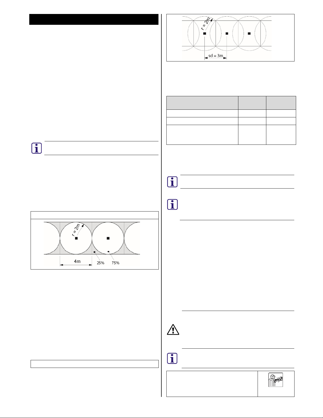
4. Coverage area
The area monitored by the detector is referred to as the
coverage area. It covers the area around the detector with an
operating radius (r).
Detector coverage
Joints in the construction of the vault may impair the
transmission of the signal. Doors must have their own
detector installed to provide the correct coverage.
Tightly sealed corners and edges may reduce the operating
radius (r) by >25%, therefore, corners and edges on steel
vaults must be seamlessly welded. Incorrect positioning can
reduce the coverage area. It is recommended that detectors
are installed on each plane (walls, floor, and ceiling) of the
protected area. Coverage from adjoining planes should not
form part of a comprehensive protection strategy.
4.1. Detector spacing distance
Detectors should be positioned so that they cover the entire
area to be monitored. The distance between detectors is
referred to as the spacing distance (sd).
Detector spacing distance (sd)
To ensure complete coverage of the protected area, the
following formula should be applied to determine the correct
spacing distance between seismic detectors.
Spacing distance (sd) = operating radius(r) x 2 x 0.75
Example:
Material Operating
radius
Spacing
distance
Steel 2m 3m
Concrete 4m 6m
LWS (Systems of armour plating
1.5m 2.25m
with synthetic/composite
materials)
5. Installation
5.1. Direct Installation on steel
The ISP-SM90-120 seismic detector can be installed directly
onto a flat, even metal surface.
Take note of the orientation of the ISP-SM90-120
seismic detector and the required drill pattern.
There must be a direct connection between the
detector and the mounting surface. Paint, varnish,
dirt, silicone or similar materials will impede the
acoustics. Remove these materials from the
mounting location before installation.
Use the ISP-SM90-120 drilling template (provided) to
determine the location of the required holes.
1. Drill 3 x 3.2mm holes, 6mm deep. 2 holes for the
detector and 1 hole for the ISN-GMX-S1 internal test
transmitter (Fig. 1, item H).
2. Remove the drilling template.
3. Thread all holes to M4.
4. Secure the detector and the test transmitter to the
mounting surface.
5.2. Installation on steel using the ISN-GMX-P0 mounting
plate
Use the weld symbol side of the ISN-GMX-P0 mounting plate
(Fig. 2) to install the detector on uneven or reinforced steel
surfaces.
The ISN-GMX-P0 mounting plate can be used for
installing a seismic detector on a steel surface. It is
essential to use the correct side and mounting
methods. The ISN-GMX-P0 displays a detector
symbol to indicate the direction of the cable access
to the detector.
Take note of the orientation of the ISP-SM90-120
seismic detector and the required orientation of
the ISN-GMX-P0 mounting plate.
ISN-GMX-P0 weld symbol
F.01U.331.565-01 3 © 2016 Bosch Security Systems, Inc.
Page 4
Detector symbol showing cable access at
top
1. With the weld symbol visible, attach the ISN-GMX-P0 to
the mounting surface using two fillet welds as shown
(Fig. 3, item B).
If welding is not possible, use the ISN-GMX-P0 as a drill
template.
• Mark the 3 centrally located countersunk holes (Fig.
3, item A).
• Drill 3 x 3.2mm Ø holes (depth to be determined by
the thickness of the mounting surface).
• Thread to M4.
• Secure the ISN-GMX-P0 using 3 x M4 countersunk
screws (provided with ISN-GMX-P0).
2. Mount the detector on to the ISN-GMX-P0.
3. Mount the ISN-GMX-S1 internal test transmitter on the
designated location on the ISN-GMX-P0 (Fig. 3, item C)
and connect to the detector (Fig. 1, item E).
5.3. Installation on concrete using the ISN-GMX-P0
mounting plate
Use the drill symbol side of the ISN-GMX-P0 mounting plate
(Fig. 4) to install the detector on concrete surfaces.
The ISN-GMX-P0 mounting plate can be used for
installing a seismic detector on a concrete surface.
It is essential to use the correct side and mounting
methods. The ISN-GMX-P0 displays a detector
symbol to indicate the direction of the cable access
to the detector.
Take note of the orientation of the ISP-SM90-120
seismic detector and the required orientation of
the ISN-GMX-P0 mounting plate.
ISN-GMX-P0 drill symbol
Detector symbol showing cable access at
top
1. Use the ISP-SM90-120 drilling template (provided) to
determine the location of the required holes.
2. Drill a 10mm Ø x 60mm hole and insert the steel
expansion plug.
3. Drill a 5mm Ø x >22mm hole and insert the ISN-GMX-S1
brass expansion plug.
When installing on concrete, the ISN-GMX-S1 must
not have any contact with the ISN-GMX-P0
mounting plate. The ISN-GMX-S1 must be attached
to the concrete using the M4 x 21mm screw and the
associated brass expansion plug.
4. Secure the ISN-GMX-P0 to the steel expansion plug with
the M6 x 47mm screw.
5. Secure the ISN-GMX-S1 to the brass expansion plug with
the M4 x 21mm screw.
6. Mount the detector on to the ISN-GMX-P0.
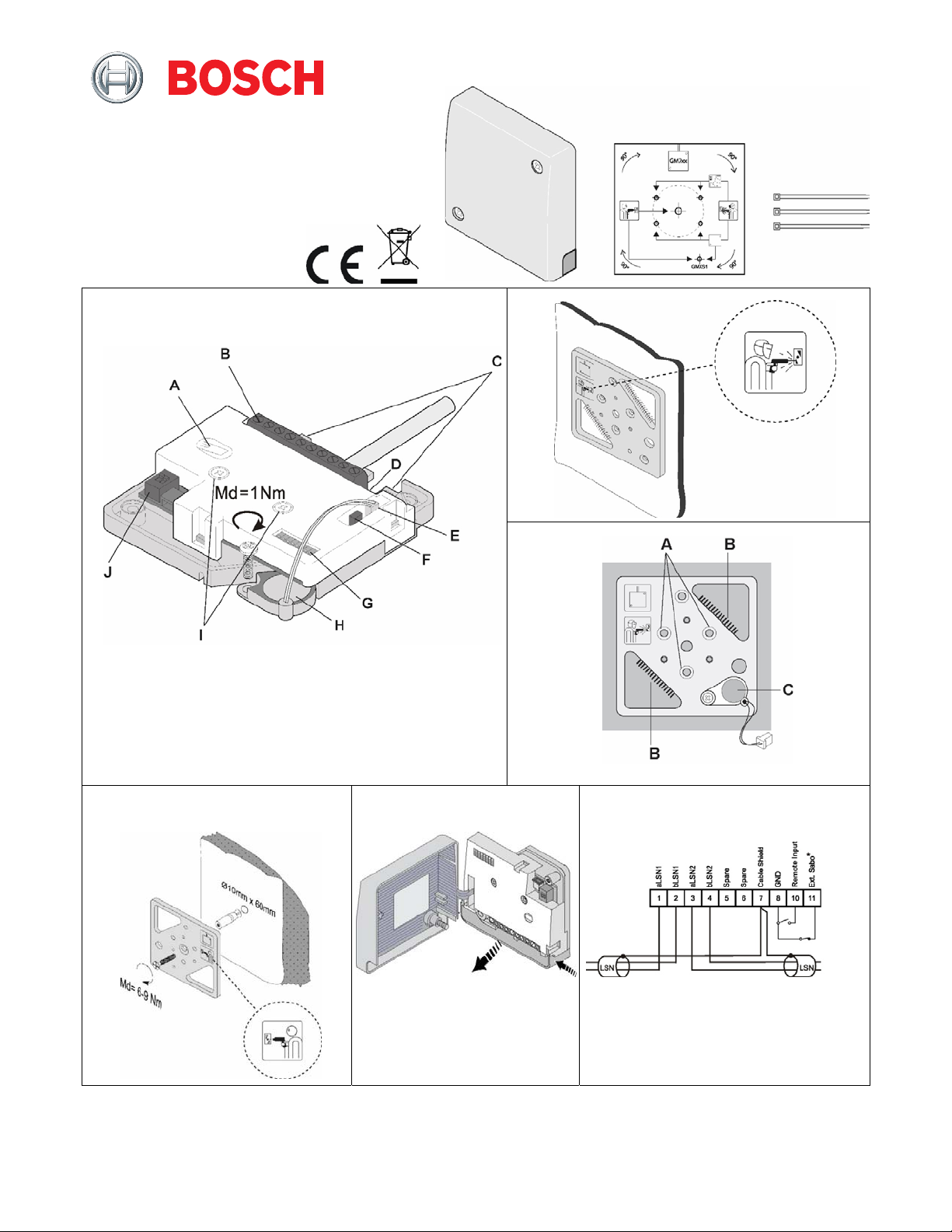
6. Mounting the detector
1. Remove the cover from the detector.
2. Attach the detector to the prepared mounting base using
the two mounting screws (Fig. 1, items I).
3. Remove the cable access skirt (Fig. 5).
4. Wire the connection cables to the terminal (Fig. 1, item
B) as shown in diagram (Fig. 6).
5. Secure the cable to a cable anchor (Fig. 1, items C) with
a cable tie (provided).
6. Connect the accessories and program the detector.
7. Remove the pre-formed cable access points as required
to enable cable access through the skirt (Fig. 5).
8. Replace the cable access skirt.
The cables connected to terminals 8, 10 and 11
must not exceed 3m in length.
The polarity of the LSN Bus must be maintained.
The screen from the LSN cables must be connected
into terminal 7.
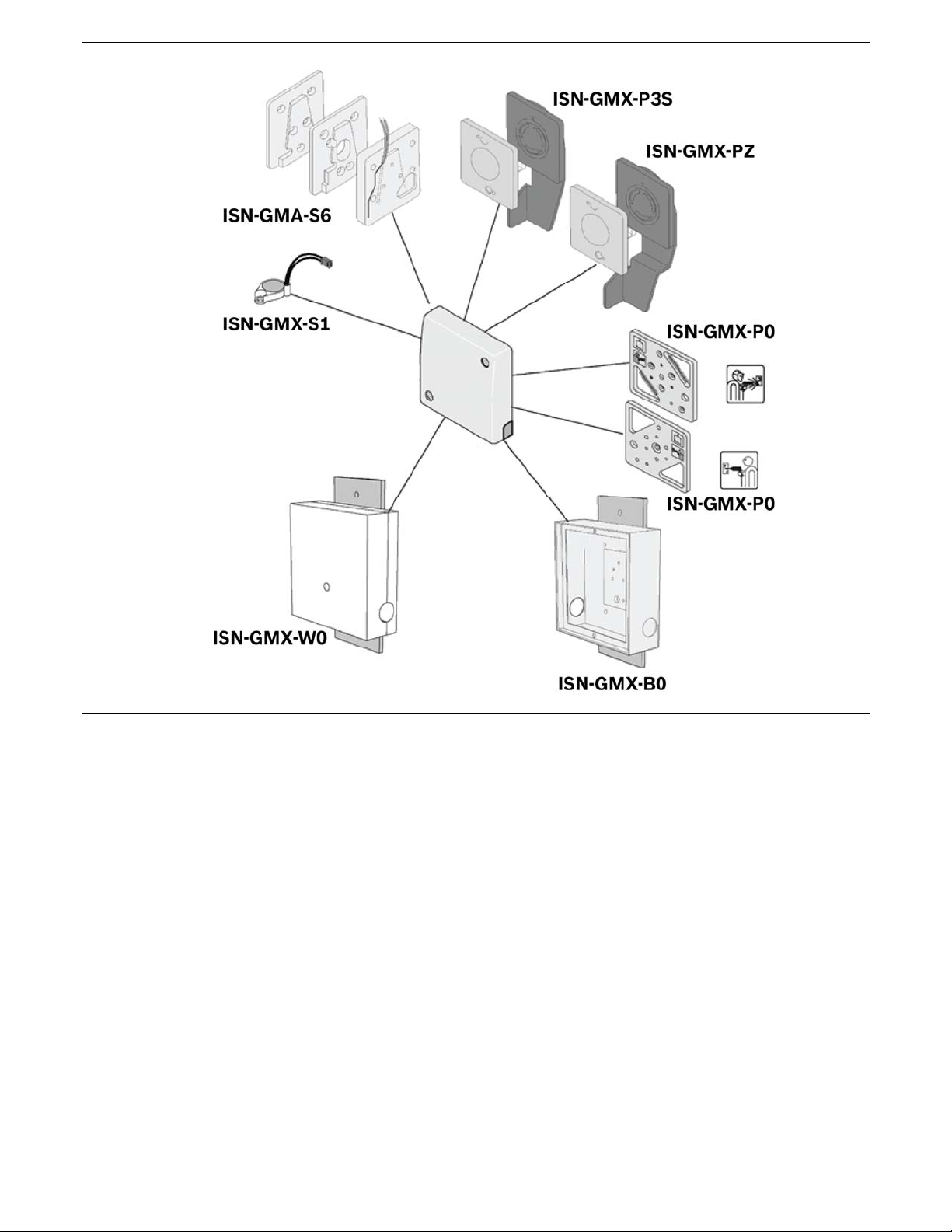
7. Accessories
All of the accessories (Fig. 7) have their own installation
instructions, which are supplied with each accessory. These
installation instructions should be followed for the correct
installation and optimum performance from this seismic
detector. For ordering information, see section 16.
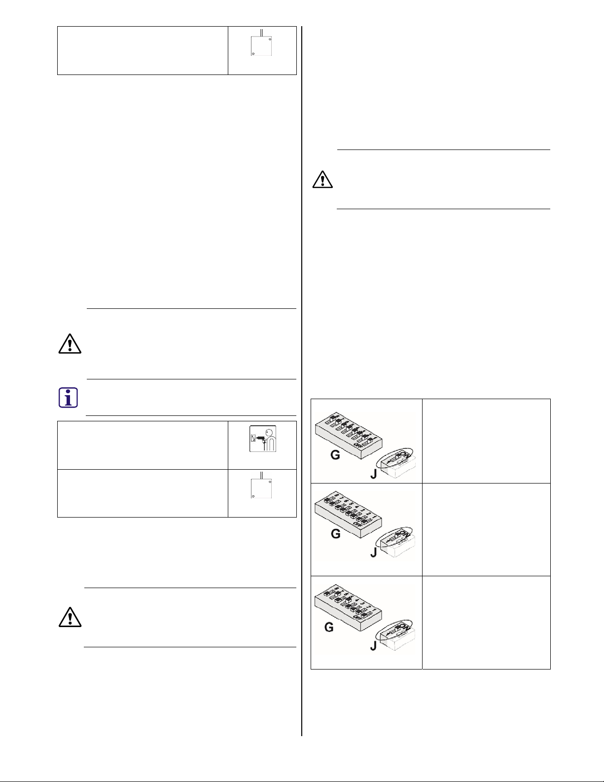
8. Configuration (addressing LSNi/LSN)
ISP-SM90-120 supports LSNi (LSN improved) and LSN (LSN
classic). The detector must be configured using the two DIP
switches (Fig. 1, items G and J) before the power supply is
connected via the LSNi/LSN bus. The DIP switches are used
for configuration and addressing as follows:
• Fig. 1, item G – Addressing
• Fig. 1, item J – Material and coverage application
The following configurations are possible:
LSN application
Fig. 1, item G all in ON
position
Fig. 1, item J in ON position
(default setting)
LSNi application with
automatic addressing
Fig. 1, item G all in OFF
position
Fig. 1, item J in ON position
LSNi application with
manual addressing
Fig. 1, item G set to the
corresponding address (see
the table in the Appendix at
the end of this document).
Fig. 1, item J ON position
F.01U.331.565-01 4 © 2016 Bosch Security Systems, Inc.
Page 5

LSN application in GM570LSN
compatibility mode
This mode enables compatible
use of ISP-SM90-120 in
existing installations to replace
a GM570LSN detector.
The detection characteristics
are identical in all
8.1. External tamper contact
The detector provides the option of connecting an
additional, external tamper contact (for example, the ISNGMA-S6 or the ISN-GMX-P3S). Connect the external tamper
contact to terminal 11 Ext. Sabo and terminal 8 GND (Fig.
6).
The external tamper contact is enabled via the DIP switch
(Fig. 1, item J) with switch 2 in the ON position as follows:
ON
OFF
8.2. Remote sensitivity input (Fig. 6, terminal 10)
When this input is active, the sensitivity of the
detector is reduced. The sensitivity input should
only be applied under special circumstances, and
only for short periods of time. Any reduction in
sensitivity must comply with applicable regulations
such as VdS in Germany. Remote sensitivity is
activated by linking terminal 8 to terminal 10.
Sensitivity is reduced to 12.5% of the original setting for the
duration of the remote sensitivity input. A potential
application is the prevention of alarm triggering where loud
functional noises prevail
configurations.
Fig. 1, item G any position
Fig. 1, item J in OFF position
Switch 2 ON = Internal tamper
contacts only
Switch 2 OFF = Internal and
external tamper contacts
Link terminal 8 to terminal
11 to prevent a tamper
signal (Fig. 6)
9. Programming via LSNi/LSN control panel
The detector is programmed using the configuration
software of the corresponding control panel.
10. Effective operating radius
The specified operating radius applies to an attack with an
oxygen lance. If attacked with a mechanical tool (e.g. a drill)
the value may be as much as three times higher. The
specified operating radius is a guideline which is heavily
influenced by the characteristics of the material and the type
of construction.
11. Shock sensitivity
Shock sensitivity defines how the detector responds to
individual strikes to the substructure of the detector. It is
only possible to set the shock sensitivity for the mode and
effective radius independently in USER MODE with the
LSNi/LSN control panel.
Mode Effective
radius
Concrete 5m* High Vault
Shock
sensitivity*
Example of use
Mode Effective
radius
Concrete 4m. High Vault, modular vault
Concrete 2.5m. High Vault, modular vault
Steel 2m. Medium
Steel 1.5m. Medium
Steel 1m* Low ATM, safe, vault door
LWS 2m. High
LWS 1.5m. High
*Modes not available in GM570LSN compatibility mode
*Availability of these options depends on the ability of the
control panel to identify the detector as a ISP-SM90-120.
Some control panels may identify the ISP-SM90-120 as a
GM570LSN.
11.1. Function test
The LSNi/LSN control panel can trigger a function test in
conjunction with an installed ISN-GMX-S1 internal test
transmitter. The ISN-GMX-S1 is activated through the control
panel using a seismic test function. An alarm is activated if
the detector is working correctly (activation time <3s).
11.2. Automatic self-test
The LSNi/LSN control panel can set the time interval
(hour/day/week) for automatic self-test. The control panel
identifies any unsuccessful self-test.
The detector must be fitted with a ISN-GMX-S1 internal test
transmitter.
Shock
sensitivity*
Example of use
Armor-plated safe,
vault door
Armor-plated safe,
vault door, ATM
Systems of armour
plating with
synthetic /
composite materials
Systems of armour
plating with
synthetic /
composite materials
12. Commissioning
1. Initialize the LSNi/LSN bus
2. Wait 60 seconds.
The detector is now operational.
3. Verify the correct radius and material type have been
selected by the control panel.
Using a multimeter (Ri ≥ 20 kΩ) at terminal 1 (0 V) and TP
(Fig. 1, item D) to monitor for the analogue integration
signal:
Quiescent level 0 V
Integration start 1 V
Alarm threshold (w/o load) 3 V
12.1. Functional checks
Functional checks can be performed as follows:
• With the cover removed, scratch the metal case of the
detector with a screw driver.
• Activate the ISN-GMX-S1 internal test transmitter
through the control panel using a seismic test function.
• Apply the required input to activate the GMXS5 external
test transmitter, if provided.
• Simulate an attack on the protected space.
• Carefully replace the cover and secure it in place.
F.01U.331.565-01 5 © 2016 Bosch Security Systems, Inc.
Page 6

13. Service
The function of the detector and its mounting should be
checked at least once a year as follows:
• Functionally test the detector as detailed in section 12.1.
• Verify the settings of the detector by the control panel
menu options.
• Check the mounting of the detector to ensure that the
detector is securely attached.
• Check that there is a direct connection between the
detector and the mounting surface. Paint, varnish, dirt,
silicone or similar materials will impede the acoustics.
Refer to local approvals for guidance on this matter.
14. Modular vaults
The following principles must be strictly observed when
using seismic detectors on modular vaults made from steel
or concrete:
• Thickness from 100 to 400mm
• Width up to 1000mm
• Length up to 6500mm
Modules with detector
arrangement
1 2 3 4 5 1 2 3 4 5 . . . .
Recommended setting
On maximum 5 modules at a
maximum height of 6.5m
On maximum 3 modules at a
maximum height of 4m
On doors Steel 2m
Concrete 4m
Concrete 2.5m
15. Technical data
Dimensions 89mm x 89mm x 23mm
Supply voltage (LSNi/LSN) Vmax. = 33 V DC
Current consumption
(LSNi/LSN)
Tamper monitoring:
• Microswitch, cover +
removal
• External tamper contact
(Fig.6, terminal 11)
o Closed resistor < 20 kΩ
o Open resistor > 650 kΩ
• Anti-drilling foil in cover
(optional)
Ityp. = 1.2 mA
Imax. = 1.625 mA
Opens on sabotage
Damage = sabotage
• For sensitivity reduction LOW < 1.5 V DC
Operating temperature -25 ºC to +70 ºC
Storage temperature -50 ºC to +70 ºC
Air humidity (EN 60721),
non-condensing
Approvals See the type plate inside the
< 95%
detector cover (Fig. 5).
Corner joints between walls
seamlessly welded
Always 1 detector on
doors
16. Ordering information
1. One detector for a maximum of 5 wall modules. The
detector must be mounted on the middle module.
2. In addition to being bolted together, all of the joints
between the modules must be welded every 400 −
500mm with a 30 − 40mm seam.
3. Corner joints between wall modules must be seamlessly
welded if the coverage area is to extend beyond the
corners.
4. In the case of wall modules equipped with detectors, the
immediately adjoining floor and/or ceiling modules can
be included in the coverage area if the corresponding
butt joints are seamlessly welded.
5. Where building vaults use modules of varying thickness,
the butt joints must be seamlessly welded.
6. Avoid mounting detectors on modules to which guide
rails for cassette transport lifts, ventilators or other
mechanical equipment are attached.
7. Always equip modules which have a pay-in/withdrawal
slot with a detector. This will also be able to monitor the
adjacent modules.
8. All doors must always be equipped with a detector.
9. Programming:
F.01U.331.565-01 6 © 2016 Bosch Security Systems, Inc.
ISP-SM90-120
Seismic detector
ISN-GMX-P0
Mounting
ISN-GMX-S1
Internal test transmitter
ISN-GMX-W0
Wall/Ceiling recess box
ISN-GMX-B0
Floor recess box
ISN-GMX-P3S
Swivel plate
ISN-GMX-P3SZ
Swivel plate
ISN-GMA-S6
Movable mounting kit
ISN-GMX-D7
Anti-drill foil (10x)
F.01U.173.560
F.01U.003.366
F.01U.003.371
F.01U.003.372
F.01U.003.365
F.01U.003.368
F.01U.003.370
F.01U.003.363
F.01U.004.305
de
1. EG-Konformitätserklärung
Hiermit erklärt Bosch Security Systems, Inc. dass dieser
Gerätetyp den Anforderungen aller relevanten EU-Richtlinien
für die CE-Kennzeichnung entspricht. Ab dem 20.04.2016
Page 7

entspricht er der Richtlinie 2014/30/EU (Richtlinie über
elektromagnetische Verträglichkeit).
2. Anwendung
Der Körperschallmelder ISP-SM90-120 ist geeignet für den
Einsatz im lokalen Sicherheitsnetzwerk LSNi (oder LSN) und
hat eine Schleifenverbindung zur Zentrale. Der Melder
erkennt zuverlässig Aufbruchversuche bei Safes,
Geldautomaten, Nachttresoren, Leichtbausafes,
Stahlkammern und modularen Tresor-räumen aus Stahl oder
Beton. Die intelligente Signalverarbeitung erlaubt eine
individuelle Einstellung der Detektionsempfindlichkeit und
somit eine hohe Sicherheit gegen Falschalarm. Der
Sabotageschutz in der Melderabdeckung (Abb. 1, Element A)
und auf der Rückseite des ISP-SM90-120 erkennt ein Öffnen
und ein gewaltsames Entfernen des Melders.
Die Montage, Programmierung und Inbetriebnahme
müssen durch Fachpersonen erfolgen.
3. Inhalt
• 1 Körperschallmelder ISP-SM90-120
• 1 Bohrschablone ISP-SM90-120
• 3 Kabelbinder
4. Wirkbereich
Die vom Melder überwachte Fläche wird als Wirkbereich
bezeichnet. Dieser breitet sich kreisförmig vom Melder mit
einem Wirkradius (r) aus.
Melderwirkung
Verbindungsstellen in der Tresorkonstruktion können die
Signalübertragung beeinträchtigen. Türen müssen über einen
eigenen Melder verfügen, um eine ordnungsgemäße
Melderwirkung zu erzielen.
Gut abgedichtete Ecken und Kanten könnten den Wirkradius
(r) um > 25 % verringern, weshalb Ecken und Kanten bei
Stahltresoren durchgehend verschweißt sein müssen. Eine
falsche Positionierung kann den Wirkbereich reduzieren. Es
wird empfohlen, auf jeder Fläche (Wände, Boden und Decke)
des zu schützenden Bereichs Melder zu montieren. Eine
Erfassung von angrenzenden Flächen aus sollte nicht
Bestandtteil einer umfassenden Schutzstrategie sein.
4.1. Melderabstand
Melder müssen so positioniert werden, dass sie den
gesamten zu überwachenden Bereich abdecken. Der Abstand
zwischen den Meldern wird als Melderabstand bezeichnet
(sd – engl. spacing distance).
Melderabstand (sd)
Für eine vollständige Abdeckung des zu schützenden
Bereichs sollte die folgende Formel angewendet werden, um
den korrekten Abstand zwischen den Körperschallmeldern zu
bestimmen.
Melderabstand (sd) = Wirkradius (r) × 2 × 0,75
Beispiel:
Material Wirkradius Melderabstand
Stahl 2m 3m
Beton 4m 6m
LWS (Panzerungssysteme mit
1,5m 2,25m
Kunststoffen/Verbundwerkstoffen)
5. Montage
5.1. Direkte Montage auf Stahl
Der Körperschallmelder ISP-SM90-120 kann direkt auf einer
flachen, ebenen Metallfläche montiert werden.
Achten Sie darauf, dass der Körperschallmelder ISPSM90-120 und das passende Bohrmuster
aufeinander ausgerichtet sind.
Zwischen Melder und Montagefläche muss eine
direkte Verbindung bestehen. Farben, Lacke,
Schmutz, Silikon o. Ä. behindern die
Schallübertragung. Entfernen Sie diese Materialien
von der Montagefläche, bevor Sie mit der Montage
beginnen.
Verwenden Sie die beiliegende Bohrschablone ISP-SM90120, um die Position der erforderlichen Bohrungen zu
bestimmen.
1. Bohren Sie drei Löcher mit einem Durchmesser von
3,2 mm und einer Tiefe von 6 mm. Zwei Löcher für den
Melder und ein Loch für den internen Prüfsender ISNGMX-S1 (Abb. 1, Element H).
2. Entfernen Sie die Bohrschablone.
3. Schneiden Sie in alle Bohrungen ein M4-Gewinde.
4. Befestigen Sie den Melder und den Prüfsender auf der
Montagefläche.
5.2. Montage auf Stahl mithilfe der Montageplatte ISN-
GMX-P0
Verwenden Sie die Seite der Montageplatte ISN-GMX-P0 mit
dem Schweißsymbol (Abb. 2), um den Melder auf unebenen
oder verstärkten Stahlflächen zu montieren.
Die Montageplatte ISN-GMX-P0 kann für die
Montage eines Körperschallmelders auf einer
Stahlfläche verwendet werden. Es ist
ausschlaggebend, dass die richtige Seite und die
korrekten Montagemethoden verwendet werden.
Die ISN-GMX-P0 trägt ein Meldersymbol, das die
Ausrichtung der Kabelzuführung zum Melder
anzeigt.
Achten Sie darauf, dass der
Körperschallmelder ISP-SM90-120 und die
Montageplatte ISN-GMX-P0 zueinander
ausgerichtet sind.
ISN-GMX-P0-Schweißsymbol
F.01U.331.565-01 7 © 2016 Bosch Security Systems, Inc.
Page 8

Meldersymbol mit Kabelzuführung auf
Oberseite
1. Befestigen Sie die Montageplatte ISN-GMX-P0 mit zwei
Kehlnähten auf der Montagefläche. Das Schweißsymbol
muss sichtbar sein (siehe Abb. 3, Element B).
Wenn kein Schweißen möglich ist, verwenden Sie die
ISN-GMX-P0 als Bohrschablone.
• Markieren Sie die drei mittig liegenden
Senkbohrungen (Abb. 3, Element A).
• Bohren Sie drei Löcher mit einem Durchmesser von
3,2 mm (die Tiefe der Bohrung muss abhängig von
der Stärke der Montagefläche bestimmt werden).
• Schneiden Sie anschließend M4-Gewinde in alle
Bohrungen.
• Befestigen Sie die ISN-GMX-P0 mithilfe von
Senkkopfschrauben (3 × M4, im Lieferumfang der
ISN-GMX-P0 enthalten).
2. Montieren Sie den Melder auf der ISN-GMX-P0.
3. Montieren Sie den internen Prüfsender ISN-GMX-S1 an
der angegebenen Position auf der ISN-GMX-P0 (Abb. 3,
Element C), und schließen Sie ihn an den Melder an
(Abb. 1, Element E).
5.3. Montage auf Beton mithilfe der Montageplatte ISN-
GMX-P0
Verwenden Sie die Seite der Montageplatte ISN-GMX-P0 mit
dem Bohrsymbol (Abb. 4), um den Melder auf Betonflächen
zu montieren.
Die Montageplatte ISN-GMX-P0 kann für die
Montage eines Körperschallmelders auf einer
Betonfläche verwendet werden. Es ist
ausschlaggebend, dass die richtige Seite und die
korrekten Montagemethoden verwendet werden.
Die ISN-GMX-P0 trägt ein Meldersymbol, das die
Ausrichtung der Kabelzuführung zum Melder
anzeigt.
Achten Sie darauf, dass der
Körperschallmelder ISP-SM90-120 und die
Montageplatte ISN-GMX-P0 zueinander
ausgerichtet sind.
ISN-GMX-P0-Bohrsymbol
Meldersymbol mit Kabelzuführung auf
Oberseite
1. Verwenden Sie die beiliegende Bohrschablone ISP-
SM90-120, um die Position der erforderlichen
Bohrungen zu bestimmen.
2. Bohren Sie ein Loch mit einem Durchmesser von 10 mm
und einer Tiefe von 60 mm, und setzen Sie den
Stahlspreizdübel ein.
3. Bohren Sie ein Loch mit einem Durchmesser von 5 mm
und einer Tiefe von > 22 mm, und setzen Sie den ISNGMX-S1-Messingspreizdübel ein.
Bei der Montage auf Beton darf der ISN-GMX-S1
keinen Kontakt mit der Montageplatte ISN-GMX-P0
haben. Der ISN-GMX-S1 muss mithilfe der Schraube
(M4 × 21 mm) und dem dazugehörigen
Messingspreizdübel am Beton befestigt werden.
4. Befestigen Sie die ISN-GMX-P0 mithilfe der Schraube
(M6 × 47 mm) am Stahlspreizdübel.
5. Befestigen Sie den ISN-GMX-S1 mit der Schraube
(M4 × 21 mm) am Messingspreizdübel.
6. Montieren Sie den Melder auf der ISN-GMX-P0.
6. Montage des Melders
1. Entfernen Sie die Abdeckung vom Melder.
2. Befestigen Sie den Melder mithilfe der zwei
Befestigungsschrauben auf der vorbereiteten
Montageplatte (Abb. 1, Element I).
3. Entfernen Sie die Verkleidung der Kabelzuführung
(Abb. 5).
4. Führen Sie die Verbindungskabel zur Zentrale (Abb. 1,
Element B) wie in der Abbildung dargestellt (Abb. 6).
5. Befestigen Sie das Kabel mit einem (beiliegenden)
Kabelbinder an einer Kabelklemme (Abb. 1, Element C).
6. Schließen Sie das Zubehör an und programmieren Sie
den Melder.
7. Entfernen Sie die vorgestanzten Abdeckungen an den
Kabelzuführungsaussparungen wie erforderlich, um die
Kabelzuführung durch die Verkleidung zu ermöglichen
(Abb. 5).
8. Bringen Sie die Verkleidung der Kabelzuführung wieder
an.
Die mit den Klemmen 8, 10 und 11 verbundenen
Kabel dürfen nicht länger als 3 m sein.
Die Polarität des LSN-Busses muss erhalten bleiben.
Die Abschirmung der LSN-Kabel muss mit Klemme 7
verbunden werden.
7. Zubehör
Für alle Zubehörteile (Abb. 7) gelten eigene
Montageanweisungen, die jedem Zubehörteil beiliegen.
Diese Montageanweisungen müssen für die korrekte
Montage und eine optimale Leistung dieses
Körperschallmelders befolgt werden. Bestellangaben siehe
Abschnitt 16.
8. Konfiguration (LSNi/LSN-Adressierung)
Der ISP-SM90-120 unterstützt LSNi (LSN improved) und LSN
(LSN classic). Der Melder muss mithilfe der zwei DIPSchalter konfiguriert werden (Abb. 1, Elemente G und J),
bevor die Stromversorgung über den LSNi/LSN-Bus
angeschlossen wird. Die DIP-Schalter werden wie folgt für
die Konfiguration und Adressierung verwendet:
• Abb. 1, Element G – Adressierung
• Abb. 1, Element J – Material- und
Abdeckungsanwendung
Folgende Konfigurationen sind möglich:
LSN-Anwendung
Abb. 1, Element G alle in EINPosition
Abb. 1, Element J in EINPosition
(Werkseinstellung)
F.01U.331.565-01 8 © 2016 Bosch Security Systems, Inc.
Page 9

LSNi-Anwendung mit
automatischer Adressierung
Abb. 1, Element G alle in AUSPosition
Abb. 1, Element J in EINPosition
8.1. Externer Sabotagekontakt
Der Melder bietet die Möglichkeit, einen zusätzlichen,
externen Sabotagekontakt (z. B. ISN-GMA-S6 oder ISN-GMX-
P3S) anzuschließen. Schließen Sie den externen
Sabotagekontakt an Klemme 11 Ext. Sabo und Klemme 8
GND (Abb. 6) an.
Der externe Sabotagekontakt wird über den DIP-Schalter
(Abb. 1, Element J) mit Schalter 2 in der EIN-Position wie
folgt aktiviert:
EIN
AUS
8.2. Fernempfindlichkeitseingang (Abb. 6, Klemme 10)
Wenn dieser Eingang aktiv ist, wird die
Melderempfindlichkeit verringert. Der
Empfindlichkeitseingang darf nur unter bestimmtem
Umständen angewendet werden, und das nur für
kurze Zeiträume. Die Reduzierung der
Empfindlichkeit muss in Übereinstimmung mit den
geltenden Vorschriften (z. B. gemäß VdS) erfolgen.
Die Fernempfindlichkeit wird durch Verbindung der
Klemme 8 mit Klemme 10 aktiviert.
LSNi-Anwendung mit
manueller Adressierung
Einstellung von Element G in
Abb. 1 auf die entsprechende
Adresse (siehe Tabelle im
Anhang am Ende des
Dokuments).
Abb. 1, Element J EIN-Position
LSN-Anwendung im
GM570LSNKompatibilitätsmodus
Dieser Modus ermöglicht den
kompatiblen Einsatz des ISPSM90-120 in bestehenden
Installationen als Ersatz eines
GM570LSN-Melders.
Die Detektionseigenschaften
sind in allen Konfigurationen
identisch.
Abb. 1, Element G beliebige
Position
Abb. 1, Element J in AUSPosition
Schalter 2 EIN = Nur interne
Sabotagekontakte
Schalter 2 AUS = Interne und
externe Sabotagekontakte
Verbinden Sie Klemme 8
mit Klemme 11, um ein
Sabotagesignal zu
verhindern (Abb. 6).
Die Empfindlichkeit wird für die Dauer des Signals am
Fernempfindlichkeitseingang auf 12,5 % der
Originaleinstellung reduziert. Eine potentielle Anwendung ist
die Verhinderung der Alarmauslösung bei starken
funktionsbedingten Geräuschen.
9. Programmierung über LSNi/LSN-Zentrale
Die Programmierung des Melders erfolgt über die
Konfigurationssoftware der entsprechenden Zentrale.
10. Wirkradius
Der angegebene Wirkradius gilt für einen Angriff mit
Sauerstofflanze. Bei einem Angriff mit mechanischem
Werkzeug (z. B. Bohrer) kann sich der Wert bis auf das
Dreifache erhöhen. Der angegebene Wirkradius ist ein
Richtwert, der stark von der Beschaffenheit des Untergrunds
beeinflusst wird.
11. Schlagempfindlichkeit
Die Schlagempfindlichkeit definiert, wie der Melder auf
einzelne Schläge auf den Untergrund des Melders reagiert.
Die unabhängige Einstellung der Schlagempfindlichkeit von
Modus und Wirkradius ist nur im USER MODE über die
LSNi/LSN-Zentrale möglich.
Modus Wirkradius
Beton 5m* Hoch Tresorraum
Beton 4m Hoch
Beton 2,5m Hoch
Stahl 2m Mittel
Stahl 1,5m Mittel
Stahl 1m* Niedrig
LWS 2m Hoch
LWS 1,5m Hoch
*Modi nicht im GM570LSN-Kompatibilitätsmodus verfügbar
*Ob diese Optionen verfügbar sind, hängt davon ab,
inwiefern die Zentrale den Melder als einen ISP-SM90-120
erkennt. Einige Zentralen könnten den ISP-SM90-120 als ein
GM570LSN identifizieren.
11.1. Funktionstest
Die LSNi/LSN-Zentrale kann zusammen mit einem
montierten internen Prüfsender ISN-GMX-S1 einen
Funktionstest auslösen. Der ISN-GMX-S1 wird über die
Zentrale mithilfe einer Schallmeldetestfunktion aktiviert. Bei
korrekt funktionierendem Melder löst dieser Alarm aus
(Auslösezeit < 3 s).
11.2. Automatischer Selbsttest
Mit der LSNi/LSN-Zentrale kann das Zeitintervall
(Stunde/Tag/Woche) für den automatischen Selbsttest
Schlag-
empfindlichkeit*
Anwendungsbeispiel
Tresorraum,
Elementtresor
Tresorraum,
Elementtresor
Panzer-Geldschrank,
Tresorraumtür
Panzer-Geldschrank,
Tresorraumtür,
Geldautomat
Geldautomat, Safe,
Tresortür
Panzerungssysteme
mit
Kunststoffen/Verbun
dwerkstoffen
Panzerungssysteme
mit
Kunststoffen/Verbun
dwerkstoffen
F.01U.331.565-01 9 © 2016 Bosch Security Systems, Inc.
Page 10

festgelegt werden. Die Zentrale erkennt jeden
fehlgeschlagenen Selbsttest.
Der Melder muss mit einem internen Prüfsender ISN-GMX-S1
ausgestattet sein.
12. Inbetriebnahme
1. Initialisieren Sie den LSNi/LSN-Bus.
2. Warten Sie 60 Sekunden.
Der Melder ist nun betriebsbereit.
3. Überprüfen Sie, ob der korrekte Radius und Materialtyp
mithilfe der Zentrale gewählt wurden.
Überprüfen Sie mithilfe eines Multimeters (Ri ≥ 20 kΩ) an
Klemme 1 (0 V) und Testpunkt (Abb. 1, Element D) das
analoge Integrationssignal:
Ruhepegel 0 V
Integrationsstart 1 V
Alarmschwelle (unbelastet) 3 V
12.1. Funktionsprüfungen
Funktionsprüfungen können wie folgt ausgeführt werden:
• Nehmen Sie die Abdeckung ab und kratzen Sie das
Metallgehäuse des Melders mit einem Schraubendreher
an.
• Aktivieren Sie den internen Prüfsender ISN-GMX-S1 über
die Zentrale mithilfe einer Schallmeldetestfunktion.
• Legen Sie das erforderliche Eingangssignal an, um den
externen Prüfsender GMXS5 (falls vorhanden) zu
aktivieren.
• Simulieren Sie einen Angriff auf den zu schützenden
Bereich.
• Setzen Sie die Abdeckung wieder auf und sichern Sie
sie.
13. Service
Die Funktion des Melders und dessen Montage müssen
mindestens einmal jährlich wie folgt geprüft werden:
• Testen Sie den Melder auf eine ordnungsgemäße
Funktion entsprechend Abschnitt 12.1.
• Überprüfen Sie die Einstellungen des Melders mithilfe
der Menüoptionen der Zentrale.
• Überprüfen Sie die Montage des Melders, um
sicherzustellen, dass er sicher befestigt ist.
• Überprüfen Sie, ob ein direkter Kontakt zwischen dem
Melder und der Montagefläche besteht. Farben, Lacke,
Schmutz, Silikon o. Ä. behindern die Schallübertragung.
Siehe lokale Zulassungen für weitere Informationen zu
diesem Thema.
14. Elementtresore
Beim Einsatz des Körperschallmelders in und an
Elementtresoren aus Stahl und Betonmaterial sind folgende
Grundsätze unbedingt zu beachten:
• Stärke von 100 bis 400 mm
• Breite bis 1.000 mm
• Länge bis 6.500 mm
Elemente mit Melderanordnung
1 2 3 4 5 1 2 3 4 5 . . . .
Eckverbindung Wand/Wand
durchgehend verschweißt
Immer 1 Melder an
Türen
1. Ein Melder für jeweils maximal 5 Wandelemente. Der
Melder muss auf dem mittleren Element montiert
werden.
2. Alle Fugen zwischen den Elementen müssen zusätzlich
zu einer Verschraubung punktuell alle 400 bis 500 mm
mit einer 30 bis 40 mm langen Schweißnaht verschweißt
sein.
3. Eckverbindungen bei Wandelementen müssen
durchgehend verschweißt werden, wenn der
Wirkbereich sich auch über die Ecken erstrecken soll.
4. Werden Wandelemente mit Meldern bestückt, kann das
direkt angrenzende Boden- und/oder Deckenelement in
den Wirkbereich mit einbezogen werden, wenn die
entsprechende Stoßstelle durchgehend verschweißt
wird.
5. Wenn in Tresoren unterschiedliche Elementdicken
kombiniert werden, müssen die Stoßstellen
durchgehend verschweißt werden.
6. Bringen Sie Melder soweit möglich nicht auf Elementen
an, an denen Führungsschienen von KassettenTransportlifts, Ventilatoren oder andere mechanische
Einrichtungen befestigt sind.
7. Verwenden Sie immer Elemente, die mit einer Ein-
/Ausgabeöffnung mit Melder ausgestattet sind. Dadurch
können auch die angrenzenden Elemente überwacht
werden.
8. Alle Türen müssen mit einem eigenen Melder
ausgestattet sein.
9. Programmierung:
Empfohlene Einstellung
Auf max. 5 Elementen mit
Beton 4m
max. Höhe von 6,5 m
Auf max. 3 Elementen mit
Beton 2,5m
max. Höhe von 4 m
Auf Türen Stahl, 2m
15. Technische Daten
Abmessungen 89mm × 89mm × 23mm
Versorgungsspannung
(LSNi/LSN)
Stromaufnahme (LSNi/LSN) Ityp. = 1,2 mA
Sabotageüberwachung:
• Mikroschalter,
Abdeckung + Entfernung
• Externer
Sabotagekontakt
(Abb. 6, Klemme 11)
Vmax. = 33 V DC
Imax. = 1,625 mA
Öffnet bei Sabotage
F.01U.331.565-01 10 © 2016 Bosch Security Systems, Inc.
Page 11

o Widerstand
geschlossen
o Widerstand
offen
• Bohrschutzfolie auf der
Innenseite der
Abdeckung (optional)
• Für Absenkung der
Empfindlichkeit
Betriebstemperatur –25 °C bis +70 °C
Lagertemperatur –50 °C bis +70 °C
Luftfeuchtigkeit (EN 60721),
nicht kondensierend
Zulassungen Siehe Typenschild auf
< 20 kΩ
> 650 kΩ
Beschädigung = Sabotage
LOW < 1,5 V DC
< 95 %
Innenseite der Abdeckung
(Abb. 5)
16. Bestellangaben
ISP-SM90-120
Körperschallmelder
ISN-GMX-P0
Montageplatte
ISN-GMX-S1
Interner Prüfsender
ISN-GMX-W0
Wand-/Deckeneinbaudose
ISN-GMX-B0
Bodeneinbaudose
ISN-GMX-P3S
Schlossschutz
ISN-GMX-P3SZ
Schlossschutz
GMAS6
Bewegliches Montagekit
ISN-GMX-D7
Bohrschutzfolie (10×)
F.01U.173.560
F.01U.003.366
F.01U.003.371
F.01U.003.372
F.01U.003.365
F.01U.003.368
F.01U.003.370
F.01U.003.363
F.01U.004.305
F.01U.331.565-01 11 © 2016 Bosch Security Systems, Inc.
Page 12

Appendix Anhang
Settings for the LSNi operating mode with manual addressing
Einstellungen für die Betriebsart LSNi mit manueller Adressierung
Switch setting Fig. 1, item G Schalterstellung Fig. 1, item G
O = OFF 1 = ON O = OFF 1 = ON
87654321 A87654321 A87654321
Adresse
LSNi auto
LSN classic
1
2
3
4
5
6
7
8
9
10
11
12
13
14
15
16
17
18
19
20
21
22
23
24
25
26
27
28
29
30
31
32
33
34
35
36
37
38
39
40
41
42
43
44
45
46
47
48
49
50
51
52
53
54
55
56
57
58
59
60
61
62
63
64
65
66
67
68
69
70
71
72
73
74
75
76
77
78
79
80
81
82
83
84
00000000
00000001
00000010
00000011
00000100
00000101
00000110
00000111
00001000
00001001
00001010
00001011
00001100
00001101
00001110
00001111
00010000
00010001
00010010
00010011
00010100
00010101
00010110
00010111
00011000
00011001
00011010
00011011
00011100
00011101
00011110
00011111
00100000
00100001
00100010
00100011
00100100
00100101
00100110
00100111
00101000
00101001
00101010
00101011
00101100
00101101
00101110
00101111
00110000
00110001
00110010
00110011
00110100
00110101
00110110
00110111
00111000
00111001
00111010
00111011
00111100
00111101
00111110
00111111
01000000
01000001
01000010
01000011
01000100
01000101
01000110
01000111
01001000
01001001
01001010
01001011
01001100
01001101
01001110
01001111
01010000
01010001
01010010
01010011
01010100
85
01010101
86
01010110
87
01010111
88
01011000
89
01011001
90
01011010
91
01011011
92
01011100
93
01011101
94
01011110
95
01011111
96
01100000
97
01100001
98
01100010
99
01100011
100
01100100
101
01100101
102
01100110
103
01100111
104
01101000
105
01101001
106
01101010
107
01101011
108
01101100
109
01101101
110
01101110
111
01101111
112
01110000
113
01110001
114
01110010
115
01110011
116
01110100
117
01110101
118
01110110
119
01110111
120
01111 0 00
121
01111 0 01
122
01111 0 10
123
01111 0 11
124
01111100
125
01111101
126
01111110
127
01111111
128
10000000
129
10000001
130
10000010
131
10000011
132
10000100
133
10000101
134
10000110
135
10000111
136
10001000
137
10001001
138
10001010
139
10001011
140
10001100
141
10001101
142
10001110
143
10001111
144
10010000
145
10010001
146
10010010
147
10010011
148
10010100
149
10010101
150
10010110
151
10010111
152
10011000
153
10011001
154
10011010
155
10011011
156
10011100
157
10011101
158
10011110
159
10011111
160
10100000
161
10100001
162
10100010
163
10100011
164
10100100
165
10100101
166
10100110
167
10100111
168
10101000
169
10101001
170
10101010
171
10101011
172
10101100
173
10101101
174
10101110
175
10101111
176
10110000
177
10110001
178
10110010
179
10110011
180
10110100
181
10110101
182
10110110
183
10110111
184
10111000
185
10111001
186
10111010
187
10111011
188
10111100
189
10111101
190
10111110
191
10111111
192
11000000
193
11000001
194
11000010
195
11000011
196
11000100
197
11000101
198
11000110
199
11000111
200
11001000
201
11001001
202
11001010
203
11001011
204
11001100
205
11001101
206
11001110
207
11001111
208
11010000
209
11010001
210
11010010
211
11010011
212
11010100
213
11010101
214
11010110
215
11010111
216
11011000
217
11011001
218
11011010
219
11011011
220
11011100
221
11011101
222
11011110
223
11011111
224
11100000
225
11100001
226
11100010
227
11100011
228
11100100
229
11100101
230
11100110
231
11100111
232
11101000
233
11101001
234
11101010
235
11101011
236
11101100
237
11101101
238
11101110
239
11101111
240
11110000
241
11110001
242
11110010
243
11110011
244
11110100
245
11110101
246
11110110
247
11110111
248
11111000
249
11111001
250
11111010
251
11111011
252
11111100
253
11111101
254
11111110
F.01U.331.565-01 12 © 2016 Bosch Security Systems, Inc.
 Loading...