

Page 1
GWS 21-180/230 (J)HV
GWS 24-180/230 (J)BV
GWS 26-180/230 (J)BV
PROFESSIONAL
Bedienungsanleitung
Operating instructions
Instructions d’emploi
Instrucciones de servicio
Manual de instruções
Istruzioni d’uso
Gebruiksaanwijzing
Betjeningsvejledning
Bruksanvisning
Brukerveiledningen
Käyttöohje
Οδηγία χειρισµού
Kullan∂m k∂lavuzu
* Des idées en action.
Page 2
METAL
1 605 703 099
1 600 210 039
1 603 340 031
1 603 340 040
1 607 950 048
2 602 025 124
1 601 329 013
1 607 000 247
1 605 510 181
1 605 703 099
1 608 600 231
16
1 608 600 232
24
1 608 600 233
36
1 608 600 234
60
1 608 600 239
24
1 608 600 240
36
1 608 600 241
60
1 603 340 040
1 607 950 004
2 • 1 609 929 F55 • 04.01
Ø 180 mm
Ø 230 mm
Ø 180 mm
Ø 230 mm
Ø 180 mm
Ø 230 mm
1 605 510 222
1 605 510 223
2 605 510 173
2 605 510 174
1 600 793 007
1 605 510 179
1 605 510 180
0 601 999 018
0 601 999 019
F
1 605 438 034
Page 3
3 • 1 609 929 F55 • 04.01
Page 4
GWS 24-180 (J)BV
GWS 24-230 (J)BV
GWS 26-180 (J)BV
GWS 26-230 (J)BV
PROFESSIONAL
3
25
26
1
2
7
8
9
10
5
14
15
6
4
16
10
13 12 10
27 28
19 19
20
11
12
13
4+5 • 1 609 929 F55 • 04.01
17
12
18
21
22
23
24
GWS 21-180 (J)HV
GWS 21-230 (J)HV
PROFESSIONAL
Page 5

Gerätekennwerte
Winkelschleifer GWS 21-180 HV
PROFESSIONAL
GWS 21-230 HV
PROFESSIONAL
GWS 24-180 BV
PROFESSIONAL
Bestellnummer 0 601 851 B.. 0 601 852 B.. 0 601 853 B..
Mit Anlaufstrombegrenzung GWS 21-180 JHV
PROFESSIONAL
GWS 21-230 JHV
PROFESSIONAL
GWS 24-180 JBV
PROFESSIONAL
Bestellnummer 0 601 851 G.. 0 601 852 G.. 0 601 853 G..
Nennaufnahmeleistung* [W] 2 100 2 100 2 400
Abgabeleistung [W] 1 350 1 350 1 700
Leerlaufdrehzahl [min
-1
] 8 500 6 500 8 500
Schleifscheiben-Ø, max. [mm] 180 230 180
Schleifspindelgewinde M 14 M 14 M 14
Gewicht ohne Netzkabel, ca. [kg] 4,4 4,4 5,2
Schutzklasse
Winkelschleifer GWS 24-230 BV
/ II / II / II
GWS 26-180 BV
PROFESSIONAL
PROFESSIONAL
GWS 26-230 BV
PROFESSIONAL
Bestellnummer 0 601 854 B.. 0 601 855 B.. 0 601 856 B..
Mit Anlaufstrombegrenzung GWS 24-230 JBV
PROFESSIONAL
GWS 26-180 JBV
PROFESSIONAL
GWS 26-230 JBV
PROFESSIONAL
Bestellnummer 0 601 854 G.. 0 601 855 G.. 0 601 856 G..
Nennaufnahmeleistung* [W] 2 400 2 600 2 600
Abgabeleistung [W] 1 700 1 800 1 800
Leerlaufdrehzahl [min
-1
] 6 500 8 500 6 500
Schleifscheiben-Ø, max. [mm] 230 180 230
Schleifspindelgewinde M 14 M 14 M 14
Gewicht ohne Netzkabel, ca. [kg] 5,2 5,2 5,2
Schutzklasse
Bitte die Bestellnummer Ihrer Maschine beachten. Die Handelsbezeichnungen einzelner Maschinen können variieren.
Einschaltvorgänge erzeugen kurzfristige Spannungsabsenkungen. Bei ungünstigen Netzbedingungen können Beeinträch-
tigungen anderer Geräte auftreten. Bei Netzimpedanzen kleiner als 0,25 Ohm sind keine Störungen zu erwarten.
* Angaben gelten für Nennspannungen [U] 230/240 V. Bei niedrigeren Spannungen und in länderspezifischen
Ausführungen können diese Angaben variieren.
/ II / II / II
Bestimmungsgemäßer Gebrauch
Das Gerät ist bestimmt zum Trennen, Schruppen
und Bürsten von Metall- und Steinwerkstoffen
ohne Verwendung von Wasser. Zum Trennen
von Stein ist ein Führungsschlitten vorgeschrieben.
Hinweise zur Statik
Schlitze in tragenden Wänden unterliegen der
Norm DIN 1053 Teil 1 oder länderspezifischen
Festlegungen.
Diese Vorschriften sind unbedingt einzuhalten.
Vor Arbeitsbeginn den verantwortlichen Statiker,
Architekten oder die zuständige Bauleitung zu
Rate ziehen.
6 • 1 609 929 F55 • TMS • 18.12.03
Deutsch - 1
Geräusch-/Vibrationsinformation
Messwerte ermittelt entsprechend EN 50 144.
Der A-bewertete Geräuschpegel des Gerätes be-
trägt typischerweise: Schalldruckpegel
90 dB (A); Schallleistungspegel 103 dB (A).
Gehörschutz tragen!
Die Hand-Arm-Vibration ist typischerweise niedriger als 2,5 m/s
2
(1,7 m/s
2
).
Page 6
1
2
3
4
5
6
7
8
9
*
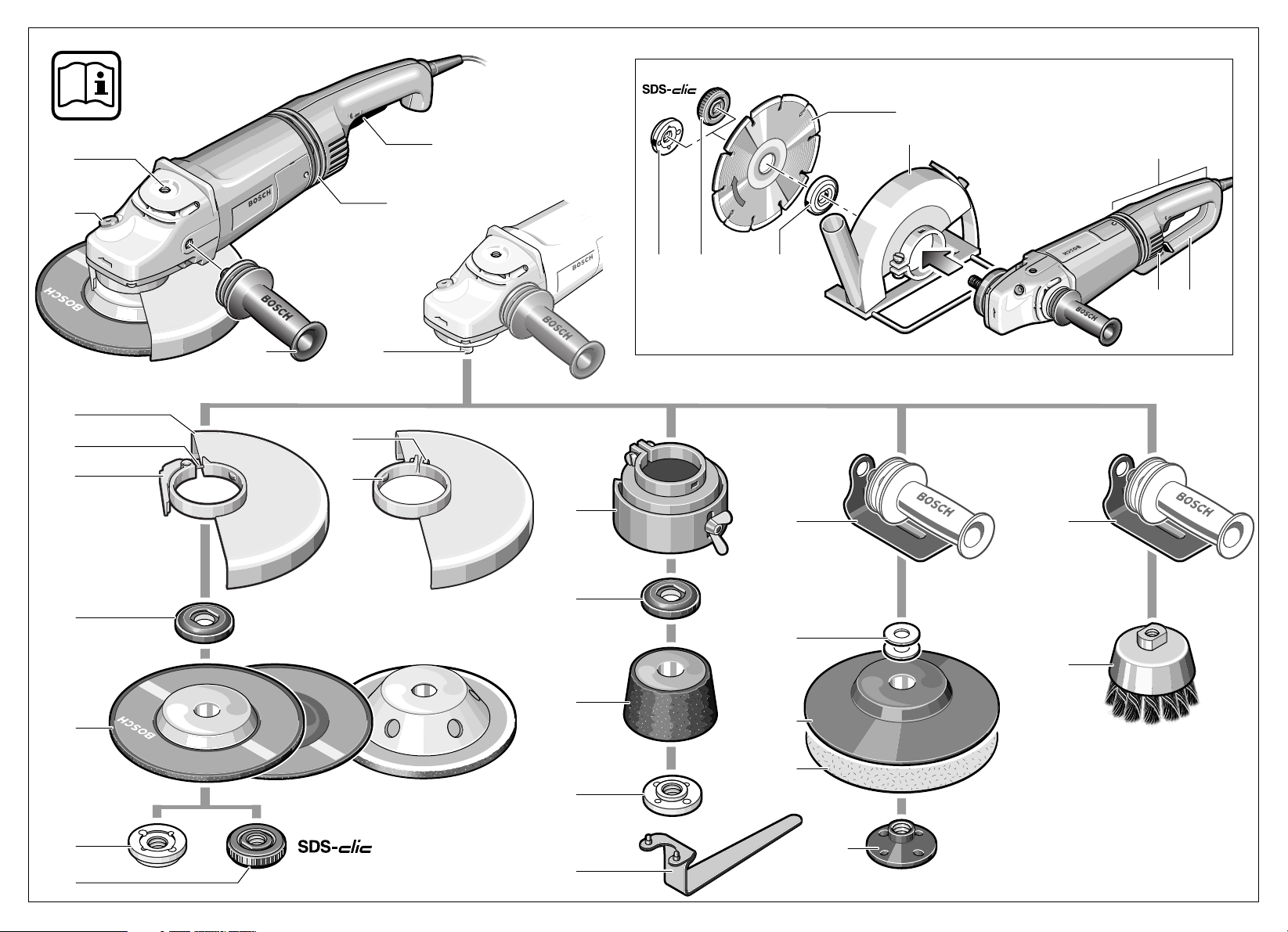
Geräteelemente
Die Nummerierung der Geräteelemente bezieht
sich auf die Darstellung des Gerätes auf der Grafikseite.
Bitte klappen Sie die Aufklappseite mit der Darstellung des Gerätes auf, und lassen Sie diese
Seite aufgeklappt, während Sie die Bedienungsanleitung lesen.
Gewinde Zusatzgriff (3x)
Spindel-Arretiertaste
Ein-/Ausschalter
Vibrationsdämpfung
Zusatzgriff
Schleifspindel
Schutzhaube
Justierschraube
Spannhebel
10 Aufnahmeflansch mit O-Ring
11 Schrupp-/Trennscheibe*
12 Spannmutter
■
■
■
■
■
■
■
■
■
■
■
■
13 Schnellspannmutter *
14 Klemmschraube
15 Codiernase
16 Schutzhaube Schleiftopf*
17 Schleiftopf*
18 Zweilochschlüssel für Spannmutter*
19 Handschutz*
20 Distanzscheiben*
21 Gummischleifteller*
22 Schleifblatt*
23 Rundmutter*
24 Topfbürste*
25 Diamant-Trennscheibe*
26 Führungsschlitten mit Absaugschutzhaube*
27 Griffentriegelung
28 Griff
29 Trennschleifständer*
Abgebildetes oder beschriebenes Zubehör gehört
teilweise nicht zum Lieferumfang.
Zu Ihrer Sicherheit
Gefahrloses Arbeiten mit dem
Gerät ist nur möglich, wenn Sie
die Bedienungsanleitung und
die Sicherheitshinweise vollständig lesen und die darin ent-
folgen. Zusätzlich müssen die allgemeinen
Sicherheitshinweise im beigefügten Heft befolgt werden. Lassen Sie sich vor dem ersten
Gebrauch praktisch einweisen.
Schutzbrille und Gehörschutz tragen.
Tragen Sie zur Sicherheit auch weitere
Schutzausrüstung wie Schutzhandschuhe,
festes Schuhwerk, Helm und Schürze.
Beim Arbeiten entstehende Stäube können
gesundheitsschädlich, brennbar oder explosiv
sein. Geeignete Schutzmaßnahmen sind erforderlich.
Zum Beispiel: Manche Stäube gelten als
krebserregend. Geeignete Staub-/Späneabsaugung verwenden und Staubschutzmaske
tragen.
Leichtmetallstaub kann brennen oder explodieren. Arbeitsplatz stets sauber halten, weil
Materialmischungen besonders gefährlich
sind.
7 • 1 609 929 F55 • TMS • 18.12.03
haltenen Anweisungen strikt be-
Deutsch - 2
Wird bei der Arbeit das Netzkabel beschädigt
oder durchtrennt, Kabel nicht berühren, sondern sofort den Netzstecker ziehen. Gerät niemals mit beschädigtem Kabel benutzen.
Geräte, die im Freien verwendet werden, über
einen Fehlerstrom-(FI-)Schutzschalter mit maximal 30 mA Auslösestrom anschließen. Das
Gerät nicht bei Regen oder Nässe verwenden.
Beim Arbeiten das Gerät immer fest mit beiden
Händen halten und für einen sicheren Stand
sorgen.
Sichern Sie das Werkstück. Ein mit Spann-
vorrichtungen oder Schraubstock festgehaltenes Werkstück ist sicherer gehalten als mit Ihrer Hand.
Kabel immer nach hinten vom Gerät wegführen.
Das Gerät vor dem Ablegen immer ausschalten und warten bis das Gerät zum Stillstand
gekommen ist.
Bei Stromausfall oder wenn der Netzstecker
gezogen wird, den Ein-/Ausschalter sofort entriegeln und in Aus-Position bringen. Dies verhindert einen unkontrollierten Wiederanlauf.
Das Gerät darf nur für Trockenschnitt/Trockenschliff verwendet werden.
Page 7
■
■
■
7
■
■
■
■
■
■
■
■
■
■
■
■
■
■
■
■
■
■
■
■
■ Bei allen Arbeiten mit dem Gerät muss der Zu-
satzgriff
Das Elektrowerkzeug nur an isolierten
Handgriffen anfassen, wenn das Einsatzwerkzeug eine verborgene Leitung oder
das eigene Netzkabel treffen kann.
Kontakt mit einer spannungsführenden Leitung kann Metallteile des Gerätes unter Spannung setzen und zu einem elektrischen Schlag
führen.
Verwenden Sie geeignete Suchgeräte, um
verborgene Versorgungsleitungen aufzuspüren, oder ziehen Sie die örtliche Versorgungsgesellschaft hinzu.
Kontakt mit Elektroleitungen kann zu Feuer
und elektrischem Schlag führen. Beschädigung einer Gasleitung kann zur Explosion
führen. Eindringen in eine Wasserleitung verursacht Sachbeschädigung oder kann einen
elektrischen Schlag verursachen.
Für Arbeiten mit Schrupp- oder Trennscheiben
muss die Schutzhaube
beiten mit dem Gummischleifteller
der Topfbürste
schleifscheibe ist der Handschutz
hör) zu montieren.
Beim Bearbeiten von Stein eine Staubabsaugung verwenden. Der Staubsauger muss zum
Absaugen von Gesteinsstaub zugelassen
sein. Zum Trennen von Stein ist ein Führungsschlitten zu verwenden.
Asbesthaltiges Material darf nicht bearbeitet
werden.
Nur Schleifwerkzeuge verwenden, deren zulässige Drehzahl mindestens so hoch ist wie
die Leerlaufdrehzahl des Gerätes.
Schleifwerkzeuge vor dem Gebrauch überprüfen. Das Schleifwerkzeug muss einwandfrei
montiert sein und sich frei drehen können. Probelauf mindestens 30 Sekunden ohne Belastung durchführen. Beschädigte, unrunde oder
vibrierende Schleifwerkzeuge nicht verwenden.
Schleifwerkzeug vor Schlag, Stoß und Fett
schützen.
Das Gerät nur eingeschaltet gegen das Werkstück führen.
Hände weg von rotierenden Schleifwerkzeugen.
Die Drehrichtung beachten. Gerät immer so
halten, dass Funken oder Schleifstaub vom
Körper weg fliegen.
montiert sein.
montiert sein. Für Ar-
21 oder mit
24 /Scheibenbürste/Fächer-
19 (Zube-
Beim Schleifen von Metallen entsteht Funkenflug. Darauf achten, dass keine Personen gefährdet werden. Wegen der Brandgefahr dürfen sich keine brennbaren Materialien in der
Nähe (Funkenflugbereich) befinden.
Vorsicht beim Schlitzen z. B. in tragenden
Wänden: Siehe Hinweise zur Statik.
Blockieren der Trennscheibe führt zur ruckartigen Reaktionskraft des Gerätes. In diesem
Fall Gerät sofort ausschalten.
Die Abmessungen der Schleifscheiben beachten. Der Lochdurchmesser muss ohne Spiel
zum Aufnahmeflansch
duzierstücke oder Adapter verwenden.
Niemals Trennscheiben zum Schruppschleifen verwenden. Trennscheiben keinem seitlichen Druck aussetzen.
Anweisung des Herstellers zur Montage und
Verwendung des Schleifwerkzeuges beachten.
Vorsicht! Schleifkörper läuft nach dem Ausschalten des Gerätes noch nach.
Gerät nicht im Schraubstock festspannen.
Niemals Kindern die Benutzung des Gerätes
gestatten.
Bosch kann nur dann eine einwandfreie Funk-
tion des Gerätes zusichern, wenn das für dieses Gerät vorgesehene Original-Zubehör verwendet wird.
10 passen. Keine Re-
Schutzvorrichtungen
montieren
Vor allen Arbeiten am Gerät Netzstecker
ziehen.
Für Arbeiten mit Schrupp- oder Trennscheiben muss die Schutzhaube 7 montiert
sein.
Schutzhaube mit Klemmschraube
Die Codiernase 15 an der Schutzhaube 7 stellt
sicher, dass nur eine zum Gerätetyp passende
Schutzhaube montiert werden kann.
Die Klemmschraube 14 eventuell lösen.
Die Schutzhaube 7 mit der Codiernase 15 in die
Codiernut am Spindelhals des Gerätekopfes setzen und in die erforderliche Stellung (Arbeitsposition) drehen.
Die geschlossene Seite der Schutzhaube 7
muss stets zum Bediener zeigen.
Die Klemmschraube 14 festziehen.
8 • 1 609 929 F55 • TMS • 18.12.03
Deutsch - 3
Page 8
Schutzhaube mit Schnellverschluss
Die Schutzhaube ist auf den Durchmesser
☞
des Spindelhalses vorjustiert. Falls erforderlich, kann die Spannkraft des Verschlusses durch Lösen oder Anziehen der
Justierschraube 8 verändert werden. Dabei stets auf festen Sitz der Schutzhaube 7
auf dem Spindelhals achten.
Den Spannhebel 9 öffnen.
Die Schutzhaube 7 auf den Spindelhals des Ge-
rätekopfes setzen und in die erforderliche Stellung (Arbeitsposition) drehen.
Zum Festklemmen der Schutzhaube 7 den
Spannhebel 9 schließen.
Die geschlossene Seite der Schutzhaube 7
muss stets zum Bediener zeigen.
Zusatzgriff
■ Bei allen Arbeiten mit dem Gerät muss der
Zusatzgriff montiert sein.
Den Zusatzgriff 5 abhängig von der Arbeitsweise
am Gerätekopf einschrauben.
Vibrationsdämpfung
Die integrierte Vibrationsdämpfung 4 und der vibrationsdämpfende Zusatzgriff reduzieren auftretende Vibrationen gemäß EN 50 144 auf unter
2
2,5 m/s
und damit ein angenehmeres und sicheres Arbeiten.
und ermöglichen ein vibrationsarmes
Keinerlei Veränderungen an der Vibrationsdämpfung 4 und dem Zusatzgriff
vornehmen. Beschädigte Teile nicht
weiter verwenden.
Schleifwerkzeuge montieren
■ Vor allen Arbeiten am Gerät Netzstecker
ziehen.
Nur Schleifwerkzeuge verwenden, deren zulässige Drehzahl mindestens so
hoch ist wie die Leerlaufdrehzahl des
Gerätes.
Schrupp- und Trennscheiben werden
beim Arbeiten sehr heiß; nicht anfassen
bevor sie abgekühlt sind.
■ Die Schleifspindel und alle zu montierenden
Teile reinigen. Zum Festspannen und Lösen
der Schleifwerkzeuge die Schleifspindel 6
feststellen mit der Spindel-Arretiertaste 2.
Die Spindel-Arretiertaste 2 nur bei stillstehender Schleifspindel betätigen!
Schrupp-/Trennscheibe
Die Abmessungen der Schleifscheiben beachten. Der Lochdurchmesser muss ohne Spiel zum
Aufnahmeflansch 10 passen. Keine Reduzierstücke oder Adapter verwenden.
Bei Verwendung einer Diamant-Trennscheibe
darauf achten, dass der Drehrichtungspfeil auf
der Diamant-Trennscheibe und die Drehrichtung
des Gerätes (Drehrichtungspfeil auf dem Gerätekopf) übereinstimmen.
Montage siehe Bildseite.
Die Spannmutter 12 aufschrauben und mit dem
Zweilochschlüssel festziehen (siehe Abschnitt
„Schnellspannmutter“).
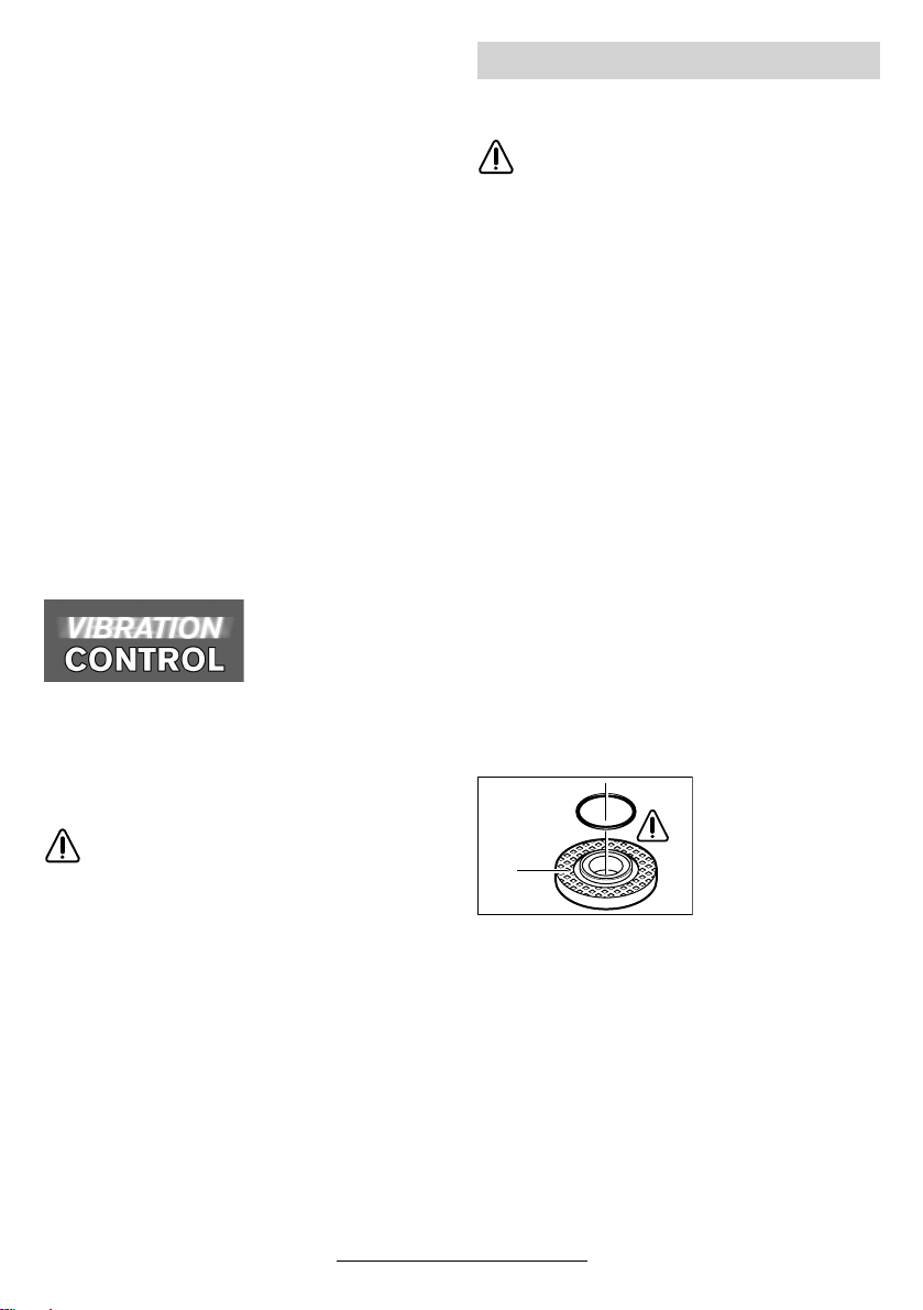
Im Aufnahmeflansch 10 ist um den
Zentrierbund ein ORing (Kunststoffteil)
10
eingesetzt.
Handschutz
Für Arbeiten mit dem Gummischleifteller 21 oder
mit der Topfbürste 24/Scheibenbürste/Fächer-
schleifscheibe ist der Handschutz 19 (Zubehör)
zu montieren. Der Handschutz 19 wird mit dem
Zusatzgriff 5 befestigt.
9 • 1 609 929 F55 • TMS • 18.12.03
Deutsch - 4
Fehlt der O-Ring oder ist er beschädigt, muss
er unbedingt ersetzt werden (Bestell-Nr.
1 600 210 039), bevor der Aufnahmeflansch 10
montiert wird.
Nach der Montage des Schleifwerkzeu-
☞
ges vor dem Einschalten prüfen, ob das
Schleifwerkzeug richtig montiert ist und
sich frei drehen kann.
Page 9
Fächerschleifscheibe
(Schleifmopteller)
Je nach Anwendung ggf. die Schutzhaube 7 abnehmen und den Handschutz 19 montieren.
Speziellen Aufnahmeflansch 10 (Zubehör, Bestell-Nr. 2 605 703 028) und die Fächerschleifscheibe auf die Schleifspindel 6 setzen. Die
Spannmutter 12 aufschrauben und mit dem
Zweilochschlüssel festziehen.
Gummi-Schleifteller 21
Je nach Anwendung ggf. die Schutzhaube 7 abnehmen und den Handschutz 19 montieren.
Bevor der Gummischleifteller 21 montiert wird,
zuerst die 2 Distanzscheiben 20 auf die Schleifspindel setzen.
Montage siehe Bildseite.
Die Rundmutter 23 aufschrauben und mit dem
Zweilochschlüssel festziehen.
Topfbürste 24/Scheibenbürste
Je nach Anwendung ggf. die Schutzhaube 7 abnehmen und den Handschutz 19 montieren.
Das Schleifwerkzeug muss sich so weit auf die
Schleifspindel 6 aufschrauben lassen, dass es
am Schleifspindelflansch am Ende des Schleifspindelgewindes fest anliegt. Mit Gabelschlüssel
festziehen.
Schleiftopf
Beim Arbeiten mit Schleiftöpfen spezielle Schutzhaube 16 verwenden.
Der Schleiftopf 17 sollte immer nur soweit aus
der Schutzhaube 16 ragen, wie dies für den jeweiligen Bearbeitungsfall unbedingt erforderlich
ist.
Die Schutzhaube 16 auf dieses Maß nachstellen.
Montage siehe Bildseite.
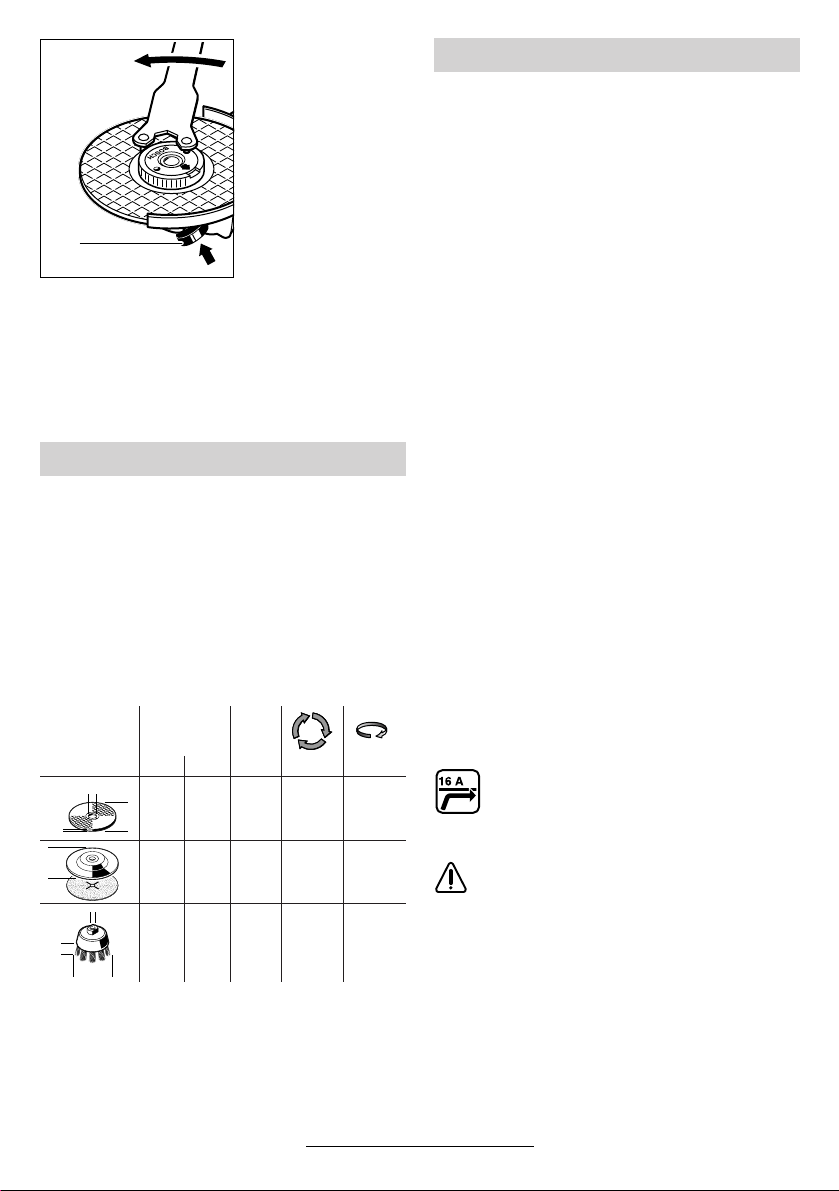
Die Spannmutter 12 aufschrauben und mit passendem gekröpftem Zweilochschlüssel 18 festziehen.
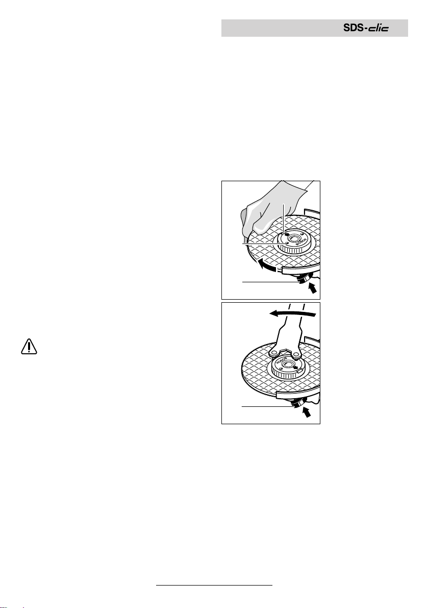
Schnellspannmutter
Anstelle der Spannmutter 12 kann die Schnellspannmutter 13 (Zubehör) verwendet werden.
Schleifwerkzeuge lassen sich dann ohne Werkzeug montieren.
Die Schnellspannmutter 13 darf nur für
Schrupp- und Trennscheiben verwendet werden.
Nur einwandfreie, unbeschädigte Schnellspannmutter 13 verwenden.
Beim Aufschrauben darauf achten, dass die
beschriftete Seite nicht zur Schleifscheibe
zeigt; der Pfeil muss auf die Indexmarke 30
zeigen.
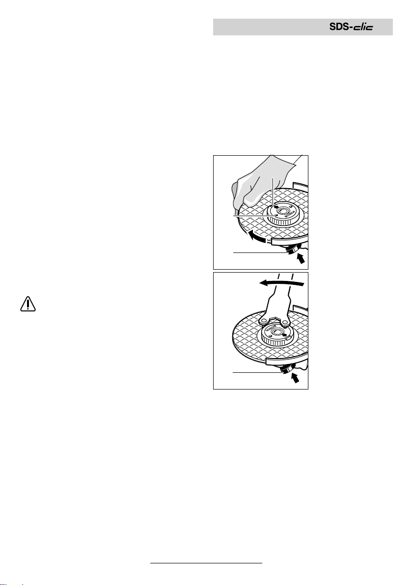
Die Schleifspindel
30
13
feststellen mit der
Spindel-Arretiertaste 2. Die Schnellspannmutter durch
kräftiges Drehen der
Schleifscheibe im
Uhrzeigersinn festziehen.
2
Eine ordnungsgemäß befestigte unbeschädigte Schnellspannmutter lässt
sich durch Drehen
des Rändelringes
entgegen dem Uhrzeigersinn von Hand
lösen.
Eine festsitzende
2
Schnellspannmutter nie mit einer
Zange lösen, sondern Zweilochschlüssel verwenden. Den Zweiloch-
schlüssel wie im Bild
gezeigt ansetzen.
10 • 1 609 929 F55 • TMS • 18.12.03
Deutsch - 5
Page 10
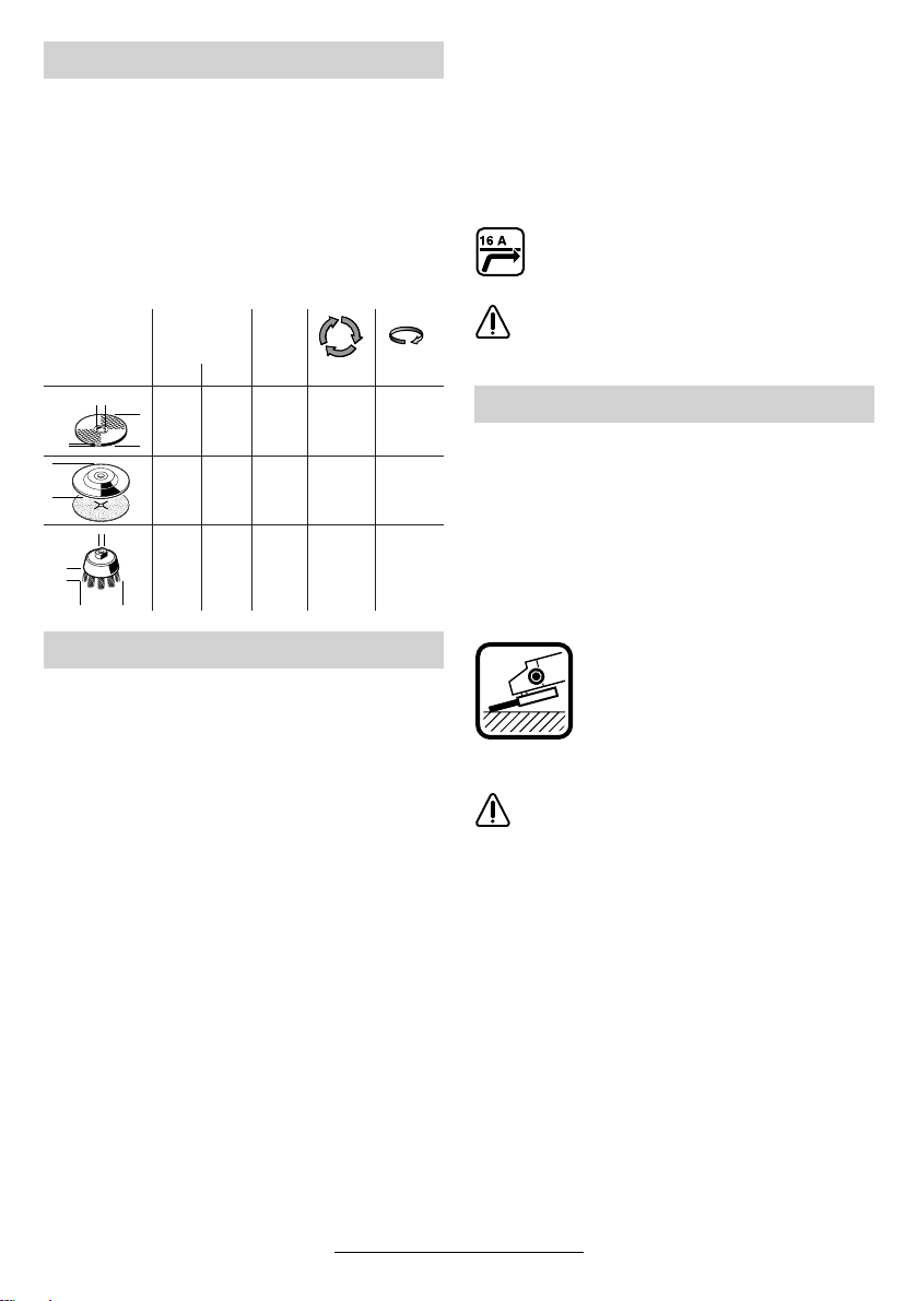
Zulässige Schleifwerkzeuge
Verwendet werden können alle in dieser Bedienungsanleitung genannten Schleifwerkzeuge.
Die zulässige Drehzahl [min
schwindigkeit [m/s] der verwendeten Schleifwerkzeuge muss den Angaben in der Tabelle
mindestens entsprechen.
Deshalb stets die zulässige Drehzahl/Um-
fangsgeschwindigkeit auf dem Etikett der
Schleifwerkzeuge beachten.
max.
[mm] [mm]
Db d[min
d
180
D
b
D
b
23088
180
230––
d
100 30 M 14 8 500 45
D
-1
] bzw. Umfangsge-
-1
] [m/s]
22,2
8 500
22,2
6 5008080
––8 500
6 5008080
Inbetriebnahme
Netzspannung beachten: Die Spannung der
Stromquelle muss mit den Angaben auf dem
Typschild des Gerätes übereinstimmen. Mit
230 V gekennzeichnete Geräte können auch an
220 V betrieben werden.
Ein-/Ausschalten
Zur Inbetriebnahme des Gerätes den Ein-/Ausschalter 3 nach vorn schieben und anschließend
drücken.
Zum Feststellen den Ein-/Ausschalter 3 in gedrücktem Zustand weiter vorschieben.
Zum Ausschalten des Gerätes den Ein-/Ausschalter 3 loslassen bzw. drücken und loslassen.
Schalterausführung ohne Arretierung
(länderspezifisch):
Zur Inbetriebnahme des Gerätes den Ein-/Ausschalter 3 nach vorn schieben und anschließend
drücken.
Zum Ausschalten des Gerätes den Ein-/Ausschalter 3 loslassen.
Probelauf!
☞
Schleifwerkzeuge vor Gebrauch überprüfen. Das Schleifwerkzeug muss einwandfrei montiert sein und sich frei drehen können. Probelauf mindestens 30 Sekunden
ohne Belastung durchführen. Beschädigte,
unrunde oder vibrierende Schleifwerkzeuge nicht verwenden.
Anlaufstrombegrenzung (Typ J)
Durch sanften Anlauf des Gerätes reicht
eine 16-A-Sicherung aus.
Ein Gerät ohne Anlaufstrombegrenzung
benötigt eine höhere Absicherung (mind.
eine träge 16-A-Sicherung einsetzen).
Arbeitshinweise
■ Das Werkstück einspannen, sofern es
nicht durch sein Eigengewicht sicher liegt.
■ Das Gerät nicht so stark belasten, dass es
zum Stillstand kommt.
■ Schrupp- und Trennscheiben werden beim
Arbeiten sehr heiß; nicht anfassen bevor
sie abgekühlt sind.
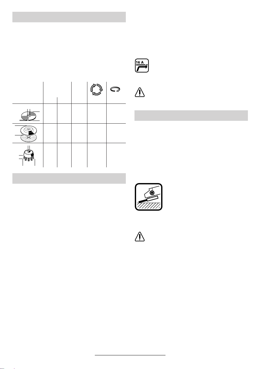
Schruppschleifen
Mit Anstellwinkeln von 30° bis 40°
erreicht man beim Schruppen das
beste Ergebnis. Gerät mit mäßigem Druck hin und her bewegen.
Dadurch wird das Werkstück nicht
zu heiß, verfärbt sich nicht, und es
gibt keine Rillen.
Niemals Trennscheiben zum Schruppen
verwenden.
Fächerschleifscheibe
(Schleifmopteller)
Mit der Fächerschleifscheibe (Zubehör) lassen
sich auch gewölbte Oberflächen und Profile
(Konturenschliff) bearbeiten.
Fächerschleifscheiben haben wesentlich höhere
Standzeiten als Schleifblätter, geringere Geräuschpegel und niedrigere Schleiftemperaturen.
11 • 1 609 929 F55 • TMS • 18.12.03
Deutsch - 6
Page 11
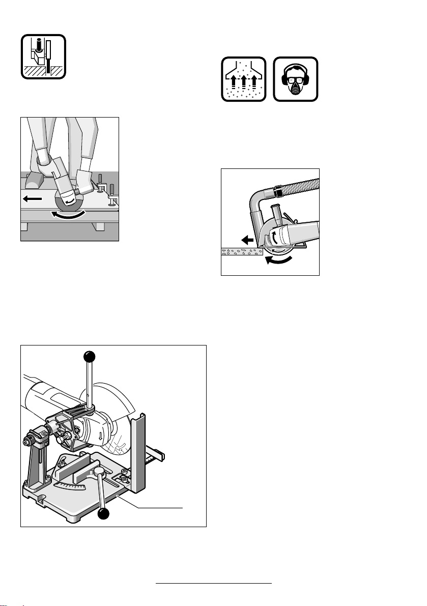
Trennschleifen
Beim Trennschleifen nicht drücken,
nicht verkanten, nicht oszillieren.
Mit mäßigem, dem zu bearbeitenden Material angepassten Vorschub arbeiten.
Auslaufende Trennschleifscheiben
nicht durch seitliches Gegendrü-
cken abbremsen.
Wichtig ist die Richtung, in die man
trennt.
Das Gerät muss
stets im Gegenlauf
arbeiten; deshalb mit
dem Gerät nicht in
die andere Richtung
fahren! Es besteht
sonst die Gefahr,
dass es unkontrol-
liert aus dem Schnitt
gedrückt wird.
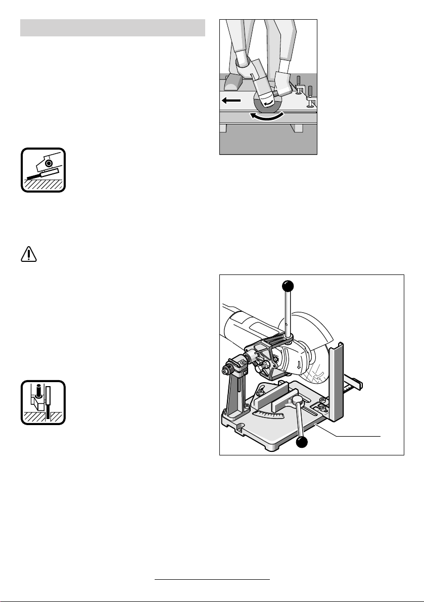
Trennschleifständer
Mit dem Trennschleifständer 29 (Zubehör) kön-
nen Werkstücke längengleich im Winkel von
0 bis 45° zugeschnitten werden.
Die Sicherheits- und Arbeitshinweise in der entsprechenden Bedienungsanleitung des Trennschleifständers sind strikt zu beachten. Nur Original Bosch Trennschleifständer verwenden.
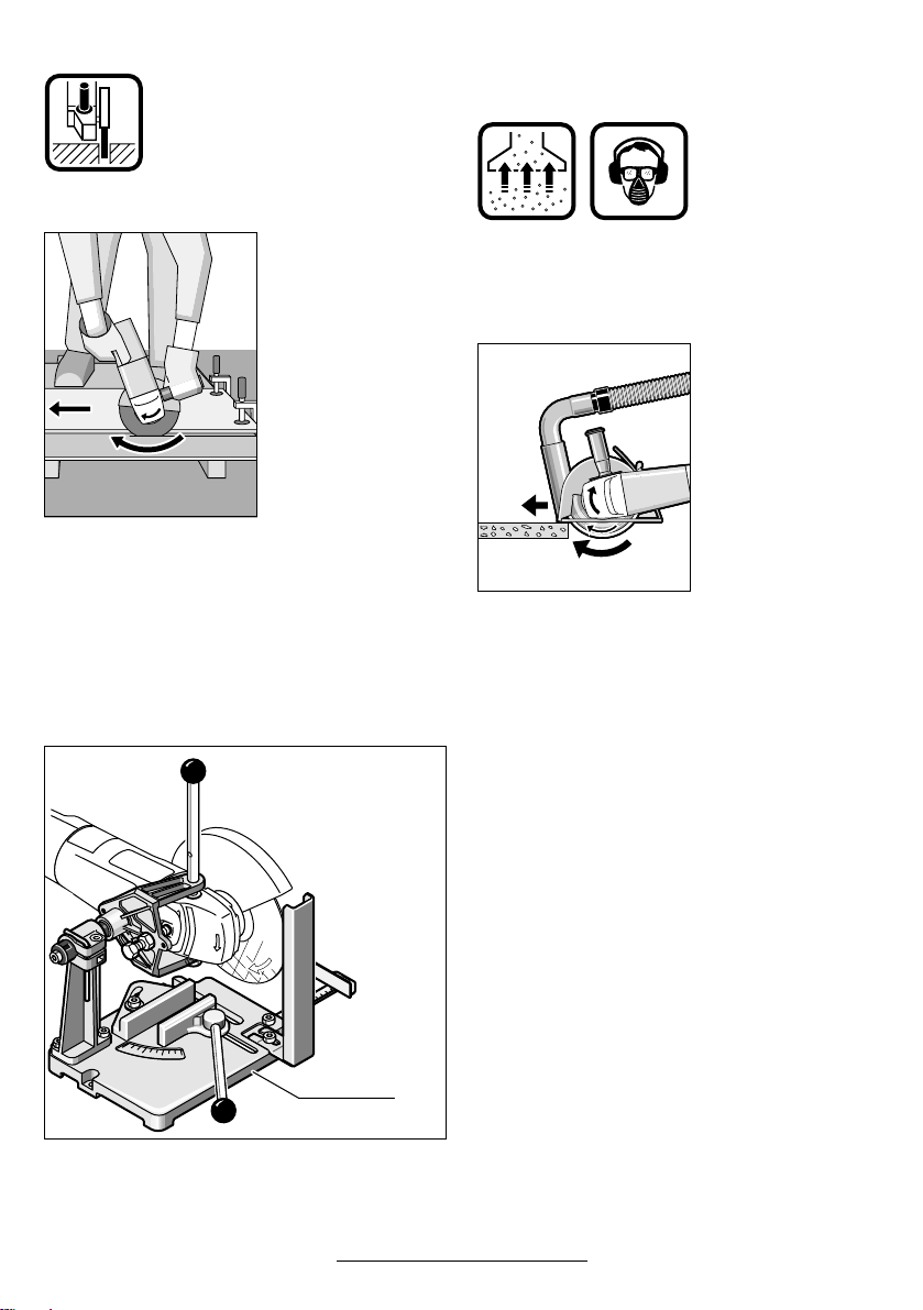
Trennen von Gestein
■ Das Gerät darf nur für Trockenschnitt/Trockenschliff verwendet werden.
Am besten eine Diamant-Trennscheibe
verwenden. Zur Sicherheit gegen Verkanten den Füh-
rungsschlitten 26
mit spezieller Absaugschutzhaube
benutzen.
Das Gerät nur mit Staubabsaugung betreiben.
Zusätzlich Staubschutzmaske tragen.
Der Staubsauger
muss zum Absaugen
von Gesteinsstaub
zugelassen sein.
Bosch bietet geeignete Staubsauger an.
Das Gerät einschalten
und mit dem vorderen
Teil des Führungsschlittens auf das
Werkstück setzen.
Das Gerät mit mäßigem, dem zu bearbeitenden
Material angepassten Vorschub schieben (Bild).
Beim Trennen besonders harter Werkstoffe, z. B.
Beton mit hohem Kieselgehalt, kann die Diamant-Trennscheibe überhitzen und dadurch beschädigt werden. Ein mit der Diamant-Trennscheibe umlaufender Funkenkranz weist deutlich
darauf hin.
In diesem Fall den Trennvorgang unterbrechen
und die Diamant-Trennscheibe kurze Zeit unbelastet bei Leerlaufdrehzahl abkühlen lassen.
Merklich nachlassender Arbeitsfortschritt und
umlaufender Funkenkranz sind Anzeichen für
eine stumpf gewordene Diamant-Trennscheibe.
Durch kurze Schnitte in abrasivem Material (z. B.
Kalksandstein) kann diese wieder geschärft werden.
12 • 1 609 929 F55 • TMS • 18.12.03
29
Deutsch - 7
Page 12
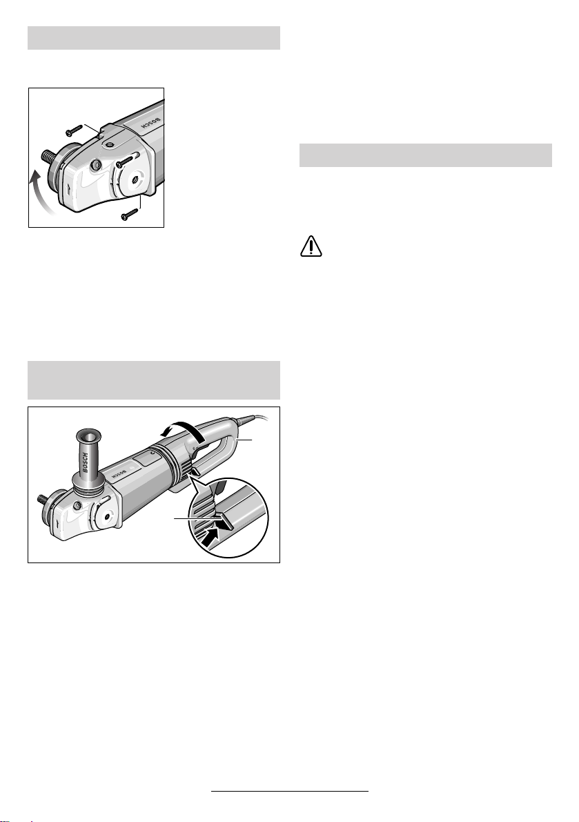
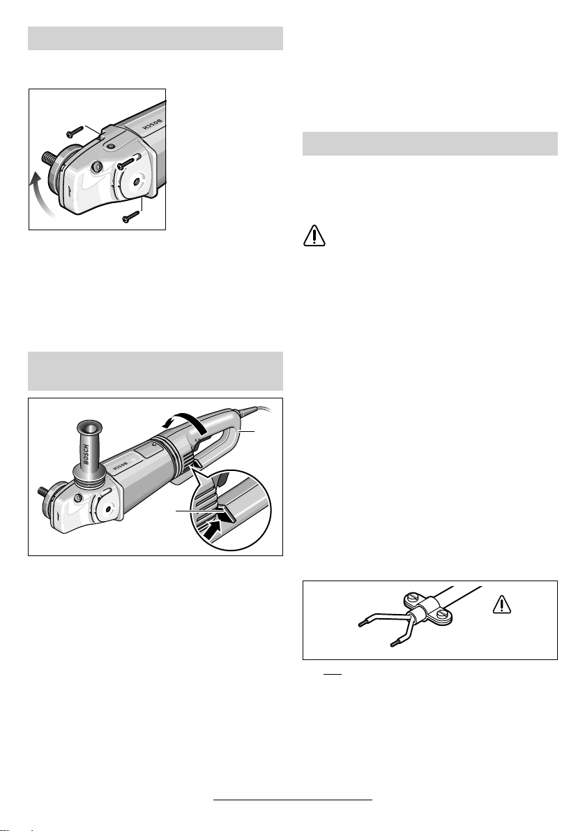
Gerätekopf drehen
■ Vor allen Arbeiten am Gerät Netzstecker
ziehen.
Der Gerätekopf lässt
sich zum Gerätege-
häuse in 90°-Schritten drehen. Dadurch
kann der Ein-/Ausschalter für besondere Arbeitsfälle in
eine günstigere
Handhabungsposition gebracht werden; z. B. für Trenn-
rungsschlitten 26/Trennschleifständer 29
(Zubehör) oder für Linkshänder.
Die vier Schrauben ganz herausdrehen.
Den Gerätekopf vorsichtig und ohne vom Ge-
häuse abzunehmen in die neue Position drehen.
Die Schrauben wieder eindrehen und festziehen.
arbeiten mit Füh-
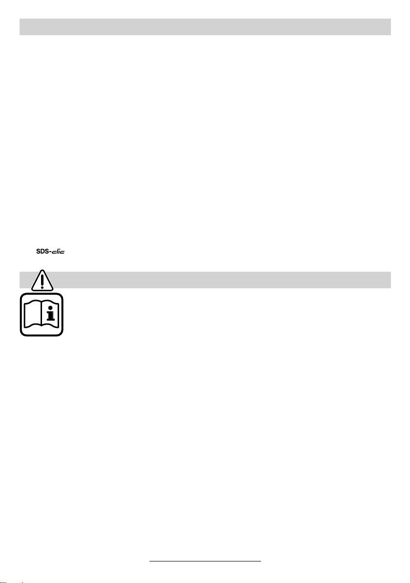
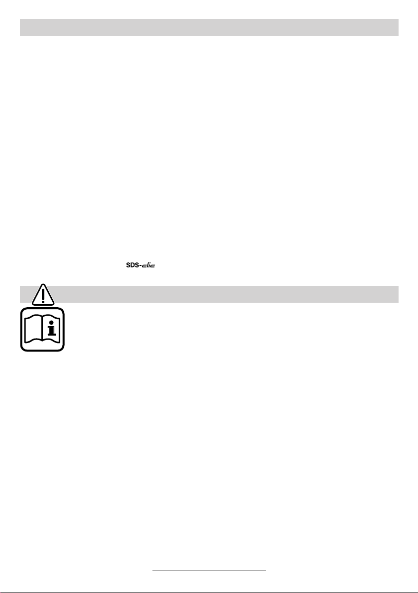
Gerätegriff drehen
(GWS 24/26-180/230 (J)BV)
➋
28
27
➊
Der Griff 28 lässt sich zum Motorgehäuse jeweils
um 90° nach links und nach rechts drehen. Dadurch kann der Ein-/Ausschalter für besondere
Arbeitsfälle in eine günstigere Handhabungsposition gebracht werden; z. B. für Trennarbeiten
mit Führungsschlitten/Trennschleifständer (Zubehör) und für Linkshänder.
Die Griffentriegelung 27 kräftig in Pfeilrichtung
➊) und gleichzeitig den Griff 28 in die ge-
ziehen (
wünschte Position drehen (
Die Abbildung zeigt den Griff 28 um 90° gedreht.
➋) bis er einrastet.
Die Griffentriegelung 27 und der Ein-/Aus-
☞
schalter 3 haben eine Sicherheitsverriegelung.
Das Gerät kann nicht eingeschaltet werden, solange der Griff 28 nicht in einer der
drei möglichen Positionen eingerastet ist.
Der Griff 28 lässt sich nicht entriegeln,
wenn der Ein-/Ausschalter 3 arretiert ist.
Wartung und Reinigung
■ Vor allen Arbeiten am Gerät Netzstecker
ziehen.
Gerät und Lüftungsschlitze stets sauber
☞
halten, um gut und sicher zu arbeiten.
Bei extremen Einsatzbedingungen kann
sich bei der Bearbeitung von Metallen leitfähiger Staub im Innern des Gerätes absetzen. Die Schutzisolierung des Gerätes
kann beeinträchtigt werden. Es empfiehlt
sich in solchen Fällen die Verwendung einer stationären Absauganlage, häufiges
Ausblasen der Lüftungsschlitze und das
Vorschalten eines Fehlerstrom-Schutzschalters (FI).
Wenn die schwingungsdämpfenden Elemente an
der Vibrationsdämpfung 4 beschädigt sind, z. B.
eingerissen, muss das Gerät zur Wartung an den
Kundendienst geschickt werden (Anschrift siehe
Abschnitt „Service und Kundenberater“).
Sollte das Gerät trotz sorgfältiger Herstellungsund Prüfverfahren einmal ausfallen, ist die Reparatur von einer autorisierten Kundendienststelle
für Bosch-Elektrowerkzeuge ausführen zu lassen.
Bei allen Rückfragen und Ersatzteilbestellungen
bitte unbedingt die 10-stellige Bestellnummer laut
Typenschild des Gerätes angeben.
13 • 1 609 929 F55 • TMS • 18.12.03
Deutsch - 8
Page 13

Umweltschutz Service und Kundenberater
Explosionszeichnungen und Informationen
zu Ersatzteilen finden Sie unter:
www.bosch-pt.com
www.powertool-portal.de, das Internetportal
für Handwerker und Heimwerker
Rohstoffrückgewinnung statt Müllentsorgung
Gerät, Zubehör und Verpackung sollten einer
umweltgerechten Wiederverwertung zugeführt
werden.
Diese Anleitung ist aus chlorfrei gefertigtem Recycling-Papier hergestellt.
Zum sortenreinen Recycling sind Kunststoffteile
gekennzeichnet.
In Deutschland sind nicht mehr gebrauchsfähige
Geräte zum Recycling beim Handel abzugeben
oder (ausreichend frankiert) direkt einzuschicken
an:
Recyclingzentrum Elektrowerkzeuge
Osteroder Landstraße 3
37589 Kalefeld
www.ewbc.de, der Informations-Pool für Hand-
werk und Ausbildung
Deutschland
Robert Bosch GmbH
Servicezentrum Elektrowerkzeuge
Zur Luhne 2
37589 Kalefeld
✆ Service: ....................................... 01 80 - 3 35 54 99
........................................... +49 (0) 55 53 / 20 22 37
Fax:
✆ Kundenberater: ...................... 01 80 - 3 33 57 99
Österreich
ABE Service GmbH
Jochen-Rindt-Straße 1
1232 Wien
✆ Service: ..................................... +43 (0)1 / 61 03 80
............................................... +43 (0)1 / 61 03 84 91
Fax:
✆ Kundenberater:............ +43 (0)1 / 797 22 3066
E-Mail: abe@abe-service.co.at
Schweiz
✆ Service: ................................. +41 (0)1 / 8 47 16 16
.................................................. +41 (0)1 / 8 47 16 57
Fax:
✆ Kundenberater............................... 0 800 55 11 55
14 • 1 609 929 F55 • TMS • 18.12.03
Konformitätserklärung
Wir erklären in alleiniger Verantwortung, dass
dieses Produkt mit den folgenden Normen oder
normativen Dokumenten übereinstimmt:
EN 50 144 gemäß den Bestimmungen der Richtlinien 89/336/EWG, 98/37/EG.
Dr. Egbert Schneider Dr. Eckerhard Strötgen
Senior Vice President Head of Product
Engineering Certification
Robert Bosch GmbH, Geschäftsbereich Elektrowerkzeuge
Änderungen vorbehalten
Deutsch - 9
Page 14

Tool Specifications
Angle Grinder GWS 21-180 HV
PROFESSIONAL
GWS 21-230 HV
PROFESSIONAL
GWS 24-180 BV
PROFESSIONAL
Order number 0 601 851 B.. 0 601 852 B.. 0 601 853 B..
With residual current-limit control GWS 21-180 JHV
PROFESSIONAL
GWS 21-230 JHV
PROFESSIONAL
GWS 24-180 JBV
PROFESSIONAL
Order number 0 601 851 G.. 0 601 852 G.. 0 601 853 G..
Rated input power* [W] 2 100 2 100 2 400
Output power [W] 1 350 1 350 1 700
No-load speed [rpm] 8 500 6 500 8 500
Grinding disc dia., max. [mm] 180 230 180
Grinder spindle thread M 14 M 14 M 14
Weight without cable, approx. [kg] 4.4 4.4 5.2
Protection class / II / II / II
Angle Grinder GWS 24-230 BV
PROFESSIONAL
GWS 26-180 BV
PROFESSIONAL
GWS 26-230 BV
PROFESSIONAL
Order number 0 601 854 B.. 0 601 855 B.. 0 601 856 B..
With residual current-limit control GWS 24-230 JBV
PROFESSIONAL
GWS 26-180 JBV
PROFESSIONAL
GWS 26-230 JBV
PROFESSIONAL
Order number 0 601 854 G.. 0 601 855 G.. 0 601 856 G..
Rated input power* [W] 2 400 2 600 2 600
Output power [W] 1 700 1 800 1 800
No-load speed [rpm] 6 500 8 500 6 500
Grinding disc dia., max. [mm] 230 180 230
Grinder spindle thread M 14 M 14 M 14
Weight without cable, approx. [kg] 5.2 5.2 5.2
Protection class / II / II / II
Please observe the order number of your machine. The trade names of the individual machines may vary.
Inrush currents cause short-time voltage drops. Under unfavourable power supply conditions, other equipment may be
affected. If the system impedance of the power supply is lower than 0.25 Ohm, disturbances are unlikely to occur.
* The values given are valid for nominal voltages [U] of 230/240 V. For lower voltages and models for specific countries,
these values can vary.
Intended Use
The machine is intended for cutting, roughing and
brushing metal and stone materials without using
water. For cutting stone, a cutting guide is required.
Information on Structures
Slots in structural walls are subject to the Standard DIN 1053, Part 1 or country-specific regulations.
These regulations are to be observed under all
circumstances. Before beginning work, consult
the responsible structural engineer, architects or
the construction supervisor.
15 • 1 609 929 F55 • TMS • 18.12.03
English - 1
Noise/Vibration Information
Measured values determined according to
EN 50 144.
Typically the A-weighted noise levels of the machine are: Sound pressure level: 90 dB (A);
sound power level: 103 dB (A).
Wear hearing protection!
The typical hand/arm vibration is below 2.5 m/s
(1.7 m/s2).
2
Page 15
Machine Elements
The numbering of the device elements refers to
the illustration of the machine on the graphics
page.
While reading the operating instructions, unfold
the graphics page for the device and leave it
open.
1 Thread for auxiliary handle (3x)
2 Spindle lock button
3 On/Off switch
4 Vibration damper
5 Auxiliary handle
6 Grinder spindle
7 Protection guard
8 Adjustment screw
9 Clamping lever
10 Mounting flange with O-ring
11 Grinding/cutting disc*
12 Clamping nut
13 quick-clamping nut*
For Your Safety
Working safely with this machine is possible only when the
operating and safety information
are read completely and the instructions contained therein are
strictly followed. In addition, the
general safety notes in the enclosed booklet
must be observed. Before using for the first
time, ask for a practical demonstration.
■ Wear protective glasses and hearing protec-
tion.
■ Wear additional protection equipment for your
safety, such as protective gloves, sturdy
shoes, hard hat and apron.
■ The dust that is produced while working can be
detrimental to health, inflammable or explosive. Suitable safety measures are required.
Examples: Some dusts are regarded as carcinogenic. Use suitable dust/chip extraction and
wear a dust respirator.
■ Dust from light alloys can burn or explode. Al-
ways keep the workplace clean, as blends of
materials are particularly dangerous.
14 Clamping screw
15 Coded projection
16 Guard, grinding cup*
17 Grinding cup*
18 Two-pin spanner for clamping nut*
19 Hand guard*
20 Spacer discs*
21 Rubber sanding plate*
22 Sanding sheet*
23 Round nut*
24 Cup brush*
25 Diamond cutting disc*
26 Cutting guide with dust extraction protection
guard*
27 Handle unlocking button
28 Handle
29 Cutting grinder stand*
* Not all of the accessories illustrated or described are
included as standard delivery.
■ If the mains cable is damaged or cut through
while working, do not touch the cable but immediately pull the mains plug. Never use the
machine with a damaged cable.
■ Connect machines that are used in the open
via a residual current device (RCD) with an actuating current of 30 mA maximum. Do not operate the machine in rain or moisture.
■ When working with the machine, always hold it
firmly with both hands and provide for a secure
stance.
■ Secure the workpiece. A workpiece clamped
with clamping devices or in a vice is held more
secure than by hand.
■ Always direct the cable to the rear away from
the machine.
■ Always switch the machine off and wait until it
has come to a standstill before placing it down.
■ For power outage or when the mains plug is
pulled, unlock the On/Off switch immediately
and turn it to the off position. This prevents uncontrolled restarting.
■ The machine must be used only for dry cutting/
grinding.
16 • 1 609 929 F55 • TMS • 18.12.03
English - 2
Page 16

■ For all work with the machine, the auxiliary
handle must be mounted.
■ Hold the power tool only by the insulated
gripping surfaces, when performing an operation where the cutting tool may run into
hidden wiring or its own cord.
Contact with a “live” wire will make exposed
metal parts of the tool “live” and shock the operator.
■ Use appropriate detectors to determine if
utility lines are hidden in the work area or
call the local utility company for assistance.
Contact with electric lines can lead to fire and
electric shock. Damaging a gas line can lead
to explosion. Penetrating a water line causes
property damage or may cause an electric
shock.
■ For work with grinding or cutting discs, the protection guard 7 must be mounted. For work
with the rubber sanding plate 21 or with the
cup brush 24/disc brush/flap disc, the hand
guard 19 (accessory) is to be mounted.
■ Use dust extraction when working with stone.
The vacuum cleaner must be approved for masonry dust. When cutting stone, use the cutting
guide.
■ Do not work with materials containing asbestos.
■ Use only grinding tools with a permissible
speed at least as high as the no-load speed of
the machine.
■ Check grinding tools before use. The grinding
tool must be properly mounted and turn freely.
Perform a test run for at least 30 seconds without load. Do not use damaged, out-of-round or
vibrating grinding tools.
■ Protect the grinding tool from impact, shock
and grease.
■ Apply the machine to the workpiece only when
switched on.
■ Keep hands away from rotating grinding tools.
■ Pay attention to the direction of rotation. Al-
ways hold the machine so that sparks and
grinding dust fly away from the body.
■ When grinding metal, flying sparks are produced. Take care that no persons are endangered. Due to danger of fire, no combustible
materials should be located in the vicinity
(spark flight zone).
■ Be careful when cutting grooves, e. g. in structural walls: See Information on Structures.
■ Blocking the cutting disc leads to jerking reaction forces on the machine. In this case switch
off the machine immediately.
■ Pay attention to the dimensions of the grinding
disc. The mounting hole diameter must fit the
mounting flange 10 without play. Do not use
reducers or adapters.
■ Never use cutting discs for rough grinding. Do
not exert any lateral pressure on the cutting
discs.
■ Observe the manufacturer’s instructions for
mounting and using grinding tools.
■ Caution! The grinding tool runs on after the
machine is switched off.
■ Do not clamp the machine in a vice.
■ Never allow children to use the machine.
■ Bosch is only able to ensure perfect operation
of the machine if the original accessories intended for it are used.
Mounting the
Protective Devices
■ Before any work on the machine itself, pull
the mains plug.
■ For work with grinding or cutting discs, the
protection guard 7 must be mounted.
Protection Guard with Locking Screw
The coded projection 15 on the protection
guard 7 ensures that only a guard that fits the
machine type can be mounted.
Loosen the clamping screw 14, if necessary.
Place the protection guard 7 with coded projec-
tion 15 into the coded groove on the spindle collar of the machine head and rotate to the required
position (working position).
The closed side of the protection guard 7
must always point to the operator.
Tighten clamping screw 14.
17 • 1 609 929 F55 • TMS • 18.12.03
English - 3
Page 17
Protection Guard with Quick Clamp
The protection guard is preadjusted to the
☞
diameter of the spindle collar. If required,
the tightening tension of the clamping
bracket can be changed by tightening or
loosening the adjustment screw 8. Always
ensure that the protection guard 7 is
seated tightly on the spindle collar.
Open the clamping lever 9.
Place the protection guard 7 on the spindle collar
of the machine head and turn to the required position (working position).
To fasten the protection guard 7, close the
clamping lever 9.
The closed side of the protection guard 7
must always point to the operator.
Auxiliary Handle
■ For all work with the machine, the auxiliary
handle must be mounted.
Screw the auxiliary handle 5 into the head of the
machine according to the working method.
Vibration Damping
The integrated vibration damper 4 and the vibration-dampening auxiliary handle reduce occurring vibrations to below 2.5 m/s
EN 50 144, and enable vibrational-reduced and
thus more agreeable and secure working.
Do not make any alterations to the vibration damper 4 and the auxiliary handle. Do not continue to use damaged
parts.
2
according to
Mounting the Grinding Tools
■ Before any work on the machine itself, pull
the mains plug.
Use only grinding tools with a permissible speed at least as high as the no-load
speed of the machine.
Grinding and cutting discs become very
hot while working; do not touch until
they have cooled.
■ Clean the grinder spindle and all parts to be
mounted. For clamping and loosening the
grinding tools, lock the grinder spindle 6 with
the spindle lock button 2.
Actuate the spindle lock button 2 only when
the grinder spindle is at a standstill!
Grinding/Cutting Disc
Pay attention to the dimensions of the grinding
disc. The mounting hole diameter must fit the
mounting flange 10 without play. Do not use reducers or adapters.
When using a diamond cutting disc, take care
that the direction-of-rotation arrow on the diamond cutting disc and the direction of rotation of
the machine (direction-of-rotation arrow on the
machine head) agree.
For mounting, see the illustration page.
Screw on the clamping nut 12 and tighten with
the two-pin spanner (see Section “Quick-clamp-
ing Nut”).
An O-ring (plastic
part) is inserted in
the mounting
flange 10 around the
10
spigot.
Hand Guard
For work with the rubber sanding plate 21 or with
the cup brush 24/disc brush/flap disc, the hand
guard 19 (accessory) is to be mounted. The hand
guard 19 is fastened with the auxiliary handle 5.
18 • 1 609 929 F55 • TMS • 18.12.03
English - 4
If the O-ring is missing or is damaged, it must
in all cases be replaced (Order No.
1 600 210 039) before the mounting flange 10 is
mounted.
After mounting the grinding tool and be-
☞
fore switching on, check that the grinding tool is correctly mounted and that it
can turn freely.
Page 18
Flap Disc
Depending on the application, remove the protection guard 7 and mount the hand guard 19. Place
the special mounting flange 10 (accessory, Order
No. 2 605 703 028) and the flap disc on the
grinder spindle 6. Screw on the clamping nut 12
and tighten with the two-pin spanner.
Rubber Sanding Plate 21
Depending on the application, remove the protection guard 7 and mount the hand guard 19.
Before mounting the rubber sanding pad 21,
place the 2 spacers 20 onto the grinding spindle.
For mounting, see the illustration page.
Screw on the round nut 23 and tighten with the
two-pin spanner.
Cup Brush 24/Disc Brush
Depending on the application, remove the protection guard 7 and mount the hand guard 19.
The grinding tool must be able to be screwed
onto the grinding spindle 6 until it rests firmly
against the grinder spindle flange at the end of
the grinder spindle threads. Tighten with an
open-end spanner.
Grinding Cup
When working with grinding cups, use
the special guard 16.
The grinding cup 17 should always protrude
from the guard 16 only as far as absolutely necessary for the work to be performed in each case.
Adjust the guard 16 to this distance.
For mounting, see the illustration page.
Screw on the clamping nut 12 and tighten with
the fitting offset two-pin spanner 18.
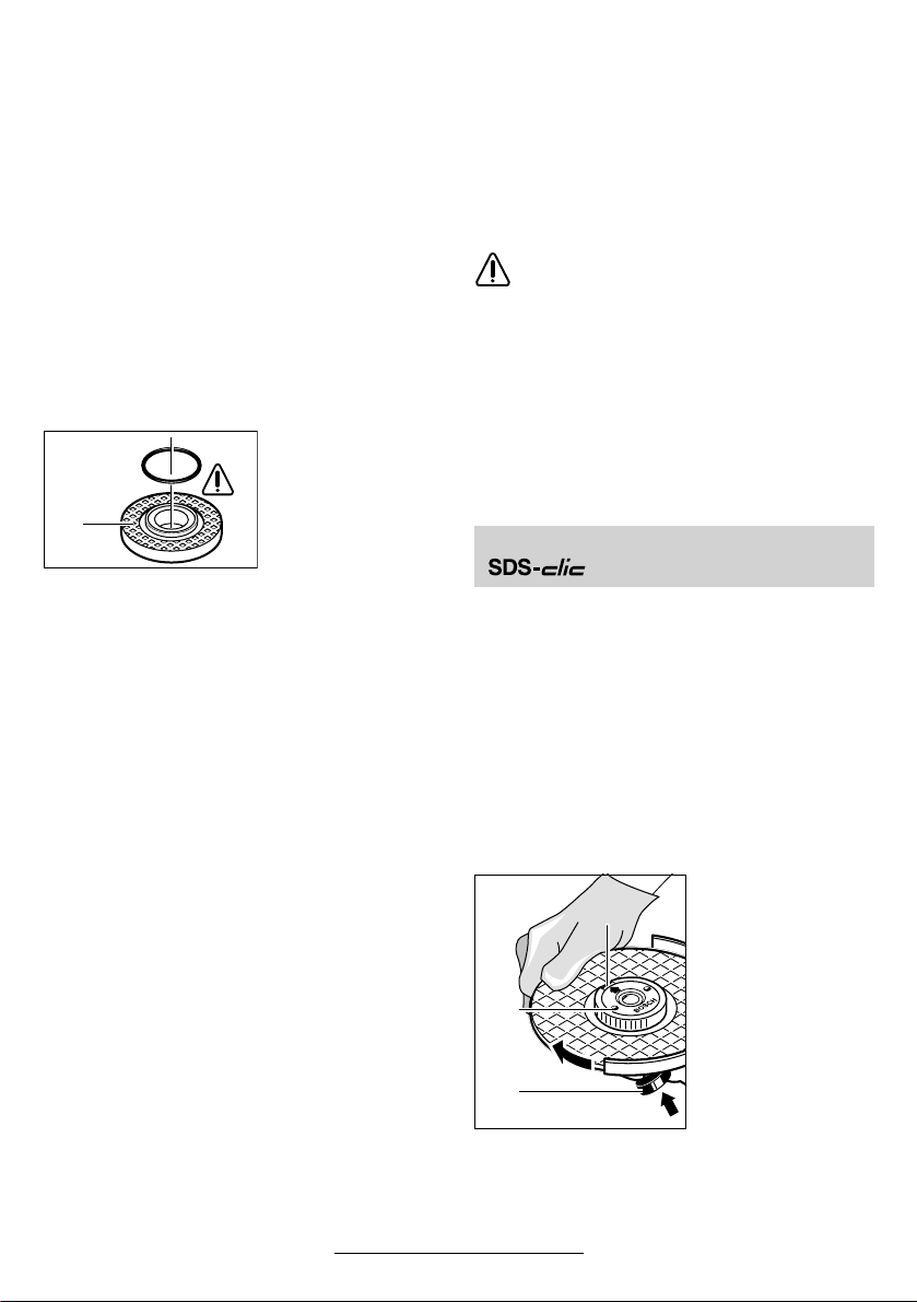
Quick Clamping Nut
Instead of the clamping nut 12, the quick-clamping nut 13 (accessory) can be used. Grinding
tools can then be mounted without using tools.
The quick-clamping nut 13 may be used only
for grinding and cutting discs.
Use only a flawless, undamaged quick-clamping nut 13.
When screwing on, take care that the side
with printing does not point to the grinding
disc. The arrow must point to the index
mark 30.
Lock the grinder
30
13
spindle with the spindle lock button 2.
Tighten the quickclamping nut by
forcefully turning the
grinding disc in the
clockwise direction.
2
A properly tightened
undamaged, quickclamping nut can be
loosened by hand
turning the knurled
ring in anticlockwise
direction.
Never loosen a tight
quick-clamping nut
with pliers but use a
2
two-pin spanner. In-
sert the two-pin
spanner as shown in
the illustration.
19 • 1 609 929 F55 • TMS • 18.12.03
English - 5
Page 19
Approved Grinding Tools
All grinding tools mentioned in this operating
manual instruction can be used.
The permissible speed [rpm] or the circumferential speed [m/s] of the grinding tools used must at
least match the values given in the table.
Therefore, always observe the permissible
rotational/circumferential speed on the label
of the grinding tool.
max.
[mm] [mm]
Db d[rpm] [m/s]
d
180
D
b
D
b
23088
180
230––––
d
100 30 M 14 8 500 45
D
22.2
22.2
8 500
6 5008080
8 500
6 5008080
Test run!
☞
Check the grinding tool before use. The
grinding tool must be properly mounted
and rotate freely. Perform a test run of at
least 30 seconds without load. Do not use
damaged, out-of-round or vibrating grinding tools.
Reduced Starting Current
(Type J)
As a result of soft starting, a 13 A fuse is
adequate.
A machine without reduced starting current
requires higher fuse protection (use at least
a 13 A time-delay fuse).
Operating Instructions
■ Clamp the workpiece if it does not remain
stationary due to its own weight.
■ Do not strain the machine so heavily that it
comes to a standstill.
■ Grinding and cutting discs become very
hot while working; do not touch until they
have cooled.
Starting Operation
Observe correct mains voltage: The voltage of
the power source must agree with the voltage
specified on the nameplate of the machine.
Equipment marked with 230 V can also be connected to 220 V.
Switching On and Off
To start the machine, press the On/Off switch 3
forward and then down.
To lock-on, push the pressed On/Off switch 3
further forwards.
To switch off the machine, release the On/Off
switch 3 or push and release it then.
Switch version without lock
(country-specific):
To start the machine, press the On/Off switch 3
forward and then down.
To switch off the machine, release the On/Off
switch 3.
Rough Grinding
The best roughing results are
achieved when setting the machine
at an angle of 30° to 40°. Move the
machine back and forth with moderate pressure. In this manner, the
workpiece will not become too hot,
does not discolour and no grooves
are formed.
Never use a cutting disc for roughing.
Flap Disc
With the flap disc (accessory), curved surfaces
and profiles (contour sanding) can be worked.
Flap discs have a considerably higher service life
than sanding sheets, lower noise level and lower
sanding temperatures.
20 • 1 609 929 F55 • TMS • 18.12.03
English - 6
Page 20
Cutting
When cutting, do not press, jam or
oscillate the machine. Work with
moderate feed, adapted to the material being machined.
Do not reduce the speed of running
down cutting discs by applying
sideward pressure.
The direction in
which the cutting is
performed is important.
The machine must
always work in an
up-grinding motion.
Therefore, never
move the machine in
the other direction!
Otherwise, the danger exists of it being
pushed uncon-
trolled out of the cut.
Grinder Stand
With the grinder stand 29 (accessory), workpieces can be cut at angles of 0 to 45° at the
same lengths.
The safety notes and operating instructions in the
respective operating instructions manual of the
angle grinder are to be strictly observed. Use only
original Bosch grinder stands.
Cutting Stone
■ The machine must be used only for dry
cutting/grinding.
It is best to use a diamond cutting disc. As
a safety measure
against jamming, use
the cutting guide 26
with the special dust
extraction protection
guard.
Operate the machine with dust extraction only. In
addition, wear a dust mask.
The vacuum cleaner
must be approved for
the extraction of masonry dust.
Bosch provides suitable vacuum cleaners.
Switch on the machine and place the
front part of the cutting guide on the
workpiece.
Slide the machine with moderate feed, adapted
to the material to be worked (Figure).
For cutting especially hard material, e. g., concrete with high pebble content, the diamond cutting disc can overheat and become damaged as
a result. This is clearly indicated by circular
sparking, rotating with the diamond cutting disc.
In this case, interrupt the cutting process and allow the diamond cutting disc to cool by running
freely at no-load speed for a short time.
Noticeable decreasing work progress and circular sparking are indications of a diamond cutting
disc that has become dull. Briefly cutting into
abrasive material (e. g., lime-sand brick) can resharpen the disc.
21 • 1 609 929 F55 • TMS • 18.12.03
29
English - 7
Page 21
Rotating the Machine Head
■ Before any work on the machine itself, pull
the mains plug.
The machine head
can be rotated with
respect to the machine housing in 90°
steps. In this manner, the On/Off
switch can be
brought to an advantageous handling
position for special
working situations,
with the cutting guide 26/cutting grinder stand 29
(accessory) or for left-handed persons.
Unscrew completely the four screws.
Rotate the machine head carefully and without
removing from the housing to the new position.
Screw in the screws again and tighten.
e. g., for cutting work
Turning the Machine Handle
(GWS 24/26-180/230 (J)BV)
➋
28
27
➊
The handle 28 can be turned with respect to the
motor housing by 90° either to the left or right.
This allows for the On/Off switch to be positioned
more conveniently for certain working situations,
e. g., for cutting work with the cutting guide/
grinder stand (accessories) and for left-handers.
Pull the handle unlocking button 27 firmly in the
direction of the arrow (
at the same time to the desired position (
it engages. The figure shows the handle 28
turned by 90°.
➊), turning the handle 28
➋) until
The handle unlocking button 27 and the
☞
On/Off switch 3 have a safety interlock.
The machine cannot be switched on if the
handle 28 is not engaged in one of the
three possible positions.
The handle 28 cannot be unlocked if the
On/Off switch 3 is locked.
Maintenance and Cleaning
■ Before any work on the machine itself, pull
the mains plug.
For safe and proper working, always keep
☞
the machine and the ventilation slots clean.
In extreme working conditions, conductive
dust can accumulate in the interior of the
machine when working with metal. The
protective insulation of the machine can be
degraded. The use of a stationary extraction system is recommended in such cases
as well as frequently blowing out the ventilation slots and installing a residual current
device (RCD).
When the vibration-dampening elements of the
vibration damper 4 are damaged, e. g., torn in,
then the machine must be sent to an after-sales
service agent for maintenance (for address, see
section “Service and Customer Assistance”).
If the machine should fail despite the care taken
in manufacturing and testing procedures, repair
should be carried out by an after-sales service
centre for Bosch power tools.
In all correspondence and spare parts orders,
please always include the 10-digit order number
given on the nameplate of the machine.
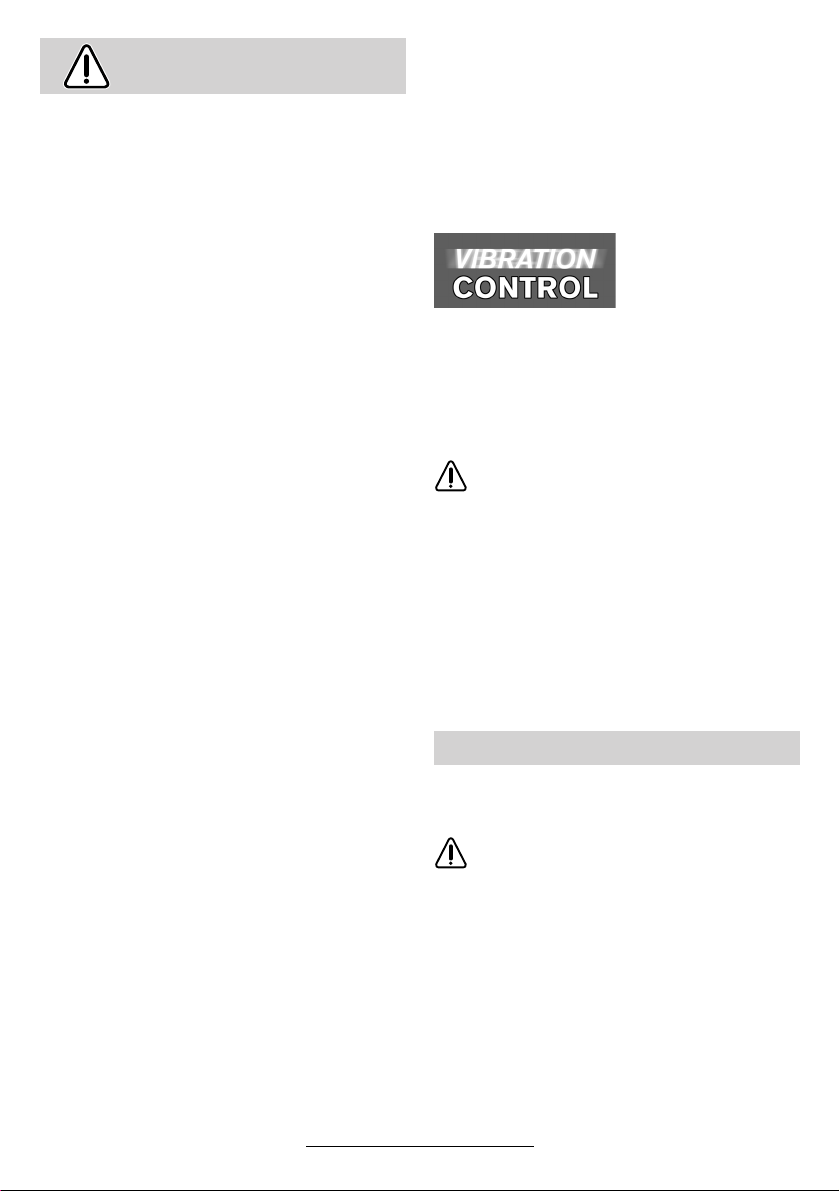
WARNING! Important instructions for connecting a new 3-pin plug to the 2-wire cable.
The wires in the cable are coloured according to
the following code:
strain relief
To be fitted
live = brown
neutral = blue
connect the blue or brown wire to the
Do not
earth terminal of the plug.
Important: If for any reason the moulded plug is
removed from the cable of this machine, it must
be disposed of safely.
by qualified
professional only
22 • 1 609 929 F55 • TMS • 18.12.03
English - 8
Page 22

Environmental Protection
Recycle raw materials instead of disposing as
waste
The machine, accessories and packaging should
be sorted for environmental-friendly recycling.
These instructions are printed on recycled paper
manufactured without chlorine.
The plastic components are labelled for categorized recycling.
Service and Customer
Assistance
Exploded views and information on spare
parts can be found under:
www.bosch-pt.com
Great Britain
Robert Bosch Ltd. (B.S.C.)
P.O. Box 98
Broadwater Park
North Orbital Road
Denham-Uxbridge
Middlesex UB 9 5HJ
✆ Service............................ +44 (0)18 95 / 83 87 82
✆ Advice line .................... +44 (0) 18 95 / 83 87 91
............................................. +44 (0) 18 95 / 83 87 89
Fax
Australia
Robert Bosch Australia Ltd.
RBAU/SPT2
1555 Centre Road
P.O. Box 66 Clayton
3168 Clayton/Victoria
✆ ............................................... +61 (0)1 / 800 804 777
............................................... +61 (0)1 / 800 819 520
Fax
www.bosch.com.au
E-Mail: CustomerSupportSPT@au.bosch.com
New Zealand
Robert Bosch Limited
14-16 Constellation Drive
Mairangi Bay
Auckland
New Zealand
✆ ..................................................... +64 (0)9 / 47 86 158
..................................................... +64 (0)9 / 47 82 914
Fax
Ireland
Beaver Distribution Ltd.
Greenhills Road
Tallaght-Dublin 24
✆ Service................................... +353 (0)1 / 414 9400
.................................................... +353 (0)1 / 459 8030
Fax
23 • 1 609 929 F55 • TMS • 18.12.03
English - 9
Declaration of Conformity
We declare under our sole responsibility that this
product is in conformity with the following standards or standardization documents: EN 50 144
according to the provisions of the directives
89/336/EEC, 98/37/EC.
Dr. Egbert Schneider Dr. Eckerhard Strötgen
Senior Vice President Head of Product
Engineering Certification
Robert Bosch GmbH, Geschäftsbereich Elektrowerkzeuge
Subject to change without notice
Page 23

Caractéristiques techniques
Meuleuse angulaire GWS 21-180 HV
PROFESSIONAL
GWS 21-230 HV
PROFESSIONAL
GWS 24-180 BV
PROFESSIONAL
Référence 0 601 851 B.. 0 601 852 B.. 0 601 853 B..
Avec limitation du courant de
démarrage
GWS 21-180 JHV
PROFESSIONAL
GWS 21-230 JHV
PROFESSIONAL
GWS 24-180 JBV
PROFESSIONAL
Référence 0 601 851 G.. 0 601 852 G.. 0 601 853 G..
Puissance absorbée nominale* [W] 2 100 2 100 2 400
Puissance débitée [W] 1 350 1 350 1 700
Régime à vide [tr/min] 8 500 6 500 8 500
Diamètre des meules, max. [mm] 180 230 180
Filet de la broche M 14 M 14 M 14
Poids sans câble de secteur, env. [kg] 4,4 4,4 5,2
Classe de protection / II / II / II
Meuleuse angulaire GWS 24-230 BV
PROFESSIONAL
GWS 26-180 BV
PROFESSIONAL
GWS 26-230 BV
PROFESSIONAL
Référence 0 601 854 B.. 0 601 855 B.. 0 601 856 B..
Avec limitation du courant de
démarrage
GWS 24-230 JBV
PROFESSIONAL
GWS 26-180 JBV
PROFESSIONAL
GWS 26-230 JBV
PROFESSIONAL
Référence 0 601 854 G.. 0 601 855 G.. 0 601 856 G..
Puissance absorbée nominale* [W] 2 400 2 600 2 600
Puissance débitée [W] 1 700 1 800 1 800
Régime à vide [tr/min] 6 500 8 500 6 500
Diamètre des meules, max. [mm] 230 180 230
Filet de la broche M 14 M 14 M 14
Poids sans câble de secteur, env. [kg] 5,2 5,2 5,2
Classe de protection / II / II / II
Faire attention au numéro de référence de la appareil. Les désignations commerciales des différentes appareils peuvent
varier.
Les processus de mise en fonctionnement provoquent des baisses momentanés de tension. En cas de conditions défavo-
rables de secteur, il peut y avoir des répercutions sur d’autres appareils. Pour des impédances du secteur inférieures à
0,25 ohms, il est assez improbable que des perturbations se produisent.
* Ces indications sont valables pour des tensions nominales de [U] 230/240 V. Elles peuvent varier pour des tensions plus
basses ainsi que pour des versions spécifiques à certains pays.
Restrictions d’utilisation à la
destination de l’appareil
L’appareil est conçu pour le tronçonnage, le meulage et le brossage des matériaux en métal et en
pierre sans utilisation d’eau. Pour les travaux de
tronçonnage de la pierre, l’utilisation d’un chariot
de guidage est obligatoire.
Indications concernant les
normes de construction
Les fentes dans des murs portants sont soumises à la norme DIN 1053 Partie 1 ou aux directives spécifiques à un pays.
24 • 1 609 929 F55 • TMS • 18.12.03
Français - 1
Ces directives doivent être respectées scrupuleusement. Avant de commencer le travail, consulter l’architecte compétent ou la direction responsable des travaux.
Bruits et vibrations
Valeurs de mesure obtenues conformément à la
norme européenne 50 144.
Les mesures réelles (A) des niveaux sonores de
la machine sont : intensité de bruit 90 dB (A). Niveau de bruit 103 dB (A).
Munissez-vous d’une protection acoustique !
La vibration de l’avant-bras est en-dessous de
2
2,5 m/s
(1,7 m/s2).
Page 24
Eléments de l’appareil
La numérotation des éléments de l’appareil se
rapporte aux figures représentant l’appareil sur la
page des graphiques.
Dépliez le volet sur lequel l’outillage est représenté de manière graphique. Laissez le volet déplié pendant la lecture de la présente notice d’utilisation.
1 Filetage pour poignée supplémentaire (3x)
2 Touche de blocage de la broche
3 Interrupteur Marche/Arrêt
4 Dispositif d’amortissement des vibrations
5 Poignée supplémentaire
6 Broche porte-outil
7 Capot de protection
8 Vis d’ajustage
9 Levier de serrage
10 Bride de fixation avec rondelle élastique
11 Disque à ébarber/à tronçonner *
12 Ecrou de serrage
13 Ecrou à serrage rapide *
Pour votre sécurité
Pour travailler sans risque avec
cet appareil, lire intégralement
au préalable les instructions
d’utilisation et les remarques
concernant la sécurité. Respec-
ter scrupuleusement les indications et les consignes qui y sont données.
Respecter en plus les indications générales
de sécurité se trouvant dans le cahier ci-joint.
Avant la première mise en service, laisser
quelqu’un connaissant bien cet appareil vous
indiquer la façon de s’en servir.
■ Porter des lunettes de sécurité et une protec-
tion acoustique.
■ Pour des raisons de sécurité, porter égale-
ment d’autres équipements de protection tels
que gants de protection, chaussures solides,
casque et tablier.
■ Les poussières générées lors du travail peu-
vent être nuisibles à la santé, inflammables ou
explosives. Des mesures de protection appropriées sont nécessaires.
Par exemple : Certaines poussières sont considérées comme étant cancérigènes. Travailler avec une aspiration de poussières appropriée et porter un masque anti-poussières.
14 Vis de serrage
15 Nez de codage
16 Capot de protection pour meule boisseau *
17 Meule boisseau*
18 Clé à ergots pour écrou de serrage*
19 Protège-main*
20 Rondelles d’écartement *
21 Plateau de ponçage en caoutchouc *
22 Feuille abrasive*
23 Ecrou de serrage*
24 Brosse boisseau*
25 Disque de tronçonnage diamanté *
26 Chariot de guidage avec capot de
protection à aspiration de copeaux
(non vendu en France)*
27 Déverrouillage de la poignée
28 Poignée
29 Support de tronçonnage *
* Les accessoires reproduits ou décrits ne sont pas
forcément fournis avec la appareil.
■ Les poussières de métaux légers peuvent être
explosives ou inflammables. Toujours tenir
propre le lieu de travail, étant donné que les
mélanges de matériaux sont particulièrement
dangereux.
■ Si le câble d’alimentation électrique est en-
dommagé ou se rompt pendant le travail, ne
pas y toucher. Retirer immédiatement la fiche
du câble d’alimentation de la prise de courant.
Ne jamais utiliser un appareil dont le câble
d’alimentation est endommagé.
■ Brancher les appareils qui sont utilisés à l’ex-
térieur sur un disjoncteur différentiel avec un
courant de déclenchement maximal de 30 mA.
Ne pas utiliser l’appareil par temps de pluie ni
dans un endroit humide.
■ Pendant le travail avec cet appareil, le tenir
toujours fermement des deux mains. Adopter
une position stable et sûre.
■ Bloquer la pièce à travailler. Une pièce à tra-
vailler serrée par des dispositifs de serrage ou
dans un étau est fixée de manière plus sûre
que si elle est seulement tenue d’une main.
■ Toujours ramener les câbles à l’arrière de l’ap-
pareil.
25 • 1 609 929 F55 • TMS • 18.12.03
Français - 2
Page 25

■ Avant de déposer l’appareil, toujours le mettre
hors fonctionnement et attendre l’arrêt total de
l’appareil.
■ Lors d’une panne de courant ou lorsque la fiche a été extraite de la prise de courant, déverrouiller immédiatement l’interrupteur Marche/
Arrêt et le mettre en position « Arrêt », afin
d’éviter un redémarrage incontrôlé de l’appareil.
■ L’appareil ne doit être utilisé que pour la coupe
à sec/le ponçage à sec.
■ Pour tous les travaux avec l’appareil, l’utilisa-
tion de la poignée supplémentaire est obligatoire.
■ Ne tenir l’outil électrique que par les poi-
gnées isolées lorsqu’il y a risque que l’outil
électrique touche une conduite cachée ou
son propre câble d’alimentation.
Le contact avec une conduite sous tension
peut mettre les parties métalliques de l’appa-
reil sous tension et provoquer ainsi une dé-
charge électrique.
■ Utiliser des détecteurs appropriés afin de
déceler des conduites cachées ou consulter les entreprises de distribution locales.
Un contact avec des conduites d’électricité
peut provoquer un incendie ou une décharge
électrique. L’endommagement d’une conduite
de gaz peut provoquer une explosion. La perforation d’une conduite d’eau provoque des
dégâts matériels et peut provoquer une décharge électrique.
■ Le capot de protection 7 doit être monté pour
les travaux avec des disques à ébarber et à
tronçonner. Lors de travaux avec la plaque de
ponçage en caoutchouc 21 ou avec la brosse
boisseau 24/la brosse circulaire/ le plateau à
lamelles, monter le protège-main 19 (accessoire).
■ Pour travailler des pierres, utiliser une aspiration de poussières. L’aspirateur doit être conçu
pour l’aspiration de poussières de pierre. Pour
la coupe de pierres, utiliser un chariot de guidage.
■ Ne jamais travailler de matériau contenant de
l’amiante.
■ N’utiliser que des accessoires dont la vitesse
admissible est au moins égale à la vitesse de
rotation en marche à vide de l’appareil.
■ Contrôler les accessoires avant de les utiliser.
L’accessoire doit être correctement monté et
doit pouvoir tourner librement. Effectuer un essai de marche en laissant tourner l’accessoire
sans sollicitation pendant au moins 30 secondes. Ne pas utiliser d’accessoires endommagés, déformés ou générant des vibrations.
■ Protéger les accessoires des chocs mécani-
ques et de tout contact avec un corps gras.
■ N’appliquer l’appareil contre la pièce à usiner
que lorsqu’il est en marche.
■ Eviter tout contact avec des accessoires en rotation.
■ Observer le sens de rotation de l’accessoire.
Tenir l’appareil de telle sorte que les étincelles
ou les poussières soient projetées dans la direction opposée à celle du corps.
■ Le travail des surfaces métalliques génère des
étincelles. Veiller à ce que personne ne soit
exposé à un danger. En raison du risque d’incendie, aucune matière inflammable ou combustible ne doit se trouver dans la zone de projection des étincelles.
■ Attention lors des travaux de tronçonnage
dans des murs portants par exemple : voir les
remarques concernant les normes de construction.
■ Le blocage du disque de tronçonnage provo-
que de fortes réactions au niveau de l’appareil.
Dans ce cas-là, arrêter immédiatement l’appa-
reil.
■ Respecter les dimensions des meules. Le diamètre de l’alésage central doit correspondre
très exactement à celui de la bride de fixation 10 (pas de jeu). N’utiliser ni raccords réducteurs ni adaptateurs.
■ Ne jamais utiliser de disques à tronçonner
pour exécuter des travaux d’ébarbage. Ne pas
exercer de pression latérale sur un disque à
tronçonner.
■ Respecter les instructions du fabricant concernant le montage et l’emploi des accessoires.
■ Attention ! Par inertie, les accessoires continuent de tourner quelques instants après l’ar-
rêt de l’appareil.
■ Ne pas fixer l’appareil dans un étau.
■ Ne jamais permettre aux enfants d’utiliser cet
appareil.
■ Bosch ne peut garantir un fonctionnement impeccable que si les accessoires Bosch d’ori-
gine prévus pour cet appareil sont utilisés.
26 • 1 609 929 F55 • TMS • 18.12.03
Français - 3
Page 26
Montage des dispositifs
de protection
■ Avant toute intervention sur l’appareil, tou-
jours retirer la fiche du câble d’alimenta-
tion de la prise de courant.
■ Le capot de protection 7 doit être monté
pour les travaux avec des disques à ébar-
ber et à tronçonner.
Capot de protection avec vis de
serrage
Le nez de codage 15 se trouvant sur le capot de
protection 7 assure que seul le capot de protection approprié au type d’appareil puisse être
monté.
Desserrer la vis de serrage 14, si besoin est.
Monter le capot de protection 7 avec le nez de
codage 15 sur le col de la broche de la tête de
l’appareil en veillant à ce que le nez de codage
prenne correctement dans la rainure ; tourner le
capot de protection 7 dans la position requise
(position de travail).
Le côté fermé du capot de protection 7 doit
toujours être dirigé vers l’utilisateur.
Serrer la vis de serrage 14.
Capot de protection avec verrouillage
rapide
Le capot de protection a été ajusté préala-
☞
blement au diamètre du col de la broche. Si
besoin est, il est possible de modifier la
force de serrage du verrouillage en serrant
ou en desserrant la vis d’ajustage 8. Veiller
toujours à ce que le capot de protection 7
soit effectivement bien fixé sur le col de la
broche.
Ouvrir le levier de serrage 9.
Monter le capot de protection 7 sur le col de la
broche de la tête d’appareil et le tourner dans la
position requise (position de travail).
Pour serrer le capot de protection 7, fermer le levier de serrage 9.
Le côté fermé du capot de protection 7 doit
toujours être dirigé vers l’utilisateur.
Poignée supplémentaire
■ Pour tous les travaux avec l’appareil, l’utili-
sation de la poignée supplémentaire est
obligatoire.
Visser la poignée supplémentaire 5 sur la tête de
l’appareil suivant le travail demandé.
Dispositif d’amortissement des
vibrations
Le dispositif intégré pour amortissement des vibrations 4 et la poignée supplémentaire qui
amortit les vibrations réduisent les vibrations se
produisant conformément à la norme EN 50 144
à moins de 2,5 m/s
moins de vibrations, donc plus agréable et en
toute sécurité.
Aucune modification ne doit être effectuée sur le dispositif pour amortissement des vibrations 4 et sur la poignée
supplémentaire. Ne pas réutiliser les
pièces endommagées.
2
et permettent un travail avec
Protège-main
Lors de travaux avec la plaque de ponçage en
caoutchouc 21 ou avec la brosse boisseau 24/la
brosse circulaire/le plateau à lamelles, monter le
protège-main 19 (accessoire). Le protègemain 19 est fixé avec la poignée supplémentaire 5.
Montage des accessoires
■ Avant toute intervention sur l’appareil, tou-
jours retirer la fiche du câble d’alimenta-
tion de la prise de courant.
N’utiliser que des accessoires dont la
vitesse admissible est au moins égale à
la vitesse de rotation en marche à vide
de l’appareil.
Les disques à ébarber et à tronçonner
chauffent énormément durant le travail ; ne pas les toucher avant qu’ils ne
soient complètement refroidis.
■ Nettoyer la broche porte-outil et toutes les piè-
ces à monter. Afin de serrer et de desserrer les
outils, bloquer la broche porte-outil 6 à l’aide
de la touche de blocage de la broche 2.
N’appuyer sur la touche de blocage de la broche 2 qu’après avoir attendu l’arrêt complet
de la broche porte-outil !
27 • 1 609 929 F55 • TMS • 18.12.03
Français - 4
Page 27
Disque à ébarber/à tronçonner
Respecter les dimensions des meules. Le diamè-
tre de l’alésage central doit correspondre très
exactement à celui de la bride de fixation 10 (pas
de jeu). N’utiliser ni raccords réducteurs ni adaptateurs.
Lors de l’utilisation d’un disque de tronçonnage
diamanté, veiller à ce que la flèche indiquant le
sens de rotation et qui se trouve sur le disque de
tronçonnage diamanté coïncide avec le sens de
rotation de l’appareil (la flèche qui se trouve sur
la tête de l’appareil en indique le sens de rotation).
Pour le montage, voir figure.
Visser l’écrou de serrage 12 et serrer à l’aide de
la clé à ergots (voir chapitre « Ecrou à serrage ra-
pide »).
Dans la bride de fixation 10, il y a une rondelle élastique (pièce
en matière plastique)
10
se trouvant autour de
l’ergot de centrage.
Brosse boisseau 24/brosse circulaire
En fonction du travail à effectuer, enlever le capot
de protection 7 et monter le protège-main 19.
L’accessoire doit être vissé sur la broche porteoutil 6 de telle sorte qu’il repose solidement sur la
bride se trouvant au bout de la broche. Serrer à
l’aide d’une clé à fourche.
Meule boisseau
Lors du travail avec des meules boisseaux, utiliser le capot de protection
spéciale 16.
La meule boisseau 17 ne devrait dépasser le capot de protection 16 dans la mesure absolument
nécessaire au type de travail à effectuer.
Rajuster le capot de protection 16 à la dimension
requise.
Pour le montage, voir figure.
Visser l’écrou de serrage 12 et serrer à l’aide
d’une clé à ergots coudée appropriée 18.
Ecrou de serrage rapide
Au cas où cette rondelle élastique ferait dé-
faut ou qu’elle serait endommagée, il faut ab-
solument la remplacer (Référence
1 600 210 039) avant de monter la bride de fixation 10.
Après avoir monté l’outil et avant de
☞
mettre l’appareil en fonctionnement,
contrôler si l’outil est correctement
monté et s’il peut tourner librement.
Plateau à lamelles
En fonction du travail à effectuer, enlever le capot
de protection 7 et monter le protège-main 19.
Monter la bride de fixation spéciale 10 (accessoire, référence 2 605 703 028) et le plateau à lamelles sur la broche porte-outil 6. Visser l’écrou
de serrage 12 et serrer à l’aide de la clé à ergots.
Plateau de ponçage en caoutchouc 21
En fonction du travail à effectuer, enlever le capot
de protection 7 et monter le protège-main 19.
Avant de monter le plateau de ponçage en caoutchouc 21, monter d’abord les deux rondelles
d’écartement 20 sur la broche de ponçage.
Pour le montage, voir figure.
Visser l’écrou de serrage 23 et serrer à l’aide de
la clé à ergots.
Au lieu d’utiliser l’écrou de serrage 12, il est possible d’utiliser l’écrou de serrage rapide 13 (accessoire). Les accessoires peuvent être montés
sans avoir recours à des outils de montage.
L’écrou de serrage rapide 13 ne doit être utilisé qu’avec les disques à ébarber et à tronçonner.
N’utiliser qu’un écrou de serrage rapide 13 en
parfait état et non endommagé.
Lors du vissage, veiller à ce que la face imprimée ne soit pas orientée vers la meule, la flèche doit montrer sur la marque 30.
Bloquer la broche
30
13
porte-outil à l’aide de
la touche de blocage
de la broche 2. Bien
serrer l’écrou à serrage rapide par un
mouvement de rotation de la meule dans
le sens des aiguilles
d’une montre.
2
28 • 1 609 929 F55 • TMS • 18.12.03
Français - 5
Page 28
Un écrou de serrage
rapide non endommagé qui a été correctement fixé peut
être desserré à la
main en tournant
l’anneau moleté dans
le sens inverse des
aiguilles d’une montre.
2
Ne jamais desserrer
un écrou de serrage
rapide bloqué au
moyen d’une pince
mais utiliser une clé
à ergots. Positionner
la clé à ergots conformément à la description donnée sur la figure.
Accessoires autorisés
Tous les accessoires figurant dans ces instructions d’utilisation peuvent être utilisés.
Le nombre de tours par minute admissible [tr/
min] ou la vitesse circonférentielle [m/s] des
outils utilisés doit correspondre au moins aux indications figurant sur le tableau.
En conséquence, faire toujours attention au
nombre de tours par minute/à la vitesse circonférentielle admissible figurant sur l’éti-
quette de l’outil.
max.
[mm] [mm]
Db d[tr/min] [m/s]
d
180
D
b
D
b
23088
180
230––––
d
100 30 M 14 8 500 45
D
22,2
22,2
8 500
6 5008080
8 500
6 5008080
Mise en service
Tenir compte de la tension du secteur : La tension de la source de courant doit correspondre
aux indications figurant sur la plaque signalétique
de l’appareil. Les appareils fonctionnant sous
230 V peuvent également être utilisés sous
220 V.
Mise en fonctionnement /Arrêt
Afin de mettre l’appareil en fonctionnement,
pousser l’interrupteur Marche/Arrêt 3 vers
l’avant, puis appuyer sur l’interrupteur.
Afin de le bloquer, continuer à pousser l’interrup-
teur Marche/Arrêt 3 davantage vers l’avant en le
maintenant appuyé.
Afin d’arrêter l’appareil, relâcher l’interrupteur
Marche/Arrêt 3 ou appuyer sur l’interrupteur et le
relâcher.
Version de l’interrupteur sans verrouillage
(spécifique à certains pays):
Afin de mettre l’appareil en fonctionnement,
pousser l’interrupteur Marche/Arrêt 3 vers
l’avant, puis appuyer sur l’interrupteur.
Afin d’arrêter l’appareil, relâcher l’interrupteur
Marche/Arrêt 3.
Essai de marche !
☞
Contrôler les accessoires avant de les utiliser. L’accessoire doit être correctement
monté et doit pouvoir tourner librement. Effectuer un essai de marche en laissant
tourner l’accessoire sans sollicitation pendant au moins 30 secondes. Ne pas utiliser
d’accessoires endommagés, déformés ou
générant des vibrations.
Limitation du courant de
démarrage (Type J)
Grâce au démarrage en douceur de l’appareil, un fusible de 16 A est suffisant.
Un appareil sans limitation du courant de
démarrage nécessite une plus grande protection par fusibles (utiliser au moins un fusible lent 16 A).
29 • 1 609 929 F55 • TMS • 18.12.03
Français - 6
Page 29
Instructions d’utilisation
■ Serrer la pièce au cas où elle ne serait pas
assez lourde et risquerait de bouger.
■ Ne pas trop solliciter l’appareil qui risque
sinon de s’arrêter.
■ Les disques à ébarber et à tronçonner
chauffent énormément durant le travail ; ne
pas les toucher avant qu’ils ne soient complètement refroidis.
Travaux de meulage
Lors de travaux de meulage, vous
obtiendrez les meilleurs résultats
en approchant l’appareil avec un
angle de positionnement de 30° à
40°. Guider l’appareil de façon régulière et en exerçant une pression
modérée. Ceci évite un réchauffement excessif de la pièce à travailler, elle ne change pas de couleur et il n’y a pas de stries.
Ne jamais utiliser de disques à tronçon-
ner pour des travaux de meulage.
Plateau à lamelles
Le plateau à lamelles (accessoire) permet égale-
ment de travailler des surfaces convexes et des
profils (rectification des contours).
Les plateaux à lamelles ont une durée de vie nettement plus élevée, des niveaux de bruit plus faibles ainsi que des températures de travail plus
basses que les feuilles abrasives.
L’important, c’est la
direction dans laquelle on effectue le
travail de tronçon-
nage.
L’appareil doit toujours travailler en
sens opposé ; en
conséquence, ne pas
guider l’appareil dans
l’autre sens ! Sinon, il
y a risque qu’il sorte
de la ligne de coupe
de manière incontrôlée.
Support de tronçonnage
Le support de tronçonnage 29 (accessoire) permet la coupe de pièces de longueur égale dans
un angle compris entre 0 et 45°.
Respecter scrupuleusement les instructions de
sécurité ainsi que les indications de travail figurant dans les instructions d’utilisation du support
de tronçonnage. N’utiliser que le support de tronçonnage d’origine Bosch.
Travaux de tronçonnage
Lors de travaux de tronçonnage, ne
pas exercer de pression, ne pas incliner ni faire osciller. Travailler en
appliquant une vitesse d’avance
modérée adaptée au matériau.
Ne pas freiner les disques de tronçonnage qui tournent encore en
exerçant une pression latérale.
30 • 1 609 929 F55 • TMS • 18.12.03
29
Français - 7
Page 30
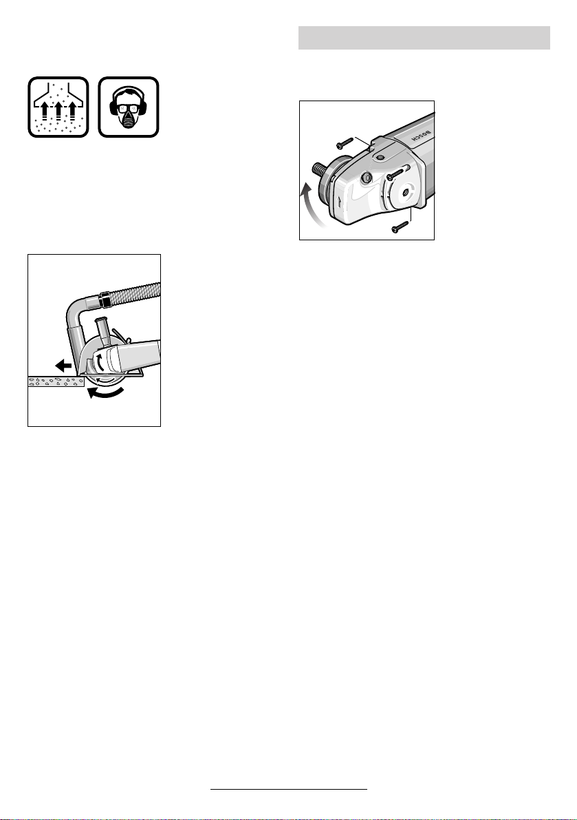
Tronçonnage de pierres
■ L’appareil ne doit être utilisé que pour la
coupe à sec/le ponçage à sec.
Le mieux est d’utili-
ser un disque de
tronçonnage diamanté. Pour empêcher les inclinaisons,
utiliser le chariot de
guidage 26 avec le
capot de protection
spécial à aspiration
de poussières.
N’utiliser l’appareil qu’avec une aspiration de
poussières. Porter aussi un masque de protection anti-poussières.
L’aspirateur doit être
conçu pour l’aspiration des poussières
de pierre.
La société Bosch
vous offre des aspirateurs appropriés.
Mettre l’appareil en
fonctionnement et le
positionner avec la
partie avant du chariot de guidage sur la
pièce à travailler.
Travailler en appliquant une vitesse d’avance
modérée adaptée au matériau (voir figure).
Lors du tronçonnage de matériaux particulière-
ment durs, par exemple de béton ayant une teneur élevée en cailloux, le disque de tronçonnage diamanté risque de chauffer et de subir
ainsi des dommages. Une couronne d’étincelles
autour du disque de tronçonnage diamanté en
est le signe.
Dans ce cas-là, interrompre le processus de tronçonnage et laisser tourner pendant quelque
temps le disque à tronçonnage diamanté sans
sollicitation et en marche à vide afin de le laisser
refroidir.
Un ralentissement perceptible du rythme de travail et une couronne d’étincelles circonférentielle
constituent des indices d’émoussage du disque
de tronçonnage diamanté. Il peut être aiguisé de
nouveau en coupant dans un matériau abrasif
(p. ex. brique de sable calcaire).
Rotation de la tête de l’appareil
■ Avant toute intervention sur l’appareil, tou-
jours retirer la fiche du câble d’alimenta-
tion de la prise de courant.
Il est possible de
tourner la tête de
l’appareil par étapes
de 90° par rapport
au carter de l’appa-
reil. Ceci permet de
mettre l’interrupteur
Marche/Arrêt dans
une position de maniement favorable à
des utilisations spé-
cifiques; p. ex. pour
des travaux de tronçonnage avec chariot de
guidage 26 (accessoire, non vendu en France)/
support de tronçonnage 29 (accessoire) ou pour
les gauchers.
Dévisser complètement les quatre vis.
Tourner la tête de l’appareil avec précaution et
sans la détacher du carter dans sa nouvelle position.
Remettre les vis en place et bien les serrer.
31 • 1 609 929 F55 • TMS • 18.12.03
Français - 8
Page 31

Changement de position de la
poignée de l’appareil
(GWS 24/26-180/230 (J)BV)
➋
28
27
➊
La poignée de l’appareil 28 peut être tournée
de 90° vers la gauche et vers la droite par rapport
au carter moteur. Ceci permet de mettre l’inter-
rupteur Marche/Arrêt dans une position de maniement favorable à des utilisations spécifiques;
p. ex. pour des travaux de tronçonnage avec
chariot de guidage/support de tronçonnage (accessoire) ou pour les gauchers.
Tirer fortement le déverrouillage de la poignée 27
dans le sens de la flèche (
tourner la poignée 28 dans la position dési-
➋) jusqu’à ce qu’elle s’encliquette. La figure
rée (
ci-dessus montre la poignée 28 tournée de 90°.
Le déverrouillage de la poignée 27 ainsi
☞
que l’interrupteur Marche/Arrêt 3 disposent d’un verrouillage de sécurité.
Il n’est donc pas possible de mettre l’appa-
reil en fonctionnement tant que la poignée 28 n’est pas encliquetée dans l’une
des trois positions possibles.
La poignée 28 ne peut pas être déver-
rouillée tant que l’interrupteur Marche/Arrêt 3 est bloqué.
➊) et en même temps
Nettoyage et entretien
■ Avant toute intervention sur l’appareil, tou-
jours retirer la fiche du câble d’alimenta-
tion de la prise de courant.
Pour obtenir un travail sûr et satisfaisant,
☞
nettoyer régulièrement l’appareil ainsi que
ses ouïes de refroidissement.
Dans certaines conditions d’exploitation
délicates, pendant l’usinage de métaux, de
la poussière conductrice d’électricité peut
se déposer à l’intérieur de l’appareil et ainsi
en altérer l’isolation de protection. Si tel est
le cas, Bosch recommande l’emploi d’un
dispositif d’aspiration stationnaire, de souffler fréquemment dans les ouïes de refroidissement et de monter en amont un disjoncteur différentiel.
Quand les éléments amortissant les vibrations se
trouvant sur le dispositif pour amortissement des
vibrations 4 sont endommagés, par ex. quand ils
sont légèrement déchirés, envoyer l’appareil
dans un service après-vente (pour les adresses,
cf. chapitre « Service après-vente »).
Si, malgré tous les soins apportés à la fabrication
et au contrôle de l’appareil, celui-ci devait avoir
un défaut, la réparation ne doit être confiée qu’à
une station de service après-vente agréée pour
outillage Bosch.
Pour toute demande de renseignements ou commande de pièces de rechange, nous préciser impérativement le numéro de référence à dix chiffres de la appareil indiqué sur la plaque signaléti-
que.
32 • 1 609 929 F55 • TMS • 18.12.03
Français - 9
Page 32

Instructions de protection de
l’environnement
Récupération des matières premières plutôt
qu’élimination des déchets
Les appareils, comme d’ailleurs leurs accessoires et emballages, doivent pouvoir suivre chacune une voie de recyclage appropriée.
Ce manuel d’instructions a été fabriqué à partir
d’un papier recyclé blanchi sans chlore.
Nos pièces plastiques ont été marquées en vue
d’un recyclage sélectif des différents matériaux.
Service Après-Vente
Vous trouverez des vues éclatées ainsi que
des informations concernant les pièces de rechange sous :
www.bosch-pt.com
France
Information par Minitel 11
Nom : Bosch Outillage
Loc : Saint Ouen
Dépt : 93
Robert Bosch France S.A.
Service Après-vente/Outillage
B.P. 67-50, Rue Ardoin
93402 St. Ouen Cedex
✆ Service conseil client .................... 0143 11 9002
Numéro Vert
.................................... 0 800 05 50 51
Déclaration de conformité
Nous déclarons sous notre propre responsabilité
que ce produit est en conformité avec les normes
ou documents normalisés suivants : EN 50 144
conformément aux réglementations 89/336/CEE,
98/37/CE.
Dr. Egbert Schneider Dr. Eckerhard Strötgen
Senior Vice President Head of Product
Engineering Certification
Robert Bosch GmbH, Geschäftsbereich Elektrowerkzeuge
Sous réserve de modifications
Belgique
✆ ..................................................... +32 (0)2 / 525 51 43
..................................................... +32 (0)2 / 525 54 20
Fax
E-Mail : Outillage.Gereedschappen@be.bosch.com
Suisse
✆ .................................................... +41 (0)1 / 8 47 16 16
.................................................... +41 (0)1 / 8 47 16 57
Fax
✆ Service conseil client ................. 0 800 55 11 55
33 • 1 609 929 F55 • TMS • 18.12.03
Français - 10
Page 33

Características técnicas
Amoladora GWS 21-180 HV
PROFESSIONAL
GWS 21-230 HV
PROFESSIONAL
GWS 24-180 BV
PROFESSIONAL
Número de pedido 0 601 851 B.. 0 601 852 B.. 0 601 853 B..
Con limitación de la corriente
de arranque
GWS 21-180 JHV
PROFESSIONAL
GWS 21-230 JHV
PROFESSIONAL
GWS 24-180 JBV
PROFESSIONAL
Número de pedido 0 601 851 G.. 0 601 852 G.. 0 601 853 G..
Potencia absorbida nominal* [W] 2 100 2 100 2 400
Potencia útil [W] 1 350 1 350 1 700
Revoluciones en vacío [min-1] 8 500 6 500 8 500
Ø de discos de amolar, máx. [mm] 180 230 180
Rosca del husillo M 14 M 14 M 14
Peso sin cable de red, aprox. [kg] 4,4 4,4 5,2
Clase de protección / II / II / II
Amoladora GWS 24-230 BV
PROFESSIONAL
GWS 26-180 BV
PROFESSIONAL
GWS 26-230 BV
PROFESSIONAL
Número de pedido 0 601 854 B.. 0 601 855 B.. 0 601 856 B..
Con limitación de la corriente
de arranque
GWS 24-230 JBV
PROFESSIONAL
GWS 26-180 JBV
PROFESSIONAL
GWS 26-230 JBV
PROFESSIONAL
Número de pedido 0 601 854 G.. 0 601 855 G.. 0 601 856 G..
Potencia absorbida nominal* [W] 2 400 2 600 2 600
Potencia útil [W] 1 700 1 800 1 800
Revoluciones en vacío [min-1] 6 500 8 500 6 500
Ø de discos de amolar, máx. [mm] 230 180 230
Rosca del husillo M 14 M 14 M 14
Peso sin cable de red, aprox. [kg] 5,2 5,2 5,2
Clase de protección / II / II / II
Preste atención al nº de pedido de su máquina. Las denominaciones comerciales en ciertas máquinas pueden variar.
Los picos de intensidad durante la conmutación causan un descenso transitorio de la tensión. Si las condiciones en la red
fuesen desfavorables, ello puede llegar a afectar a otros aparatos. Con impedancias de red inferiores a 0,25 ohmios es
muy improbable que se produzcan perturbaciones.
* Indicaciones válidas para tensiones nominales [U] de 230/240 V. Estas indicaciones pueden variar para tensiones
menores y en algunas ejecuciones para ciertos países.
Utilización reglamentaria
El aparato ha sido proyectado para tronzar, desbastar y cepillar metales y materiales de piedra
sin la aportación de agua. Al tronzar piedra es
obligatorio utilizar el soporte guía.
Indicaciones concernientes a la
estática
Las ranuras en paredes portantes deben practicarse conforme a la norma DIN 1053 parte 1, o
bien, de acuerdo a las disposiciones específicas
de cada país.
Es imperativo atenerse a estas disposiciones.
Antes de iniciar el trabajo debe consultarse al
aparejador, arquitecto o los responsables de la
dirección de obras.
34 • 1 609 929 F55 • TMS • 18.12.03
Español - 1
Información sobre ruidos y
vibraciones
Determinación de los valores de medición según
norma EN 50 144.
El nivel de ruido típico del aparato corresponde a:
nivel de presión de sonido 90 dB (A); nivel de potencia de sonido 103 dB (A).
¡Usar protectores auditivos!
El nivel de vibraciones típico en la mano/brazo es
menor de 2,5 m/s
2
(1,7 m/s2).
Page 34

Elementos del aparato
La numeración de los elementos del aparato está
referida a su imagen en la página ilustrada.
Despliegue y mantenga abierta la solapa con la
imagen del aparato mientras lee las instrucciones de manejo.
1 Rosca para empuñadura adicional (3x)
2 Botón de bloqueo de husillo
3 Interruptor de conexión/desconexión
4 Amortiguador de vibraciones
5 Empuñadura adicional
6 Husillo
7 Caperuza protectora
8 Tornillo de ajuste
9 Palanca de fijación
10 Brida de apoyo con junta anular
11 Disco de desbastar/tronzar *
12 Tuerca de fijación
13 Tuerca de fijación rápida *
14 Tornillo de fijación
Para su seguridad
Solamente puede trabajar sin peligro con el aparato si lee ínte-
gramente las instrucciones de
manejo y las indicaciones de seguridad, ateniéndose estricta-
mente a las recomendaciones
allí comprendidas. Adicionalmente deberán
respetarse las instrucciones de seguridad generales comprendidas en el folleto adjunto.
Déjese instruir prácticamente en el manejo
antes de la primera aplicación.
■ Llevar gafas de protección y protectores audi-
tivos.
■ Para su seguridad, emplee además otros ele-
mentos de protección como guantes de protección, calzado fuerte, casco y mandil.
■ El polvo producido al trabajar puede ser no-
civo para la salud, combustible o explosivo.
Ello requiere tomar unas medidas de protección adecuadas.
Por ejemplo: Ciertos tipos de polvo son cancerígenos. Emplear un equipo de aspiración
para polvo y virutas adecuado, y colocarse
una mascarilla antipolvo.
15 Resalte codificador
16 Caperuza protectora del vaso de esmerilar *
17 Vaso de esmerilar*
18 Llave de dos pivotes para tuerca de fijación*
19 Protección para las manos *
20 Arandelas distanciadoras *
21 Plato lijador de goma*
22 Hoja lijadora*
23 Tuerca tensora*
24 Cepillo de vaso*
25 Disco tronzador diamantado *
26 Soporte guía con caperuza protectora de
aspiración*
27 Desenclavamiento de la empuñadura
28 Empuñadura
29 Mesa de tronzar*
* Los accesorios descritos e ilustrados no correspon-
den en parte al material que se adjunta de serie.
■ El polvo de aleaciones ligeras puede inflamarse o explotar. Mantener siempre limpio el
puesto de trabajo, puesto que al mezclarse el
polvo de diferentes materiales, éstos pueden
resultar especialmente peligrosos.
■ Si llega a dañarse o cortarse el cable de red
durante el trabajo, no tocar el cable, sino extraer inmediatamente el enchufe de la red. No
usar jamás el aparato con un cable deteriorado.
■ Conectar los aparatos utilizados en la intemperie a través de un fusible diferencial con una
corriente de disparo máxima de 30 mA. No exponer el aparato a la lluvia o humedad.
■ Trabajar siempre con el aparato sujetándolo
firmemente con ambas manos y manteniendo
una posición estable.
■ Asegure la pieza de trabajo. Una pieza de
trabajo fijada con unos dispositivos de sujeción, o en un tornillo de banco, se mantiene
sujeta de forma mucho más segura que con la
mano.
■ Mantener el cable siempre detrás del aparato.
■ Siempre desconectar y esperar a que se de-
tenga el aparato, antes de depositarlo.
35 • 1 609 929 F55 • TMS • 18.12.03
Español - 2
Page 35

■ En caso de un corte del fluido eléctrico, o al ex-
traer directamente el enchufe de red, desenclavar inmediatamente el interruptor de
conexión/desconexión y llevarlo a la posición
de desconexión. De esta manera se evita un
arranque accidental.
■ El aparato debe utilizarse solamente para el
tronzado y amolado en seco.
■ Trabajar siempre con la empuñadura adicional
montada en el aparato.
■ Únicamente sujetar la herramienta eléc-
trica por las empuñaduras aisladas en
caso de que el útil pudiera llegar a dañar un
conductor oculto o el propio cable de red
del aparato.
El contacto con un conductor portador de tensión pone bajo tensión las partes metálicas del
aparato pudiendo causar una descarga al
usuario.
■ Utilice unos instrumentos de exploración
adecuados para detectar tuberías y cables
ocultos, o consulte a su compañía abastecedora local.
El contacto con cables eléctricos puede provocar un incendio o sacudida eléctrica. El deterioro de tuberías de gas puede producir una
explosión. La perforación de una tubería de
agua puede causar daños materiales o una
sacudida eléctrica.
■ Al trabajar con discos de desbastar o tronzar
debe emplearse la caperuza protectora 7. Al
trabajar con el plato lijador de goma 21, con el
cepillo de vaso 24, un cepillo de disco, o un
disco lijador segmentado, deberá montarse la
protección para las manos 19 (accesorio especial).
■ Al trabajar piedra emplear un sistema para aspiración de polvo. El aspirador debe estar homologado para aspirar polvo de piedra. Al
tronzar piedra debe utilizarse un soporte guía.
■ No deben trabajarse materiales que contengan amianto.
■ Emplear solamente útiles cuyas revoluciones
admisibles sean como mínimo iguales a las revoluciones en vacío del aparato.
■ Comprobar los útiles antes de su uso. El útil de
amolar debe estar perfectamente montado y
debe girar sin rozar en ningún lado. Efectuar
un funcionamiento de prueba dejándolo girar
en vacío durante 30 segundos como mínimo.
No utilizar los útiles de amolar si están daña-
dos, si giran de forma descentrada o vibran.
■ Proteger el útil de amolar de los golpes, cho-
ques y de la grasa.
■ Aproximar el aparato a la pieza solamente estando conectado.
■ Mantenga alejadas sus manos de los útiles de
amolar en funcionamiento.
■ Observar el sentido de giro. Sujetar siempre el
aparato de manera que las chispas y las partí-
culas producidas al trabajar sean lanzadas en
dirección contraria al cuerpo.
■ Al lijar metales se proyectan chispas. Prestar
atención a que no sean lanzadas contra personas. Por el peligro de incendio existente no
deben encontrarse materiales inflamables en
las proximidades (área de alcance de las chispas).
■ Tenga precaución al practicar ranuras, p. ej.
en paredes portantes: véase “Indicaciones
concernientes a la estática”.
■ Si el disco tronzador llegase a bloquearse repentinamente se obtiene un par de reacción
brusco en el aparato. En estos casos debe
desconectarse inmediatamente el aparato.
■ Observar las dimensiones de los discos de
amolar. El orificio debe ajustar sin holgura en
la brida de apoyo 10. No utilizar piezas de reducción o adaptadores.
■ Jamás deben emplearse los discos tronzado-
res para desbastar. No ejercer una fuerza lateral sobre los discos tronzadores.
■ Atenerse a las instrucciones del fabricante al
montar y aplicar el útil.
■ ¡Atención! El útil continúa funcionando por
inercia después de desconectar el aparato.
■ No sujetar el aparato en un tornillo de banco.
■ Jamás permita que los niños utilicen el apa-
rato.
■ Bosch solamente puede garantizar el funcionamiento correcto del aparato si se utilizan los
accesorios originales previstos.
Montaje de los
dispositivos protectores
■ Antes de cualquier manipulación en el apa-
rato extraer el enchufe de la red.
■ Al trabajar con discos de desbastar o tronzar debe emplearse la caperuza protectora 7.
Caperuza protectora con
tornillo de fijación
El resalte codificador 15 que lleva la caperuza
protectora 7 garantiza que sea montada solamente la caperuza protectora adecuada al tipo
de aparato.
Aflojar el tornillo de fijación 14 si fuese preciso.
36 • 1 609 929 F55 • TMS • 18.12.03
Español - 3
Page 36

Insertar el resalte codificador 15 de la caperuza
protectora 7 en la ranura de codificación del cuello del husillo del cabezal del aparato y girarla a
la posición requerida (posición de trabajo).
El lado cerrado de la caperuza protectora 7
debe mostrar siempre hacia el usuario.
Apretar el tornillo de fijación 14.
Caperuza protectora de cierre rápido
La caperuza protectora viene preajustada al
☞
diámetro del cuello del husillo. Si fuese preciso, puede modificarse la fuerza de apriete
del cierre, aflojando o apretando el tornillo
de ajuste 8. Al realizar esto, deberá cuidarse que la caperuza protectora 7 quede
firmemente sujeta al cuello del husillo.
Aflojar la palanca de fijación 9.
Insertar la caperuza protectora 7 sobre el cuello
del husillo del cabezal del aparato y girarla a la
posición de trabajo requerida.
Para sujetar la caperuza protectora 7 apretar la
palanca de fijación 9.
El lado cerrado de la caperuza protectora 7
debe mostrar siempre hacia el usuario.
Empuñadura adicional
■ Trabajar siempre con la empuñadura adi-
cional montada en el aparato.
Enroscar la empuñadura adicional 5 al cabezal
del aparato de acuerdo al trabajo a realizar.
Amortiguador de vibraciones
El amortiguador integrado 4 y la empuñadura
adicional especial reductora de vibraciones, reducen las vibraciones resultantes a menos de
2
2,5 m/s
jar de manera más cómoda y segura.
, según EN 50 144, lo que permite traba-
No modificar el amortiguador de vibraciones 4 ni la empuñadura adicional. No
seguir utilizando las piezas que estén
dañadas.
Protección para las manos
Al trabajar con el plato lijador de goma 21, con el
cepillo de vaso 24, un cepillo de disco, o un disco
lijador segmentado, deberá montarse la protección para las manos 19 (accesorio especial). La
protección para las manos 19 se sujeta junto con
la empuñadura adicional 5.
Montaje de los útiles
■ Antes de cualquier manipulación en el apa-
rato extraer el enchufe de la red.
Emplear solamente útiles cuyas revoluciones admisibles sean como mínimo
iguales a las revoluciones en vacío del
aparato.
Los discos de desbastar y de tronzar
pueden alcanzar temperaturas muy elevadas al trabajar; espere hasta que se
enfríen antes de tocarlos.
■ Limpiar el husillo y todas las partes a montar.
Para apretar y aflojar los útiles retener el husillo 6 presionando el botón de bloqueo del husillo 2.
¡Accionar el botón de bloqueo del husillo 2
solamente con el husillo detenido!
Discos de desbastar/tronzar
Observar las dimensiones de los discos de amolar. El orificio debe ajustar sin holgura en la brida
de apoyo 10. No utilizar piezas de reducción o
adaptadores.
Al montar discos tronzadores diamantados debe
prestarse atención a que la flecha de sentido de
giro del disco tronzador diamantado coincida con
el sentido de giro del aparato (flecha de sentido
de giro sobre el cabezal del aparato).
Realizar el montaje según la hoja ilustrada.
Enroscar la tuerca de fijación 12 y apretarla con
la llave de dos pivotes (ver apartado “Tuerca de
fijación rápida”).
El cuello de centrado
de la brida de
apoyo 10 lleva una
junta anular (pieza
10
Si la junta anular faltase o estuviese dañada,
es imprescindible montar una junta nueva (nº de
pedido 1 600 210 039) antes de emplear la brida
de apoyo 10.
Después de montar el útil de amolar,
☞
debe verificarse si éste está correctamente montado y si gira sin rozar, antes
de conectar el aparato.
de plástico).
37 • 1 609 929 F55 • TMS • 18.12.03
Español - 4
Page 37

Disco lijador segmentado
(plato pulidor de fibra)
Para ciertas aplicaciones deberá desmontarse la
caperuza protectora 7 y montar la protección
para las manos 19. Montar la brida de apoyo especial 10 (accesorio especial, nº de pedido
2 605 703 028) y el disco lijador segmentado sobre el husillo portamuelas 6. Enroscar la tuerca
de fijación 12 y apretarla con la llave de dos pivotes.
Plato lijador de goma 21
Para ciertas aplicaciones deberá desmontarse la
caperuza protectora 7 y montar la protección
para las manos 19.
Antes de montar el plato lijador de goma 21 montar las 2 arandelas distanciadoras 20 en el husillo
portamuelas.
Realizar el montaje según la hoja ilustrada.
Enroscar la tuerca tensora 23 y apretarla con la
llave de dos pivotes.
Cepillo de vaso 24/cepillo de disco
Para ciertas aplicaciones deberá desmontarse la
caperuza protectora 7 y montar la protección
para las manos 19.
El útil tiene que poder enroscarse a una profundidad suficiente en el husillo 6 para que asiente
firmemente contra la brida del husillo que se encuentra al final de la rosca del husillo. Apretar el
útil con la llave fija.
Vaso de esmerilar
Al trabajar con vasos de esmerilar emplear una caperuza protectora especial 16.
El vaso de esmerilar 17 debe sobresalir de la caperuza protectora 16 lo imprescindible nada más
para realizar el trabajo.
Reajustar la caperuza protectora 16 a esta medida.
Realizar el montaje según la hoja ilustrada.
Enroscar la tuerca de fijación 12 y apretarla con
la llave de dos pivotes acodada 18 prevista.
Tuerca de fijación rápida
En lugar de la tuerca de fijación 12 puede emplearse la tuerca de fijación rápida 13 (accesorio
especial). Los útiles de amolar pueden montarse
entonces sin precisar un útil adicional.
La tuerca de fijación rápida 13 debe emplearse solamente en discos de desbastar/tronzar.
Utilizar únicamente una tuerca de fijación rápida 13 en perfecto estado.
Al montar la tuerca, prestar atención a que la
cara que lleva la inscripción no asiente sobre
el disco de amolar; la flecha debe encontrarse además sobre la marca índice 30.
Retener el husillo
30
13
portamuelas presionando el botón de
bloqueo del husillo 2.
Apretar la tuerca de
fijación rápida girando con fuerza el
disco de amolar en el
sentido de las agujas
del reloj.
2
Una tuerca de fijación rápida sin dañar,
correctamente montada, se deja aflojar a
mano girando el anillo moleteado en sentido contrario a las
agujas del reloj.
No intentar aflojar
nunca con una te-
2
naza una tuerca de
fijación rápida bloqueada, sino con la
llave de dos pivotes. Aplicar la llave
de dos pivotes según
se muestra en la figura.
38 • 1 609 929 F55 • TMS • 18.12.03
Español - 5
Page 38

Útiles admisibles
Pueden emplearse todos los útiles mencionados
en estas instrucciones de manejo.
Las revoluciones [min
rica [m/s] admisibles en los útiles deben corresponder, como mínimo, a los valores indicados en
la tabla.
Deben considerarse por lo tanto siempre las re-
voluciones/velocidad periférica admisibles
marcadas sobre la etiqueta de los útiles.
Db d[min
d
180
D
b
D
b
23088
180
230––––
d
100 30 M 14 8 500 45
D
-1
] o velocidad perifé-
máx.
[mm] [mm]
22,2
22,2
-1
] [m/s]
8 500
6 5008080
8 500
6 5008080
Puesta en servicio
Cerciorarse de que la tensión de la red sea
correcta: La tensión de la fuente de energía
debe coincidir con las indicaciones en la placa de
características del aparato. Los aparatos marcados con 230 V pueden funcionar también a
220 V.
Conexión y desconexión
Para poner en marcha el aparato desplazar hacia adelante el interruptor de conexión/desco-
nexión 3 y presionarlo a continuación.
Para enclavar el interruptor de conexión/desconexión 3 continuar desplazándolo hacia adelante, manteniéndolo presionado.
Para desconectar el aparato soltar, o presionar
y soltar si estuviese enclavado, el interruptor de
conexión/desconexión 3.
Interruptor de ejecución sin enclavamiento
(requerido en ciertos países):
Para poner en marcha el aparato desplazar hacia adelante el interruptor de conexión/desco-
nexión 3 y presionarlo a continuación.
Para desconectar el aparato soltar el interruptor
de conexión/desconexión 3.
¡Funcionamiento de prueba!
☞
Comprobar los útiles antes de su uso. El
útil debe estar perfectamente montado y
debe girar sin rozar en ningún lado. Efectuar un funcionamiento de prueba deján-
dolo girar en vacío durante 30 segundos
como mínimo. No utilizar los útiles si están
dañados, si giran de forma descentrada o
vibran.
Limitación de la corriente de
arranque (Tipo J)
Gracias al arranque suave del aparato es
suficiente un fusible de 16 A.
Los aparatos sin limitación de la corriente
de arranque necesitan un fusible de mayor
amperaje (utilizar por lo menos un fusible
lento de 16 A).
Instrucciones de trabajo
■ Sujetar la pieza de trabajo, a no ser que
quede bien firme por su propio peso.
■ No solicitar el aparato de manera que llegue a detenerse.
■ Los discos de desbastar y de tronzar pueden alcanzar temperaturas muy elevadas al
trabajar; espere hasta que se enfríen antes
de tocarlos.
Desbastado
Con ángulos de ataque de 30° a
40° se obtiene el mejor resultado al
desbastar. Guiar el aparato con
movimiento de vaivén ejerciendo
una presión moderada. Así, no se
produce un calentamiento excesivo
y se evita que la pieza de trabajo
cambie de color y que se marque
con estrías.
Jamás deben usarse discos tronzadores para desbastar.
Disco lijador segmentado
(plato pulidor de fibra)
Con el disco lijador segmentado (accesorio especial) pueden trabajarse también superficies
abombadas y perfiles (amolado de contornos).
Los discos lijadores segmentados tienen una duración notablemente mayor que las hojas lijadoras, generan un nivel de ruido menor, y calientan
menos la pieza al trabajar.
39 • 1 609 929 F55 • TMS • 18.12.03
Español - 6
Page 39

Tronzado
Al tronzar, el disco no debe presionarse excesivamente ni ladearse,
ni guiarse con un movimiento oscilante. Trabajar con un avance moderado y adecuado al tipo de material a trabajar.
No frene los discos tronzadores en
marcha por inercia presionándolos
lateralmente contra el material.
Al tronzar es importante que el sentido
de avance de la má-
quina sea el correcto.
El aparato debe
guiarse siempre a
contramarcha,
¡nunca en sentido
opuesto! De lo contrario existe el riesgo
de que el aparato sea
rechazado bruscamente.
Mesa de tronzar
Con la mesa de tronzar 29 (accesorio especial)
pueden tronzarse piezas de trabajo de igual longitud con un ángulo de inclinación de 0 a 45°.
Atenerse estrictamente a las instrucciones de seguridad y trabajo indicadas en las respectivas
instrucciones de manejo de la mesa de tronzar.
Solamente emplear mesas de tronzar originales
Bosch.
Tronzado de piedra
■ El aparato debe utilizarse solamente para
el tronzado y amolado en seco.
Se recomienda utilizar un disco tronzador diamantado.
Para evitar que el
aparato se ladee,
emplear el soporte
guía 26 con una caperuza protectora de
aspiración especial.
Solamente utilizar el aparato con un equipo de
aspiración de polvo. Colocarse adicionalmente
una mascarilla antipolvo.
El aspirador debe estar homologado para
succionar polvo de
piedra.
Bosch le ofrece el aspirador adecuado.
Conectar el aparato y
asentar la parte delantera del soporte
guía sobre la pieza
de trabajo.
Guiar el aparato con un avance moderado y adecuado al tipo de material a trabajar (figura).
Al tronzar materiales muy duros, p. ej. hormigón
con un alto contenido de áridos, puede llegar a
sobrecalentarse el disco tronzador diamantado
llegando incluso a dañarse. Esto se manifiesta
por una corona de chispas en el perímetro del
disco tronzador diamantado.
En estos casos debe interrumpirse el proceso de
tronzado para enfriar el disco tronzador diamantado dejándolo funcionar brevemente sin carga a
las revoluciones en vacío.
Tanto una disminución considerable en la progresión del trabajo como una corona de chispas
en el perímetro del disco tronzador diamantado
son síntomas de que el disco está mellado. Éste
puede reafilarse efectuando unos cortes en material abrasivo (p. ej. en arenisca calcárea).
40 • 1 609 929 F55 • TMS • 18.12.03
29
Español - 7
Page 40

Giro del cabezal del aparato
■ Antes de cualquier manipulación en el apa-
rato extraer el enchufe de la red.
El cabezal del aparato puede montarse
girado en pasos de
90° respecto a la carcasa del aparato.
Ello permite situar al
interruptor de conexión/desconexión
en una posición más
cómoda al efectuar
trabajos especiales
raciones de tronzado con un soporte guía 26/
mesa de tronzar 29 (accesorios especiales), o en
caso de que el usuario sea zurdo.
Desenroscar completamente los cuatro tornillos.
Girar el cabezal del aparato con cuidado, y sin
separarlo de la carcasa, hasta la nueva posición.
Enroscar nuevamente los tornillos, y apretarlos.
como, p. ej., en ope-
Giro de la empuñadura
(GWS 24/26-180/230 (J)BV)
➋
28
27
➊
La empuñadura 28 deja girarse 90° hacia la izquierda y derecha respecto a la carcasa motor.
Ello permite posicionar el interruptor de conexión/desconexión en una posición de manejo
más favorable en ciertos casos; p. ej. si el usuario fuese zurdo, o al realizar operaciones de tronzado con un soporte guía/mesa de tronzar (accesorio especial).
Tirar firmemente del desenclavamiento de la empuñadura 27 en dirección de la flecha (
rando simultáneamente (
la posición deseada, hasta enclavarla. La figura
muestra la empuñadura 28 girada en 90°.
➋) la empuñadura 28 a
➊) gi-
El mecanismo de desenclavamiento de la
☞
empuñadura 27 y el interruptor de conexión/desconexión 3 disponen de un mecanismo de seguridad.
El aparato no deja conectarse mientras
que la empuñadura 28 no se encuentre enclavada en una de las tres posiciones posibles.
La empuñadura 28 no deja girarse si se
encuentra enclavado el interruptor de conexión/desconexión 3.
Mantenimiento y limpieza
■ Antes de cualquier manipulación en el apa-
rato extraer el enchufe de la red.
Mantener siempre limpios el aparato y las
☞
rejillas de refrigeración para poder trabajar
con seguridad.
En casos especiales puede ocurrir que se
acumule polvo metálico susceptible de
conducir electricidad en el interior del aparato. Ello puede llegar a mermar la protección de aislamiento del aparato. En estos
casos se recomienda la aplicación de un
equipo de aspiración estacionario, soplar
frecuentemente las rejillas de refrigeración, e intercalar un fusible diferencial.
Si los elementos del amortiguador de vibraciones 4 estuviesen deteriorados, p. ej. fisurados,
deberá enviarse el aparato para su reparación a
un servicio técnico (ver direcciones bajo el pá-
rrafo “Servicio técnico y asistencia al cliente”).
Si a pesar de los esmerados procesos de fabricación y control, el aparato llegase a averiarse, la
reparación deberá encargarse a un taller de servicio autorizado para herramientas eléctricas
Bosch.
Al realizar consultas o solicitar piezas de repuesto, es imprescindible indicar siempre el nú-
mero de pedido de 10 dígitos que figura en la
placa de características del aparato.
41 • 1 609 929 F55 • TMS • 18.12.03
Español - 8
Page 41

Protección del medio ambiente
México
Robert Bosch S.A. de C.V.
✆ Interior:............................ +52 (0)1 / 800 627 1286
✆ D.F.:...................................... +52 (0)1 / 52 84 30 62
E-Mail: arturo.fernandez@mx.bosch.com
Recuperación de materias primas en lugar de
producir desperdicios
El aparato, los accesorios y el embalaje debieran
someterse a un proceso de recuperación que
respete el medio ambiente.
Estas instrucciones se han impreso sobre papel
reciclado sin la utilización de cloro.
Para efectuar un reciclaje selectivo se han identificado las piezas de plástico.
Servicio técnico y asistencia al
cliente
Los dibujos de despiece e informaciones sobre las piezas de repuesto las encontrará en
internet bajo:
www.bosch-pt.com
España
Robert Bosch España, S.A.
Departamento de ventas
Herramientas Eléctricas
C/Hermanos García Noblejas, 19
28037 Madrid
✆ Asesoramiento al cliente.... +34 901 11 66 97
........................................................... +34 91 327 98 63
Fax
Venezuela
Robert Bosch S.A.
Final Calle Vargas. Edf. Centro Berimer P.B.
Boleita Norte
Caracas 107
✆ ..................................................... +58 (0)2 / 207 45 11
Argentina
Robert Bosch Argentina S.A.
Córdoba 5160
1414 Buenos Aires (Capital Federal)
Atención al Cliente
✆ ................................................. +54 (0)810 / 555 2020
E-Mail: herramientas.bosch@ar.bosch.com
Perú
Autorex Peruana S.A.
República de Panamá 4045,
Lima 34
✆ ...................................................... +51 (0)1 / 475-5453
E-Mail: vhe@autorex.com.pe
Chile
EMASA S.A.
Irarrázaval 259 – Ñuñoa
Santiago
✆ ....................................................... +56 (0)2 / 520 3100
E-Mail: emasa@emasa.cl
Declaración de conformidad
Declaramos bajo nuestra sola responsabilidad
que este producto está en conformidad con las
normas o documentos normalizados siguientes:
EN 50 144 de acuerdo con las regulaciones
89/336/CEE, 98/37/CE.
Dr. Egbert Schneider Dr. Eckerhard Strötgen
Senior Vice President Head of Product
Engineering Certification
42 • 1 609 929 F55 • TMS • 18.12.03
Robert Bosch GmbH, Geschäftsbereich Elektrowerkzeuge
Reservado el derecho de modificaciones
Español - 9
Page 42

Dados técnicos do aparelho
Rebarbadora GWS 21-180 HV
PROFESSIONAL
GWS 21-230 HV
PROFESSIONAL
GWS 24-180 BV
PROFESSIONAL
Nº de encomenda 0 601 851 B.. 0 601 852 B.. 0 601 853 B..
Com limitação de corrente de
arranque
GWS 21-180 JHV
PROFESSIONAL
GWS 21-230 JHV
PROFESSIONAL
GWS 24-180 JBV
PROFESSIONAL
Nº de encomenda 0 601 851 G.. 0 601 852 G.. 0 601 853 G..
Potência nominal consumida* [W] 2 100 2 100 2 400
Potência útil [W] 1 350 1 350 1 700
Rotações em vazio [min-1] 8 500 6 500 8 500
Discos abrasivos-Ø, máx. [mm] 180 230 180
Rosca de veio de rectificação M 14 M 14 M 14
Peso sem cabo de rede, aprox. [kg] 4,4 4,4 5,2
Classe de protecção / II / II / II
Rebarbadora GWS 24-230 BV
PROFESSIONAL
GWS 26-180 BV
PROFESSIONAL
GWS 26-230 BV
PROFESSIONAL
Nº de encomenda 0 601 854 B.. 0 601 855 B.. 0 601 856 B..
Com limitação de corrente de
arranque
GWS 24-230 JBV
PROFESSIONAL
GWS 26-180 JBV
PROFESSIONAL
GWS 26-230 JBV
PROFESSIONAL
Nº de encomenda 0 601 854 G.. 0 601 855 G.. 0 601 856 G..
Potência nominal consumida* [W] 2 400 2 600 2 600
Potência útil [W] 1 700 1 800 1 800
Rotações em vazio [min-1] 6 500 8 500 6 500
Discos abrasivos-Ø, máx. [mm] 230 180 230
Rosca de veio de rectificação M 14 M 14 M 14
Peso sem cabo de rede, aprox. [kg] 5,2 5,2 5,2
Classe de protecção / II / II / II
Por favor observar o número de encomenda da sua máquina. A designação comercial de diversas máquinas pode variar.
Os processos de ligação causam durante pouco tempo reduções de tensão. No caso de condições de rede desfavoráveis,
podem ocorrer impedimentos devido a outros aparelhos. No caso de impendâncias de rede inferiores a 0,25 ohms não é
de se esperar quaisquer interferências.
* As indicações valem para tensões nominais de [U] 230/240 V. Estas indicações podem variar no caso de tensões mais
baixas e modelos específicos de países.
Utilização de acordo com as
disposições
O aparelho é determinado para cortar, desbastar
e escovar materiais de metal e de pedra, sem utilizar água. Para cortar pedras é necessário utilizar um carril de guia.
Indicações sobre a estática
Aberturas em paredes portantes devem ser realizadas de acordo com a norma DIN 1053 parte 1
ou com as disposições do respectivo país.
É imprescindível seguir estas directivas. Antes
de iniciar o trabalho, deverá consultar o especialista em estática, o arquitecto ou os responsáveis
pela obra.
43 • 1 609 929 F55 • TMS • 18.12.03
Português - 1
Informações sobre ruído e
vibrações
Valores de medida de acordo com EN 50 144.
O nível de ruído avaliado A do aparelho é
tipicamente: Nível de pressão acústica
90 dB (A). Nível de potência acústica 103 dB (A).
Utilize protectores auriculares!
A vibração do braço e da mão é tipicamente inferior a 2,5 m/s
2
(1,7 m/s2).
Page 43

Elementos do aparelho
A numeração dos elementos do aparelho referese à apresentação do aparelho na página de gráficos.
Por favor abra a aba com a apresentação do
aparelho, e deixe a página aberta enquanto ler a
instrução de serviço.
1 Rosca do punho adicional (3x)
2 Tecla de travamento de veio
3 Interruptor de ligar/desligar
4 Atenuação de vibrações
5 Punho adicional
6 Veio de rectificação
7 Capa de protecção
8 Parafuso de ajuste
9 Alavanca de aperto
10 Flange de admissão com O-Ring
11 Disco de desbastar/cortar*
12 Porca de aperto
13 Porca de aperto rápido *
Para sua segurança
Um trabalho seguro com o aparelho só é possível após ter lido
completamente as instruções de
serviço e as indicações de segurança e após observar rigorosa-
mente as indicações nelas contidas. Adicionalmente deverá seguir as indicações gerais de segurança que se encontram
no caderno em anexo. Uma instrução prática
é vantajosa.
■ Usar óculos de protecção e protecção para os
ouvidos.
■ Para a sua segurança, use também outros
utensílios de segurança pessoal, como por
exemplo luvas de protecção, sapatos firmes e
robustos, capacete e avental.
■ Durante o trabalho são produzidos pós que
podem ser nocivos à saúde, inflamáveis ou
explosivos. São necessárias medidas de protecção adequadas.
Por exemplo: Alguns pós são considerados
cancerígenos. Utilize uma apropriada aspiração de pó/aparas e use uma máscara de protecção contra pó.
14 Parafuso de aperto
15 Ressalto de codificação
16 Capa de protecção para mós tipo tacho *
17 Mós tipo tacho*
18 Chave de dois furos para porca de aperto*
19 Protecção para as mãos *
20 Discos distanciadores *
21 Prato de lixar de borracha *
22 Lixa*
23 Porca redonda*
24 Escova tipo tacho*
25 Disco de diamante para cortar *
26 Carril de guia com capa de aspiração*
27 Destravamento do punho
28 Punho
29 Suporte de corte*
* Os acessórios ilustrados e descritos nas instruções
de serviço nem sempre são abrangidos pelo conjunto
de fornecimento!
■ Pó de metal leve pode queimar ou explodir.
Sempre manter o local de trabalho limpo, pois
misturas de material são extremamente perigosas.
■ Caso o cabo de rede for danificado ou cortado
durante o trabalho, não toque no cabo. Tire
imediatamente a ficha da tomada. Jamais utilizar o aparelho com um cabo danificado.
■ Aparelhos utilizados ao ar livre devem ser conectados através de um interruptor de protecção contra corrente residual com uma corrente
de activação de no máximo 30 mA. Não utilizar o aparelho na chuve ou em ambientes hú-
midos.
■ Ao trabalhar com o aparelho, segure-o sempre
com ambas as mãos e mantenha uma posição
firme.
■ Fixar a peça a ser trabalhada. Uma peça a
ser trabalhada fixa através de dispositivos de
fixação ou torno de bancada está mais fixo do
que quando segurado com a mão.
■ Conduzir o cabo sempre por detrás da má-
quina.
44 • 1 609 929 F55 • TMS • 18.12.03
Português - 2
Page 44

■ Sempre desligar o aparelho antes de depositá-la e aguardar até que o aparelho páre
completamente.
■ No caso de falha de corrente ou se fôr puxada
a tomada de corrente, deverá destravar imediatamente o interruptor de ligar/desligar e colocar na posição desligada. Isto evita um novo
arranque involuntário.
■ O aparelho só deve ser utilizado para cortes a
seco/polimento a seco.
■ O punho adicional deve ser montado durante
todos os trabalhos com o aparelho.
■ Apenas segurar a ferramenta eléctrica pe-
las superfícies de manuseio isoladas, caso
a ferramenta de utilização possa entrar em
contacto com uma tubulação escondida no
muramento ou o próprio cabo eléctrico.
O contacto com um cabo que conduz tensão
eléctrica, colocará sob tensão as partes de
metal expostas da ferramenta e pode levar a
um choque eléctrico.
■ Utilize aparelhos detectores apropriados
para detectar cabos de alimentação ou
peça apoio da sua firma de abastecimento.
O contacto com cabos eléctricos pode provocar incêndio e choque eléctrico. O dano de
uma linha de gás pode levar a uma explosão.
Uma perfuração de um tubo de água provoca
um dano material ou pode provocar um choque eléctrico.
■ Para trabalhos com discos de desbastar ou de
cortar, é necessário que a capa de protecção 7 esteja montada. Para trabalhos com o
prato de lixar de borracha 21 ou com a escova
em forma de tacho 24/escova em forma de
disco/disco abrasivo em forma de leque, é necessário montar a protecção para as mãos 19
(acessório).
■ Use uma aspiração a vácuo para pó de pedras
ao trabalhar com as tais. O aspirador de pó
deve ser aprovado para aspirar pó de pedras.
Usar um carril de guia para cortar pedras.
■ Materiais que contém amianto não devem ser
trabalhados.
■ Apenas utilize ferramentas abrasivas, com um
número de rotações admissível que seja no
mínimo tão alto como o número de rotações
em vazio do aparelho.
■ Controlar as ferramentas abrasivas antes da
utilização. A ferramenta abrasiva deve estar
perfeitamente montada e deve poder girar livremente. Realizar um funcionamento de ensaio sem carga, durante no mínimo 30 segundos. Ferramentas abrasivas danificadas, descentradas ou vibrantes não devem ser
utilizadas.
■ Proteger as ferramentas abrasivas contra golpes, trepidações e gordura.
■ Só contactar a peça a ser trabalhada quando
o aparelho já estiver ligado.
■ Não toque nas ferramentas abrasivas em rota-
ção.
■ Observar o sentido de rotação. Sempre segu-
rar o aparelho de forma que faíscas ou pó de
lixar voem para longe do corpo.
■ Ao lixar metais voam faíscas. Observe que ne-
nhuma pessoa corra perigo. Devido ao perigo
de incêndio, não devem encontra-se materiais
inflamáveis nas proximidades (área de vôo de
faíscas).
■ Cuidado ao abrir cavidades p. ex. em paredes
portantes: Veja as indicações sobre a estática.
■ O aparelho reage com movimentos bruscos,
quando o disco de corte é bloqueado. Neste
caso o aparelho deve ser desligado imediatamente.
■ Observar as dimensões dos discos abrasivos.
O diâmetro do furo deve ajustar-se sem folga
à flange de admissão 10. Não utilizar peças de
redução ou adaptadores.
■ Jamais utilize discos de corte para desbastar.
Não pressionar lateralmente os discos de
corte.
■ Observe as indicações do fabricante sobre a
montagem e a aplicação da ferramenta abrasiva.
■ Cuidado! A lixa funciona por inércia após des-
ligar o aparelho.
■ Não fixar o aparelho com um torno de ban-
cada.
■ Jamais deverá permitir que crianças utilizem
este aparelho.
■ A Bosch só pode assegurar um funciona-
mento perfeito do aparelho, se para este aparelho foram utilizados acessórios originais previstos para tal.
45 • 1 609 929 F55 • TMS • 18.12.03
Português - 3
Page 45

Montar os dispositivos
de protecção
■ Tirar a ficha da tomada antes do todos os
trabalhos no aparelho.
■ Para trabalhos com discos de desbastar ou
de cortar, é necessário que a capa de protecção 7 esteja montada.
Capa de protecção com parafuso de
aperto
O ressalto de codificação 15 na capa de protec-
ção 7 assegura, que apenas uma capa de pro-
tecção corresponda à um respectivo tipo de aparelho.
Se necessário, deverá soltar o parafuso de
aperto 14.
Colocar a capa de protecção 7 com o ressalto de
codificação 15 na ranhura de codificação que se
encontra na gola do veio do cabeçote do aparelho e girar até a posição necessária (posição de
trabalho).
O lado fechado da capa de protecção 7 deve
mostrar sempre para o operador.
Apertar o parafuso de aperto 14.
Capa de protecção com fecho rápido
A capa de protecção é pré-ajustada para o
☞
diâmetro da gola do veio. Se necessário, a
força de aperto do fecho pode ser alterada,
afrouxando ou apertando o parafuso de
ajuste 8. Observar sempre que a capa de
protecção 7 esteja firmemente posicionada sobre a gola do veio.
Abrir a alavanca de aperto 9.
Colocar a capa de protecção 7 sobre a gola do
veio do cabeçote do aparelho e girar para a posição necessária (posição de trabalho).
Para fixar a capa de protecção 7, é necessário
fechar a alavanca de aperto 9.
O lado fechado da capa de protecção 7 deve
mostrar sempre para o operador.
Punho adicional
■ O punho adicional deve ser montado durante todos os trabalhos com o aparelho.
Aparafusar o punho adicional 5 no cabeçote do
aparelho, de acordo com o tipo de trabalho a ser
executado.
Atenuação de vibrações
A atenuação de vibrações 4 e o punho adicional
com atenuação de vibração reduzem vibrações
conforme EN 50 144 até abaixo de 2,5 m/s
possibilitam um trabalho com poucas vibrações e
portanto agradável e seguro.
Não devem ser efectuadas quaisquer
modificações na atenuação de vibrações 4 nem no punho adicional. Partes
danificadas não devem continuar a ser
utilizadas.
2
e
Protecção para as mãos
Para trabalhos com o prato de lixar de borracha 21 ou com a escova em forma de tacho 24/
escova em forma de disco/disco abrasivo em
forma de leque, é necessário montar a protecção
para as mãos 19 (acessório). A protecção para
mãos 19 é fixada com o punho adicional 5.
Montar as ferramentas
abrasivas
■ Tirar a ficha da tomada antes do todos os
trabalhos no aparelho.
Apenas utilize ferramentas abrasivas,
com um número de rotações admissível
que seja no mínimo tão alto como o nú-
mero de rotações em vazio do aparelho.
Os discos de desbastar e de cortar tornam-se bem quentes durante o trabalho; não toque nos discos antes que arrefeçam.
■ Limpar o veio de rectificação e todas as peças
a serem montadas. Para apertar e soltar as
ferramentas abrasivas, deverá fixar o veio de
rectificação 6 com a tecla de travamento de
veio 2.
Apenas accionar a tecla de travamento de
veio 2 com o veio de rectificação parado!
46 • 1 609 929 F55 • TMS • 18.12.03
Português - 4
Page 46

Disco de desbastar/cortar
Observar as dimensões dos discos abrasivos. O
diâmetro do furo deve ajustar-se sem folga à
flange de admissão 10. Não utilizar peças de redução ou adaptadores.
Ao utilizar um disco de diamante para cortar, observe que a seta de sentido de rotação do disco
de diamante para cortar, coincida com o sentido
de rotação do aparelho (seta de sentido de rotação na cabeça do aparelho).
Informações sobre a montagem encontramse na página com figura.
Desaparafusar a porca de aperto 12 e apertar
com uma chave de dois furos (veja trecho “Porca
de aperto rápido”).
Na flange de admissão 10 encontra-se
um O-Ring (peça de
plástico) em torno da
10
Caso o O-Ring estiver faltando ou estiver danificado, será imprescindível substituí-lo (N° de
encomenda 1 600 210 039), antes de montar a
flange de admissão 10.
Após montar a ferramenta abrasiva, de-
☞
verá controlar antes de ligar, se a ferramenta abrasiva está correctamente
montada e se pode girar livremente.
gola de centragem.
Disco abrasivo em leque
(prato de tecido abrasivo)
De acordo com a aplicação, deverá retirar a capa
de protecção 7 e montar a protecção para as
mãos 19. Colocar a flange especial de admissão 10 (acessório, n° de encomenda
2 605 703 028) e o disco abrasivo em leque sobre o veio de rectificação 6. Aparafusar a porca
de aperto 12 apertar com a chave de dois furos.
Prato abrasivo de borracha 21
De acordo com a aplicação, deverá retirar a capa
de protecção 7 e montar a protecção para as
mãos 19.
Antes de montar o prato abrasivo de borracha 21, deverá primeiramente colocar os 2 discos distanciadores 20 sobre o veio de rectificação.
Informações sobre a montagem encontramse na página com figura.
Aparafusar a porca redonda 23 e apertar a chave
de dois furos.
Escova tipo tacho 24/escova em disco
De acordo com a aplicação, deverá retirar a capa
de protecção 7 e montar a protecção para as
mãos 19.
Deve ser possível aparafusar a ferramenta abrasiva no veio de rectificação 6, de modo que esteja firme na flange do veio de rectificação na extremidade da rosca do veio de rectificação. Apertar com a chave de forqueta.
Mós tipo tacho
Ao trabalhar com uma mós tipo tacho,
deverá utilizar capas de protecção 16
especiais.
A mós tipo tacho 17 só deveria sobressair da
capa de protecção 16, o tanto quanto for imprescindívelmente necessário para o respectivo caso
de trabalho.
Reajustar a capa de protecção 16 para esta medida.
Informações sobre a montagem encontramse na página com figura.
Desaparafusar a porca de aperto 12 e apertar
com a chave de dois furos acotovelada 18.
Porca de aperto rápido
Em vez da porca de aperto 12, também pode ser
utilizada uma porca de aperto rápido 13 (acessó-
rio). Desta forma também será possível montar
ferramentas abrasivas sem a necessidade de utilizar ferramentas.
A porca de aperto rápido 13 só deve ser utilizada para discos de desbastar e de cortar.
Apenas utilizar porcas de aperto rápido 13
em perfeito estado em que não apresentam
avarias.
Ao aparafusar, deverá observar que o lado
com a descrição não mostre no sentido do
disco abrasivo; a seta deve indicar no sentido
da marca de índice 30.
Fixar o veio de rectifi-
30
13
cação com a tecla de
travamento de
veio 2. Apertar a
porca de aperto rá-
pido girando firmemente o disco abrasivo no sentido dos
ponteiros do relógio.
2
47 • 1 609 929 F55 • TMS • 18.12.03
Português - 5
Page 47

Uma porca de aperto
rápido que não apresenta danos e que
está fixa de forma
correcta, pode ser
solta girando manualmente o anel serrilhado no sentido dos
ponteiros do relógio.
Jamais soltar com
2
um alicate, uma
porca de aperto rá-
pido que estiver
emperrada, mas
sim utilizar uma
chave de dois furos. Aplicar a chave
de dois furos, como
indicado na figura.
Ferramentas abrasivas
admissíveis
Podem ser utilizadas todas as ferramentas abrasivas mencionadas nesta instrução de serviço.
O número de rotações admissível [min
velocidade circunferencial [m/s] das ferramentas
abrasivas utilizadas deve corresponder no mí-
nimo às indicações na tabela.
Por este motivo deverá sempre observar o nú-
mero de rotações/velocidade circunferencial
indicados na etiqueta da respectiva ferramenta
abrasiva.
máx.
[mm] [mm]
Db d[min
d
180
D
b
D
23088
180
230––––
22,2
22,2
-1
] ou a
-1
] [m/s]
8 500
6 5008080
8 500
6 5008080
Colocação em funcionamento
Tenha em atenção a tensão de rede: A tensão
da fonte de corrente deve coincidir com as indicações no logotipo do aparelho. Aparelhos com
a indicação de 230 V também podem ser operados com 220 V.
Ligar e desligar
Para colocar em funcionamento o aparelho,
deverá empurrar o interruptor de ligar/desligar 3
para frente e em seguida pressioná-lo.
Para fixar deverá continuar a deslocar o interruptor de ligar/desligar 3 presssionado para frente.
Para desligar o aparelho, deverá soltar o interruptor de ligar/desligar 3 ou premir e soltar de
novo.
Modelo de interruptor sem travamento
(específico para o país):
Para colocar em funcionamento o aparelho,
deverá empurrar o interruptor de ligar/desligar 3
para frente e em seguida pressioná-lo.
Para desligar o aparelho, deverá soltar o interruptor de ligar/desligar 3.
Marcha de ensaio!
☞
Controlar as ferramentas abrasivas antes
da utilização. A ferramenta abrasiva deve
estar perfeitamente montada e deve ser girada livremente. Realizar um funcionamento de ensaio sem carga, durante no
mínimo 30 segundos. Ferramentas abrasivas danificadas, descentradas ou vibrantes não devem ser utilizadas.
Limitação de corrente residual
(Tipo J)
Devido ao arranque suave do aparelho, é
suficiente um fusível de 16 A.
Um aparelho sem limitação de corrente residual necessita uma protecção superior
(colocar no min. um fusível de 16 A).
d
b
48 • 1 609 929 F55 • TMS • 18.12.03
100 30 M 14 8 500 45
D
Português - 6
Page 48

Instruções para o trabalho
■ Fixar a peça a ser trabalhada, caso esta
não estiver firme devido ao seu peso próprio.
■ O aparelho não deve ser demasiadamente
carregado, de modo que possa parar.
■ Os discos de desbastar e de cortar tornamse bem quentes durante o trabalho; não toque nos discos antes que arrefeçam.
Desbastar
Com os ângulos de ataque de 30°
a 40°, alcança-se os melhores resultados ao desbastar. Movimentar
o aparelho para lá e para cá com
pressão moderada. Desta forma o
aparelho não se torna demasiadamente quente, não muda de cor e
não há sulcos na superfície do material.
Jamais utilize disco de cortar para desbastar.
Suporte de corte
Com o suporte de corte 29 (acessório) é possível
cortar peças a serem trabalhadas no ângulo de 0
a 45°, de modo que tenham o mesmo tamanho.
Seguir estritamente as indicações de segurança
e de trabalho contidas na respectiva instrução de
serviço. Apenas utilizar colunas de corte originais
Bosch.
Disco abrasivo em leque
(prato de tecido abrasivo)
Com o disco abrasivo em leque (acessório), também é possível trabalhar superfícies onduladas e
perfís (lixar contornos).
Discos abrasivos em leque possuem uma durabilidade bem maior do que lixas, um nível de ruído e temperaturas de lixamento mais baixas.
Cortar
Ao cortar, não deverá premir, emperrar nem oscilar. Trabalhar com
um avanço moderado e adaptado
ao material a ser trabalhado.
Não travar discos abrasivos de
corte, premindo-os lateralmente.
Importante, é o sentido no qual é cortado.
O aparelho deve
sempre trabalhar na
rotação antagonista;
portanto não movimente o aparelho na
outra direcção! Caso
contrário há perigo,
de que o aparelho
seja premido incon-
troladamente para
fora do corte.
29
Cortar pedras
■ O aparelho só deve ser utilizado para cor-
tes a seco/polimento a seco.
De preferência utilizar um disco de corte
de diamante. Para nã
emperrar, deverá utilizar o carril de
guia 26 com a capa
de protecção para
aspiração.
Apenas operar o aparelho com a aspiração de
pó. Além disto deverá usar uma máscara de protecção contra pó.
O aspirador de pó
deve ser homologado
para a aspiração de
pós de pedras.
A Bosch oferece aspiradores apropriados.
Ligar o aparelho e
apoiar com o lado da
frente do carril de
guia sobre a peça a
ser trabalhada.
Conduzir o aparelho com avanço moderado e
adaptado ao material a ser trabalhado (figura).
49 • 1 609 929 F55 • TMS • 18.12.03
Português - 7
Page 49

Ao cortar materiais extremamente duros, p. ex.
betão com alto teor de sílex, pode ser que o disco
de diamante para cortar se sobreaqueça e seja
danificado. Se este for o caso, poderá notar uma
coroa de faíscas em volta do disco de diamante
para cortar.
Neste caso deverá interromper imediatamente o
processo de corte e permitir que o disco de diamente para cortar arrefeça funcionando durante
curto tempo com máximo número de rotações e
sem carga.
Uma sensível redução da potência de trabalho e
uma coroa de faíscas são sinais de que o disco
de diamante para cortar está cego. Este pode ser
afiado através de curtos cortes em material abrasivo (p. ex. arenito calcário).
Girar a cabeça do aparelho
■ Tirar a ficha da tomada antes do todos os
trabalhos no aparelho.
A cabeça do aparelho pode ser girada
na carcaça do aparelho em passos de
90°. Desta forma é
possível colocar o
interruptor de ligar/
desligar numa posição mais propícia
para cetas situações
especiais de trabalho, p. ex. para tra-
balhos de corte com carril de guia 26/suporte de
corte 29 (acessório) ou para canhotos.
Desaparafusar completamente os parafusos.
Girar a cabeça do aparelho cuidadosamente
para a nova posição e sem retirar da carcaça.
Os parafusos devem ser introduzidos e aperta-
dos novamente.
Girar o punho do aparelho
(GWS 24/26-180/230 (J)BV)
➋
28
27
➊
O punho 28 pode ser girado em relação da caixa
do motor, respectivamente num ângulo de 90°
para a esquerda e para a direita. Desta foram o
interruptor de ligar/desligar pode ser colocado
numa posição de manuseio propícia para certos
tipos de trabalho, p. ex. para trabalhos de corte
com carril de guia/coluna de corte (acessório) e
para canhotos.
Puxar fortemente o destravamento do punho 27
no sentido da seta (
o punho 28 na posição desejada (
A figura indica o punho 28 girado por 90°.
Tanto o destravamento do punho 27
☞
quanto o interruptor de ligar/desligar 3
possuem um travamento de segurança.
O aparelho não pode ser ligado, enquanto
o punho 28 não estiver engatado numa
das três posições possíveis.
O punho 28 não pode ser engatado, en-
quanto o interruptor de ligar/desligar 3 estiver travado.
➊) e ao mesmo tempo girar
➋) até engatar.
50 • 1 609 929 F55 • TMS • 18.12.03
Português - 8
Page 50

Manutenção e conservação
■ Tirar a ficha da tomada antes do todos os
trabalhos no aparelho.
Sempre manter o aparelho e as aberturas
☞
de ventilação limpas, para trabalhar bem e
de forma segura.
No caso de extremas condições de aplicação, pode depositar-se pó conductivo no
interior do aparelho. O isolamento de protecção do aparelho pode ser prejudicado.
Nestes casos é recomendável a utilização
de um equipamento estacionário de aspiração, soprar repetidamente as aberturas
de ventilação e intercalar um interruptor de
protecção contra corrente de falha (FI).
Se os elementos supressores de oscilações na
atenuação de vibrações 4 estiverem danificados,
p. ex. rompidos, será necessário enviar o aparelho para manutenção numa oficina de serviço
pós venda (endereço encontra-se no capítulo
“Serviço”).
Caso o aparelho venha a apresentar falhas, apesar de cuidadosos processos de fabricação e de
controlo de qualidade, deve ser reparado em um
serviço técnico autorizado para aparelhos eléctricos Bosch.
No caso de informações e encomendas de acessórios, indique por favor sem falta o número de
encomenda de 10 algarismos do aparelho!
Serviço
Desenhos e informações a respeito das pe-
ças sobressalentes encontram-se em:
www.bosch-pt.com
Portugal
Robert Bosch LDA
Avenida Infante D. Henrique
Lotes 2E-3E
1800 Lisboa
✆ .................................................... +351 21 / 8 50 00 00
.................................................... +351 21 / 8 51 10 96
Fax
Brasil
Robert Bosch Ltda.
Caixa postal 1195
13065-900 Campinas
✆ .............................................................. 0800 / 70 45446
E-Mail: sac@bosch-sac.com.br
Protecção do meio-ambiente
Reciclagem de matérias primas em vez de eliminação de lixo
Recomenda-se sujeitar o aparelho, os acessó-
rios e a embalagem à uma reutilização ecológica.
Estas instruções foram manufacturadas com papel reciclável isento de cloro.
Para efeitos de uma reciclagem específica, as
peças de plástico dispõem de uma respectiva
marcação.
51 • 1 609 929 F55 • TMS • 18.12.03
Português - 9
Declaração de conformidade
Declaramos sob nossa exclusiva responsabilidade que este produto cumpre as seguintes normas ou documentos normativos: EN 50 144 conforme as disposições das directivas 89/336/CEE,
98/37/CE.
Dr. Egbert Schneider Dr. Eckerhard Strötgen
Senior Vice President Head of Product
Engineering Certification
Robert Bosch GmbH, Geschäftsbereich Elektrowerkzeuge
Reservado o direito a modificações
Page 51

Dati tecnici
Smerigliatrice angolare GWS 21-180 HV
PROFESSIONAL
GWS 21-230 HV
PROFESSIONAL
GWS 24-180 BV
PROFESSIONAL
Codice di ordinazione 0 601 851 B.. 0 601 852 B.. 0 601 853 B..
Con limitatore di spunto alla
partenza
GWS 21-180 JHV
PROFESSIONAL
GWS 21-230 JHV
PROFESSIONAL
GWS 24-180 JBV
PROFESSIONAL
Codice di ordinazione 0 601 851 G.. 0 601 852 G.. 0 601 853 G..
Potenza nominale assorbita* [W] 2 100 2 100 2 400
Potenza resa [W] 1 350 1 350 1 700
Numero di giri a vuoto [g/min] 8 500 6 500 8 500
Mole abrasive Ø, mass. [mm] 180 230 180
Attacco alberino filettato M 14 M 14 M 14
Peso senza cavo di rete, ca. [kg] 4,4 4,4 5,2
Classe protezione / II / II / II
Smerigliatrice angolare GWS 24-230 BV
PROFESSIONAL
GWS 26-180 BV
PROFESSIONAL
GWS 26-230 BV
PROFESSIONAL
Codice di ordinazione 0 601 854 B.. 0 601 855 B.. 0 601 856 B..
Con limitatore di spunto alla
partenza
GWS 24-230 JBV
PROFESSIONAL
GWS 26-180 JBV
PROFESSIONAL
GWS 26-230 JBV
PROFESSIONAL
Codice di ordinazione 0 601 854 G.. 0 601 855 G.. 0 601 856 G..
Potenza nominale assorbita* [W] 2 400 2 600 2 600
Potenza resa [W] 1 700 1 800 1 800
Numero di giri a vuoto [g/min] 6 500 8 500 6 500
Mole abrasive Ø, mass. [mm] 230 180 230
Attacco alberino filettato M 14 M 14 M 14
Peso senza cavo di rete, ca. [kg] 5,2 5,2 5,2
Classe protezione / II / II / II
Si prega di tenere sempre in considerazione il codice d’ordine della Vostra macchina. Le descrizioni commerciali di singole
macchine possono variare.
Le operazioni di accensione producono temporanei abbassamenti di tensione. In caso di reti di alimentazioni che non siano
in condizioni ottimali può capitare che altre macchine possono subire dei disturbi. In caso di impedenze di rete minori di
0,25 Ohm non ci si aspetta nessun disturbo.
* Le caratteristiche si riferiscono a tensioni nominali [U] 230/240 V. In caso di tensioni minori ed in caso di modelli speciali
a seconda dei Paesi, le caratteristiche riportate possono essere divergenti.
Uso conforme alle norme
La macchina è idonea per troncare, sgrossare e
spazzolare a secco materiali metallici e materiali
pietrosi. Per eseguire tagli su pietra è obbligatorio
utilizzare una slitta di guida.
Indicazioni relative alla statica
Fessure in pareti portanti sono soggette alla
norma DIN 1053 parte 1 oppure alle specifiche
norme vigenti nel rispettivo Paese.
Rispettare assolutamente tali direttive. Prima di
iniziare i lavori, consultare l’ingegnere calcolatore
o l’architetto responsabile oppure chi di competenza.
52 • 1 609 929 F55 • TMS • 18.12.03
Italiano - 1
Informazioni sulla rumorosità e
sulla vibrazione
Valori misurati conformemente alla norma
EN 50 144.
La misurazione A del livello di pressione acustica
dell’utensile è di solito di: Livello di rumorosità
90 dB (A). Potenza della rumorosità 103 dB (A).
Utilizzare le cuffie di protezione!
Le vibrazioni sull’elemento mano-braccio di solito
sono inferiori a 2,5 m/s
2
(1,7 m/s2).
Page 52

Elementi della macchina
La numerazione degli elementi della macchina si
riferisce alla rappresentazione della stessa che si
trova sulla pagina con la rappresentazione grafica.
Si prega di aprire la pagina ribaltina su cui si trova
raffigurata schematicamente la macchina e lasciarla aperta mentre si legge il manuale delle
Istruzioni per l’uso.
1 Filettatura impugnatura supplementare (3x)
2 Tasto di bloccaggio dell’alberino
3 Interruttore di avvio/arresto
4 Ammortizzazione delle vibrazioni
5 Impugnatura supplementare
6 Mandrino portamola
7 Calotta di protezione
8 Vite di taratura
9 Levetta di fissaggio
10 Flangia di alloggiamento con anello O
11 Mola abrasiva da sgrosso e taglio *
12 Dado di serraggio
Per la Vostra sicurezza
È possibile lavorare con la macchina senza incorrere in pericoli
soltanto dopo aver letto completamente le istruzioni per l’uso e
l’opuscolo avvertenze per la si-
curezza e seguendo rigorosamente le istruzioni in essi contenute. Inoltre
vanno rispettate anche le generali istruzioni
di sicurezza riportate nell’opuscolo allegato.
Fatevi istruire praticamente prima di passare
all’operazione pratica.
■ Portare occhiali e cuffie di protezione.
■ Per motivi di sicurezza, sarà bene indossare
anche dell’ulteriore equipaggiamento protettivo come guanti protettivi, calzatura robusta,
casco e grembiule.
■ Le polveri che si producono durante le opera-
zioni di lavoro possono essere dannose alla
salute, infiammabili oppure esplosive. È necessario prendere adeguate misure di protezione.
Per esempio: Alcune polveri sono considerate
cancerogene. Utilizzare sempre un’adatta
aspirazione polvere/aspirazione trucioli e portare la maschera di protezione contro la polvere.
13 Dado di serraggio rapido *
14 Vite di bloccaggio
15 Nasello codificatore
16 Calotta di protezione della mola a tazza *
17 Mola a tazza*
18 Chiave a due fori per dado di serraggio*
19 Protezione per le mani*
20 Rondelle distanziali*
21 Platorello in gomma*
22 Foglio abrasivo*
23 Dado cilindrico*
24 Spazzola a tazza*
25 Mola da taglio diamantata *
26 Slitta di guida con coperchio aspirazione *
27 Sbloccaggio dell’impugnatura
28 Impugnatura
29 Montante per troncatura*
* Gli accessori illustrati o descritti nelle istruzioni per
l’uso non sono sempre compresi nella fornitura!
■ La polvere da metallo leggero può prendere
fiamma oppure esplodere. Tenere la stazione
di lavoro sempre pulita perché diversi materiali
mischiati insieme possono rivelarsi particolarmente pericolosi.
■ Se durante un’operazione di lavoro viene dan-
neggiato oppure troncato il cavo dell’alimenta-
zione di rete, non toccare il cavo ma estrarre
immediatamente la spina dalla presa. Mai utilizzare la macchina con un cavo danneggiato.
■ Collegare le macchine che vengono utilizzate
all’esterno attraverso un interruttore di sicurezza per correnti di guasto (FI) con una corrente di disinnesto di massimo 30 mA. La macchina non può essere utilizzata né in caso di
pioggia né in caso di ambiente bagnato.
■ Durante le operazioni di lavoro è necessario
tenere la macchina sempre con entrambe le
mani ed adottare una posizione di lavoro sicura.
■ Assicurare il pezzo in lavorazione. Un
pezzo in lavorazione può essere bloccato con
sicurezza in posizione solo utilizzando un apposito dispositivo di serraggio oppure una
morsa a vite e non tenendolo con la semplice
mano.
53 • 1 609 929 F55 • TMS • 18.12.03
Italiano - 2
Page 53

■ Far passare sempre il cavo sul lato posteriore
della macchina.
■ Prima di poggiare la macchina, è necessario
spegnerla ed attendere fino a quando la macchina si sarà fermata completamente.
■ In caso di mancanza di corrente oppure estraendo la spina della corrente di rete, sbloccare
immediatamente l’interruttore di avvio/arresto
e metterlo nella posizione di arresto. In questo
modo si impedisce un riavviamento involontario della macchina.
■ La macchina può essere utilizzata esclusiva-
mente per la smerigliatura a secco.
■ Durante tutte le operazioni di lavoro con la
macchina è indispensabile che sia montata
l’impugnatura supplementare.
■ Quando vi è il pericolo che l’utensile ad in-
nesto possa incontrare una linea nascosta
oppure anche il proprio cavo di rete, afferrare l’elettroutensile tenendolo esclusivamente con le mani sulle impugnature isolate.
Un contatto con una linea portatrice di tensione può mettere sotto tensione le parti in metallo della macchina e provocare quindi una
scossa elettrica.
■ Al fine di rilevare linee di alimentazione nascoste, utilizzare adatte apparecchiature di
ricerca oppure rivolgersi alla locale società
erogatrice.
Un contatto con linee elettriche può provocare
lo sviluppo di incendi e di scosse elettriche.
Danneggiando linee del gas si può creare il
pericolo di esplosioni. Penetrando una tubazione dell’acqua si provocano seri danni materiali oppure vi è il pericolo di provocare una
scossa elettrica.
■ In caso di lavori con disco da sgrosso oppure
con mole abrasive da taglio diritto è indispensabile che sia montata la calotta di protezione 7. Per lavori da eseguire con il platorello
in gomma 21 oppure con la spazzola a
tazza 24/spazzola piatta /disco lamellare deve
essere montata una protezione mano 19 (accessorio opzionale).
■ In caso di lavorazione di materiale pietroso utilizzare l’aspirazione polvere. L’aspirapolvere
deve essere adatto all’aspirazione di polvere
minerale e disporre di rispettiva omologazione.
Per eseguire tagli su pietra è obbligatorio utilizzare una slitta di guida.
■ Non è permessa la lavorazione di materiali
contenenti amianto.
■ Utilizzare esclusivamente utensili abrasivi con
un numero di giri ammesso che corrisponda
almeno al numero massimo di giri a vuoto
della macchina.
■ Controllare gli utensili abrasivi prima di utilizzarli. L’utensile abrasivo deve essere montato
perfettamente e deve poter girare liberamente.
Eseguire una corsa di prova per almeno 30 secondi senza mettere la macchina sotto carico.
Non è permesso continuare ad utilizzare utensili abrasivi danneggiati, che non girano più
concentricamente o che vibrano.
■ Proteggere l’utensile abrasivo da urti, colpi e
grasso.
■ La macchina va applicata sul pezzo in lavorazione soltanto quando è in funzionamento.
■ Non avvicinare mai le mani ad utensili ad innesto ancora in rotazione.
■ Attenzione al senso di rotazione. Mantenere la
macchina sempre in modo che la scia di scintille oppure la polvere di abrasione sia diretta
in direzione opposta a quella del corpo.
■ Levigando metalli si provoca una scia di scintille. Attenzione a non mettere in pericolo l’in-
columità di persone. Per via del pericolo di incendio, evitare di lavorare nelle vicinanze (potenziale raggio delle scintille) di materiali
infiammabili.
■ Attenzione in caso di fessure p. es. in pareti
portanti: vedere le indicazioni relative alla statica.
■ In caso di blocco della mola abrasiva da taglio
diritto si provoca una forza da contraccolpo
della macchina. In un caso del genere si deve
disinserire immediatamente la macchina.
■ Rispettare le dimensioni delle mole abrasive. Il
diametro del foro deve avere la misura giusta
ed adattarsi perfettamente alla flangia di alloggiamento 10. Mai utilizzare riduzioni oppure
adattatori.
■ Mai utilizzare mole abrasive da taglio diritto
per lavori di sgrossatura. Non sottoporre le
mole abrasive da taglio diritto a pressione laterale.
■ Rispettare le indicazioni della casa costruttrice
relative al montaggio ed all’applicazione
dell’utensile abrasivo.
■ Attenzione! Disinserendo la macchina, l’uten-
sile abrasivo continua a girare ancora.
■ Non bloccare la macchina nella morsa a vite.
■ Mai permettere a bambini di utilizzare la mac-
china.
■ La Bosch può garantire un perfetto funziona-
mento della macchina soltanto se vengono utilizzati accessori originali specificatamente previsti per questa macchina.
54 • 1 609 929 F55 • TMS • 18.12.03
Italiano - 3
Page 54

Montaggio del dispositivo di protezione
■ Prima di qualunque intervento alla macchina, estrarre la spina dalla presa di rete.
■ In caso di lavori con disco da sgrosso oppure con mole abrasive da taglio diritto è
indispensabile che sia montata la calotta di
protezione 7.
Calotta di protezione con vite di
bloccaggio
Il nasello codificatore 15 alla calotta di protezione 7 garantisce che possa essere montata
soltanto una calotta di protezione che sia adatta
al tipo di macchina.
Eventualmente, allentare la vite di bloccaggio 14.
Applicare la calotta di protezione 7 al collare al-
berino della testa dell’elettroutensile con il nasello codificatore 15 nella scanalatura di codificazione e ruotarla nella posizione necessaria (posizione di lavoro).
Il lato chiuso della calotta di protezione 7
deve essere rivolto sempre verso l’operatore.
Stringere bene la vite di bloccaggio 14.
Calotta di protezione con chiusura
rapida
La calotta di protezione è predisposta già
☞
per il diametro del collare alberino. Se necessario, la potenza di serraggio della chiusura può essere modificata allentando oppure stringendo la vite di aggiustaggio 8.
Così facendo, assicurarsi sempre con attenzione che la cuffia di protezione 7 sia
ben applicata sul collare alberino.
Aprire la levetta di fissaggio 9.
Applicare la calotta di protezione 7 sul collare al-
berino della testa dell’elettroutensile e ruotarla
sulla posizione necessaria (posizione operativa).
Per bloccare la calotta di protezione 7 chiudere la
levetta di fissaggio 9.
Il lato chiuso della calotta di protezione 7
deve essere rivolto sempre verso l’operatore.
Ammortizzazione delle vibrazioni
Conformemente alla norma EN 50 144, la riduzione integrata delle vibrazioni 4 e l’impugnatura
supplementare antivibrazione riducono lo sviluppo
di vibrazioni su un valore inferiore a 2,5 m/s
mettendo così di lavorare con scarse vibrazioni e
creando le condizioni per operare in modo più comodo e sicuro.
Non eseguire nessun tipo di modifica né
alla riduzione delle vibrazioni 4 e neppure all’impugnatura supplementare.
Non continuare ad utilizzare componenti danneggiati.
2
per-
Protezione per le mani
Per lavori da eseguire con il platorello in
gomma 21 oppure con la spazzola a tazza 24/
spazzola piatta/disco lamellare deve essere
montata una protezione mano 19 (accessorio opzionale). La protezione per le mani 19 viene fissata insieme all’impugnatura supplementare 5.
Montare gli utensili abrasivi
■ Prima di qualunque intervento alla macchina, estrarre la spina dalla presa di rete.
Utilizzare esclusivamente utensili abrasivi con un numero di giri ammesso che
corrisponda almeno al numero massimo di giri a vuoto della macchina.
Mole abrasive da sgrosso e taglio si surriscaldano durante l’impiego; non toccarle con le mani fino a quando non si
siano raffreddate completamente.
■ Pulire il mandrino portamola e tutte le componenti di montaggio. Per fissare in posizione e
per sbloccare gli utensili abrasivi, bloccare il
mandrino portamola 6 tramite il tasto di bloccaggio del mandrino 2.
Attivare il tasto di bloccaggio del mandrino 2
solo quando l’albero è fermo!
Impugnatura supplementare
■ Durante tutte le operazioni di lavoro con la
macchina è indispensabile che sia montata
l’impugnatura supplementare.
A seconda del tipo di operazione di lavoro, avvitare l’impugnatura supplementare 5 alla testa
dell’elettroutensile.
55 • 1 609 929 F55 • TMS • 18.12.03
Italiano - 4
Page 55

Mola abrasiva da sgrosso e taglio
Rispettare le dimensioni delle mole abrasive. Il
diametro del foro deve avere la misura giusta ed
adattarsi perfettamente alla flangia di alloggiamento 10. Mai utilizzare riduzioni oppure adattatori.
Utilizzando una mola abrasiva diamantata da taglio diritto, fare attenzione a far corrispondere la
freccia del senso di rotazione applicata sulla
mola abrasiva di diamante con il senso di rotazione della macchina (freccia del senso di rotazione sulla testa della macchina).
Montaggio cfr. figura.
Avvitare il dado di serraggio 12 e stringere bene
con la chiave a due fori (cfr. paragrafo «Dado di
serraggio rapido»).
Intorno al collare di
centraggio nella flangia di alloggiamento 10 si trova in-
10
In caso che l’anello dovesse mancare oppure
dovesse essere danneggiato, è assolutamente
necessario sostituirlo (Codice di ordinazione
1 600 210 039) prima che la flangia di alloggiamento 10 possa essere montata.
Dopo aver eseguito il montaggio
☞
dell’utensile abrasivo e prima di inserire
la macchina, controllare se l’utensile
abrasivo sia stato montato correttamente e se possa ruotare senza impedimenti.
serito un anello O
(particolare in materiale sintetico).
Disco lamellare (utensile lamellare)
A seconda dell’applicazione in corso, togliere la
calotta di protezione 7 e montare la protezione
per arti 19. Applicare sul mandrino portamola 6 la
speciale flangia 10 (accessorio opzionale, codice
di ordinazione 2 605 703 028) ed il disco lamellare. Avvitare il dado di serraggio 12 e stringere
bene con la chiave a due fori.
Platorello in gomma 21
A seconda dell’applicazione in corso, togliere la
calotta di protezione 7 e montare la protezione
per arti 19.
Prima di montare il platorello in gomma 21, applicare le 2 rondelle distanziali 20 sul mandrino portamola.
Montaggio cfr. figura.
Avvitare il dado cilindrico 23 e stringere bene con
la chiave a due fori.
Spazzola a tazza 24/spazzola piatta
(a fili intrecciati)
A seconda dell’applicazione in corso, togliere la
calotta di protezione 7 e montare la protezione
per arti 19.
L’utensile abrasivo deve poter essere avvitato al
mandrino portamola 6 in modo che sia perfettamente adiacente alla flangia del mandrino
all’estremità della filettatura dell’alberino portamola. Serrare a fondo tramite la chiave a due fori.
Mola a tazza
Lavorando con mole a tazza, utilizzare
speciali calotte di protezione 16.
La mola a tazza 17 dovrebbe sporgere dalla calotta di protezione 16 sempre nella misura in cui
risulterà necessario per lo specifico caso di lavorazione.
Regolare di nuovo la calotta di protezione 16 su
questa misura.
Montaggio cfr. figura.
Avvitare il dado di serraggio 12 e fissarlo servendosi di una adeguata chiave cilindrica a gomito a
due fori 18.
56 • 1 609 929 F55 • TMS • 18.12.03
Italiano - 5
Page 56

Dado a serraggio rapido
In sostituzione del dado di serraggio 12 può essere utilizzato il dado a serraggio rapido
SDS-clic 13 (accessorio opzionale). Gli utensili
abrasivi possono essere montati senza la necessità di attrezzi.
Il dado a serraggio rapido SDS-clic 13 può es-
sere utilizzato esclusivamente per mola abrasiva da sgrosso e taglio.
Utilizzare esclusivamente dadi a serraggio rapido SDS-clic 13 che siano in perfetto stato.
Avvitando, fare attenzione che la parte con le
scritte non indichi in direzione del disco abrasivo: la freccia deve indicare in direzione
della marcatura di posizionamento 30.
Bloccare il mandrino
30
13
portamola tramite il
tasto di bloccaggio
del mandrino 2. Serrare a fondo il dado di
serraggio rapido
SDS-clic ruotando
con forza il disco
abrasivo in senso
orario.
2
Un dado di serraggio
rapido SDS-clic intatto e correttamente
applicato può essere
ruotato manualmente
girando l’anello zigrinato in senso antiorario.
Mai cercare di
sbloccare un dado
2
di serraggio rapido
SDS-clic con una
tenaglia ma utilizzare una chiave a
due fori. Applicare la
chiave a due fori
come indicato nella
figura.
Utensile abrasivi ammessi
Potranno essere impiegati tutti gli utensili abrasivi
riportati nelle presenti istruzioni per l’uso.
La velocità ammessa [g/min] oppure la velocità
perimetrale [m/s] degli utensili abrasivi utilizzati
deve corrispondere al minimo ai valori riportati
nella tabella.
Per questo motivo è indispensabile attenersi
sempre al valore relativo al numero di giri am-
messi/velocità perimetrale ammessa riportato
sull’etichetta dell’utensile abrasivo.
mass.
[mm] [mm]
Db d[g/min] [m/s]
d
180
D
b
D
b
23088
180
230––––
d
100 30 M 14 8 500 45
D
22,2
22,2
8 500
6 5008080
8 500
6 5008080
Messa in servizio
Osservare la tensione di rete: La tensione della
rete deve corrispondere a quella riportata sulla
targhetta della macchina. Le macchine con l’indi-
cazione di 230 V possono essere collegate anche alla rete di 220 V.
Avvio/arresto
Per avviare la macchina, spingere in avanti l’interruttore avvio/arresto 3 e premerlo una volta
terminata l’operazione.
Per fissare in posizione, continuare a spingere
in avanti l’interruttore avvio/arresto 3 tenendolo
premuto.
Per arrestare la macchina, rilasciare l’interruttore avvio/arresto 3, risp. premerlo e poi rilasciarlo.
Sistemi di inserimento/disinserimento senza
bloccaggio (a seconda dei Paesi):
Per avviare la macchina, spingere in avanti l’interruttore avvio/arresto 3 e premerlo una volta
terminata l’operazione.
Per arrestare la macchina, rilasciare l’interruttore avvio/arresto 3.
57 • 1 609 929 F55 • TMS • 18.12.03
Italiano - 6
Page 57

Prova!
☞
Controllare gli utensili abrasivi prima di utilizzarli. L’utensile abrasivo deve essere
montato perfettamente e deve poter girare
liberamente. Eseguire una corsa di prova
per almeno 30 secondi senza mettere la
macchina sotto carico. Non è permesso
continuare ad utilizzare utensili abrasivi
danneggiati, che non girano più concentricamente o che vibrano.
Limitatore di spunto alla
partenza (Tipo J)
Grazie alla partenza a regolazione elettronica dell’elettroutensile, nel circuito
elettrico è sufficiente una valvola di sicurezza da 16 A.
Macchine non provviste di limitatore della
corrente di avviamento hanno bisogno di
una sicurezza più potente (applicare almeno una sicurezza da 16 A ad azione ritardata).
Istruzioni per il lavoro
■ Fissare bene il pezzo in lavorazione almeno che non sia abbastanza pesante da
restare fermo per il proprio peso.
■ Non sottoporre la macchina a carico tanto
elevato da farla fermare.
■ Mole abrasive da sgrosso e taglio si surriscaldano durante l’impiego; non toccarle
con le mani fino a quando non si siano raffreddate completamente.
Lavori di sgrossatura
Eseguendo lavori di sgrossatura, i
migliori risultati si raggiungono con
un’angolatura di appostamento di
30° fino a 40°. In questo modo il
pezzo in lavorazione non si surriscalda, non si scolora e non si ha la
formazione di scanalature.
Mai utilizzare mole abrasive da taglio diritto per lavori di sgrossatura.
Troncare
Durante l’operazione di troncatura,
non premere, non dare angolature
e non oscillare. Operare avanzando moderatamente adattandosi
al tipo di materiale in lavorazione.
Non cercare di frenare dischi abrasivi in fase di arresto esercitando
pressione lateralmente.
Importante è la direzione in cui si esegue
l’operazione di troncatura.
La macchina deve
operare sempre in
senso opposto a
quello della rotazione. Per questo
motivo, mai dirigerla
nella direzione inversa! In un tal caso
si viene infatti a
creare il pericolo che la macchina possa sbalzare
fuori dal taglio in modo incontrollato.
Montante di troncatura
Tramite il montante di troncatura 29 (accessorio
opzionale) è possibile tagliare pezzi in lavorazione alla stessa lunghezza e con un’angolatura
da 0° fino a 45°.
È assolutamente indispensabile rispettare le indicazioni operative e di sicurezza riportate nel libretto d’istruzioni per l’uso relativo al montante di
troncatura. Utilizzare esclusivamente montanti di
troncatura originali Bosch.
Disco lamellare (utensile lamellare)
Utilizzando dischi lamellari (accessorio opzionale) è possibile lavorare anche superfici convesse e profili (levigatura di forme).
I dischi lamellari hanno una durata molto più alta
rispetto a quella dei fogli abrasivi, un più basso livello di rumorosità e minori temperature di abrasione.
58 • 1 609 929 F55 • TMS • 18.12.03
Italiano - 7
29
Page 58

Troncatura di materiale pietroso
■ La macchina può essere utilizzata esclusi-
vamente per la smerigliatura a secco.
Si consiglia di utilizzare la mola da taglio
diamantata. Per evitare angolature involontarie, utilizzare la
slitta di guida 26
con uno speciale coperchio aspirazione.
Utilizzare la macchina esclusivamente in combinazione con un sistema di aspirazione polvere.
Portare inoltre anche la maschera di protezione
contro la polvere.
L’aspirapolvere deve
essere adatto
all’aspirazione di polvere minerale e disporre di rispettiva
omologazione.
Il programma Bosch
comprende aspiratori
adatti.
Avviare la macchina ed applicarla con la parte
anteriore della slitta di guida sul pezzo in lavorazione.
Operare con la macchina avanzando moderatamente ed adattandosi al tipo di materiale in lavorazione (figura).
Troncando materiali particolarmente duri, p. es.
calcestruzzo ad alto contenuto di ciottoli, la mola
da taglio diamantata può surriscaldarsi e può essere danneggiata. Un chiaro indicatore è una corona di scintille che si crea intorno alla mola da taglio diamantata.
In questo caso, interrompere la procedura di taglio e lasciar raffreddare la mola da taglio diamantata facendola girare a vuoto per breve
tempo senza sottoporla a carico.
Una sensibile diminuzione dell’avanzamento di
lavoro e la formazione di corona di scintille sono
un chiaro indizio per una mola da taglio diamantata non più sufficientemente affilata. Essa può
essere riaffilata eseguendo dei brevi tagli su materiale abrasivo (p. es. su arenaria calcare).
Girare la testa
dell’elettroutensile
■ Prima di qualunque intervento alla macchina, estrarre la spina dalla presa di rete.
La testa della macchina può essere girata a passi di 90°
gradi rispetto al
corpo della macchina. In questo
modo, l’interruttore
di avvio/arresto può
essere regolato su
una posizione di maneggevolezza parti-
vole per determinati lavori; p. es. per lavori di
troncatura con slitta di guida 26/montante di troncatura 29 (accessorio opzionale) oppure per
operatori mancini.
Svitare completamente le quattro viti.
Ruotare la testa della macchina con attenzione e
regolarla sulla nuova posizione senza toglierla
dalla carcassa.
Avvitare nuovamente le viti e stringere forte.
colarmente favore-
Girare l’impugnatura della
macchina
(GWS 24/26-180/230 (J)BV)
➋
28
27
➊
Rispetto alla carcassa del motore, l’impugna-
tura 28 può essere girata di 90° rispettivamente
verso sinistra e verso destra. In questo modo è
possibile posizionare l’interruttore di avvio/arresto adattandolo a seconda delle esigenze di maneggevolezza come, per esempio, per lavori di
troncatura con slitta di guida (accessorio opzionale) e per mancini.
59 • 1 609 929 F55 • TMS • 18.12.03
Italiano - 8
Page 59

Tirare forte lo sbloccaggio dell’impugnatura 27 in
direzione della freccia (
neamente l’impugnatura 28 nella posizione che
si desidera (
gura indica l’impugnatura 28 girata di 90°.
☞
➋) fino allo scatto in posizione. La fi-
Lo sbloccaggio dell’impugnatura 27 e l’in-
terruttore avvio/arresto 3 hanno un bloccaggio di sicurezza.
La macchina non può essere messa in
azione fintanto che l’impugnatura 28 non
sarà innestata in una delle tre posizioni
possibili.
L’impugnatura 28 non può essere sbloccata quando l’interruttore avvio/arresto 3 è
bloccato.
➊) e ruotare contempora-
Manutenzione e pulizia
■ Prima di qualunque intervento alla macchina, estrarre la spina dalla presa di rete.
Per poter garantire buone e sicure opera-
☞
zioni di lavoro, tenere sempre pulite la
macchina e le fessure di ventilazione.
In condizioni estreme d’impiego, p. es. durante la lavorazione di metalli, nell’interno
della macchina si può accumulare polvere
conduttrice. L’isolazione di protezione della
macchina potrebbe risentirne. In questi
casi è consigliabile utilizzare un impianto di
aspirazione stazionario, soffiare spesso
aria compressa sulle feritoie di ventilazione
ed installare a monte un interruttore di sicurezza per correnti di guasto (FI).
Qualora gli elementi antivibrazioni del dispositivo
di riduzione delle vibrazioni 4 dovessero aver subito dei danni, p. es. avere delle incrinature, la
macchina deve essere spedita per interventi di
manutenzione al Centro di Assistenza Clienti (Indirizzo vedere paragrafo «Servizio post-vendita»).
Se nonostante gli accurati procedimenti di produzione e di controllo la macchina dovesse guastarsi, la riparazione va fatta effettuare da un
punto di assistenza autorizzato per gli elettroutensili Bosch.
Comunicare sempre il codice di ordinazione a
10 cifre dell’elettroutensile in caso di richieste o di
ordinazione di pezzi di ricambio!
Misure ecologiche
Recupero di materie prime, piuttosto che
smaltimento di rifiuti
Macchina, accessori ed imballaggio dovrebbero
essere inviati ad una riutilizzazione ecologica.
Queste istruzioni sono stampate su carta riciclata
sbiancata senza cloro.
I componenti in plastica sono contrassegnati per
il riciclaggio selezionato.
Servizio post-vendita
Per prendere visione dei disegni in vista
esplosa e delle informazioni relative ai pezzi
di ricambio consultare il sito:
www.bosch-pt.com
Italia
Robert Bosch S.p.A.
Via Giovanni da Udine 15
20156 Milano
✆ .................................................... +39 02 / 36 96 26 63
.................................................... +39 02 / 36 96 26 62
Fax
✆ Filo diretto con Bosch: . +39 02 / 36 96 23 14
www.Bosch.it
Svizzera
✆ Servizio.................................. +41 (0)1 / 8 47 16 16
.................................................... +41 (0)1 / 8 47 16 57
Fax
✆ Consulente per la clientela..... 0 800 55 11 55
Dichiarazione di conformità
Assumendone la piena responsabilità, dichiariamo che il prodotto è conforme alle seguenti
normative ed ai relativi documenti: EN 50 144 in
base alle prescrizioni delle direttive CEE 89/336,
CE 98/37.
Dr. Egbert Schneider Dr. Eckerhard Strötgen
Senior Vice President Head of Product
Engineering Certification
60 • 1 609 929 F55 • TMS • 18.12.03
Robert Bosch GmbH, Geschäftsbereich Elektrowerkzeuge
Con riserva di modifiche
Italiano - 9
Page 60

Technische gegevens
Haakse slijpmachine GWS 21-180 HV
PROFESSIONAL
GWS 21-230 HV
PROFESSIONAL
GWS 24-180 BV
PROFESSIONAL
Bestelnummer 0 601 851 B.. 0 601 852 B.. 0 601 853 B..
Met aanloopstroombegrenzing GWS 21-180 JHV
PROFESSIONAL
GWS 21-230 JHV
PROFESSIONAL
GWS 24-180 JBV
PROFESSIONAL
Bestelnummer 0 601 851 G.. 0 601 852 G.. 0 601 853 G..
Opgenomen vermogen* [W] 2 100 2 100 2 400
Afgegeven vermogen [W] 1 350 1 350 1 700
Onbelast toerental [min-1] 8 500 6 500 8 500
Slijpschijf-Ø, max. [mm] 180 230 180
Schroefdraad uitgaande as M 14 M 14 M 14
Gewicht zonder netsnoer, ca. [kg] 4,4 4,4 5,2
Veiligheidsklasse / II / II / II
Haakse slijpmachine GWS 24-230 BV
PROFESSIONAL
GWS 26-180 BV
PROFESSIONAL
GWS 26-230 BV
PROFESSIONAL
Bestelnummer 0 601 854 B.. 0 601 855 B.. 0 601 856 B..
Met aanloopstroombegrenzing GWS 24-230 JBV
PROFESSIONAL
GWS 26-180 JBV
PROFESSIONAL
GWS 26-230 JBV
PROFESSIONAL
Bestelnummer 0 601 854 G.. 0 601 855 G.. 0 601 856 G..
Opgenomen vermogen* [W] 2 400 2 600 2 600
Afgegeven vermogen [W] 1 700 1 800 1 800
Onbelast toerental [min-1] 6 500 8 500 6 500
Slijpschijf-Ø, max. [mm] 230 180 230
Schroefdraad uitgaande as M 14 M 14 M 14
Gewicht zonder netsnoer, ca. [kg] 5,2 5,2 5,2
Veiligheidsklasse / II / II / II
Let op het bestelnummer van de machine. De handelsbenamingen van sommige machines kunnen afwijken.
Inschakeling veroorzaakt een kortdurende spanningsdaling. Bij ongunstige voorwaarden van het stroomnet kunnen nade-
lige gevolgen voor andere machines of apparaten optreden. Bij netimpedanties van minder dan 0,25 ohm treden waarschijnlijk geen storingen op.
* Gegevens gelden voor nominale spanningen [U] 230/240 V. Bij lagere spanningen en bij per land verschillende uitvoeringen kunnen deze gegevens afwijken.
Gebruik volgens bestemming
De machine is bestemd voor het doorslijpen, afbramen en borstelen van metaal en steen zonder
gebruik van water. Voor het doorslijpen van steen
is een geleideslede voorgeschreven.
Bouwkundige aspecten
Voor sleuven in dragende muren geldt norm
DIN 1053 deel 1 of gelden landspecifieke bepalingen.
Deze voorschriften moeten beslist in acht worden
genomen. Raadpleeg voor het begin van de
werkzaamheden de verantwoordelijke bouwkundige, architect of de met de leiding belaste
bouwopzichter.
61 • 1 609 929 F55 • TMS • 18.12.03
Nederlands - 1
Informatie over geluid en
trillingen
Meetwaarden vastgesteld volgens EN 50 144.
Het A-gewaardeerde geluidsdrukniveau van de
machine bedraagt kenmerkend: geluidsdrukniveau 90 dB (A); geluidsvermogenniveau
103 dB (A).
Draag oorbeschermers.
Kenmerkend is dat de trillingen van hand en arm
geringer zijn dan 2,5 m/s
2
(1,7 m/s2).
Page 61

Onderdelen van de machine
De onderdelen van het apparaat zijn genummerd
zoals op de afbeelding van het apparaat op de
pagina met afbeeldingen.
Vouw de uitvouwbare pagina met de afbeelding
van het gereedschap open en laat deze pagina
opengevouwen terwijl u de gebruiksaanwijzing
leest.
1 Schroefdraad extra handgreep (3x)
2 Blokkeerknop uitgaande as
3 Aan/uit-schakelaar
4 Trillingsdemping
5 Extra handgreep
6 Uitgaande as
7 Beschermkap
8 Instelschroef
9 Spanhendel
10 Opnameflens met O-ring
11 Afbraam- of doorslijpschijf *
12 Spanmoer
Voor uw veiligheid
Met de machine kan uitsluitend
veilig worden gewerkt, wanneer
u de gebruiksaanwijzing en de
veiligheidsvoorschriften volledig leest en u zich strikt aan de
gegeven aanwijzingen houdt.
Houd u bovendien aan de algemene veiligheidsvoorschriften in de bijgevoegde brochure. Laat u voor het eerste gebruik praktisch instrueren.
■ Draag een veiligheidsbril en gehoorbescher-
ming.
■ Draag voor uw veiligheid ook veiligheidsuitrus-
ting zoals werkhandschoenen, stevige schoenen, een helm en een schort.
■ Stof dat tijdens de werkzaamheden ontstaat,
kan schadelijk voor de gezondheid, brandbaar
of explosief zijn. Geschikte beschermingsmaatregelen zijn noodzakelijk.
Bijvoorbeeld: Sommige soorten stof worden
beschouwd als kankerverwekkend. Gebruik
een geschikte afzuiging voor stof en spanen
en draag een stofmasker.
■ Stof van lichte metalen kan ontvlammen of ex-
ploderen. Houd de werkomgeving altijd
schoon omdat materiaalmengsels bijzonder
gevaarlijk zijn.
13 Snelspanmoer *
14 Klemschroef
15 Codeernok
16 Beschermkap komsteen *
17 Komsteen*
18 Pensleutel voor spanmoer*
19 Handbescherming*
20 Afstandsringen*
21 Rubber steunschijf*
22 Schuurblad*
23 Ronde moer*
24 Komstaalborstel*
25 Diamantdoorslijpschijf*
26 Geleideslede met afzuig- en beschermkap *
27 Greepontgrendeling
28 Greep
29 Doorslijpstandaard*
* In de gebruiksaanwijzing afgebeeld en beschreven
toebehoren wordt niet altijd standaard meegeleverd.
■ Raak de stroomkabel niet aan indien deze tijdens de werkzaamheden wordt beschadigd of
doorgesneden, maar trek onmiddellijk de stekker uit het stopcontact. Gebruik de machine
nooit met een beschadigde kabel.
■ Sluit gereedschap dat buitenshuis wordt gebruikt aan via een aardlekschakelaar met een
inschakelstroom van maximaal 30 mA. Gebruik het gereedschap niet in de regen of in
een vochtige omgeving.
■ Houd de machine tijdens de werkzaamheden
altijd stevig met beide handen vast en zorg ervoor dat u stevig staat.
■ Zet het werkstuk vast. Een met spanvoorzie-
ningen of een bankschroef vastgehouden
werkstuk wordt beter vastgehouden dan u met
uw hand kunt doen.
■ Voer de kabel altijd achterwaarts van de machine weg.
■ Schakel de machine voor het neerleggen altijd
uit en wacht tot deze tot stilstand is gekomen.
■ Wanneer de stroom uitvalt of de stekker uit het
stopcontact wordt getrokken, moet u de
aan/uit-schakelaar onmiddellijk ontgrendelen
en in de uit-stand zetten. Dit voorkomt ongecontroleerd opnieuw starten.
62 • 1 609 929 F55 • TMS • 18.12.03
Nederlands - 2
Page 62

■ De machine mag alleen worden gebruik voor
droog doorslijpen en droog schuren.
■ Tijdens alle werkzaamheden met de machine
moet de extra handgreep gemonteerd zijn.
■ Pak het elektrische gereedschap alleen
vast aan een geïsoleerd handvat wanneer
het inzetgereedschap een verborgen leiding of het eigen netsnoer kan raken.
Contact met een onder spanning staande leiding kan metalen delen van de machine onder
spanning zetten en tot een elektrische schok
leiden.
■ Gebruik een geschikt detectieapparaat om
verborgen stroom-, gas- of waterleidingen
op te sporen of raadpleeg het plaatselijke
energie- of waterleidingbedrijf.
Contact met elektrische leidingen kan tot
brand of een elektrische schok leiden. Beschadiging van een gasleiding kan tot een explosie
leiden. Breuk van een waterleiding veroorzaakt materiële schade en kan een elektrische
schok veroorzaken.
■ Voor werkzaamheden met afbraam- of doorslijpschijven moet de beschermkap 7 gemonteerd zijn. Voor werkzaamheden met de rubber steunschijf 21, komstaalborstel 24, vlakstaalborstel of lamellenslijpschijf moet de
handbescherming 19 (toebehoren) worden
gemonteerd.
■ Gebruik een stofafzuiging bij het bewerken
van steen. De stofzuiger moet zijn goedgekeurd voor het zuigen van steenstof. Gebruik
de geleideslede voor het doorslijpen van
steen.
■ Asbesthoudend materiaal mag niet worden
bewerkt.
■ Gebruik alleen slijpgereedschappen met een
maximaal toerental dat minstens even hoog is
als het onbelaste toerental van de machine.
■ Controleer slijpgereedschappen voor het gebruik. Het slijpgereedschap moet op de juiste
wijze gemonteerd zijn en vrij kunnen draaien.
Laat het slijpgereedschap minstens 30 seconden onbelast proefdraaien. Gebruik geen beschadigde, niet-ronde of trillende slijpgereedschappen.
■ Bescherm het slijpgereedschap tegen slagen,
stoten en vet.
■ Beweeg de machine alleen ingeschakeld naar
het werkstuk.
■ Houd uw handen uit de buurt van ronddraaiende slijpgereedschappen.
■ Let op de draairichting. Houd de machine altijd
zo vast dat vonken of slijpstof van het lichaam
wegvliegen.
■ Bij het schuren van metalen ontstaan wegvliegende vonken. Let erop dat geen personen in
gevaar worden gebracht. Wegens het brandgevaar mogen zich geen brandbare materialen in de buurt (plaats waar de vonken wegvliegen) bevinden.
■ Voorzichtig bij het maken van sleuven, bijv. in
dragende muren: zie het gedeelte „Bouwkun-
dige aspecten”.
■ Blokkeren van de doorslijpschijf leidt tot een
plotselinge reactiekracht van de machine.
Schakel in dit geval de machine onmiddellijk
uit.
■ Neem de afmetingen van de slijpschijven in
acht. De gatdiameter moet zonder speling op
de opnameflens 10 passen. Gebruik geen reduceerstukken of adapters.
■ Gebruik doorslijpschijven nooit om af te bramen. Stel doorslijpschijven niet bloot aan zijwaartse druk.
■ Neem de voorschriften van de fabrikant over
de montage en het gebruik van het slijpgereedschap in acht.
■ Voorzichtig! Het slijpgereedschap loopt na het
uitschakelen van de machine nog uit.
■ Span de machine niet in een bankschroef.
■ Laat kinderen de machine nooit gebruiken.
■ Bosch kan een juiste werking van de machine
uitsluitend waarborgen wanneer voor deze
machine bedoeld origineel toebehoren wordt
gebruikt.
Beschermingsvoorzieningen monteren
■ Trek altijd voor werkzaamheden aan de machine de stekker uit het stopcontact.
■ Voor werkzaamheden met afbraam- of
doorslijpschijven moet de beschermkap 7
gemonteerd zijn.
Beschermkap met klemschroef
De codeernok 15 op de beschermkap 7 zorgt ervoor dat alleen een bij dit type machine passende
beschermkap gemonteerd kan worden.
Draai de klemschroef 14 eventueel los.
Plaats de beschermkap 7 met de codeernok 15
in de codeergroef op de ashals aan de voorzijde
van de machine en draai de beschermkap in de
gewenste stand (werkstand).
De gesloten zijde van de beschermkap 7 moet
altijd naar de bediener wijzen.
Draai de klemschroef 14 vast.
63 • 1 609 929 F55 • TMS • 18.12.03
Nederlands - 3
Page 63

Beschermkap met snelsluiting
De beschermkap is vooraf ingesteld op de
☞
diameter van de ashals. Indien nodig kunt
u de spankracht van de sluiting veranderen
door de instelschroef 8 los of vast te
draaien. Let er daarbij altijd op dat de be-
schermkap 7 stevig op de ashals vast zit.
Open de spanhendel 9.
Plaats de beschermkap 7 op de ashals aan de
voorzijde van de machine en draai deze in de gewenste stand (werkstand).
Sluit de spanhendel 9 voor het vastklemmen van
de beschermkap 7.
De gesloten zijde van de beschermkap 7 moet
altijd naar de bediener wijzen.
Extra handgreep
■ Tijdens alle werkzaamheden met de ma-
chine moet de extra handgreep gemonteerd zijn.
Draai de extra handgreep 5 afhankelijk van de
werkwijze aan de voorzijde van de machine in.
Trillingsdemping
De geïntegreerde trillingsdemping 4 en de trillingsdempende extra handgreep beperken optredende trillingen volgens EN 50 144 tot minder
dan 2,5 m/s
aangenamere en veiligere werkzaamheden mogelijk.
2
en maken trillingsarm en daardoor
Voer geen veranderingen aan de tril-
lingsdemping 4 en de extra handgreep
uit. Gebruik beschadigde delen niet
meer.
Handbescherming
Voor werkzaamheden met de rubber steunschijf 21, komstaalborstel 24, vlakstaalborstel of
lamellenslijpschijf moet de handbescherming 19
(toebehoren) worden gemonteerd. De handbescherming 19 wordt met de extra handgreep 5
bevestigd.
Slijpgereedschappen monteren
■ Trek altijd voor werkzaamheden aan de machine de stekker uit het stopcontact.
Gebruik alleen slijpgereedschappen
met een maximaal toerental dat minstens even hoog is als het onbelaste
toerental van de machine.
Afbraam- en doorslijpschijven worden
tijdens de werkzaamheden zeer heet.
Raak deze niet aan voordat ze zijn afgekoeld.
■ Reinig de uitgaande as en alle te monteren delen. Blokkeer de uitgaande as 6 met de blokkeerknop 2 voor het vastspannen en losmaken van de slijpgereedschappen.
Bedien de blokkeerknop 2 alleen wanneer de
uitgaande as stilstaat!
Afbraam- of doorslijpschijf
Neem de afmetingen van de slijpschijven in acht.
De gatdiameter moet zonder speling op de opnameflens 10 passen. Gebruik geen reduceerstukken of adapters.
Let er bij gebruik van een diamantdoorslijpschijf
op dat de draairichtingpijl op de diamantdoorslijpschijf overeenkomt met de draairichting van de
machine (draairichtingpijl op de voorzijde van de
machine).
Zie voor de montage de pagina met afbeeldingen.
Schroef de spanmoer 12 op de as en draai de
moer met een pensleutel vast (zie het gedeelte
„Snelspanmoer”).
In de opnameflens 10 is rond
de centreerkraag
een O-ring (kunststof
10
Wanneer de O-ring ontbreekt of beschadigd
is, moet deze beslist worden vervangen (be-
stelnr. 1 600 210 039), voordat de opnameflens 10 gemonteerd wordt.
Controleer voor de montage van het
☞
slijpgereedschap en voor het inschakelen of het slijpgereedschap juist is gemonteerd en vrij kan draaien.
deel) geplaatst.
64 • 1 609 929 F55 • TMS • 18.12.03
Nederlands - 4
Page 64

Lamellenschuurschijf
Afhankelijk van de toepassing kunt u eventueel
de beschermkap 7 verwijderen en de handbescherming 19 monteren. Zet de speciale opnameflens 10 (toebehoren, bestelnr.
2 605 703 028) en lamellenschijf op de uitgaande as 6. Schroef de spanmoer 12 op de uitgaande as en draai deze vast met de pensleutel.
Rubber steunschijf 21
Afhankelijk van de toepassing kunt u eventueel
de beschermkap 7 verwijderen en de handbescherming 19 monteren.
Plaats eerst de twee afstandsringen 20 op de uitgaande as voordat u de rubber steunschijf 21
monteert.
Zie voor de montage de pagina met afbeeldingen.
Schroef de ronde moer 23 op de uitgaande as en
draai deze vast met de pensleutel.
Komstaalborstel 24 of vlakstaalborstel
Afhankelijk van de toepassing kunt u eventueel
de beschermkap 7 verwijderen en de handbescherming 19 monteren.
Het slijpgereedschap moet zo ver op de uitgaande as 6 kunnen worden geschroefd dat het
nauwkeurig aansluit op de flens aan het einde
van schroefdraad van de uitgaande as. Draai het
vast met een steeksleutel.
Komsteen
Gebruik bij werkzaamheden met komstenen de speciale beschermkap 16.
De komsteen 17 mag altijd slechts zo ver uit de
beschermkap 16 steken als voor de desbetreffende bewerking beslist nodig is.
Stel de beschermkap 16 op deze maat bij.
Zie voor de montage de pagina met afbeeldingen.
Schroef de spanmoer 12 op de uitgaande as en
draai deze vast met een passende gebogen pensleutel 18.
Snelspanmoer
In plaats van de spanmoer 12 kan de snelspanmoer 13 (toebehoren) worden gebruikt. De slijpgereedschappen kunnen dan zonder hulpgereedschap worden gemonteerd.
De snelspanmoer 13 mag alleen worden gebruikt voor afbraam- en doorslijpschijven.
Gebruik alleen een onbeschadigde snelspanmoer 13 die volkomen in orde is.
Let er bij het vastschroeven op dat de zijde
met het opschrift niet naar de slijpschijf wijst.
De pijl moet naar de indexmarkering 30 wijzen.
Blokkeer de uit-
30
13
gaande as met de
blokkeerknop 2.
Draai de snelspanmoer vast door de
slijpschijf krachtig
met de wijzers van de
klok mee aan te
draaien.
2
Een op de juiste manier bevestigde en
onbeschadigde snelspanmoer kan worden losgedraaid door
de kartelring tegen
de wijzers van de
klok in met de hand
los te draaien.
Draai een vastzit-
2
tende snelspanmoer
nooit met een tang
los, maar gebruik
een pensleutel.
Plaats de pensleutel
zoals in de afbeelding
weergegeven.
65 • 1 609 929 F55 • TMS • 18.12.03
Nederlands - 5
Page 65

Toegestane
slijpgereedschappen
Alle in deze gebruiksaanwijzing genoemde slijpen schuurgereedschappen kunnen worden gebruikt.
Het toegestane toerental [min
snelheid [m/s] van de gebruikte slijpgereedschappen moet minstens gelijk zijn aan de gegevens in de tabel.
Neem daarom altijd het toegestane toerental en
de omtreksnelheid op het etiket van de slijpgereedschappen in acht.
max.
[mm] [mm]
Db d[min
d
180
D
b
D
b
23088
180
230––––
d
100 30 M 14 8 500 45
D
-1
] resp. de omtrek-
22,2
8 500
22,2
6 5008080
8 500
6 5008080
-1
] [m/s]
Proefdraaien!
☞
Controleer het slijpgereedschap voor het
gebruik. Het slijpgereedschap moet op de
juiste wijze gemonteerd zijn en vrij kunnen
draaien. Laat het slijpgereedschap minstens 30 seconden onbelast proefdraaien.
Gebruik geen beschadigde, niet-ronde of
trillende slijpgereedschappen.
Aanloopstroombegrenzing
(Type J)
Dankzij het zacht aanlopen van de machine is een zekering van 16 A voldoende.
Voor een machine zonder aanloopstroombegrenzing is een grotere zekering nodig
(gebruik minstens een zekering van
16 A traag).
Tips voor de werkzaamheden
■ Span het werkstuk in als het niet door het
eigen gewicht stabiel ligt.
■ Belast de machine niet zo sterk dat deze tot
stilstand komt.
■ Afbraam- en doorslijpschijven worden tijdens de werkzaamheden zeer heet. Raak
deze niet aan voordat ze zijn afgekoeld.
Ingebruikneming
Let op de netspanning: De spanning van de
stroombron moet overeenkomen met de gegevens op het typeplaatje. Met 230 V aangeduide
machines kunnen ook worden gebruikt met een
spanning van 220 V.
In- en uitschakelen
Als u de machine wilt inschakelen, duwt u de
aan/uit-schakelaar 3 naar voren en drukt u deze
vervolgens in.
Als u de schakelaar wilt vastzetten, duwt u de
aan/uit-schakelaar 3 in ingedrukte toestand verder naar voren.
Als u de machine wilt uitschakelen, laat u de
aan/uit-schakelaar 3 los of drukt u de schakelaar
in en laat u deze vervolgens los.
Schakelaar zonder vergrendeling
(per land verschillend):
Als u de machine wilt inschakelen, duwt u de
aan/uit-schakelaar 3 naar voren en drukt u deze
vervolgens in.
Als u de machine wilt uitschakelen, laat u de
aan/uit-schakelaar 3 los.
66 • 1 609 929 F55 • TMS • 18.12.03
Nederlands - 6
Afbramen
Met aanzethoeken van 30 tot 40°
bereikt u bij het afbramen het beste
resultaat. Beweeg de machine met
matige druk heen en weer. Het
werkstuk wordt dan niet te heet,
verkleurt niet en krijgt geen groeven.
Gebruik doorslijpschijven nooit om af te
bramen.
Lamellenschuurschijf
Met de lamellenschuurschijf (toebehoren) kunnen ook gebogen oppervlakken en profielen
(contourschuren) worden bewerkt.
Lamellenschuurschijven hebben een veel langere levensduur dan schuurbladen, een lager geluidsniveau en lagere schuurtemperaturen.
Page 66

Doorslijpen
Niet duwen, machine niet schuin
houden en niet oscilleren tijdens
het doorslijpen. Werk met een matige, aan het te bewerken materiaal
aangepaste voorwaartse beweging.
Rem uitlopende doorslijpschijven
niet af door er aan de zijkant tegen
te duwen.
Belangrijk is de richting van de doorslijpwerkzaamheden.
De machine moet altijd tegenlopend werken. Beweeg de machine daarom niet in
de andere richting.
Anders bestaat het
gevaar dat de machine ongecontro-
leerd uit de snede
wordt geduwd.
Doorslijpstandaard
Met de doorslijpstandaard 29 (toebehoren) kunnen werkstukken van gelijke lengte in een hoek
van 0 tot 45° op maat worden gemaakt.
Neem de veiligheids- en gebruiksvoorschriften in
de gebruiksaanwijzing van de doorslijpstandaard
strikt in acht. Gebruik alleen een originele Boschdoorslijpstandaard.
Steen doorslijpen
■ De machine mag alleen worden gebruik
voor droog doorslijpen en droog schuren.
Gebruik bij voorkeur
een diamantdoorslijpschijf. Gebruik ter
voorkoming van
schuin wegdraaien
de geleideslede 26
met speciale afzuigen beschermkap.
Gebruik het gereedschap alleen met stofafzuiging. Draag een stofmasker.
De stofzuiger moet
zijn goedgekeurd
voor het zuigen van
steenstof.
Bosch levert geschikte stofzuigers.
Schakel de machine
in en plaats deze met
het voorste deel van
de geleideslede op
het werkstuk.
Duw de machine met matige, aan het te bewerken materiaal aangepaste voorwaartse beweging (zie afbeelding).
Bij het doorslijpen van bijzonder harde materialen, bijvoorbeeld beton met veel kiezel, kan de
diamantdoorslijpschijf oververhit raken en daardoor beschadigd worden. Een krans van vonken
rond de diamantdoorslijpschijf geeft dit duidelijk
aan.
Onderbreek in dit geval de doorslijpwerkzaamheden en laat de diamantdoorslijpschijf gedurende
korte tijd afkoelen door de machine onbelast te
laten draaien.
Een duidelijk verminderde werksnelheid en een
krans van vonken rond de slijpschijf duiden op
een stomp geworden diamantdoorslijpschijf.
Door kort te snijden in abrasief materiaal (bijvoorbeeld kalkzandsteen) kan deze weer scherp worden gemaakt.
67 • 1 609 929 F55 • TMS • 18.12.03
29
Nederlands - 7
Page 67

Machinekop draaien
■ Trek altijd voor werkzaamheden aan de machine de stekker uit het stopcontact.
De machinekop kan
in stappen van 90°
ten opzichte van het
machinehuis worden
gedraaid. Daardoor
kan de aan/uit-schakelaar voor bijzondere werkomstandigheden in een
gunstigere gebruiksstand worden ge-
voor doorslijpwerkzaamheden met de geleideslede 26, de doorslijpstandaard 29 (toebehoren)
of voor linkshandigen.
Draai de vier schroeven helemaal naar buiten.
Draai de machinekop voorzichtig en zonder van
het huis te nemen in de nieuwe stand.
Draai de schroeven weer in en draai ze vast aan.
plaatst, bijvoorbeeld
Machinegreep draaien
(GWS 24/26-180/230 (J)BV)
➋
28
27
➊
De greep 28 kan ten opzichte van het motorhuis
90° naar links en naar rechts worden gedraaid.
Daardoor kan de aan/uit-schakelaar voor bijzondere werkomstandigheden in een gunstigere gebruiksstand worden geplaatst, bijvoorbeeld voor
doorslijpwerkzaamheden met geleidingsslede of
doorslijpstandaard (toebehoren) of voor linkshandigen.
Trek de greepontgrendeling 27 krachtig in de
richting van de pijl (
greep 28 in de gewenste stand (
klikt. De afbeelding toont de greep 28 90° ge-
draaid.
➊) en draai tegelijkertijd de
➋) tot deze vast-
Greepontgrendeling 27 en aan/uit-schake-
☞
laar 3 hebben een veiligheidsvergrendeling.
De machine kan niet ingeschakeld worden
zolang de handgreep 28 niet in een van de
drie mogelijke standen is vastgeklikt.
De greep 28 kan niet worden ontgrendeld
wanneer de aan/uit-schakelaar 3 geblokkeerd is.
Onderhoud en reiniging
■ Trek altijd voor werkzaamheden aan de machine de stekker uit het stopcontact.
Houd de machine en de ventilatieopenin-
☞
gen altijd schoon om goed en veilig te werken.
Bij extreme gebruiksomstandigheden kan
bij het bewerken van metalen geleidend
stof in de machine terechtkomen. Daardoor
kan de veiligheidsisolatie van de machine
worden geschaad. Het is in dergelijke gevallen raadzaam een stationaire afzuiginstallatie te gebruiken, de ventilatieopeningen vaak uit te blazen en een aardlekschakelaar in de elektrische verbinding op te
nemen.
Als de trillingsdempende elementen van de trillingsdemping 4 beschadigd, bijvoorbeeld gescheurd zijn, moet de machine voor onderhoud
aan de klantenservice worden verzonden (zie
voor het adres het gedeelte "Technische dienst
en klantenservice").
Mocht de machine ondanks zeer zorgvuldige fabricage- en testmethoden toch defect raken,
dient de reparatie door een erkende reparatieservice voor Bosch elektrisch gereedschap te worden uitgevoerd.
Vermeld bij vragen en bestellingen van vervangingsonderdelen altijd het bestelnummer van
10 cijfers van de machine.
68 • 1 609 929 F55 • TMS • 18.12.03
Nederlands - 8
Page 68

Milieubescherming Technische dienst en
klantenservice
Explosietekeningen en informatie over vervangingsonderdelen vindt u op:
www.bosch-pt.com
Nederland
Terugwinnen van grondstoffen in plaats van
het weggooien van afval
Machine, toebehoren en verpakking moeten op
een voor het milieu verantwoorde manier worden
hergebruikt.
Deze gebruiksaanwijzing is vervaardigd van
chloorvrij gebleekt kringlooppapier.
De kunststof delen zijn gekenmerkt om ze per
soort te kunnen recyclen.
✆ .................................................. +31 (0)23 / 56 56 613
.................................................. +31 (0)23 / 56 56 621
Fax
E-mail: Gereedschappen@nl.bosch.com
België
✆ ..................................................... +32 (0)2 / 525 51 43
..................................................... +32 (0)2 / 525 54 20
Fax
E-mail: Outillage.Gereedschappen@be.bosch.com
69 • 1 609 929 F55 • TMS • 18.12.03
Conformiteitsverklaring
Wij verklaren op eigen verantwoording dat dit
product voldoet aan de volgende normen en
normatieve documenten: EN 50 144 volgens de
bepalingen van de richtlijnen 89/336/EEG en
98/37/EG.
Dr. Egbert Schneider Dr. Eckerhard Strötgen
Senior Vice President Head of Product
Engineering Certification
Robert Bosch GmbH, Geschäftsbereich Elektrowerkzeuge
Wijzigingen voorbehouden
Nederlands - 9
Page 69

Tekniske data
Vinkelsliber GWS 21-180 HV
PROFESSIONAL
GWS 21-230 HV
PROFESSIONAL
GWS 24-180 BV
PROFESSIONAL
Bestillingsnummer 0 601 851 B.. 0 601 852 B.. 0 601 853 B..
Med startstrømsbegrænser GWS 21-180 JHV
PROFESSIONAL
GWS 21-230 JHV
PROFESSIONAL
GWS 24-180 JBV
PROFESSIONAL
Bestillingsnummer 0 601 851 G.. 0 601 852 G.. 0 601 853 G..
Nominel optagen effekt* [W] 2 100 2 100 2 400
Afgiven effekt [W] 1 350 1 350 1 700
Omdrejningstal, ubelastet [/min] 8 500 6 500 8 500
Slibeskive-Ø, maks. [mm] 180 230 180
Slibespindelgevind M 14 M 14 M 14
Vægt uden netkabel, ca. [kg] 4,4 4,4 5,2
Isolationsklasse / II / II / II
Vinkelsliber GWS 24-230 BV
PROFESSIONAL
GWS 26-180 BV
PROFESSIONAL
GWS 26-230 BV
PROFESSIONAL
Bestillingsnummer 0 601 854 B.. 0 601 855 B.. 0 601 856 B..
Med startstrømsbegrænser GWS 24-230 JBV
PROFESSIONAL
GWS 26-180 JBV
PROFESSIONAL
GWS 26-230 JBV
PROFESSIONAL
Bestillingsnummer 0 601 854 G.. 0 601 855 G.. 0 601 856 G..
Nominel optagen effekt* [W] 2 400 2 600 2 600
Afgiven effekt [W] 1 700 1 800 1 800
Omdrejningstal, ubelastet [/min] 6 500 8 500 6 500
Slibeskive-Ø, maks. [mm] 230 180 230
Slibespindelgevind M 14 M 14 M 14
Vægt uden netkabel, ca. [kg] 5,2 5,2 5,2
Isolationsklasse / II / II / II
Vær opmærksom på din maskines bestillingsnummer. Handelsbetegnelserne for de enkelte maskiner kan variere.
Indkoblingsstrømstødet kan forårsage kortfristede spændingsfald. Under ugunstige netbetingelser i tyndtbefolket område
kan andre apparater blive påvirket heraf. Hvis strømtilførslens systemimpedans er mindre end 0,25 Ohm, er det usandsynligt, at der opstår ulemper.
* Angivelser gælder for nominelle spændinger på [U] 230/240 V. Ved lavere spændinger og i længdespecifikke modeller
kan disse angivelser variere.
Beregnet anvendelsesområde
Maskinen er beregnet til at gennemskære,
skrubbe og børste metal- og stenmaterialer uden
brug af vand. Det er forskrift at benytte en førings-
slæde, når der skal skæres i sten.
Oplysninger om statik
Slidser i bærende vægge skal overholde bestemmelserne i standarden DIN 1053 del 1 eller specielle krav, som gælder i det enkelte land.
Disse forskrifter skal overholdes. Spørg den ansvarlige statiker, arkitekt eller byggeledelse til
råds, før arbejdet påbegyndes.
70 • 1 609 929 F55 • TMS • 18.12.03
Dansk - 1
Støj-/vibrationsinformation
Måleværdier beregnes iht. EN 50 144.
Maskinens A-vurderede støjniveau er typisk:
Lydtrykniveau 90 dB (A), lydeffektniveau
103 dB (A).
Brug høreværn.
Hånd-arm-vibrationsniveauet er typisk under
2
2,5 m/s
(1,7 m/s2).
Page 70

Maskinelementer
Nummereringen af maskinens enkelte dele refererer til illustrationen på illustrationssiden.
Klap venligst foldesiden med illustration af maskinen ud og lad denne side være foldet ud, mens
du læser betjeningsvejledningen.
1 Gevind ekstrahåndtag (3x)
2 Spindellås
3 Start-stop-kontakt
4 Vibrationsdæmpning
5 Ekstrahåndtag
6 Slibespindel
7 Beskyttelsesskærm
8 Justeringsskrue
9 Spændegreb
10 Holdeflange med O-ring
11 Skrub-/skæreskive*
12 Spændemøtrik
13 Lynspændemøtrik *
For din egen sikkerheds skyld
Sikkert arbejde med maskinen
forudsætter, at brugsvejledningen og sikkerhedsforskrifterne
læses helt igennem og anvisningerne overholdes, før den tages i
brug. Desuden skal de generelle
sikkerhedsforskrifter i vedlagte hæfte overholdes. Få en sagkyndig person til at vise dis,
hvordan maskinen fungerer, før den benyttes
første gang.
■ Brug beskyttelsesbriller og høreværn.
■ Brug af sikkerhedsmæssige grunde også
yderligere sikkerhedsudstyr som f.eks. beskyttelseshandsker, fast fodtøj, hjelm og forklæde.
■ Støv, der opstår under arbejdet, kan være
sundhedsfarligt, brændbart eller eksplosivt.
Det er forskrift at bruge egnet beskyttelsesværn.
For eksempel: Nogle støvarter kan være
kræftfremkaldende. Brug egnet støv-/spånopsugning og bær støvbeskyttelsesmaske.
■ Letmetalstøv kan brænde eller eksplodere.
Sørg for at arbejdspladsen altid er ren, da en
blanding af forskellige materialer er særlig farlig.
14 Klemmeskrue
15 Kode for beskyttelsesskærm
16 Beskyttelsesskærm for kopsten *
17 Kopsten*
18 Tapnøgle til spændemøtrik*
19 Håndbeskyttelse*
20 Afstandsskiver*
21 Gummibagskive*
22 Slibeblad*
23 Rund møtrik*
24 Kopbørste*
25 Diamantskæreskive*
26 Føringsslæde med beskyttelsesskærm og
studs til opsugning*
27 Greblås
28 Greb
29 Skærestander*
* Tilbehør, som er illustreret og beskrevet i brugsvej-
ledningen, er ikke altid indeholdt i leveringen!
■ Hvis strømkablet beskadiges eller skæres
over under arbejdet, må kablet ikke berøres.
Træk straks netstikket ud. Benyt aldrig maskinen, hvis kablet er beskadiget.
■ Maskiner, som benyttes ude i det fri, tilsluttes
via et HFI-relæ med max. 30 mA udløs-
ningstrøm. Brug ikke maskinen, når det regner.
■ Hold altid maskinen fast med begge hænder
og sørg for at stå sikkert under arbejdet.
■ Sikre emnet. Et emne holdes bedre fast med
spændeanordninger eller skruestik end med
hånden.
■ Ledningen skal altid føres bagud fra maskinen.
■ Sluk altid for maskinen og vent til maskinen
står helt stille, før den lægges fra.
■ I tilfælde af strømsvigt eller hvis netstikket
trækkes ud, åbnes start-stop-kontakt straks og
bringes i off-position (slukket). Dette forhindrer
en ukontrolleret genindkobling.
■ Maskinen må kun benyttes til tørskæring/
tørslibning.
■ Ekstrahåndtaget skal være monteret, når der
arbejdes med maskinen.
71 • 1 609 929 F55 • TMS • 18.12.03
Dansk - 2
Page 71

■ Hold altid el-værktøj med isolerede hånd-
greb, hvis der udføres arbejde, hvor indsatsværktøjet kan komme til at ramme en
skjult ledning eller værktøjets eget kabel.
Kontakt med en spændingsførende ledning
kan sætte maskinens metaldele under spæn-
ding, hvilket kan føre til elektrisk stød.
■ Anvend egnede søgeinstrumenter til at
finde frem til skjulte forsyningsledninger,
eller kontakt det lokale forsyningsselskab.
Kontakt med elektriske ledninger kan føre til
brand og elektrisk stød. Beskadigelse af en
gasledning kan føre til eksplosion. Brud på et
vandrør kan føre til materiel skade eller elektrisk stød.
■ Beskyttelsesskærmen 7 skal være monteret,
når der arbejdes med skrub- eller skæreskiver.
Håndbeskyttelsen 19 (tilbehør) skal monteres,
når der arbejdes med gummibagskiven 21 eller kopbørsten 24/skivebørsten/lamelslibeski-
ven.
■ Brug en specialstøvsuger til opsugning af støv,
når der slibes i sten. Støvsugeren skal være
godkendt til opsugning af stenstøv. Der skal
benyttes en føringsslæde i forbindelse med
skæring af sten.
■ Asbestholdige materialer må ikke bearbejdes.
■ Benyt kun slibeværktøj, hvis tilladte omdrej-
ningstal er mindst lige så højt som maskinens
omdrejningstal i ubelastet stand.
■ Slibeværktøj skal kontrolleres før ibrugtag-
ning. Slibeværktøj skal være monteret korrekt
og skal kunne drejes. Slibeværktøj skal prøve-
køres i ubelastet tilstand i mindst 30 sekunder.
Beskadiget, uregelmæssigt rundt eller vibrerende slibeværktøj må ikke anvendes.
■ Slibeværktøj skal beskyttes mod slag, stød og
fedt.
■ Maskinen skal altid være tændt, når den føres
hen til pladen.
■ Hold hænderne væk fra roterende slibeværk-
tøj.
■ Vær opmærksom på drejeretningen. Maski-
nen skal altid holdes således, at gnister og slibestøv flyver væk fra kroppen.
■ Gnistregn opstår ved slibning af metal. Vær
opmærksom på, at personer ikke kommer til
skade. På grund af brandfare må brændbare
materialer ikke opbevares i nærheden
(gnistregnområde).
■ Pas på i forbindelse med opslidsning af f.eks.
bærende vægge: Se henvisninger mht. statik.
■ En blokering af skæreskiven fører til et rykag-
tigt, farligt tilbageslag af maskinen. I dette tilfælde slukkes maskinen med det samme.
■ Slibeskivernes mål skal overholdes. Hullets
diameter skal uden slør passe til holdeflangen 10. Der må ikke benyttes reduktionsstykker eller adaptere.
■ Skæreskiver må aldrig benyttes til skrubslib-
ning. Skæreskiver må ikke udsættes for tryk
fra siden.
■ Fabrikantens anvisninger mht. montering og
brug af slibeværktøj skal overholdes.
■ Pas på! Værktøjet har et efterløb efter slukning
af maskinen.
■ Maskinen må ikke fastspændes i et skruestik.
■ Lad aldrig børn anvende denne maskine.
■ Bosch kan kun sikre en korrekt funktion, hvis
der benyttes originalt tilbehør.
Montering af
beskyttelsesskærme
■ Træk stikket ud, før der arbejdes på maski-
nen.
■ Beskyttelsesskærmen 7 skal være monte-
ret, når der arbejdes med skrub- eller skæ-
reskiver.
Beskyttelsesskærm med klemmeskrue
Koden for beskyttelsesskærm 15 på beskyttel-
sesskærmen 7 sikrer, at maskinen kun kan forsynes med en beskyttelsesskærm, som passer til
maskinen.
Løsne evt. klemmeskruen 14.
Anbring beskyttelsesskærmen 7 med koden for
beskyttelsesskærm 15 i kodenoten på spindelhalsen og drej den i den ønskede position (arbejdsposition).
Den lukkede side på beskyttelsesskærmen 7
skal altid vende hen imod brugeren.
Spænd klemmeskruen 14 fast.
Beskyttelsesskærm med hurtiglukning
Beskyttelsesskærmen er konstrueret, så
☞
den passer til spindelhalsens diameter. Lå-
sens spændekraft kan løsnes eller spæn-
des med justeringsskruen 8 efter behov.
Sørg altid for at beskyttelsesskærmen 7
sidder rigtigt på spindelhalsen.
Åben spændearmen 9.
Anbring beskyttelsesskærmen 7 på værktøjets
spindelhals og drej den i den rigtige position (arbejdsposition).
Beskyttelsesskærmen 7 klemmes fast ved at
lukke spændearmen 9.
Den lukkede side på beskyttelsesskærmen 7
skal altid vende hen imod brugeren.
72 • 1 609 929 F55 • TMS • 18.12.03
Dansk - 3
Page 72

Ekstrahåndtag
■ Ekstrahåndtaget skal være monteret, når
der arbejdes med maskinen.
Skru ekstrahåndtaget 5 fast på maskinens hoved
afhængigt af det arbejde, som skal udføres.
Vibrationsdæmpning
Den integrerede vibrationsdæmpning 4 og det vibrationsdæmpende ekstrahåndgreb reducerer
optrædende vibrationer iht. EN 50 144 til under
2
2,5 m/s
behageligt og sikkert arbejde.
og muliggør vibrationssvag og dermed
Der må ikke foretages ændringer på vibrationsdæmpningen 4 og ekstrahånd-
grebet. Beskadigede dele må ikke bruges.
Håndbeskyttelse
Håndbeskyttelsen 19 (tilbehør) skal monteres,
når der arbejdes med gummibagskiven 21 eller
kopbørsten 24/skivebørsten/lamelslibeskiven.
Håndbeskyttelsen 19 fastgøres med ekstrahåndtaget 5.
Montering af slibeværktøj
■ Træk stikket ud, før der arbejdes på maski-
nen.
Benyt kun slibeværktøj, hvis tilladte
omdrejningstal er mindst lige så højt
som maskinens omdrejningstal i ubelastet stand.
Skrub- og skæreskiver bliver meget
varme, når de er i brug; de må først berøres, når de er kølet helt af.
■ Rengør slibespindlen og de dele, som skal
monteres. Slibeværktøj spændes og løsnes
ved at indstille slibespindlen 6 med spindellå-
sen 2.
Spindellåsen 2 må kun aktiveres, når slibespindlen står stille!
Skrub-/skæreskive
Slibeskivernes mål skal overholdes. Hullets diameter skal uden slør passe til holdeflangen 10.
Der må ikke benyttes reduktionsstykker eller
adaptere.
Hvis der benyttes en diamantskæreskive, skal
man være opmærksom på, at drejeretningspilen
på diamantskæreskiven og maskinens drejeretning (drejeretningspil på maskinens hoved) stemmer overens.
Montering, se billedsiden.
Skru spændemøtrikken 12 på og spænd den
med en tapnøgle (se afsnit „Lynspændemøtrik“).
Holdeflangen 10 er
forsynet med en
O-ring i midterkanten
(kunststofdel).
10
O-ringen skal erstattes, hvis den mangler eller
er beskadiget (Bestill.-nr. 1 600 210 039), før
holdeflangen 10 monteres.
Når slibeværktøjet er monteret, kontrol-
☞
leres det for korrekt montering og om
det kan bevæges frit, før maskinen tæn-
des.
Lamelslibeskive
Tag eventuelt beskyttelseskappen 7 af og montér håndbeskyttelsen 19 afhængigt af arbejdets
art. Anbring den specielle holdeflange 10 (tilbehør, Bestill.-nr. 2 605 703 028) og lamelslibeskiven på slibespindlen 6. Skru spændemøtrik-
ken 12 på og spænd den med tapnøglen.
Gummibagskive 21
Tag eventuelt beskyttelseskappen 7 af og montér håndbeskyttelsen 19 afhængigt af arbejdets
art.
Anbring de 2 afstandsskiver 20 på slibespindlen,
før gummibagskiven 21 monteres.
Montering, se billedsiden.
Skru den runde møtrik 23 på og spænd den med
tapnøglen.
Kopbørste 24/skivebørste
Tag eventuelt beskyttelseskappen 7 af og montér håndbeskyttelsen 19 afhængigt af arbejdets
art.
Slibeværktøjet skal skrues så meget på slibespindlen 6, at det ligger fast op mod holdeflangen. Værktøjet spændes med en gaffelnøgle.
73 • 1 609 929 F55 • TMS • 18.12.03
Dansk - 4
Page 73

Kopsten
Der skal benyttes en speciel beskyttelsesskærm 16, når der arbejdes med
kopsten.
Kopstenen 17 må ikke rage mere ud af beskyttelsesskærmen 16 end nødvendigt.
Indstil beskyttelsesskærmen 16 på dette mål.
Montering, se billedsiden.
Skru spændemøtrikken 12 på og spænd det hele
fast med en passende forkrøplet vinkeltapnøgle 18.
Lynspændemøtrik
Lynspændemøtrikken 13 (tilbehør) kan benyttes i
stedet for spændemøtrikken 12. Slibeværktøj
kan monteres uden brug af værktøj.
Lynspændemøtrikken 13 må kun benyttes til
skrub- og skæreskiver.
Benyt kun fejlfrie, ubeskadigede lynspænde-
møtrikker 13.
Skriftsiden på slibeskiven skal altid vende
opad, når slibeskiven monteres; pilen skal
pege hen imod indeksmærket 30.
Fastlås slibespind-
30
len med spindellå-
sen 2. Spænd lynspændemøtrikken
ved at dreje slibeskiven kraftigt til højre.
13
2
En korrekt fastgjort
ubeskadiget lynspændemøtrik løsnes ved at dreje
yderringen til venstre.
Løsne aldrig en
fastsiddende lynspændemøtrik med
en tang. Brug altid
2
en tapnøgle. An-
bring tapnøglen som
vist på billedet.
Tilladte slibeværktøjer
Det er muligt at benytte alt det slibeværktøj, der
er nævnt i denne betjeningsvejledning.
Det tilladte omdrejningstal [/min] eller omfangshastighed [m/s] for de benyttede slibeværktøjer
skal mindst svare til angivelserne i tabellen.
Læs og overhold derfor altid det/den tilladte om-
drejningstal/omfangshastighed på slibeværk-
tøjets etiket.
maks.
[mm] [mm]
Db d[/min] [m/s]
d
180
D
b
D
b
23088
180
230––––
d
100 30 M 14 8 500 45
D
22,2
22,2
8 500
6 5008080
8 500
6 5008080
Ibrugtagning
Kontrollér netspændingen: Strømkildens
spænding skal svare til angivelserne på maskinens typeskilt. Maskinen til 230 V kan også tilsluttes 220 V.
Start og stop
Maskinen tændes ved at skubbe start-stop-kontakten 3 frem og trykke på den.
Maskinen fastlåses ved at skubbe start-stopkontakten 3 længere frem i nedtrykket tilstand.
Maskinen slukkes ved henholdsvis at slippe
start-stop-kontakten 3 og trykke den ned og
slippe den.
Kontaktmodel uden lås
(til specielle lande):
Maskinen tændes ved at skubbe start-stop-kontakten 3 frem og trykke på den.
Maskinen slukkes ved at slippe start-stop-kontakten 3.
74 • 1 609 929 F55 • TMS • 18.12.03
Dansk - 5
Page 74

Prøvekørsel!
☞
Slibeværktøj skal altid kontrolleres, før det
tages i brug. Slibeværktøjet skal være korrekt monteret og skal kunne rotere frit. Prø-
vekørslen skal vare mindst 30 sekunder
uden belastning. Beskadigede, ikke runde
eller vibrerende slibeværktøj må ikke benyttes.
Startstrømsbegrænser (Type J)
Værktøjets bløde opstart gør det muligt at
arbejde med en sikring på 16 A.
En maskine uden startstrømsbegrænsning
skal have en yderligere sikring (min. en
træg sikring på 16 A).
Arbejdshenvisninger
■ Arbejdsstykket skal spændes fast, hvis det
ikke ligger sikkert som følge af sin egenvægt.
■ Maskinen må ikke belastes i et sådant om-
fang, at den stopper.
■ Skrub- og skæreskiver bliver meget varme,
når de er i brug; de må først berøres, når de
er kølet helt af.
Skrubslibning
Arbejdsvinkler på 30°–40° giver
det bedste skrubberesultat. Bevæg
maskinen frem og tilbage med
jævnt tryk. Derved bliver emnet
ikke for varmt, misfarvning undgås
og maskinen efterlader igen riller
på emnet.
Benyt aldrig skæreskiver til skrubning.
Skæring
Under skærearbejdet må værktøjet
ikke udsættes for tryk, ikke komme
til at sidde i klemme, ikke oscillere.
Desuden skal værktøjet fremføres
med et jævnt tryk, som passer til
det materiale, som skal bearbejdes.
Forsøg ikke at bremse udløbende
skæreskiver ved at trykke dem på
siden.
Vigtigt er skæreret-
ningen.
Maskinen skal altid
arbejde i modløb; bevæg derfor ikke maskinen i den modsatte retning! Dette
kan medføre, at det
trykkes ukontrolle-
ret ud af snittet.
Skærestander
Skærestanderen 29 (tilbehør) bruges til at skære
emner på langs i en vinkel fra 0 til 45°.
Sikkerheds- og arbejdsforskrifterne i den pågæl-
dende betjeningsvejledning til skærestanderen
skal overholdes nøje. Brug kun originale Bosch
skærestandere.
Lamelslibeskive
Lamelslibeskiver (tilbehør) kan også benyttes til
at bearbejde bølgede overflader og profiler (konturslibning).
Lamelslibeskiver har væsentlig højere standtider
end slibeblade, lavere støjniveau og lavere slibetemperaturer.
75 • 1 609 929 F55 • TMS • 18.12.03
Dansk - 6
29
Page 75

Skæring i sten
■ Maskinen må kun benyttes til tørskæring/
tørslibning.
Brug helst en diamant-skæreskive.
Føringsslæden 26
skal benyttes med en
speciel opsugningsbeskyttelsesskærm,
så skiven ikke kan
beskadiges.
Støvopsugningen skal altid være tændt, når maskinen er i brug. Desuden skal der bæres beskyttelsesmaske.
Støvsugeren skal
være godkendt til opsugning af stenstøv.
Bosch tilbyder egnede støvsugere.
Tænd for maskinen
og anbring den forreste del af føringsslæ-
den på emnet.
Før maskinen frem med jævnt tryk passende til
det materiale, som skal bearbejdes (fig.).
Når der skæres i meget hårde materialer som
f.eks. beton med et stort kieseindhold, kan diamantskæreskiven blive for varm og derved beskadiges. En gnistkrans, som løber med diamantskæreskiven, er et tydeligt tegn herpå.
Afbryd i dette tilfælde skærearbejdet og afkøl diamantskæreskiven i kort tid ved ubelastet omdrejningstal.
Et mærkbart langsommere arbejdsskridt og en
gnistkrans er tegn på, at diamantskæreskiven er
uskarp. Diamantskæreskiven slibes igen ved at
køre den i porøst materiale (kalksandsten) i korte
bevægelser.
Drej maskinens hoved
■ Træk stikket ud, før der arbejdes på maski-
nen.
Maskinens hoved
kan drejes hen mod
maskinens hus i
90°-skridt. Dette gør
det muligt at bringe
start-stop-kontakten
i en praktisk hånd-
teringsposition, hvis
der skulle blive brug
for det; f.eks. til skæ-
rearbejde med
føringsslæde 26/
skærestander 29 (tilbehør) eller til ven-
strehåndede.
Drej de fire skruer helt ud.
Drej maskinens hoved forsigtigt i den nye posi-
tion uden at den tages af huset.
Drej skruerne i igen og spænd dem fast.
Drej grebet
(GWS 24/26-180/230 (J)BV)
➋
28
27
➊
Grebet 28 kan drejes 90° til højre eller venstre i
forhold til motorhuset. Dette gør det muligt at
stille start-stop-kontakten i en særlig praktisk position, når særligt arbejde skal udføres; f.eks. til
skæring med føringsskinne/skærestander (tilbehør) og til venstrehåndede.
76 • 1 609 929 F55 • TMS • 18.12.03
Dansk - 7
Page 76

Træk greblåsen 27 kraftigt i pilens retning (➊) og
drej samtidigt grebet 28 i den ønskede posi-
➋), indtil det falder i hak. På billedet er gre-
tion (
bet 28 drejet 90°.
Greblås 27 og start-stop-kontakt 3 har en
☞
sikkerhedslås.
Maskinen kan ikke tændes, så længe grebet 28 ikke er faldet i hak i en af de tre mulige positioner.
Grebet 28 kan ikke åbnes, når start-stopkontakten 3 er fastlåst.
Vedligeholdelse og rengøring
■ Træk stikket ud, før der arbejdes på maski-
nen.
Maskine og ventilationshuller skal altid hol-
☞
des rene for at sikre et godt og sikkert arbejde.
Ved ekstreme brugsbetingelser kan der afsætte sig elektrisk ledende støv inde i maskinen i forbindelse med bearbejdning af
metaller. Maskinens beskyttelsesisolering
kan forringes. I sådanne tilfælde anbefales
det at benytte et stationært udsugningsanlæg, hyppig udblæsning af ventilationsåbningerne og forankobling af et HFI-relæ.
Er de svingningsdæmpende elementer beskadiget på vibrationsdæmpningen 4 (f.eks. revet itu),
skal maskinen serviceres på et autoriseret værk-
sted (adresse findes i afsnittet „Service og kunderådgiver“).
Skulle maskinen trods omhyggelig fabrikation og
kontrol engang holde op med at fungere, skal reparationen udføres af et autoriseret serviceværk-
sted for Bosch elektroværktøj.
Det 10-cifrede bestill.nr. på maskinen skal altid
angives ved forespørgsler og bestilling af reservedele!
Miljøbeskyttelse
Genbrug af råstoffer i stedet for bortskaffelse
af affald
Maskine, tilbehør og emballage skal genbruges
på en miljøvenlig måde.
Denne vejledning er skrevet på klorfrit genbrugspapir.
Kunststofdele er markeret for at garantere en
rensorteret recycling.
Service og kunderådgiver
Reservedelstegninger og informationer om
reservedele findes under:
www.bosch-pt.com
Bosch Service Center for el-værktøj
Telegrafvej 3
2750 Ballerup
✆ Service: .......................................... +45 44 89 88 55
............................................................ +45 44 89 87 55
Fax
✆ Teknisk vejledning: ................. +45 44 89 88 56
✆ Den direkte linje: ...................... +45 44 68 35 60
Overensstemmelseserklæring
Vi erklærer under almindeligt ansvar, at dette
produkt er i overensstemmelse med følgende
standarder eller normative dokumenter:
EN 50 144 i henhold til bestemmelserne i direktiverne 89/336/EØF og 98/37/EF.
Dr. Egbert Schneider Dr. Eckerhard Strötgen
Senior Vice President Head of Product
Engineering Certification
77 • 1 609 929 F55 • TMS • 18.12.03
Robert Bosch GmbH, Geschäftsbereich Elektrowerkzeuge
Ret til ændringer forbeholdes
Dansk - 8
Page 77

Tekniska data
Vinkelslipmaskin GWS 21-180 HV
PROFESSIONAL
GWS 21-230 HV
PROFESSIONAL
GWS 24-180 BV
PROFESSIONAL
Artikelnummer 0 601 851 B.. 0 601 852 B.. 0 601 853 B..
Med startströmbegränsning GWS 21-180 JHV
PROFESSIONAL
GWS 21-230 JHV
PROFESSIONAL
GWS 24-180 JBV
PROFESSIONAL
Artikelnummer 0 601 851 G.. 0 601 852 G.. 0 601 853 G..
Upptagen märkeffekt* [W] 2 100 2 100 2 400
Avgiven effekt [W] 1 350 1 350 1 700
Tomgångsvarvtal [r/min] 8 500 6 500 8 500
Slipskivs-Ø, max. [mm] 180 230 180
Slipspindelgänga M 14 M 14 M 14
Vikt utan nätsladd, ca. [kg] 4,4 4,4 5,2
Skyddsklass / II / II / II
Vinkelslipmaskin GWS 24-230 BV
PROFESSIONAL
GWS 26-180 BV
PROFESSIONAL
GWS 26-230 BV
PROFESSIONAL
Artikelnummer 0 601 854 B.. 0 601 855 B.. 0 601 856 B..
Med startströmbegränsning GWS 24-230 JBV
PROFESSIONAL
GWS 26-180 JBV
PROFESSIONAL
GWS 26-230 JBV
PROFESSIONAL
Artikelnummer 0 601 854 G.. 0 601 855 G.. 0 601 856 G..
Upptagen märkeffekt* [W] 2 400 2 600 2 600
Avgiven effekt [W] 1 700 1 800 1 800
Tomgångsvarvtal [r/min] 6 500 8 500 6 500
Slipskivs-Ø, max. [mm] 230 180 230
Slipspindelgänga M 14 M 14 M 14
Vikt utan nätsladd, ca. [kg] 5,2 5,2 5,2
Skyddsklass / II / II / II
Kontrollera din maskins artikelnummer. Handelsbeteckningarna för enskilda maskiner kan variera.
Inkopplingsförloppen orsakar korta spänningssänkningar. Vid ogynnsamma nätförutsättningar kan dessa menligt påverka
andra maskiner. Vid nätimpedans under 0,25 ohm behöver inte störningar befaras.
* Data gäller för märkspänningar [U] 230/240 V. Vid lägre spänning och i landsspecifika utföranden kan dessa data avvika.
Ändamålsenlig användning
Maskinen är avsedd för kapning, grovbearbetning och borstning av arbetsstycken i metall- och
sten utan vattentillförsel. Vid kapning av sten ska
styrsläde användas.
Hänvisningar till statisk
konstruktionsberäkning
Spår i bärande väggar ska uppfylla kraven enligt
DIN 1053 del 1 eller tillämpliga föreskrifter i aktuellt land.
Dessa föreskrifter ska absolut beaktas. Rådfråga
ansvarig statiker, arkitekt eller entreprenör innan
arbetet påbörjas.
78 • 1 609 929 F55 • TMS • 18.12.03
Svenska - 1
Ljud-/vibrationsdata
Mätvärdena har tagits fram baserande på
EN 50 144.
Maskinens A-vägda ljudnivå uppnår i typiska fall:
Ljudtrycksnivå 90 dB (A);
ljudeffektnivå 103 dB (A).
Använd hörselskydd!
Vibration i hand/arm är lägre än 2,5 m/s
(1,7 m/s2).
2
Page 78

Maskinens komponenter
Numreringen av komponenterna hänvisar till
illustration på grafiksida.
Fäll upp sidan med illustration av elverktyget och
håll sidan uppfälld när du läser bruksanvisningen.
1 Gängat stödhandtag (3x)
2 Spindellåsknapp
3 Strömställare Till/Från
4 Vibrationsdämpning
5 Stödhandtag
6 Slipspindel
7 Sprängskydd
8 Justerskruv
9 Spännarm
10 Stödfläns med O-ring
11 Slip-/kapskiva*
12 Spännmutter
13 Snabbspännmutter *
Säkerhetsåtgärder
För att riskfritt kunna använda
maskinen bör du noggrant läsa
igenom bruksanvisningen och
exakt följa de instruktioner som
lämnas i säkerhetsanvisning-
säkerhetsanvisningarna i bifogat häfte följas.
Låt en fackman instruera dig i maskinens
användning.
■ Använd skyddsglasögon och hörselskydd.
■ Bär för din säkerhet även annan skyddsutrust-
ning som t. ex. skyddshandskar, kraftiga skor,
hjälm och förkläde.
■ Damm som uppstår under arbetet kan vara
hälsovådligt, brännbart eller explosivt. Därför
ska lämpliga skyddsåtgärder vidtas.
Till exempel: Ett flertal damm anses kunna
framkalla cancer. Använd lämplig damm-/
spånutsugning och dammfiltermask.
■ Lättmetalldamm kan brinna eller explodera.
Håll alltid arbetsplatsen ren då materialblandningar är särskilt farliga.
■ Skadas eller kapas nätsladden under arbetet,
rör inte vid sladden utan dra genast ut stickproppen. Maskinen får absolut inte användas
med defekt sladd.
79 • 1 609 929 F55 • TMS • 18.12.03
arna. Dessutom ska allmänna
Svenska - 2
14 Spännskruv
15 Kodklack
16 Sprängskydd för slipskål*
17 Slipskål*
18 Tvåstiftsnyckel för spännmutter*
19 Handskydd*
20 Distansbrickor*
21 Gummisliprondell*
22 Slipblad*
23 Rundmutter*
24 Toppborste*
25 Diamantkapskiva*
26 Styrsläde med utsugningshuv *
27 Handtagsupplåsning
28 Handtag
29 Kapbord*
* I bruksanvisningen avbildat och beskrivet tillbehör
ingår inte alltid i leveransen!
■ Elverktyg som används utomhus ska anslutas
via jordfelsbrytare (FI) med max. 30 mA utlös-
ningsström. Elverktyget får inte användas vid
regn eller väta.
■ Håll i maskinen med båda händerna under
arbetet och se till att du står stadigt.
■ Säkra arbetsstycket. Ett arbetsstycke som är
fastspänt i en uppspänningsanordning eller ett
skruvstycke hålls säkrare än med handen.
■ Dra alltid kabeln bakåt från maskinen.
■ Innan maskinen läggs bort ska den vara från-
kopplad och ha stannat helt.
■ Vid strömavbrott eller när nätkontakten från-
kopplas, lås genast upp strömställaren Till/
Från och ställ den i läget Från. Härvid undviks
okontrollerad återstart.
■ Maskinen får användas endast för torrkapning/
torrslipning.
■ Vid alla arbeten med maskinen måste stöd-
handtaget vara monterat.
■ Håll tag i elverktyget endast i isolerade
grepp när arbeten utförs på platser där
verktyget kan komma i kontakt med dolda
ledningar eller skada egen nätsladd.
Kontakt med en spänningsförande ledning kan
sätta maskinens metalldelar under spänning
som sedan kan leda till elektriskt slag.
Page 79

■ Använd lämpliga detektorer för lokalise-
ring av dolda försörjningsledningar eller
konsultera lokalt distributionsföretag.
Kontakt med elledningar kan förorsaka brand
och elektriskt slag. En skadad gasledning kan
leda till explosion. Borrning i vattenledning kan
förorsaka sakskador eller elektriskt slag.
■ Vid arbeten med slip- eller kapskivor måste
sprängskyddet 7 vara monterat. För arbeten
med gummisliprondell 21 eller toppborste 24/
ståltrådsborste i skivform/lamellslipskiva ska
handskyddet 19 (tillbehör) vara monterat.
■ Vid slipning av sten ska dammutsugning
användas. Dammsugaren måste vara
godkänd för uppsugning av stendamm. Vid
kapning av sten måste styrsläde användas.
■ Asbesthaltigt material får inte bearbetas.
■ Använd enbart slipverktyg vilkas tillåtna varvtal
åtminstone motsvarar slipmaskinens högsta
tomgångsvarvtal.
■ Kontrollera slipverktygen innan de tas i bruk.
Slipverktyget måste vara ordentligt monterat
och kunna rotera fritt. Provkör nya verktyg
minst 30 sekunder utan belastning. Skadade,
orunda eller vibrerande slipverktyg får inte
längre användas.
■ Skydda slipverktygen mot slag, stötar och fett.
■ Maskinen ska vara tillslagen när den förs mot
arbetsstycket.
■ Håll händerna borta från roterande slipverktyg.
■ Kontrollera rotationsriktningen. Håll alltid
maskinen så att gnistorna och slipdammet förs
bort från kroppen.
■ Vid slipning av metall uppstår gnistor. Se upp
att personer inte skadas. Brandrisk föreligger
och därför får inga brännbara material förvaras
i närheten (inom gnistområdet).
■ Var försiktig vid spårfräsning t. ex. i bärande
väggar: se hänvisning till statisk konstruktionsberäkning.
■ Om kapskivan tillfälligt blockerar, kommer
maskinens höga kraft att leda till en ryckig och
farlig reaktion. Vid blockering, stäng genast av
maskinen.
■ Kontrollera slipskivornas dimensioner.
Centrumhålet måste utan spel passa på stödflänsen 10. Varken reducerstycke eller
adapter får användas.
■ Använd aldrig kapskivor för grovslipning.
Tryckbelasta inte kapskivorna från sidan.
■ Följ tillverkarens instruktioner beträffande
montering och användning av slipverktyget.
■ Varning! Slipkroppen roterar efter frånkoppling
en stund innan den stannar.
■ Maskinen får inte spännas fast i skruvstäd.
■ Låt aldrig barn hantera maskinen.
■ Bosch kan endast garantera att maskinen
fungerar felfritt om för maskinen avsedda
originaltillbehör används.
Så här monteras
skyddsutrustningen
■ Dra ut stickproppen innan åtgärder utförs
på maskinen.
■ Vid arbeten med slip- eller kapskivor måste
sprängskyddet 7 vara monterat.
Sprängskydd med spännskruv
Kodklacken 15 på sprängskyddet 7 säkerställer
att endast det sprängskydd kan monteras som
passar till maskinen.
Lossa vid behov spännskruven 14.
Placera sprängskyddet 7 med kodklacken 15 i
kodspåret på maskinhuvudets spindelhals och
vrid till önskat läge (arbetsposition).
Den slutna sidan på sprängskyddet 7 måste
alltid vara riktad mot användaren.
Dra fast spännskruven 14.
Sprängskydd med snabbkoppling
Sprängskyddet är anpassat till spindelhal-
☞
sens diameter. Om så behövs, kan låsets
spännkraft förändras genom lossning eller
åtdragning av justerskruven 8. Kontrollera
alltid att sprängskyddet 7 sitter stadigt på
spindelhalsen.
Öppna spännarmen 9.
Lägg upp sprängskyddet 7 på maskinhuvudets
spindelhals och vrid till önskat läge (arbetsposition).
Stäng spännarmen 9 för fastklämning av sprängskyddet 7.
Den slutna sidan på sprängskyddet 7 måste
alltid vara riktad mot användaren.
80 • 1 609 929 F55 • TMS • 18.12.03
Svenska - 3
Page 80

Stödhandtag
■ Vid alla arbeten med maskinen måste stöd-
handtaget vara monterat.
Skruva fast stödhandtaget 5 på maskinhuvudet
för att motsvara aktuell arbetsställning.
Vibrationsdämpning
Den integrerade vibrationsisolatorn 4 och det
vibrationsdämpande stödhandtaget sänker
uppstående vibrationer enligt EN 50 144 under
2
2,5 m/s
säkert arbete vid låg vibration.
och möjliggör därför ett bekvämt och
Förändringar får inte utföras på vibrationsisolatorn 4 och inte heller på stöd-
handtaget. Skadade delar får inte längre
användas.
Handskydd
För arbeten med gummisliprondell 21 eller
toppborste 24/ståltrådsborste i skivform/lamell-
slipskiva ska handskyddet 19 (tillbehör) vara
monterat. Handskyddet 19 fästs in med stöd-
handtaget 5.
Montering av slipverktyg
■ Dra ut stickproppen innan åtgärder utförs
på maskinen.
Använd enbart slipverktyg vilkas
tillåtna varvtal åtminstone motsvarar
slipmaskinens högsta tomgångs-
varvtal.
Grovslip- och kapskivorna blir under
arbetet mycket heta; berör inte dem
innan de svalnat.
■ Rengör slipspindeln och alla delar som ska
monteras. För inspänning och lossning av slipverktyg blockera slipspindeln 6 med spindellåsknappen 2.
Påverka spindellåsknappen 2 endast när slipspindeln står stilla!
Grovslip-/kapskiva
Kontrollera slipskivornas dimensioner. Centrumhålet måste utan spel passa på stödflänsen 10.
Varken reducerstycke eller adapter får
användas.
Kontrollera vid användning av diamantkapskiva
att rotationsriktningspilen på diamantkapskivan
och maskinens rotationsriktning (rotationsriktningspil på maskinhuvudet) överensstämmer.
För montage se bildsidan.
Skruva på spännmuttern 12 och dra fast den med
tvåstiftsnyckeln (se avsnitt ”Snabbspännmutter”).
På stödflänsen 10
har en O-ring placerats kring centrerflänsen (plastdetalj).
10
Saknas O-ringen eller är den skadad ska den
ovillkorligen ersättas (artikelnr 1 600 210 039)
innan stödflänsen 10 monteras.
Efter montering av slipverktyget
☞
kontrollera innan maskinen inkopplas
att slipverktyget är korrekt monterat
och att det kan rotera fritt.
Lamellslipskiva (slipmoppsrondell)
Alltefter aktuell användning ska ev. spräng-
skyddet 7 tas bort och handskyddet 19
monteras. Placera specialstödflänsen 10 (tillbehör, artikelnr. 2 605 703 028) och lamellslipskivan på slipspindeln 6. Skruva på spännmut-
tern 12 och dra fast den med tvåstiftsnyckeln.
Gummisliprondell 21
Alltefter aktuell användning ska ev. spräng-
skyddet 7 tas bort och handskyddet 19
monteras.
Innan gummisliprondellen 21 monteras ska först
de 2 distansbrickorna 20 placeras på slipspindeln.
För montage se bildsidan.
Skruva på rundmuttern 23 och dra fast den med
tvåstiftsnyckeln.
Toppborste 24/skivborste
Alltefter aktuell användning ska ev. spräng-
skyddet 7 tas bort och handskyddet 19
monteras.
Slipverktyget ska kunna skruvas så långt in på
slipspindeln 6 att den vid slipspindelgängans slut
ligger stadigt mot slipspindelflänsen. Dra kraftigt
fast med U-nyckeln.
81 • 1 609 929 F55 • TMS • 18.12.03
Svenska - 4
Page 81

Slipskål
Vid arbeten med slipskålar ska ett
speciellt sprängskydd 16 användas.
Slipskålen 17 ska inte stå ut över sprängskyddet 16 med mer än vad som är nödvändigt
för aktuell bearbetning.
Anpassa sprängskyddet 16 till detta mått.
För montage se bildsidan.
Skruva på spännmuttern 12 och dra fast med den
böjda tvåhålsnyckeln 18.
Godkända slipverktyg
Alla de slipverktyg som anges i denna bruksanvisning kan användas.
Använda slipverktygs tillåtna varvtal [r/min] resp
periferihastighet [m/s] måste åtminstone
motsvara data i tabellen.
Kontrollera därför alltid godkända varvtal/
periferihastigheter som anges på slipverktygets
etikett.
Snabbspännmutter
I stället för spännmutter 12 kan snabbspänn-
mutter 13 (tillbehör) användas. Slipverktygen kan
i detta fall monteras utan verktyg.
Snabbspännmuttern 13 får användas endast
för grovslip- och kapskivor.
Använd endast felfri, oskadad snabbspännmutter 13.
Kontrollera vid påskruvning att sidan med
text inte är riktad mot slipskivan; pilen måste
peka mot indexmärket 30.
Blockera slipspindeln
30
13
med spindellås-
knappen 2. Dra fast
snabbspännmuttern
genom att kraftigt
vrida runt slipskivan
medurs.
2
En korrekt monterad
och oskadad snabbspännmutter kan
lossas för hand när
räfflade ringen vrids
moturs.
En hårtsittande
snabbspännmutter
ska lossas med
tvåstiftsnyckeln,
2
använd aldrig en
tång. Lägg an
tvåstiftsnyckeln som
bilden visar.
max.
[mm] [mm]
Db d[r/min] [m/s]
d
180
D
b
D
b
23088
180
230––––
d
100 30 M 14 8 500 45
D
22,2
22,2
8 500
6 5008080
8 500
6 5008080
Start
Kontrollera nätspänningen: Kontrollera att
strömkällans spänning överensstämmer med
uppgifterna på maskinens typskylt. Maskiner
märkta med 230 V kan även anslutas till 220 V.
In-/urkoppling
För att starta maskinen skjut strömställaren Till/
Från 3 framåt och tryck ned den.
För låsning skjut den nedtryckta strömställaren
Till/Från 3 ytterligare framåt.
För frånkoppling av maskinen släpp strömställaren Till/Från 3 eller tryck ned och släpp.
Strömställarutförande utan spärr
(krav i vissa länder):
För att starta maskinen skjut strömställaren Till/
Från 3 framåt och tryck ned den.
För frånkoppling av maskinen släpp strömställaren Till/Från 3.
82 • 1 609 929 F55 • TMS • 18.12.03
Svenska - 5
Page 82

Provkörning!
☞
Kontrollera slipverktygen innan de tas i
bruk. Slipverktyget måste vara ordentligt
monterat och kunna rotera fritt. Provkör
nya verktyg minst 30 sekunder utan belastning. Skadade, orunda eller vibrerande
slipverktyg får inte längre användas.
Startströmbegränsning (Typ J)
Till följd av maskinens mjukstart behövs
endast en säkring på 16 A.
En maskin utan startströmbegränsning
kräver en högre avsäkring (minst en trög
16-A-säkring bör användas).
Arbetsanvisningar
■ Spänn fast arbetsstycket om det till följd av
sin egen vikt inte ligger stadigt.
■ Utsätt inte maskinen för så hög belastning
att den stannar.
■ Grovslip- och kapskivorna blir under
arbetet mycket heta; berör inte dem innan
de svalnat.
Grovslipning
Med en ställvinkel mellan 30° och
40° uppnås optimalt resultat vid
grovslipning. När maskinen förs
med lätt tryck fram och tillbaka blir
arbetsstycket inte för varmt, missfärgas inte och det uppstår inte
heller några spår på ytan.
Använd aldrig kapskivor för grovslipning.
Kapslipning
Utför kapslipning utan tryck och
utan att snedställa eller oscillera
kapskivan. Kapslipa med måttlig
och till aktuellt material anpassad
matning.
Frånkopplade slipskivor får inte
bromsas upp genom tryckbelastning från sidan.
Viktigt är att kapning
sker i rätt riktning.
Maskinen ska alltid
arbeta mot matningsriktningen; maskinen
får inte föras i motsatt
riktning! I annat fall
finns risk för att
maskinen okontrol-
lerat trycks ur spåret.
Kapbord
Med kapbordet 29 (tillbehör) kan lika långa
arbetsstycken kapas i vinklar mellan 0 och 45°.
Följ exakt säkerhets- och arbetsinstruktionerna
som lämnas i bruksanvisningen för kapstativet.
Använd endast original Bosch kapstativ.
Lamellslipskiva
(slipmoppsrondell)
Med lamellslipskivan (tillbehör) kan även välvda
ytor och profiler (konturslipning) bearbetas.
Lamellslipskivorna har en betydligt längre
brukstid än slipbladen, lägre ljudnivå och lägre
sliptemperaturer.
83 • 1 609 929 F55 • TMS • 18.12.03
Svenska - 6
29
Page 83

Kapning av stenmaterial
■ Maskinen får användas endast för
torrkapning/torrslipning.
Använd helst en
diamantkapskiva.
För att eleminera
snedvridning använd
styrsläden 26 med
speciell utsugningshuv.
Arbeta endast med dammutsugning. Använd
dessutom andningsskydd med dammfilter.
Dammsugaren måste
vara godkänd för
utsugning av stendamm.
Bosch erbjuder lämp-
liga dammsugare.
Slå på maskinen och
lägg an styrslädens
främre parti mot
arbetsstycket.
Mata fram maskinen med måttlig och till aktuellt
material anpassad hastighet (bild).
Vid kapning av mycket hårt material t. ex. betong
med hög kiselhalt kan diamantkapskivan över-
hettas och till följd av detta skadas. En kring
diamantkapskivan cirkulerande gnistkrans är ett
tydligt tecken på överhettning.
Avbryt i detta fall kapningen och låt diamantkapskivan avkylas genom att låta den en kort
stund gå på tomgång utan belastning.
Tydligt nedsatt arbetsprestation och en cirkulerande gnistkrans är tecken på att diamantkapskivan avtrubbats. Genom korta snitt i abrasivt material (t. ex. kalksten) kan skivan åter
skärpas.
Så här vrids maskinhuvudet
■ Dra ut stickproppen innan åtgärder utförs
på maskinen.
Maskinhuvudet kan
vridas mot motorhuset i steg om 90°.
Detta medför att
strömställaren Till/
Från för speciella
arbeten kan ställas i
ett bekvämt hanteringsläge; t. ex. för
kapning med styrsläde 26/kapbord 29
(tillbehör) och för
vänsterhänta.
Skruva bort de fyra skruvarna.
Vrid maskinhuvudet försiktigt till det nya läget
utan att ta bort huvudet från huset.
Sätt åter in och dra fast skruvarna.
Vrid maskinens handtag
(GWS 24/26-180/230 (J)BV)
➋
28
27
➊
Handtaget 28 kan vridas mot motorhuset i steg
om 90° åt vänster och höger. Detta medför att
strömställaren för speciella arbeten kan ställas i
ett bekvämt hanteringsläge, t. ex. för kapning
med styrsläde/kapstativ (tillbehör) och för
vänsterhänt hantering.
84 • 1 609 929 F55 • TMS • 18.12.03
Svenska - 7
Page 84

Dra upplåsningsspaken 27 kraftigt i pilrikt-
➊) och sväng samtidigt handtaget 28 i
ning (
önskad riktning (
visar handtaget 28 vridet om 90°.
Handtagsupplåsningen 27 och strömstäl-
☞
laren 3 är utrustade med en säkerhetsspärr.
Maskinen kan inte kopplas på innan handtaget 28 har låsts i ett av möjliga tre lägen.
Handtaget 28 kan inte heller låsas upp om
strömställaren 3 är spärrad.
➋) tills det låser i läget. Figuren
Underhåll och rengöring
■ Dra ut stickproppen innan åtgärder utförs
på maskinen.
Håll maskinen och ventilationsöppningarna
☞
rena för bra och säkert arbete.
Under extrema arbetsförhållanden kan vid
bearbetning av metaller ledande dammpartiklar samlas i maskinens inre som
sedan kan påverka maskinens skyddsisolering. Vi rekommenderar i sådana fall
att använda ett fast installerat utsugningssystem, ofta renblåsa ventilationsöppning-
arna och förkoppla en jordfelsbrytare (FI).
Om de vibrationsisolerande elementen på vibrationsisolatorn 4 är skadade t. ex. spruckna måste
maskinen för underhåll skickas till kundservicen
(adressen kan du hitta i avsnittet ”Service och
kundrådtjänst”).
Om i produkten trots exakt tillverkning och sträng
kontroll störning skulle uppstå, bör reparation
utföras av auktoriserad serviceverkstad för
Bosch elverktyg.
Var vänlig ange vid förfrågningar och reservdelsbeställningar produktens artikelnummer som
består av 10 siffror.
Miljöhänsyn
Återvinning i stället för avfallshantering
Maskin, tillbehör och förpackning kan återvinnas.
Denna bruksanvisning är tryckt på klorfritt retur-
papper.
För att underlätta sortering vid återvinning är
plastdelarna markerade.
Service och kundtjänst
En sprängskiss och informationer om reservdelar lämnas under:
www.bosch-pt.com
✆ ........................................................ +46 (0)20 41 44 55
........................................................ +46 (0)11 18 76 91
Fax
Försäkran om
överensstämmelse
Vi försäkrar härmed under exklusivt ansvar att
denna produkt överensstämmer med följande
normer och harmoniserade standarder:
EN 50 144 enligt bestämmelserna i direktiven
89/336/EEG, 98/37/EG.
Dr. Egbert Schneider Dr. Eckerhard Strötgen
Senior Vice President Head of Product
Engineering Certification
85 • 1 609 929 F55 • TMS • 18.12.03
Robert Bosch GmbH, Geschäftsbereich Elektrowerkzeuge
Ändringar förbehålles
Svenska - 8
Page 85

Tekniske data
Vinkelsliper GWS 21-180 HV
PROFESSIONAL
GWS 21-230 HV
PROFESSIONAL
GWS 24-180 BV
PROFESSIONAL
Bestillingsnummer 0 601 851 B.. 0 601 852 B.. 0 601 853 B..
Med startstrømbegrensning GWS 21-180 JHV
PROFESSIONAL
GWS 21-230 JHV
PROFESSIONAL
GWS 24-180 JBV
PROFESSIONAL
Bestillingsnummer 0 601 851 G.. 0 601 852 G.. 0 601 853 G..
Opptatt effekt* [W] 2 100 2 100 2 400
Avgitt effekt [W] 1 350 1 350 1 700
Tomgangsturtall [min-1] 8 500 6 500 8 500
Slipeskive-diameter, max. [mm] 180 230 180
Slipespindelgjenge M 14 M 14 M 14
Vekt uten ledning, ca. [kg] 4,4 4,4 5,2
Beskyttelsesklasse / II / II / II
Vinkelsliper GWS 24-230 BV
PROFESSIONAL
GWS 26-180 BV
PROFESSIONAL
GWS 26-230 BV
PROFESSIONAL
Bestillingsnummer 0 601 854 B.. 0 601 855 B.. 0 601 856 B..
Med startstrømbegrensning GWS 24-230 JBV
PROFESSIONAL
GWS 26-180 JBV
PROFESSIONAL
GWS 26-230 JBV
PROFESSIONAL
Bestillingsnummer 0 601 854 G.. 0 601 855 G.. 0 601 856 G..
Opptatt effekt* [W] 2 400 2 600 2 600
Avgitt effekt [W] 1 700 1 800 1 800
Tomgangsturtall [min-1] 6 500 8 500 6 500
Slipeskive-diameter, max. [mm] 230 180 230
Slipespindelgjenge M 14 M 14 M 14
Vekt uten ledning, ca. [kg] 5,2 5,2 5,2
Beskyttelsesklasse / II / II / II
Legg merke til bestillingsnummeret for din maskin. Handelsbetegnelsene for de enkelte maskinene kan variere.
Innkoblinger fører til korte spenningsreduksjoner. Ved ugunstige nettvilkår kan det oppstå forstyrrelser på andre maskiner.
Ved nettimpedanser på mindre enn 0,25 Ohm forventes det ingen forstyrrelser.
* Dataene gjelder for nominelle spenninger [U] 230/240 V. Ved lavere spenninger og spesielle modeller for visse land kan
disse dataene variere noe.
Formålsmessig bruk
Maskinen er beregnet til kapping, sliping og bør-
sting av metall- og steinmaterialer uten bruk av
vann. Til kapping av stein må det brukes en fotplate.
Informasjoner om statikk
Slisser i bærende vegger må tilsvare kravene i
standard DIN 1053 del 1 eller nasjonale bestemmelser.
Disse forskriftene må absolutt overholdes. Før
arbeidsstart må den ansvarlige statikeren, arkitekten eller den ansvarlige byggeledelsen konsulteres.
86 • 1 609 929 F55 • TMS • 18.12.03
Norsk - 1
Støy-/vibrasjonsinformasjon
Måleverdier funnet i samsvar med EN 50 144.
Det typiske A-bedømte støynivået for maskinen
er: Lydtrykknivå: 90 dB (A). Lydstyrkenivå:
103 dB (A).
Bruk hørselvern!
Den typiske hånd-arm-vibrasjonen er lavere enn
2
2,5 m/s
(1,7 m/s2).
Page 86

Maskinelementer
Nummereringen av maskinelementene gjelder
for bildet av maskinen på illustrasjonssiden.
Brett ut utbrettssiden med bildet av maskinen, og
la denne siden være utbrettet mens du leser
bruksanvisningen.
1 Gjenger ekstrahåndtak (3x)
2 Spindel-låsetast
3 På-/av-bryter
4 Vibrasjonsdemping
5 Ekstrahåndtak
6 Slipespindel
7 Vernedeksel
8 Justeringsskrue
9 Spennarm
10 Festeflens med O-ring
11 Slipe-/kutteskive*
12 Spennmutter
13 Hurtigspennmutter *
For din sikkerhet
Det er kun mulig å arbeide farefritt med maskinen hvis du leser
bruksanvisningen og sikkerhetshenvisningene komplett på forhånd og følger anvisningene
nøye. I tillegg må de generelle
sikkerhetsinformasjonene i vedlagt hefte føl-
ges. Sørg for å få demonstrert maskinen før
førstegangs bruk.
■ Bruk vernebriller og hørselvern.
■ Bruk for sikkerhets skyld også ytterligere ver-
neutstyr som vernehansker, arbeidssko, hjelm
og forkle.
■ Støv som oppstår under arbeidet kan være
helsefarlig, brennbart eller eksplosivt. Det er
nødvendig med egnede beskyttelsestiltak.
For eksempel: Enkelte støvtyper kan være
kreftfremkallende. Bruk egnet støv- og sponavsug og støvmaske.
■ Lettmetallstøv kan brenne eller eksplodere.
Hold arbeidsplassen alltid ren, fordi materialblandinger er spesielt farlig.
■ Hvis strømkabelen skades eller kappes under
arbeid må kabelen ikke berøres, men strøm-
støpselet straks trekkes ut. Bruk aldri maskinen med skadet kabel.
14 Klemskrue
15 Kodeplugg
16 Vernedeksel slipekopp *
17 Slipekopp*
18 Hakenøkkel for spennmutter*
19 Håndbeskyttelse*
20 Distanseskiver*
21 Gummislipetallerken*
22 Fiber-disc*
23 Rundmutter*
24 Koppbørste*
25 Diamantkutteskive*
26 Fotplate med avsugvernedeksel *
27 Håndtaklås
28 Håndtak
29 Kappestativ*
* Tilbehør som er beskrevet og illustrert i
bruksanvisningen inngår ikke alltid i leveransen!
■ Maskiner som brukes utendørs må tilkobles
via en jordfeilbryter med maksimal 30 mA utløsningsstrøm. Ikke bruk maskinen i regn eller
fuktig vær.
■ I løpet av arbeidet må du alltid holde maskinen
godt fast med begge hendene og sørge for å
stå stødig.
■ Sikre arbeidsstykket. Et arbeidsstykke som
holdes fast med spenninnretninger eller en
skrustikke, holdes sikrere enn med hånden.
■ Ledningen føres alltid bakover bort fra maski-
nen.
■ Slå maskinen alltid av før den legges ned og
vent til maskinen er stanset helt.
■ Ved strømbrudd eller når støpselet trekkes ut
må på-/av-bryteren straks løses og settes i avposisjon. Dette forhindrer en ukontrollert ny
start.
■ Maskinen må kun brukes til tørrskjæring/tørr-
sliping.
■ Ved alle arbeider med maskinen må ekstra-
håndtak være montert.
87 • 1 609 929 F55 • TMS • 18.12.03
Norsk - 2
Page 87

■ Ta kun tak i el-verktøyet på isolerte grep,
hvis innsatsverktøyet kan treffe på en
skjult ledning eller sin egen nettkabel.
Kontakt med en spenningsførende ledning
kan sette maskinens metalldeler under spenning og føre til elektriske støt.
■ Bruk egnede søkeapparater til å finne
skjulte strøm-/gass-/vannledninger, eller
spør hos det lokale el-/gass-/vannverket.
Kontakt med elektriske ledninger kan medføre
brann og elektriske støt. Skader på en gassledning kan føre til eksplosjon. Inntrengning i
en vannledning forårsaker materielle skader
og kan medføre elektriske støt.
■ Til arbeid med slipe- eller kutteskiver må ver-
nedeksel 7 være montert. Til arbeid med gummislipetallerken 21 eller med stålbørste 24/
skivebørste/lamellskive må det monteres en
håndbeskyttelse 19 (tilbehør).
■ Ved bearbeidelse av stein må det brukes støv-
avsug. Støvsugeren må være godkjent til oppsuging av steinstøv. Til kapping av stein må
fotplaten brukes.
■ Asbestholdig material må ikke bearbeides.
■ Bruk kun slipeverktøy med et godkjent turtall
som er minst like høyt som maskinens tomgangsturtall.
■ Kontrollér slipeverktøyene før bruk. Slipeverk-
tøyet må være feilfritt montert og kunne dreie
seg fritt. La maskinen prøvekjøre i minst
30 sekunder uten belastning. Skadede,
urunde eller vibrerende slipeverktøy må ikke
brukes.
■ Beskytt slipeverktøyet mot slag, støt og fett.
■ Maskinen må kun føres bort til arbeidsstykket i
innkoblet tilstand.
■ Hold hendene unna de roterende slipeverktøy-
ene.
■ Legg merke til dreieretningen. Hold maskinen
alltid slik at gnister eller slipestøv flyr bort fra
kroppen.
■ Ved sliping av metall oppstår det gnistsprut.
Pass på at ingen personer utsettes for fare. På
grunn av brannfaren må det ikke befinne seg
brennbare materialer i nærheten (gnistsprutområde).
■ Vær påpasselig når du lager slisser f. eks. i
bærende vegger: Se informasjoner om statikk.
■ Hvis kutteskiven blokkeres, fører dette til en
rykkaktig reaksjon i maskinen. I dette tilfellet
må maskinen straks slås av.
■ Legg merke til slipeskivens mål. Hullets dia-
meter må passe i festeflens 10 uten klaring.
Ikke bruk overgangsstykker eller adaptere.
■ Bruk aldri kutteskiven til grovsliping. Kutteskiven må ikke utsettes for trykk fra siden.
■ Følg produsentens anvisninger vedrørende
montering og bruk av slipeverktøyet.
■ OBS! Slipeskiven fortsetter å gå en stund etter
at maskinen er slått av.
■ Ikke spenn maskinen fast i skrustikken.
■ La aldri barn bruke denne maskinen.
■ Bosch kan kun garantere en feilfri funksjon av
maskinen når det brukes original-tilbehør.
Montering av
beskyttelsesutstyr
■ Før alle arbeider på maskinen utføres må
støpselet trekkes ut.
■ Til arbeid med slipe- eller kutteskiver må
vernedeksel 7 være montert.
Vernedeksel med klemskrue
Kodeplugg 15 på vernedeksel 7 sørger for at det
kun kan monteres et vernedeksel som passer til
denne maskintypen.
Løs klemskrue 14 eventuelt.
Sett vernedeksel 7 med kodeplugg 15 inn i kode-
noten på spindelhalsen til maskinhodet og drei til
nødvendig stilling (arbeidsposisjon).
Den lukkede siden av vernedeksel 7 må alltid
peke mot brukeren.
Trekk fast klemskrue 14.
Vernedeksel med hurtiglås
Vernedekselet er forhåndsjustert til spin-
☞
delhalsens diameter. Om nødvendig kan
låsens spennkraft endres ved å løse eller
trekke til justeringsskruen 8. Pass da alltid
på at vernedekselet 7 sitter godt fast på
spindelhalsen.
Åpne spennarmen 9.
Sett vernesdekselet 7 i verktøysholderen, og drei
den i den nødvendige posisjonen (arbeidsposisjon).
For å klemme fast vernedekselet 7 skal spennarmen 9 lukkes.
Den lukkede siden av vernedeksel 7 må alltid
peke mot brukeren.
88 • 1 609 929 F55 • TMS • 18.12.03
Norsk - 3
Page 88

Ekstrahåndtak
■ Ved alle arbeider med maskinen må ekstra-
håndtak være montert.
Skru ekstrahåndtak 5 inn på maskinhodet, avhengig av arbeidsmetoden.
Vibrasjonsdemping
Den integrerte vibrasjonsdempingen 4 og det vibrasjonsdempende ekstrahåndtaket reduserer
vibrasjoner jf. EN 50 144 til under 2,5 m/s
muliggjør et vibrasjonssvakt og dermed behagelig og sikkert arbeid.
Ikke utfør endringer på vibrasjonsdempingen 4 og ekstrahåndtaket. Ikke bruk
skadede deler lenger.
2
og
Håndbeskyttelse
Til arbeid med gummislipetallerken 21 eller med
stålbørste 24/skivebørste/lamellskive må det
monteres en håndbeskyttelse 19 (tilbehør).
Håndbeskyttelse 19 festes med ekstrahåndtak 5.
Montering av slipeverktøy
■ Før alle arbeider på maskinen utføres må
støpselet trekkes ut.
Bruk kun slipeverktøy med et godkjent
turtall som er minst like høyt som maskinens tomgangsturtall.
Slipe- og kutteskivene blir svært varme
under arbeidet; ikke ta på disse før de er
avkjølt.
■ Rengjør slipespindelen og alle deler som skal
monteres. Til fastspenning og løsing av slipeverktøyene låses slipespindel 6 med spindellåsetast 2.
Spindellåsetast 2 må kun trykkes når slipespindelen står stille!
Slipe-/kutteskive
Legg merke til slipeskivens mål. Hullets diameter
må passe i festeflens 10 uten klaring. Ikke bruk
overgangsstykker eller adaptere.
Ved bruk av en diamant-kutteskive må det passes på at dreieretningspilen på diamant-kutteskiven og dreieretningen til maskinen
(dreieretningspil på maskinhodet) stemmer overens.
Montering se bildesiden.
Skru spennmutter 12 på og trekk til med hake-
nøkkelen (se avsnittet «Hurtigspennmutter»).
I festeflens 10 er det
satt inn en O-ring
(kunststoffdel) rundt
sentreringskanten.
10
Hvis O-ringen mangler eller er skadet, må den
absolutt skiftes ut (bestillings-nr. 1 600 210 039)
før festeflens 10 monteres.
Etter montering av slipeverktøyet må
☞
det før maskinen slås på kontrolleres
om slipeverktøyet er riktig montert og
kan dreie seg fritt.
Lamellslipeskive
(slipemopptallerken)
Avhengig av typen bruk må eventuelt vernedekselet 7 tas av og håndbeskyttelsen 19 monteres.
Sett en spesiell festeflens 10 (tilbehør, bestillingsnummer 2 605 703 028) og lamellslipeskiven på slipespindel 6. Skru på spennmutter 12
og trekk til med hakenøkkelen.
Gummislipetallerken 21
Avhengig av typen bruk må eventuelt vernedekselet 7 tas av og håndbeskyttelsen 19 monteres.
Før gummislipetallerken 21 monteres, settes
først de 2 distanseskivene 20 på slipespindelen.
Montering se bildesiden.
Skru på rundmutter 23 og trekk til med hakenøk-
kelen.
Koppbørste 24/stålbørste
Avhengig av typen bruk må eventuelt vernedekselet 7 tas av og håndbeskyttelsen 19 monteres.
Slipeverktøyet må kunne la seg skru så langt inn
på slipespindel 6 at det ligger godt mot slipespindelflensen på enden av slipespindelgjengen.
Trekk til med en fastnøkkel.
Slipekopp
Ved arbeid med slipekopper må det brukes et spesielt vernedeksel 16.
Slipekopp 17 skal alltid kun peke så langt som
absolutt nødvendig ut av vernedeksel 16 for det
aktuelle arbeidet.
Juster vernedeksel 16 til dette målet.
Montering se bildesiden.
Skru spennmutteren 12 på og trekk fast med en
passende hakenøkkel 18 med forsenket nav.
89 • 1 609 929 F55 • TMS • 18.12.03
Norsk - 4
Page 89

Hurtigspennmutter
Istedetfor spennmutter 12 kan hurtigspennmutteren 13 (tilbehør) brukes. Slipeverktøyet kan da
monteres uten verktøy.
Hurtigspennmutteren 13 må kun brukes for
slipe- og kutteskiver.
Bruk kun feilfrie, uskadede hurtigspennmuttere 13.
Ved påskruing må det passes på at skriftsiden ikke peker mot slipeskiven; pilen må peke
mot indeksmerke 30.
Lås slipespindelen
30
13
med spindellåse-
tast 2. Trekk til hurtigspennmutteren
ved å dreie slipeskiven kraftig med urviserne.
2
En korrekt festet
uskadet hurtigspennmutter kan løses manuelt ved å dreie den
riflede ringen mot urviserne.
En fastsittende hurtigspennmutter må
aldri løses med en
tang, bruk en hake-
2
nøkkel. Hakenøkke-
len settes på som vist
på bildet.
Godkjente slipeverktøy
Det kan brukes alle slipeverktøy som er angitt i
denne bruksanvisningen.
Det godkjente turtallet [min
heten [m/s] til slipeverktøyene som brukes må
minst tilsvare informasjonene i tabellen.
Derfor må alltid godkjent turtall/periferihastig-
het på etiketten til slipeverktøyene overholdes.
max.
[mm] [mm]
Db d[min
d
180
D
b
D
b
23088
180
230––––
d
100 30 M 14 8 500 45
D
-1
] hhv. periferihastig-
-1
] [m/s]
22,2
8 500
22,2
6 5008080
8 500
6 5008080
Start
Vær oppmerksom på nettspenningen: Spenningen til strømkilden må stemme overens med
informasjonene på maskinens typeskilt. Maskiner som er merket med 230 V kan også brukes
på 220 V.
Inn-/utkobling
Til igangsetting av maskinen skyves på-/av-bryteren 3 fremover og trykkes deretter.
Til låsing skyves på-/av-bryteren 3 enda mer
fremover i trykt tilstand.
Til utkobling av maskinen slippes på-/ av-bryteren 3 hhv. trykkes og slippes denne.
Brytermodell uten lås
(forskjellig fra land til land):
Til igangsetting av maskinen skyves på-/av-bryteren 3 fremover og trykkes deretter.
Til utkobling av maskinen slippes på- / av-bryteren 3.
Prøvekjøring!
☞
Kontrollér slipeverktøyet før bruk. Slipeverktøyet må være korrekt montert og
kunne dreie seg fritt. Prøvekjør i minst
30 sekunder uten belastning. Skadede,
urunde eller vibrerende slipeverktøy må
ikke brukes.
90 • 1 609 929 F55 • TMS • 18.12.03
Norsk - 5
Page 90

Startstrømbegrensning (Type J)
Ved en myk start av maskinen er det tilstrekkelig med en 16-A-sikring.
En maskin uten startstrømbegrensning
trenger en større sikring (bruk min. en treg
16-A-sikring).
Arbeidshenvisninger
■ Spenn inn arbeidsstykket, hvis det ikke ligger sikkert av sin egen vekt.
■ Maskinen må ikke belastes så sterkt at den
stanser.
■ Slipe- og kutteskivene blir svært varme un-
der arbeidet; ikke ta på disse før de er avkjølt.
Grovsliping
Mit innstillingsvinkler på 30° til 40°
oppnår man det beste resultatet
ved grovsliping. Beveg maskinen
frem og tilbake med middels trykk.
Slik blir arbeidsemnet ikke for
varmt, misfarges ikke og det oppstår ikke riller.
Bruk aldri kutteskiver til grovsliping.
Lamellslipeskive
(slipemopptallerken)
Med lamellslipeskiven (tilbehør) kan også buede
overflater og profiler (kontursliping) bearbeides.
Lamellslipeskiver har en vesentlig høyere levetid
enn fiber-discer, bråker mindre og har lavere slipetemperaturer.
Kapping
Under kapping må det ikke kiles
fast eller oscilleres. Arbeid med
middels sterk fremskyvning tilpasset materialet som skal bearbeides.
Utløpende kappeskive må ikke
bremses ved å trykke mot siden.
Viktig er retningen
man kapper i.
Maskinen arbeider
alltid i motsatt retning, derfor må man
ikke bevege maskinen i den andre retningen! Ellers er det
fare for at den trykkes
ukontrollert ut av
snittet.
Kappestativ
Med kappestativ 29 (tilbehør) kan arbeidsemner
skjæres i samme lengde i en vinkel på 0 til 45°.
Følg sikkerhets- og arbeidsinformasjonene i
bruksanvisningen for kappestativet svært nøye.
Bruk kun original Bosch kappestativ.
91 • 1 609 929 F55 • TMS • 18.12.03
29
Norsk - 6
Page 91

Kapping av stein
■ Maskinen må kun brukes til tørrskjæ-
ring/tørrsliping.
Bruk helst en diamant-kappeskive.
For å unngå fastkiling
må du bruke førings-
platen 26 med et
spesielt avsugvernedeksel.
Bruk maskinen kun med støvavsug. Bruk ekstra
støvmaske.
Støvsugeren må
være godkjent for avsuging av steinstøv.
Bosch tilbyr egnede
støvsugere.
Slå på maskinen og
sett den fremre delen
av fotplaten på arbeidsemnet.
Skyv maskinen middels sterkt fremover i henhold
til materialet som bearbeides (bilde).
Ved kapping av særskilt harde materialer, f. eks.
betong med høy kiselandel kan diamant-kutteskiven overopphetes og ta skade. En gnistkrans
rundt diamant-kutteskiven er et tydelig tegn på
dette.
I dette tilfellet må kappingen avbrytes og diamant-kutteskiven avkjøles et øyeblikk ubelastet i
tomgang.
Tydelig minskende arbeidsfremskritt og gnistkrans rundt skiven er tegn på at diamant-kutteskiven er blitt sløv. Med korte snitt i abrasivt material
(f. eks. kalksandstein) kan denne slipes igjen.
Dreining av maskinhodet
■ Før alle arbeider på maskinen utføres må
støpselet trekkes ut.
Maskinhodet kan
dreies i 90°-skritt
mot maskinhuset.
Slik kan på-/av-
bryteren settes i en
bedre bruksposisjon
for spesielle typer
arbeid; f. eks. for
kapping med
fotplate 26/kappestativ 29 (tilbehør)
eller for venstrehendte.
De fire skruene dreies helt ut.
Drei maskinhodet forsiktig og uten å ta det av fra
huset til den nye posisjonen.
Drei skruene inn igjen og trekk til.
Dreie maskinhåndtaket
(GWS 24/26-180/230 (J)BV)
➋
28
27
➊
Håndtak 28 kan dreies 90° mot venstre og høyre
i forhold til maskinhuset. Slik kan på-/av-bryteren
settes i en gunstigere håndteringsposisjon for
spesielle arbeider; f. eks. for kapping med
fotplate/kappestativ (tilbehør) og for venstrehendte.
Trekk håndtaklås 27 kraftig i pilens retning (
og drei samtidig håndtak 28 i ønsket posisjon (
til det går i lås. Bildet viser håndtak 28 dreid 90°.
Håndtaklås 27 og på-/av-bryter 3 har en
☞
sikkerhetslås.
Maskinen kan ikke kobles inn sålenge
håndtak 28 ikke er gått i lås i en av de tre
mulige posisjonene.
Håndtak 28 kan ikke låses opp når på-/avbryter 3 er låst.
➊)
➋)
92 • 1 609 929 F55 • TMS • 18.12.03
Norsk - 7
Page 92

Vedlikehold og rengjøring
■ Før alle arbeider på maskinen utføres må
støpselet trekkes ut.
Maskin og ventilasjonsspalter må alltid hol-
☞
des rene for å kunne arbeide bra og sikkert.
Ved ekstreme bruksvilkår kan det under
bearbeidelse av metall sette seg lededyktig
støv inne i maskinen. Beskyttelsesisolasjonen av maskinen kan innskrenkes. Det anbefales i slike tilfeller å bruke et stasjonært
avsuganlegg, å blåse gjennom ventilasjonsåpningene ofte og montere en jordfeilbryter.
Hvis de vibrasjonsdempende elementene på vibrasjonsdempingen 4 er skadet, f. eks. revnet,
må maskinen sendes inn til kundeservice for å
gjennomgå vedlikehold (adresse se avsnittet
«Service og kundekonsulent»).
Skulle maskinen svikte til tross for omhyggelige
produksjons- og kontrollmetoder, må reparasjonen utføres av et autorisert serviceverksted for
Bosch-elektroverktøy.
Ved alle forespørsler og reservedelsbestillinger
må du absolutt oppgi maskinens 10-sifrede bestillingsnummer!
Miljøvern
Råstoffgjenvinning i stedet for avfallsdeponering
Maskin, tilbehør og forpakning bør resirkuleres.
Denne bruksanvisningen er laget av klorfritt resir-
kulert papir.
For å kunne resirkulere på en skikkelig måte, er
kunststoffdelene markerte.
Service og kundekonsulent
Eksplosjonstegninger og informasjoner om
reservedeler finner du under:
www.bosch-pt.com
Robert Bosch A/S
Trollaasveien 8
Postboks 10
1414 Trollaasen
✆ Kundekonsulent:........................ +47 66 81 70 00
.............................................................. +47 66 81 70 97
Fax
93 • 1 609 929 F55 • TMS • 18.12.03
Samsvarserklæring
Vi overtar ansvaret for at dette produktet er i overensstemmelse med følgende standarder eller
standard-dokumenter: EN 50 144 i samsvar med
bestemmelsene i direktivene 89/336/EØF,
98/37/EF.
Dr. Egbert Schneider Dr. Eckerhard Strötgen
Senior Vice President Head of Product
Engineering Certification
Robert Bosch GmbH, Geschäftsbereich Elektrowerkzeuge
Rett til endringer forbeholdes
Norsk - 8
Page 93

Tekniset tiedot
Kulmahiomakone GWS 21-180 HV
PROFESSIONAL
GWS 21-230 HV
PROFESSIONAL
GWS 24-180 BV
PROFESSIONAL
Tilausnumero 0 601 851 B.. 0 601 852 B.. 0 601 853 B..
Käynnistysvirran rajoittimella GWS 21-180 JHV
PROFESSIONAL
GWS 21-230 JHV
PROFESSIONAL
GWS 24-180 JBV
PROFESSIONAL
Tilausnumero 0 601 851 G.. 0 601 852 G.. 0 601 853 G..
Ottoteho* [W] 2 100 2 100 2 400
Antoteho [W] 1 350 1 350 1 700
Tyhjäkäyntikierrosluku [min-1] 8 500 6 500 8 500
Hiontalaikan Ø, maks. [mm] 180 230 180
Hiomakaran kierre M 14 M 14 M 14
Paino ilman verkkojohtoa, n. [kg] 4,4 4,4 5,2
Suojausluokka / II / II / II
Kulmahiomakone GWS 24-230 BV
PROFESSIONAL
GWS 26-180 BV
PROFESSIONAL
GWS 26-230 BV
PROFESSIONAL
Tilausnumero 0 601 854 B.. 0 601 855 B.. 0 601 856 B..
Käynnistysvirran rajoittimella GWS 24-230 JBV
PROFESSIONAL
GWS 26-180 JBV
PROFESSIONAL
GWS 26-230 JBV
PROFESSIONAL
Tilausnumero 0 601 854 G.. 0 601 855 G.. 0 601 856 G..
Ottoteho* [W] 2 400 2 600 2 600
Antoteho [W] 1 700 1 800 1 800
Tyhjäkäyntikierrosluku [min-1] 6 500 8 500 6 500
Hiontalaikan Ø, maks. [mm] 230 180 230
Hiomakaran kierre M 14 M 14 M 14
Paino ilman verkkojohtoa, n. [kg] 5,2 5,2 5,2
Suojausluokka / II / II / II
Ota huomioon koneesi tilausnumero. Yksittäisten koneiden kauppanimitys saattaa vaihdella.
Kytkentätapahtumat aikaansaavat lyhytaikaisia jännitteen alenemisia. Huonoissa verkko-olosuhteissa saattaa tämä
vaikuttaa haitallisesti muihin laitteisiin. Verkkoimpedanssin ollessa alle 0,25 Ohm ei häiriöitä ole odotettavissa.
* Tiedot koskevat 230/240 V nimellisjännitettä [U]. Alemmalla jännitteellä ja maakohtaisissa versioissa saattavat tiedot
vaihdella.
Asianmukainen käyttö
Laite on tarkoitettu metalli- ja kiviainesten katkaisuun, hiontaan ja harjaukseen ilman veden käyt-
töä. Kiven katkaisussa täytyy käyttää ohjainkelkkaa.
Statiikkaohjeita
Kantavien seinien lovia säätelevät standardi
DIN 1053 osa 1 ja kansalliset määräykset.
Nämä ohjeet on ehdottomasti noudatettava. Ennen työn aloittamista on neuvoteltava vastaavan
staatikon, arkkitehdin tai asianomaisen rakennusjohdon kanssa.
94 • 1 609 929 F55 • TMS • 18.12.03
Suomi - 1
Melu-/tärinätieto
Mitta-arvot määritetty EN 50 144 mukaan.
Työkalun tyypillinen A-arvioitu melutaso: äänen
painetaso 90 dB (A); äänentehotaso 103 dB (A).
Käytä kuulosuojaimia!
Tyypillisesti käsivarren tärinä on alle 2,5 m/s
(1,7 m/s2).
2
Page 94

Koneen osat
Laitteen osien numerointi viittaa grafiikkasivussa
olevaan laitteen kuvaan.
Avaa taitettava kuvasivu ja pidä se esillä, kun tutustut käyttöohjeeseen.
1 Lisäkahvan kierre (3x)
2 Karan lukituspainike
3 Käynnistyskytkin
4 Tärinänvaimennus
5 Lisäkahva
6 Hiomakara
7 Laikkasuojus
8 Säätöruuvi
9 Kiristysvipu
10 Kiinnityslaippa O-renkaineen
11 Hionta-/katkaisulaikka*
12 Kiristysmutteri
13 Pikakiristysmutteri *
Työturvallisuus
Vaaraton työskentely laitteella
on mahdollinen ainoastaan
luettuasi huolellisesti käyttö- ja
turvaohjeet, sekä seuraamalla
ohjeita tarkasti. Lisäksi tulee
noudattaa oheen liitetyn vihkosen yleisiä turvaohjeita. Ennen ensimmäistä
käyttöä sinun tulisi saada käytännön opastusta.
■ Käytä suojalaseja ja kuulosuojaimia.
■ Käytä turvallisuutesi takia myös muita suoja-
varusteita, kuten suojakäsineitä, tukevia jalkineita, kypärää ja suojusvaatetta.
■ Työssä syntyvä pöly saattaa olla terveydelle
haitallinen, palava tai räjähdysaltis. Sopivat
suojatoimenpiteet ovat välttämättömät.
Esimerkiksi: Monia pölyjä pidetään karsinogeenisina. Käytä soveltuvaa pölyn-/lastun-
imua ja pölynsuojanaamaria.
■ Kevytmetallipöly voi syttyä palamaan tai räjäh-
tää. Pidä aina työpaikka puhtaana, sillä ainesekoitukset ovat erityisen vaarallisia.
■ Jos verkkojohto vahingoittuu tai katkeaa työn
aikana ei johtoa saa koskettaa, vaan pistotulppa on välittömästi irrotettava pistorasiasta.
Älä koskaan käytä laitetta, jos verkkojohto on
viallinen.
14 Kiristysruuvi
15 Turvanokka
16 Kuppilaikan suojus*
17 Kuppilaikka*
18 Kaksireikäavain kiristysmutteria varten*
19 Käsisuojus*
20 Välikelaatat*
21 Kumihiomalautanen*
22 Hiomapaperi*
23 Pyörömutteri*
24 Kuppiharja*
25 Timanttikatkaisulaikka*
26 Poistoimukuvulla varustettu ohjainkelkka *
27 Kahvan vapautusvipu
28 Kahva
29 Katkaisuteline*
* Käyttöohjeissa kuvatut lisätarvikkeet eivät välttä-
mättä sisälly toimitukseen!
■ Liitä laitteet, joita käytetään ulkona, vikavirta-
suojakytkimen (FI) kautta, jonka laukaisuvirta
on korkeintaan 30 mA. Älä käytä laitetta sa-
teessa tai kosteudessa.
■ Pidä työskentelyn aikana aina konetta kaksin
käsin ja seiso tukevasti.
■ Varmista työkappale. Kiinnityslaitteilla tai
ruuvipenkissä kiinnitetty työkappale pysyy tukevammin paikoillaan, kuin kädessä pidettynä.
■ Tarkista aina, että verkkojohto kulkee ko-
neesta poispäin.
■ Pysäytä aina kone, ennen kuin asetat sen pois
käsistäsi ja odota, että koneen pyörintä lakkaa.
■ Virtakatkoksen sattuessa tai pistotulpan irrotessa pistorasiasta, tulee käynnistyskytkin vä-
littömästi vapauttaa ja saattaa ei-asentoon.
Tämä estää hallitsemattoman uudelleenkäynnistyksen.
■ Laitetta saa käyttää vain kuivaleikkaukseen/
kuivahiontaan.
■ Kaikissa koneella suoritettavissa töissä on
lisäkahvan oltava asennettuna.
95 • 1 609 929 F55 • TMS • 18.12.03
Suomi - 2
Page 95

■ Tartu sähkötyökaluun ainoastaan eriste-
tyistä kahvoista, jos työkalu saattaa osua
piilossa olevaan johtoon tai omaan verkkojohtoon.
Kosketus jännitteisen johdon kanssa saattaa
tehdä koneen metalliosat jännitteisiksi ja aikaansaada sähköiskun.
■ Käytä sopivia etsintälaitteita piilossa ole-
vien syöttöjohtojen paikallistamiseksi, tai
käänny paikallisen jakeluyhtiön puoleen.
Kosketus sähköjohtoon saattaa johtaa tulipaloon ja sähköiskuun. Kaasuputken vahingoittaminen saattaa johtaa räjähdykseen. Vesijohtoon tunkeutuminen aiheuttaa aineellista vahinkoa tai saattaa johtaa sähköiskuun.
■ Hionta- tai katkaisulaikkoja käytettäessä on
laikkasuojuksen 7 oltava asennettuna. Käsisuojus 19 (lisätarvike) tulee asentaa kaikkia
töitä varten, joissa käytetään kumihiomalautasta 21 tai kuppiharjaa 24/laikkaharjaa/tasoliuskalaikkaa.
■ Käytä pölyn poistoimua kiviainesta työstettä-
essä. Pölynimurin tulee olla sallittu kivipölyn
imurointiin. Käytä ohjainta, kun leikkaat kiveä.
■ Asbestipitoista materiaalia ei saa työstää.
■ Käytä ainoastaan hiomatyökaluja, joiden suu-
rin sallittu kierrosluku on vähintään yhtä suuri,
kuin kyseisen koneen tyhjäkäyntikierrosluku.
■ Tarkista hiomavälineet ennen käyttöä. Hioma-
välineiden on oltava oikein asennettuja ja niiden täytyy pystyä pyörimään vapaasti. Suorita
koeajo vähintään 30 sekunnin ajan ilman kuormitusta. Älä käytä vahingoittuneita, epäsään-
nöllisen muotoisia tai täriseviä hiomatyövälineitä.
■ Suojaa hiomalaitetta iskuilta, kolhuilta ja rasvalta.
■ Vie vain käynnissä oleva kone työkappaletta
vasten.
■ Pidä kädet poissa pyörivistä hiomavälineistä.
■ Tarkista laikan pyörimissuunta. Pidä aina laite
niin, että kipinät ja hiomapöly lentävät kehosta
poispäin.
■ Metallien hionnassa syntyy kipinöintiä. Tar-
kista, ettei kenellekään aiheuteta vaaraa. Tulipalovaaran takia ei lähistöllä saa olla mitään
palavia aineita (kipinäetäisyydellä).
■ Ole varovainen, kun teet uraa esim. kantaviin
seiniin: Katso statiikkaohjeet.
■ Katkaisulaikan kiinnitarttuminen johtaa koneen takaiskuun. Pysäytä välittömästi kone
tässä tapauksessa.
■ Tarkista hiomalaikkojen mitat. Reiän halkaisi-
jan täytyy sopia kiinnityslaippaan 10 välyk-
settä. Älä käytä supistuskappaleita tai sovit-
teita.
■ Älä koskaan käytä katkaisulaikkoja rouhinta-
laikkoina. Älä aseta katkaisulaikkaan sivuttaista painetta.
■ Ota huomioon hiomavälineen valmistajan
asennus- ja käyttöohje.
■ Huomio! Hiomalaikka pyörii vielä laitteen pois-
kytkennän jälkeen.
■ Älä kiinnitä laitetta ruuvipenkkiin.
■ Älä koskaan anna lapsille lupaa käyttää ko-
netta.
■ Bosch takaa laitteen moitteettoman toiminnan
ainoastaan, jos käytetään tälle laitteelle tarkoitettuja alkuperäisiä varaosia.
Asenna
suojavarustukset
■ Irrota pistotulppa pistorasiasta ennen kaikkia laitteeseen kohdistuvia töitä.
■ Hionta- tai katkaisulaikkoja käytettäessä
on laikkasuojuksen 7 oltava asennettuna.
Suojus kiristysruuveineen
Suojuksessa 7 sijaitseva turvanokka 15 varmistaa, että vain konemalliin sopiva suojus pystytään
asentamaan.
Avaa tarvittaessa kiristysruuvi 14.
Aseta turvanokalla 15 varustettu suojus 7 ko-
neen pään karan kaulan turvauraan ja käännä se
haluttuun asentoon (työasentoon).
Laikkasuojuksen 7 suljetun puolen tulee aina
olla käyttäjään päin.
Kiristä kiristysruuvi 14.
Pikalukolla varustettu suojus
Laikkasuojus on säädetty karan kaulan
☞
halkaisijaan sopivaksi. Tarvittaessa voidaan kiinnityksen kiristysvoima muuttaa
avaamalla tai kiristämällä säätöruuvia 8.
Tarkista tällöin aina, että laikkasuojus 7 istuu tiukasti karan kaulassa.
Avaa kiristysvipu 9.
Aseta laikkasuojus 7 laitteen karan kaulaan ja
kierrä se haluttuun asentoon (työasento).
Sulje kiristysvipu 9 laikkasuojuksen 7 kiristämi-
seksi.
Laikkasuojuksen 7 suljetun puolen tulee aina
olla käyttäjään päin.
96 • 1 609 929 F55 • TMS • 18.12.03
Suomi - 3
Page 96

Lisäkahva
■ Kaikissa koneella suoritettavissa töissä on
lisäkahvan oltava asennettuna.
Kierrä lisäkahva 5 koneen päähän, ottaen huomioon työskentelytavan.
Tärinänvaimennus
Sisäänrakennettu tärinänvaimennus 4 ja tärinää
vaimentava lisäkahva pienentävät esiintyvän täri-
nän alle 2,5 m/s
listavat vähätärinäisen ja siten miellyttävän ja turvallisen työskentelyn.
Älä tee mitään muutoksia tärinävaimennukseen 4 tai lisäkahvaan. Älä jatka
vioittuneiden osien käyttöä.
2
, EN 50 144 mukaan, ja mahdol-
Käsisuojus
Käsisuojus 19 (lisätarvike) tulee asentaa kaikkia
töitä varten, joissa käytetään kumihiomalautasta 21 tai kuppiharjaa 24/laikkaharjaa/tasoliuskalaikkaa. Käsisuojus 19 kiinnitetään lisäkah-
van 5 avulla.
Hiomatyökalun asennus
■ Irrota pistotulppa pistorasiasta ennen kaikkia laitteeseen kohdistuvia töitä.
Käytä ainoastaan hiomatyökaluja, joiden suurin sallittu kierrosluku on vähin-
tään yhtä suuri, kuin kyseisen koneen
tyhjäkäyntikierrosluku.
Hionta- ja katkaisulaikat tulevat käy-
tössä hyvin kuumiksi; älä kosketa laikkoja, ennen kuin ne ovat jäähtyneet.
■ Puhdista hiomakara ja kaikki asennettavat
osat. Lukitse hiomakara 6 karan lukituspainikkeella 2 hiomatyökaluja kiinnitettäessä ja irrotettaessa.
Paina karan lukituspainiketta 2 ainoastaan
hiomakaran ollessa pysähdyksissä!
Hionta-/katkaisulaikka
Tarkista hiomalaikkojen mitat. Reiän halkaisijan
täytyy sopia kiinnityslaippaan 10 välyksettä. Älä
käytä supistuskappaleita tai sovitteita.
Käytettäessä timanttikatkaisulaikkaa on tarkistettava, että timanttikatkaisulaikassa oleva kiertosuuntaa osoittava nuoli osoittaa koneen kiertosuuntaan (kiertosuuntaa osoittava nuoli koneen
päässä).
Katso asennusohjeet kuvasivulta.
Kierrä kiristysmutteri 12 paikoilleen ja kiristä kaksireikäavaimella (katso kappaletta ”Pikakiristysmutteri”).
Kiinnityslaipan 10
keskityslaipan ympä-
rille on asennettu
O-rengas (muo-
10
Jos O-rengas puuttuu tai jos se on viallinen,
tulee se ehdottomasti vaihtaa uuteen (tilaus n:o
1 600 210 039), ennen kuin kiinnityslaippa 10
asennetaan.
Kun hiomatyökalu on asennettu, tulee
☞
ennen käynnistämistä tarkistaa, että
hiomatyökalu on oikein asennettu ja
että se pystyy kiertämään vapaasti.
viosa).
Tasoliuskalaikka
Poista tarpeen mukaan suojus 7 ja asenna käsi-
suojus 19. Asenna erikoinen kiinnityslaikka 10 (lisätarvike, tilaus n:o 2 605 703 028) ja tasoliuskalaikka hiomakaraan 6. Kierrä kiristysmutteri 12
paikoilleen ja kiristä se hyvin kaksireikäavaimella.
Kumihiomalautanen 21
Poista tarpeen mukaan suojus 7 ja asenna käsi-
suojus 19.
Aseta ennen kumihiomalautasen 21 asennusta
2 välikelaattaa 20 hiomakaraan.
Katso asennusohjeet kuvasivulta.
Kierrä pyörömutteri 23 paikoilleen ja kiristä se hyvin kaksireikä-avaimella.
Kuppiharja 24/laikkaharja
Poista tarpeen mukaan suojus 7 ja asenna käsi-
suojus 19.
Hiomatyökalu on pystyttävä kiertämään hiomakaraan 6 niin pitkälle, että se tukee hiomakaran
kierteen lopussa sijaitsevaan hiomakaran laippaan. Kiristä kiintoavaimella.
97 • 1 609 929 F55 • TMS • 18.12.03
Suomi - 4
Page 97

Kuppilaikka
Käytä erikoista suojusta 16 työstettä-
essä kuppilaikan kanssa.
Kuppilaikan 17 tulisi ulottua vain niin paljon ulos
suojuksesta 16, kuin kyseinen työstö ehdottomasti vaatii.
Säädä suojus 16 tähän mittaan.
Katso asennusohjeet kuvasivulta.
Kierrä kiinnitysmutteri 12 paikoilleen ja kiristä se
sopivalla taivutetulla kaksireikäavaimella 18.
Pikakiristysmutteri
Kiristysmutterin 12 tilalla voidaan käyttää pikakiristysmutteria 13 (lisätarvike). Pikakiristysmutteri
mahdollistaa työkalujen kiinnityksen ilman työka-
luja.
Pikakiristysmutteria 13 saadaan käyttää aino-
astaan hionta- ja katkaisulaikkojen kiinnitykseen.
Käytä ainoastaan moitteettonta, ehjää pikakiristysmutteria 13.
Tarkista pikakiristysmutteria kiinnitettäessä,
ettei pinta, jossa on tekstiä tule hiomalaikkaa
vasten. Nuolen tulee osoittaa indeksimerkkiä 30.
Lukitse kara paina-
30
13
malla karan lukituspainiketta 2. Kiristä
pikakiristysmutteri
kiertämällä hiontalaikkaa voimakkaasti
myötäpäivään.
2
Oikein kiinnitetty,
kunnossa oleva pikakiristysmutteri voidaan avata käsin,
kiertämällä rihlattua
rengasta vastapäi-
vään.
Älä koskaan avaa
kiinnijuuttunutta pikakiristysmutteria
2
pihdeillä, vaan
käytä kaksireikäavainta. Aseta kaksi-
reikä-avain kuvan
osoittamalla tavalla.
Sallitut hiomatyökalut
Kaikkia tässä käyttöohjeessa mainittuja hioma-
työkaluja voidaan käyttää.
Käytettävien hiomatyökalujen sallitun kierrosluvun [min
tään vastata taulukossa olevia arvoja.
Tarkista siksi aina hiomatyökalun nimilapussa
mainittu sallittu kierrosluku/kehänopeus.
-1
] ja kehänopeuden [m/s] tulee vähin-
maks.
[mm] [mm]
Db d[min
d
180
D
b
D
b
23088
180
230––––
d
100 30 M 14 8 500 45
D
22,2
22,2
-1
] [m/s]
8 500
6 5008080
8 500
6 5008080
Käyttöönotto
Tarkista verkkojännite: Virtalähteen jännitteen
täytyy olla sama, kuin mallikilpeen merkitty.
230 V-merkittyjä laitteita voidaan käyttää myös
220 V verkoissa.
Käynnistys ja pysäytys
Käynnistä laite työntämällä käynnistyskytkin 3
eteenpäin.
Lukitse käynnistyskytkin 3 työntämällä sitä kau-
emmas eteen painetussa tilassa.
Pysäytä kone irrottamalla ote käynnistyskytki-
mestä 3 tai painamalla sitä ja irrottamalla sitten
ote.
Käynnistyskytkimen rakenne ilman lukitusta
(maakohtainen):
Käynnistä laite työntämällä käynnistyskytkin 3
eteenpäin.
Pysäytä laite irrottamalla ote käynnistyskytki-
mestä 3.
Koekäyttö!
☞
Tarkista hiomatyökalu ennen käyttöä. Hiomatyökalun tulee olla moitteettomasti
asennettu ja sen täytyy pystyä kiertymään
vapaasti. Suorita vähintään 30 sekunnin
koekäyttö ilman kuormaa. Älä käytä vioittuneita, epämääräisen muotoisia tai täriseviä
työkaluja.
98 • 1 609 929 F55 • TMS • 18.12.03
Suomi - 5
Page 98

Käynnistysvirran rajoitin
(Malli J)
Laitteen pehmeäkäynnistyksen ansiosta
se voidaan liittää 16 A:n sulakkeen piiriin.
Laite, jossa ei ole käynnistysvirran rajoitinta tarvitsee suuremman sulakkeen
(käytä väh. hidas 16 A sulake).
Työskentelyohjeita
■ Kiinnitä työkappale, ellei se oman pai-
nonsa takia pysy paikallaan.
■ Älä kuormita konetta niin paljon, että se py-
sähtyy.
■ Hionta- ja katkaisulaikat tulevat käytössä
hyvin kuumiksi; älä kosketa laikkoja, ennen kuin ne ovat jäähtyneet.
Hionta
30° … 40° asetuskulmalla saavutetaan paras hiontatulos. Liikuttele
konetta edestakaisin kevyesti painaen. Täten menetellessä ei työ-
kappale kuumene liikaa, ei vär-
jäänny eikä pintaan synny uria.
Älä koskaan käytä katkaisulaikkaa hiontaan.
Tasoliuskalaikka
Tasoliuskalaikalla (lisätarvike) voidaan työstää
myös kuperia pintoja ja profiileja (reunahiontaa).
Tasoliuskalaikat kestävät huomattavasti kauemmin kuin hiomapyöröt, ne ovat hiljaisempia ja hiomalämpötila on alhaisempi.
Katkaisuhionta
Katkaisuhionnassa ei tule painaa,
kallistaa tai heilutella työkalua.
Työskentele kevyttä, työstettävään
aineeseen sopivaa syöttöä käyt-
täen.
Älä jarruta virran katkaisun jälkeen
pyöriviä katkaisulaikkoja painamalla niitä sivuttain kappaletta vasten.
Katkaisussa käytetty
suunta on tärkeä.
Koneen täytyy aina
toimia vastapyörimis-
suunnassa; älä koskaan siirrä konetta
toiseen suuntaan!
Tällöin on olemassa
vaara, että laikka painautuu hallitsemat-
tomasti ulos leikkauslovesta.
Katkaisuteline
Katkaisutelineellä 29 (lisätarvike) voidaan katkaista samanmittaisia työkappaleita 0 … 45° kulmassa.
Kyseisen katkaisuhiontatelineen käyttöohjeen
turva- ja työohjeita tulee noudattaa tarkasti.
Käytä ainoastaan alkuperäistä Bosch-katkaisuhiontatelinettä.
99 • 1 609 929 F55 • TMS • 18.12.03
29
Suomi - 6
Page 99

Kiviaineksen leikkaus
■ Laitetta saa käyttää vain kuivaleik-
kaukseen/kuivahiontaan.
Käytä mieluiten
timanttikatkaisulaikk
aa. Kallistuksen
estämiseksi, tulee
käyttää
ohjainkelkkaa 26,
jossa on erikoinen
imusuojahuppu.
Käytä laitetta ainoastaan pölynimun kanssa.
Käytä lisäksi pölynsuojanaamaria.
Pölynimurin tulee olla
hyväksytty kivipölyn
imurointiin.
Boschin ohjelmasta
löytyy soveltuvia pölynimureita.
Käynnistä kone ja
aseta ohjainkelkan
etuosa työkappaletta
vasten.
Työnnä konetta eteenpäin kohtuullisella, työstettävään aineeseen sopivalla syötöllä (kuva).
Erityisen kovia aineita leikattaessa, esim. kvartsipitoista betonia, saattaa timanttikatkaisulaikka
ylikuumeta ja vioittua. Timanttikatkaisulaikkaa
myötäilevä kipinäkehä viittaa tähän.
Tällöin on leikkaus keskeytettävä ja annettava timanttikatkaisulaikan jäähtyä vähän aikaa käyttä-
mällä sitä kuormittamattomana tyhjäkäyntikierrosluvulla.
Tuntuvasti alentunut työteho ja kiertävä kipinä-
kehä ovat tylstyneen timanttikatkaisulaikan tunnusmerkkejä. Laikkaa voidaan teroittaa uudelleen tekemällä lyhyitä leikkauksia hiovaan aineeseen (esim. kalkkihiekkakiveen).
Koneen pään kierto
■ Irrota pistotulppa pistorasiasta ennen kaikkia laitteeseen kohdistuvia töitä.
Koneen pää voidaan
kääntää koteloon
nähden 90°-askelissa. Täten voidaan
käynnistyskytkin
saattaa edulliseen
käsittelyasentoon
erikoisia työtapauk-
sia varten; esim. katkaisussa
ohjainkelkkaa 26/
katkaisutelinettä 29
(lisätarvikkeita) tai
vasenkätisiä varten.
Kierrä neljä ruuvia kokonaan ulos.
Käännä koneen pää varovasti uuteen asentoon
irrottamatta sitä kotelosta.
Kierrä taas ruuvit paikoilleen ja kiristä ne.
Laitteen kahvan kiertäminen
(GWS 24/26-180/230 (J)BV)
➋
28
27
➊
Kahvaa 28 voidaan kiertää 90° vasemmalle ja oikealle suhteessa moottorikoteloon. Tällä tavalla
voidaan käynnistyskytkin saattaa edulliseen
asentoon erilaisia työtilanteita varten; esim. katkaisua varten, ohjainkelkkaa tai katkaisutelinettä
(lisätarvikkeita) käytettäessä sekä vasenkätisille.
100 • 1 609 929 F55 • TMS • 18.12.03
Suomi - 7
Page 100

Vedä kahvan vapautusvipua 27 voimakkaasti
nuolen suuntaan (
kahva 28 haluttuun asentoon (
asti. Kuva näyttää kahvan 28 kierrettynä 90°.
Kahvan vapautusvivussa 27 ja käynnistys-
☞
kytkimessä 3 on turvalukitus.
Konetta ei voida käynnistää, jos kahva 28
ei ole lukkiutunut yhteen kolmesta mahdollisesta asennosta.
Kahvaa 28 ei voida vapauttaa jos käynnistyskytkin 3 on lukittuna.
➊) ja kierrä samanaikaisesti
➋) lukkiutumiseen
Huolto ja puhdistus
■ Irrota pistotulppa pistorasiasta ennen kaikkia laitteeseen kohdistuvia töitä.
Pidä aina laite ja tuuletusaukot puhtaina
☞
voidaksesi työskennellä hyvin ja turvallisesti.
Metalleja työstettäessä voi äärimmäisissä
käyttöolosuhteissa johtavaa pölyä kerääntyä laitteen sisälle. Laitteen suojaeristys voi
vahingoittua. Näissä tapauksissa on suositeltavaa käyttää kiinteää imulaitetta, usein
puhaltaa tuuletusaukkoja puhtaaksi ja kytkeä vikavirta-suojakytkin (FI) laitetta suojaamaan.
Jos tärinää vaimentavat osat tärinävaimennuk-
sessa 4 ovat vioittuneita, esim. repeytyneitä, on
sähkötyökalu toimitettava asiakaspalveluun huoltoa varten (Katso ohje luvusta ”Huolto ja asiakasneuvonta”).
Tämä laite on suunniteltu, valmistettu ja testattu
erittäin huolellisesti. Mikäli siinä siitä huolimatta ilmenee jokin vika, anna vain Bosch-huoltoliikkeen
suorittaa tarvittavat korjaukset.
Ilmoita ehdottomasti laitteen 10-numeroinen
tilausnumero kaikissa kyselyissä ja varaosatila-
uksissa!
Ympäristönsuojelu
Raaka-aineen uusiokäyttö jätehuollon ase-
masta
Laite, tarvikkeet ja pakkaus tulisi hävittää ympä-
ristöystävällisesti toimittamalla ne kierrätykseen.
Nämä käyttöohjeet on valmistettu kloorittomasti
valkaistusta uusiopaperista.
Lajipuhdasta kierrättämistä varten muoviosissa
on merkinnät.
Huolto ja asiakasneuvonta
Räjähdyspiirustuksia ja tietoja varaosista löydät osoitteesta:
www.bosch-pt.com
Bosch-keskushuolto
Pakkalantie 21A
01510 Vantaa
✆ ................................................... +358 (0)9 / 43 59- 91
............................................. +358 (0)9 / 8 70 23 18
Faksi
Yhdenmukaisuusvakuutus
Todistamme täten ja vastaamme yksin siitä, että
tämä tuote on alla lueteltujen standardien ja standardoimisasiakirjojen vaatimusten mukainen
EN 50 144 seuraavien direktiivien määräysten
mukaisesti: 89/336/ETY, 98/37/EY.
Dr. Egbert Schneider Dr. Eckerhard Strötgen
Senior Vice President Head of Product
Engineering Certification
101 • 1 609 929 F55 • TMS • 18.12.03
Robert Bosch GmbH, Geschäftsbereich Elektrowerkzeuge
Pidätämme oikeuden muutoksiin
Suomi - 8
 Loading...