

Page 1
Fire Alarm Systems | GE3‑24 24 V Strobes and Horn Strobes
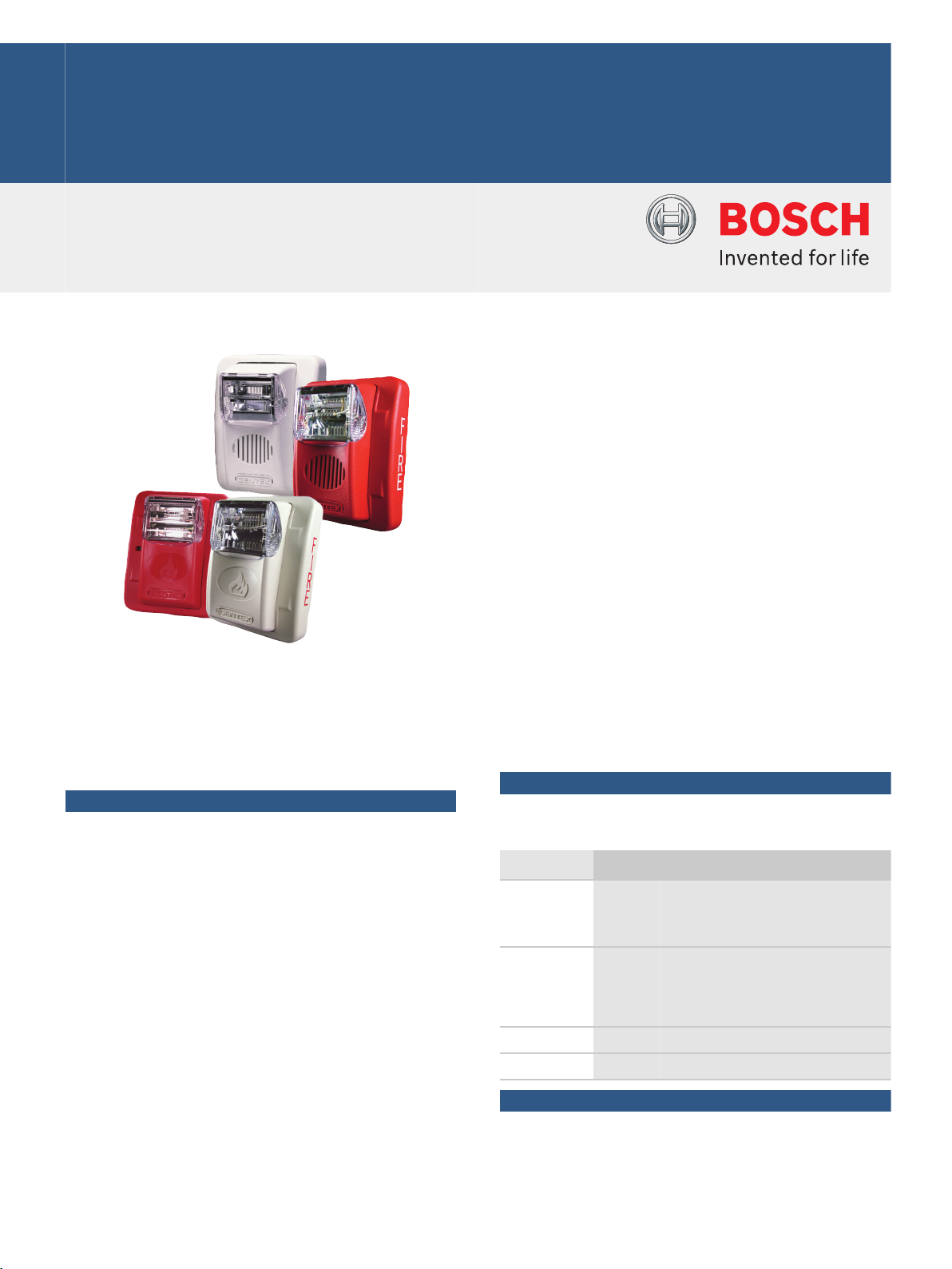
GE3‑24 24 V Strobes and Horn Strobes
www.boschsecurity.com
u Silence the horn while strobes flash
u Use the SuperSlide feature for easy testing
u Wide voltage range; 16 to 33 VDC or FWR
The Gentex Commander3 24 V Low‑frequency Strobes
(GES3‑24) and Horn Strobe (GEC3‑24) combinations
offer dependable alarms, a low current draw, and a
minimum flash rate of 1 Hz regardless of input voltage.
Functions
Easy Installation and Testing
The user can wire then install the entire system,
reducing installation and operating costs. Use the
SuperSlide feature to test supervision.
Horn Output
The horns provide a selection of high or low dBA. They
produce a peak sound of 100 dBA or greater at 10 ft
(3 m).
The horn offers a choice between a 2400 Hz (remote
signaling) tone or a low frequency mechanical
sounding (evacuation) tone where closed doors could
prevent hearing the other tone. The user can also
select either continuous or temporal Code 3 tone
output, and synchronize the temporal signal by using
an AVS Series Synchronization Module.
Strobe Output
Select from 15 cd, 30 cd, 60 cd, 75 cd, or 110 cd while
in the field using a sliding switch. The horn strobe
appliance with the AVS44, AVSM, or a compatible
u Many candela choices
u Select high or low frequency, high or low volume,
and temporal Code 3 or continuous tone pattern
control panel can silence the audible signal while
leaving the visible signal energized with the use of a
single pair of power wires.
Certifications and approvals
Gentex Corporation holds these Listings and
Approvals:
Region Certification
USA UL ULSZ: Audible Signal Appliances
(UL464), ULSZ7: Audible Signal Appliances Certified for Canada (cULus)
GEC3-24 models
UL GES3-24 models: UUKC: Signaling Ap-
pliances and Equipment for the Hearing
Impaired (UL1971), UVAV7: Visual Signal Appliances for Fire Protective Signaling Systems Certified for Canada (cUL)
FM
CSFM see our website
Installation/configuration notes
Compatible Products
The following products are compatible with the
GEC3‑24 Horn Strobes and GES3‑24 Strobes:
Page 2
2 | GE3‑24 24 V Strobes and Horn Strobes
Category Product ID Product Description
Control
D7022
1
Conventional FACP
Panels
D7024
2
Addressable FACP
D7024 Conventional FACP
D8024
D9124
D10024A
FPD-7024
3
3
3
2
Analog FACP
Addressable FACP
Analog FACP
Addressable FACP
FPD-7024 Conventional FACP
Modules AVS‑44 Synchronization module (red)
AVS44‑W Synchronization module (white)
AVSM‑R Synchronization module (red)
AVSM‑W Synchronization module (white)
1
The D7022 must be set for 24 VDC operation and
requires the AVS44 or AVSM Synchronization Modules
for synchronization.
2
When used with a D7039 Multiplex Expansion
Module, the FPD-7024 and D7024 become
addressable FACPs.
3
For synchronization, use the AVS44 or AVSM
Synchronization Modules with these control panels.
Mounting Considerations
Notice
Use the GE3‑24 horns and horn strobes for indoor
installations only.
These strobes and horn strobe combinations are
equipped with a four‑inch square metal mounting plate
that can be attached as follows:
Conduit
Applications
Surface
Mounted
Semi‑flush
Mounted
Single‑gang • •
Double‑gang • • •
Four‑inch square • • •
GSB • •
Also included is a locking mechanism that secures the
product to the bracket without any screws showing.
Shipping Information
The GEC3‑24 horn strobe models are delivered from
the factory set to the temporal lower frequency mode.
Wiring
The input terminals accept wires with diameters
between 18 AWG and 12 AWG (ISO 0.75 mm2 and
4 mm2).
Parts included
Quant. Component
1 Strobe or horn strobe with finish plate
1 Die‑cast mounting plate
1 Plastic test card
1 Hardware pack
1 Literature pack
Technical specifications
Electrical
Strobe Current
(maximum):
15 cd: 78 mA RMS; 113 mA FWR
30 cd: 96 mA RMS; 135 mA FWR
60 cd: 137 mA RMS; 186 mA FWR
75 cd: 180 mA RMS; 245 mA FWR
110 cd: 224 mA RMS; 313 mA FWR
Voltage Range: 16 to 33 VDC or FWR
Voltage (Input): 12 VDC or FWR nominal
Environmental
Relative Humidity Up to 93% non‑condensing
Temperature (Operating): +32°F to +120°F (0°C to +49°C)
Mechanical
Dimensions (HxWxD): 5.0 in. x 4.5 in. x 2.5 in. (12.7 cm x
11.4 cm x 6.4 cm)
Alarm Ratings
Horn (Continuous, 2400 Hz)
Audible Device Current
28 mA RMS; 48 mA FWR
(maximum):
Sound output (maximum range) at
10 ft (3 m):
High output: 86 dBA
Low output: 78 dBA
Horn (Continuous, Mechanical)
Audible Device Current
25 mA RMS; 44 mA FWR
(maximum):
Sound output (maximum range) at
10 ft (3 m):
High output: 84 dBA
Low output: 76 dBA
Horn (Temporal Code 3, 2400 Hz)
Audible Device Current
28 mA RMS; 48 mA FWR
(maximum):
Notice
Do not use these units in coded or pulsed
signaling circuits.
Sound output (maximum range) at
10 ft (3 m):
Horn (Temporal Code 3, Mechanical)
High output: 83 dBA
Low output: 75 dBA
Page 3

3 | GE3‑24 24 V Strobes and Horn Strobes
Audible Device Current
(maximum):
Sound output (maximum range) at
10 ft (3 m):
Chime (Continuous)
Audible Device Current
(maximum):
Sound output (maximum range) at
10 ft (3 m):
Chime (Temporal Code 3)
Audible Device Current
(maximum):
Sound output (maximum range) at
10 ft (3 m):
Whoop
Audible Device Current
(maximum):
Sound output (maximum range) at
10 ft (3 m):
25 mA RMS; 44 mA FWR
High output: 81 dBA
Low output: 73 dBA*
15 mA RMS; 30 mA FWR
High output: 71 dBA*
Low output: 68 dBA*
15 mA RMS; 30 mA FWR
High output: 71 dBA*
Low output: 68 dBA*
56 mA RMS; 62 mA FWR
High output: 83 dBA
Low output: 72 dBA*
* If you operate the horn in this mode at this voltage, it
does not meet the UL reverberant sound level required
for public mode fire protection service. These settings
are acceptable only for private mode fire alarm use.
Use the high output setting for public mode
application.
GES3‑24WR 24 VDC/FWR Strobe Unit
Red, 24 VDC strobe with field‑selectable intensities of
15 cd, 30 cd, 60 cd, 75 cd, or 110 cd.
Order number GES3-24WR
GES3‑24WW 24 VDC/FWR Strobe Unit
White, 24 VDC strobe with field‑selectable intensities
of 15 cd, 30 cd, 60 cd, 75 cd, or 110 cd.
Order number GES3-24WW
Accessories
AVS‑44 Synchronization Control Module (red)
Synchronization Control Module primarily for use with
the Gentex HS24 Series and ST24 Series notification
appliances.
Not Available.
Order number AVS-44
AVS44‑W Synchronization Control Module (white)
Synchronization Control Module primarily for use with
the Gentex HS24 Series and ST24 Series notification
appliances.
Not Available.
Order number AVS44-W
AVSM‑R Synchronization Control Module (red)
Synchronization module for use with all Gentex
synchronizable notification appliances except the
HS24 Series and the ST24 Series.
Not Available.
Order number AVSM-R
Notice
The sound output for the temporal (Code 3) tone
is rated lower because the time the horn is off is
averaged into the sound output rating. When the
horn is producing a tone in the Temporal mode its
sound pressure is the same as the Continuous
mode.
Trademarks
All hardware and software product names used in this
document are likely to be registered trademarks and
must be treated accordingly.
Ordering information
GEC3‑24WR 24 VDC/FWR Horn Strobe Unit
Red, 24 VDC horn strobe with field‑selectable
intensities of 15 cd, 30 cd, 60 cd, 75 cd, or 110 cd,
high or low frequency, high or low volume, and
temporal (Code 3) or continuous tone pattern.
Order number GEC3-24WR
GEC3‑24WW 24 VDC/FWR Horn Strobe Unit
White, 24 VDC horn strobe with field‑selectable
intensities of 15 cd, 30 cd, 60 cd, 75 cd, or 110 cd,
high or low frequency, high or low volume, and
temporal (Code 3) or continuous tone pattern.
Order number GEC3-24WW
AVSM‑W Synchronization Control Module (white)
Synchronization module for use with all Gentex
synchronizable notification appliances except the
HS24 Series and the ST24 Series.
Not Available.
Order number AVSM-W
GSB Surface Back Box (red)
5.6 in. x 4.6 in. x 1.5 in. (14.1 cm x 11.6 cm x 3.7 cm)
Order number GSB
Page 4

4 | GE3‑24 24 V Strobes and Horn Strobes
Represented by:
Americas: Europe, Middle East, Africa: Asia-Pacific: China: America Latina:
Bosch Security Systems, Inc.
130 Perinton Parkway
Fairport, New York, 14450, USA
Phone: +1 800 289 0096
Fax: +1 585 223 9180
security.sales@us.bosch.com
www.boschsecurity.us
Bosch Security Systems B.V.
P.O. Box 80002
5617 BA Eindhoven, The Netherlands
Phone: + 31 40 2577 284
Fax: +31 40 2577 330
emea.securitysystems@bosch.com
www.boschsecurity.com
Robert Bosch (SEA) Pte Ltd, Security
Systems
11 Bishan Street 21
Singapore 573943
Phone: +65 6571 2808
Fax: +65 6571 2699
apr.securitysystems@bosch.com
www.boschsecurity.asia
Bosch (Shanghai) Security Systems Ltd.
201 Building, No. 333 Fuquan Road
North IBP
Changning District, Shanghai
200335 China
Phone +86 21 22181111
Fax: +86 21 22182398
www.boschsecurity.com.cn
Robert Bosch Ltda Security Systems Division
Via Anhanguera, Km 98
CEP 13065-900
Campinas, Sao Paulo, Brazil
Phone: +55 19 2103 2860
Fax: +55 19 2103 2862
latam.boschsecurity@bosch.com
www.boschsecurity.com
© Bosch Security Systems 2014 | Data subject to change without notice
2719460107 | en, V2, 28. Aug 2014
 Loading...