

Page 1
Fire Alarm Systems | GES Low‑frequency Strobes
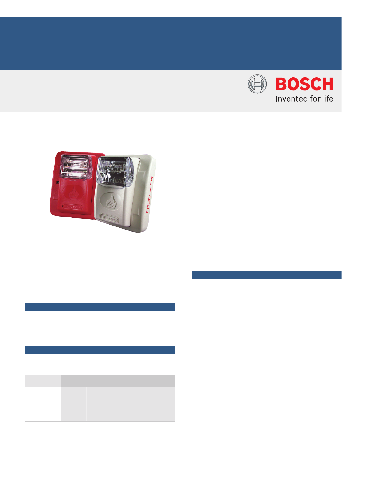
GES Low‑frequency Strobes
www.boschsecurity.com
u Use the SuperSlide feature for easy testing
u Wide voltage range; 16 to 33 VDC or FWR
u Many candela choices
The Gentex Commander² Low‑frequency Strobes
(GES) offer a dependable visual alarm, low current
draw, and a minimum flash rate of 1 Hz regardless of
input voltage.
Functions
Easy Installation and Testing
The user can wire then install the entire system,
reducing installation and operating costs. Use the
SuperSlide feature to test supervision.
Certifications and approvals
Gentex Corporation holds these Listings and
Approvals:
Region
Certification
USA UL UUKC_S5405 - Signaling Appliances and
Equipment for the Hearing Impaired
FM
CSFM 7125-0569-0123
u Wire then install the entire system
u Use the GSB Surface Back Box for easy mounting
Installation/configuration notes
Compatible Products
The following products are compatible with the GES
Strobes:
Category Product ID Product Description
Control Panels D7022
D7024
1
2
Conventional FACP
Addressable FACP
D7024 Conventional FACP
D8024
D9124
D10024A
FPD-7024
3
3
3
2
Analog FACP
Addressable FACP
Analog FACP
Addressable FACP
FPD-7024 Conventional FACP
Modules AVS‑44 Synchronization module (red)
AVS44‑W Synchronization module (white)
AVSM‑R Synchronization module (red)
AVSM‑W Synchronization module (white)
Page 2
2 | GES Low‑frequency Strobes
1
The D7022 must be set for 24 VDC operation and
requires the AVS44 or AVSM Synchronization Modules
for synchronization.
2
When used with a D7039 Multiplex Expansion
Module, the D7024 and FPD-7024 become
addressable FACPs.
3
For synchronization, use the AVS44 or AVSM
Synchronization Modules with these control panels.
Mounting Considerations
Notice
Use the strobes for indoor installations only.
The strobes are equipped with a four‑inch square
mounting plate that can be attached as follows:
Conduit
Applications
Single‑gang • •
Double‑gang • • •
Four‑inch square • • •
GSB • •
Surface
Mounted
Semi‑flush
Mounted
Also included is a locking mechanism that secures the
product to the bracket without any screws showing.
Wiring
Notice
Do not use these units in coded or pulsed
signaling circuits.
The input terminals accept wires with diameters
between 18 AWG and 12 AWG (ISO 0.75 mm2 and
4 mm2).
Parts included
Quant. Component
1 Horn with finish plate
1 Die‑cast mounting plate
1 Plastic test card
1 Hardware pack
1 Literature pack
Technical specifications
Electrical
Voltage Range: 16 VDC or FWR to 33 VDC or FWR
Voltage (Input): 24 VDC or VFWR nominal
Mechanical
Dimensions
(H x W x D):
5.0 in. x 4.5 in. x 2.5 in.
(12.7 cm x 11.4 cm x 6.4 cm)
Strobe Current Ratings (maximum)
15 cd: 78 mA RMS, 113 mA FWR
15/75 cd: 96 mA RMS, 135 mA FWR
30 cd: 96 mA RMS, 135 mA FWR
60 cd: 137 mA VDC, 186 mA FWR
75 cd: 180 mA VDC, 245 mA FWR
110 cd: 244 mA VDC, 313 mA FWR
Trademarks
All hardware and software product names used in this
document are likely to be registered trademarks and
must be treated accordingly.
Ordering information
GES24-15WR 15 cd Strobe (red)
Red, 24 VDC 15 cd strobe
Not Available.
Order number GES24-15WR
GES24-15WW 15 cd Strobe (white)
White, 24 VDC 15 cd strobe
Not Available.
Order number GES24-15WW
GES24‑15/75WW 15/75 cd Strobe (white)
White, 24 VDC 15/75 cd strobe.
Not Available.
Order number GES24-15/75WW
GES24-30WR 30 cd Strobe (red)
Red, 24 VDC 30 cd strobe
Not Available.
Order number GES24-30WR
GES24-30WW 30 cd Strobe (white)
White, 24 VDC 30 cd strobe
Not Available.
Order number GES24-30WW
GES24-60WR 60 cd Strobe (red)
Red, 24 VDC 60 cd strobe
Not Available.
Order number GES24-60WR
GES24-60WW 60 cd Strobe (white)
White, 24 VDC 60 cd strobe
Not Available.
Order number GES25-60WW
Environmental
Relative Humidity Up to 93% non‑condensing
Temperature
(Operating):
+32°F to +120°F (0°C to +49°C)
GES24-75WR 75 cd Strobe (red)
Red, 24 VDC 75 cd strobe
Not Available.
Order number GES24-75WR
Page 3

3 | GES Low‑frequency Strobes
Represented by:
Americas: Europe, Middle East, Africa: Asia-Pacific: China: America Latina:
Bosch Security Systems, Inc.
130 Perinton Parkway
Fairport, New York, 14450, USA
Phone: +1 800 289 0096
Fax: +1 585 223 9180
security.sales@us.bosch.com
www.boschsecurity.us
Bosch Security Systems B.V.
P.O. Box 80002
5617 BA Eindhoven, The Netherlands
Phone: + 31 40 2577 284
Fax: +31 40 2577 330
emea.securitysystems@bosch.com
www.boschsecurity.com
Robert Bosch (SEA) Pte Ltd, Security
Systems
11 Bishan Street 21
Singapore 573943
Phone: +65 6571 2808
Fax: +65 6571 2699
apr.securitysystems@bosch.com
www.boschsecurity.asia
Bosch (Shanghai) Security Systems Ltd.
201 Building, No. 333 Fuquan Road
North IBP
Changning District, Shanghai
200335 China
Phone +86 21 22181111
Fax: +86 21 22182398
www.boschsecurity.com.cn
Robert Bosch Ltda Security Systems Division
Via Anhanguera, Km 98
CEP 13065-900
Campinas, Sao Paulo, Brazil
Phone: +55 19 2103 2860
Fax: +55 19 2103 2862
latam.boschsecurity@bosch.com
www.boschsecurity.com
© Bosch Security Systems 2014 | Data subject to change without notice
2719947659 | en, V2, 01. Oct 2014
GES24-75WW 75 cd Strobe (white)
White, 24 VDC 75 cd strobe
Not Available.
Order number GES24-75WW
GES24-110WR 110 cd Strobe (red)
Red, 24 VDC 110 cd strobe
Not Available.
Order number GES24-110WR
GES24-110WW 110 cd Strobe (white)
White, 24 VDC 110 cd strobe
Not Available.
Order number GES24-110FW 110 cd Strobe (white)
Accessories
AVS‑44 Synchronization Control Module (red)
Order number AVS-44
AVS44‑W Synchronization Control Module (white)
Order number AVS44-W
AVSM‑R Synchronization Control Module (red)
Synchronization module for use with all Gentex
synchronizable notification appliances except the
HS24 Series and the ST24 Series.
Not Available.
Order number AVSM-R
AVSM‑W Synchronization Control Module (white)
Synchronization module for use with all Gentex
synchronizable notification appliances except the
HS24 Series and the ST24 Series.
Not Available.
Order number AVSM-W
GSB Surface Back Box (red)
5.6 in. x 4.6 in. x 1.5 in. (14.1 cm x 11.6 cm x 3.7 cm)
Order number GSB
 Loading...