

Bosch GES3-24WW, GEC3-24WW, GEC3-24WR, GEC24-15, GES24-15WR Installation Manual
...
III. MOUNTING, ROUGH-IN BOX AND RUN WIRING
This unit is designed for mounting to most single gang boxes, 4" square outlet boxes, 2-gang masonry boxes or non-metallic 2-gang switch boxes.
Conduit entrance to boxes should be selected to insure sufficient wiring clearance.
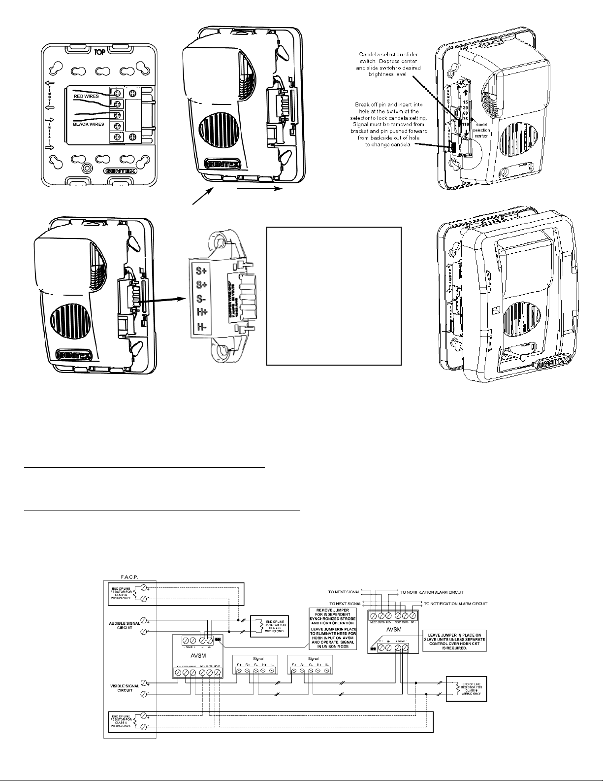
1. Mount a box for each remote signaling appliance. Screw bracket onto box. Insert signal into bracket and slide to the right firmly into the terminal block
receptacle. Place housing over mounted assembly and screw together with single screw at the bottom of the signal. Cover screw with plastic tab.
2. Run a minimum 18 gauge insulated 2 or more conductor cable.
Attention: Wiring should be connected to mounting bracket prior to mounting signal. Incoming positive power lead must be broken and each
lead is to be inserted into each of the top two terminals. If two power runs are made to the signal, one for the strobe and one for the horn, only
one of the runs must have its positive lead broken and placed under the two separate top terminals. A barrier is provided to prevent both leads
from being placed under the same terminal.
GEC, GEH & GES
SERIES
UL 1971 COMPLIANT
CAN/ULC S526-M87 Compliant
VISIBLE AND/OR AUDIBLE SIGNALING APPLIANCES
I. INTRODUCTION
The Gentex Model GEC/GES/GEH, horn/strobe, strobe or horn, is a high quality audible and/or visible signaling appliance. The high intensity strobe utilizes a
Xenon flash tube that generates a high-intensity flash visible from all angles. This appliance is intended to provide a visible, audible or audible/visible,
depending on the model, notification signal for the purpose of life safety and property protection. The GEC3 and GES3 are provided with a slider switch which
allows for candela selection at the installation site. The intensities which can be selected are 15Cd, 30Cd, 60Cd, 75Cd, or 110Cd. This appliance is ideal for
any occupancy that requires notification appliances per the applicable building or fire code or wherever dependable alarms are required. The strobe is listed in
compliance with UL 1971, Signaling Appliances for the Hearing Impaired and CAN/UL S526-M87 Visible Signal Devices for Fire Alarm Systems (15/75Cd model
is additionally listed in compliance with UL1638).
II. LOCATION
This appliance is intended for use in Fire Alarm Systems and is to be installed in accordance with this manual, the recommendation of the local authorities
having jurisdiction, and other NFPA documents that provide standards on notification appliances for protective signaling systems. The GEC/GES is intended for
indoor installations only. This appliance is not weatherproof for outdoor or drip proof applications.
Wall mounted strobe and horn/strobe appliances shall have their entire lens at heights above the finished floor of not less than 80 in. (2m) and not greater than
96 in. (2.4m)**. Spacing shall be in accordance with Table A. If a room configuration is not square, the room size that will entirely encompass the room or
subdivide the room into multiple squares shall be used.
Wall mounted horn only appliances shall have their tops above the finished floors at heights of not less than 90in. (2.30m) and below the finished ceilings at
heights of not less than 6 in. (152mm). Different mounting heights shall be permitted by the AHJ provided the sound pressure level requirements of NFPA 72 are
met.
**Effective Intensity Requirements
for Sleeping Areas
Visible Notification Appliance
Distance from Ceiling to Top of Lens Intensity
greater than or equal to 24" 110cd
less than 24" 177cd
1
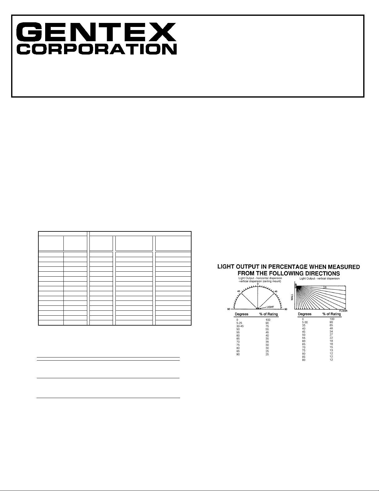
Two Lights per Four Lights per
Meters Feet One Light Room (Located on Room (One Light
per Room Opposite Walls) per Wall)
6.10 x 6.10 20 x 20 15 NA NA
8.53 x 8.53 28 x 28 30 Unknown Unknown
9.14 x 9.14 30 x 30 34 15 NA
12.2 x 12.2 40 x 40 60 30 15
13.7 x 13.7 45 x 45 75 Unknown Unknown
15.2 x 15.2 50 x 50 94 60 30
16.5 x 16.5 54 x 54 110 Unknown Unknown
18.3 x 18.3 60 x 60 135 95 30
21.3 x 21.3 70 x 70 184 95 60
24.4 x 24.4 80 x 80 240 135 60
27.4 x 27.4 90 x 90 304 185 95
30.5 x 30.5 100 x 100 375 240 95
33.5 x 33.5 110 x 110 455 240 135
36.6 x 36.6 120 x 120 540 305 135
39.6 x 39.6 130 x 130 635 375 185
Maximum Room Size
Minimum Required Light Output (Eff ectiv e Intensity, Cd)
NA = Not allowable.
Table A
CAUTION: A jumper card is provided to test for correct wiring in the supervisory mode only. DO NOT pass alarm current through the jumper.
NOTE: All strobes are designed to flash as specified with continuous applied voltage. This appliance is not recommended for use on coded or pulsing
signaling circuits. However, use of the AVSM control module is permitted to synchronize the strobe and/or mute the horn.
IV. WIRING
Wiring for independent synchronized strobes and horn.
Using this method you may:
· Use only two wires to synchronize the temporal horn and strobe with the ability to mute the horn (place switches 1 and 2 up on the GEC).
· Mute the horn only when the temporal horn option has been selected.
Wiring for synchronized parallel (unison) horn/strobe operation.
Using this method you may:
· Use only two wires to synchronize the temporal horn and strobe without the ability to mute the horn (place switches 1 and 2 up on the GEC).
· Choose either temporal or continuous horn with the temporal horn synchronized.
· Also wire the control module (AVSM) to only the strobe input power terminals, set the horn to continuous mode and power it from a coded source. NOTE:
For this option, switches 1 and 2 on the GEC (Fig.1) must be down to isolate power to the audible and visible portion of the circuit.
2
(GEC3 & GES3 ONLY)
CheckmateTMVoltage
Verification Access Holes:
It is often necessary to confirm the voltage
drop along a line of devices. The access
holes are provided in the back of the terminal block to allow the voltage to be
measured directly without removing the
device. Typically this would be done at the
end of the line to confirm design criteria.
Most measurements will be taken using
the S+ and S- locations although access is
provided to other locations.
NOTE: Care should be taken to not
short the test probes.
 Loading...