

Bosch GE-50576-A Operating Manual
CHECK•LINE
®
BY ELECTROMATIC
MODEL GE-50576-A
BELT TENSION TESTER
Operating Manual

–1 –
TABLE OF CONTENTS
1.0 Overview .................................................................................................................. 02
2.0 GE-50576-A Components ........................................................................................ 03
3.0 Display ...................................................................................................................... 04
4.0 Operation Instructions .............................................................................................. 05
5.0 Set-up ........................................................................................................................ 07
6.0 Noise Cancelation ..................................................................................................... 08
7.0 Charging Instructions ............................................................................................... 09
8.0 Testing Belts ............................................................................................................. 10
9.0 Maintenance ............................................................................................................. 10
10.0 Technical Specications and Certications ............................................................. 11
11.0 Warranty ................................................................................................................... 12
SAFETY PRECAUTIONS
Please read this section carefully to ensure safe operation.
• Do not drop or allow GE-50576-A to be hit.
• Remove the microphone from GE-50576-A after use and place in the storage case.
• Do not use the tool near ammable substances.
• Do not use the tool near water or other liquids.
• When performing the test in vehicle, let the engine cool down before testing.
CAUTION!
• Do not store in a humid area.
• Do not place heavy objects on the GE-50576-A.
• Do not wash the tool with liquid cleaners. Wipe with a clean, dry cloth.
• Store the tool in an area away from heat or direct sunlight.
• GE-50576-A goes into sleep mode after 5 minutes without operation, but does
not power off. Users should perform the power-off operation manually after
testing is complete.
– 2 –
1.0 OVERVIEW
This manual explains the operation of GE-50576-A. Please read it carefully before using
the GE-50576-A.
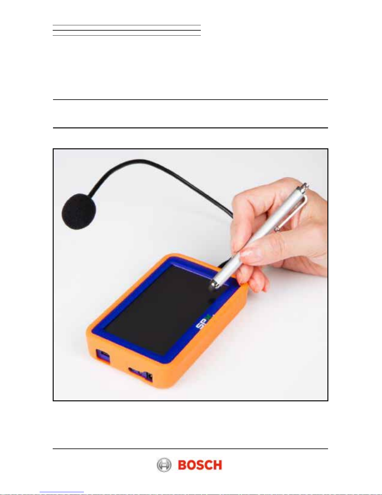
The GE-50576-A Acoustic Belt Tension Tester enables belt tension measurement with
no direct contact. It measures the belt tension of engine accessory belt systems and
Electronic Power Steering (EPS) steering racks. When the microphone is held close to
the belt, and the belt is plucked, belt vibration is captured by the microphone, and the
frequency is displayed.
For more detailed procedures, please consult published service information for the
vehicle or component being serviced.
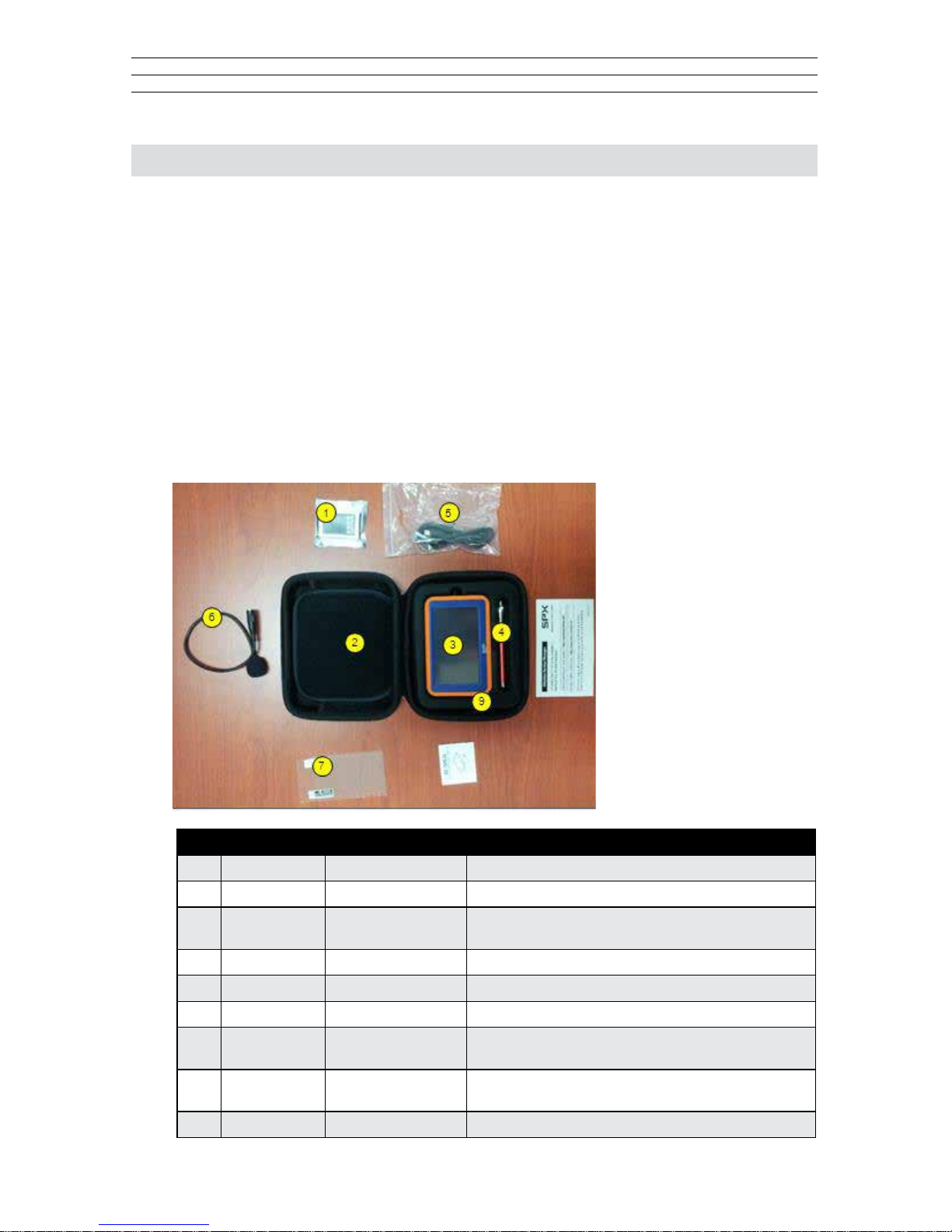
1.1 Complete Kit
The GE-50576-A is
supplied as a complete
kit that contains the
components outlined
in the table below and
identied in the photo.
No. Item No. Description Model Name / Specification
1 GE-50576-05 Li-Ion Battery 3.7V, 800mA
2 GE-50576-06 Storage Case Material: Plastic / Dimensions: 160 x 100 x 60 mm
3 GE-50576-01 Accoustic
Belt Tension Tester
Dimensions (approx): 10 x 75 x 20 mm
4 GE-50576-04 Touch Pen General Resistance touch Pen
5 GE-50576-03 USB Cable General USB Cable
6 GE-50576-02 Microphone Uni-Directional Type, 30CM Flexible Type
7 GE-50576-07 LCD Protection
Film (not shown)
Protection Film / 4.3 inch LCD
8 GE-50576-08 User Manual
(not shown)
User Operation Manual
9 GE-50576-09 Protective Boot Dimensions (approx): 10 x 75 x 20 mm
– 3 –
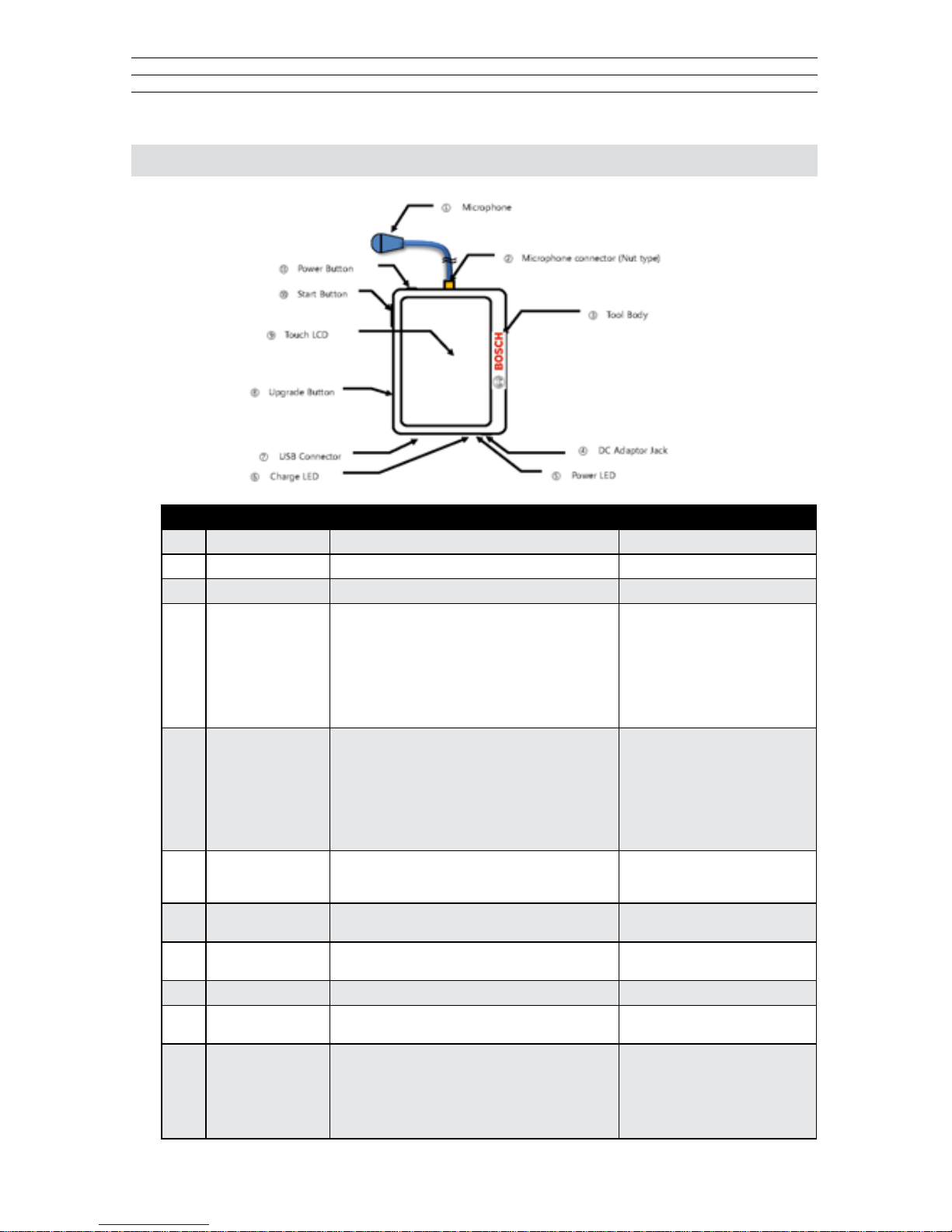
2.0 COMPONENTS
No. Name Description Remark
1 Microphone Flexible shaft directional microphone
2 MIC Connector Nut type microphone connector
3 Tool Body Tool Body
4 DC Adaptor Jack AD/DC converter adaptor jack
DC 12V, 2A output is recommended when USB
charging is not available
• Power On: Blinks Green for
4 seconds, then turns solid Green
• Normal Status: Solid Green
• Red Blink: Sleep mode – up to
5 minutes
• Green/Red Blink: Timed out –
Power must be turned Off, then
back On
5 Power LED LED displays power status • Power on: Blinks Green for
4 seconds, then turns solid Green
• Normal status: Solid Green
• Red Blink: Sleep mode (up to
5 minutes)
• Green/Red Blink: Timed out –
Power must be turned Off, then
back On
6 Charge LED Displays charge status. Note: If the unit is powered
on while being charged (via DC adapter or USB
cable) the charge LED turns green.
• Red: Charging
• Blinking Red: Low Battery
• Green: Charge complete
7 USB Connector USB connection port for charging
& rmware update
8 Update Button Depress the update button through the hole in the
case when software updates are required.
9 Touch LCD Resistive touch panel LCD display 3.4", 480RGB, 272 dots
10 Start Button Mechanical start button Operation is the same as
on the main display
11 Power Button Mechanical Power on/off (Sliding type)
• Power On : Slide left to turn on
• Power Off : Slide right to turn off
• Auto Sleep mode: Automatic LCD power-off
after 5 minutes without operation. Wakes up when
the screen is touched.
Sleep mode is not the same as
Power Off. The processor is
active, but the display is off.
– 4 –
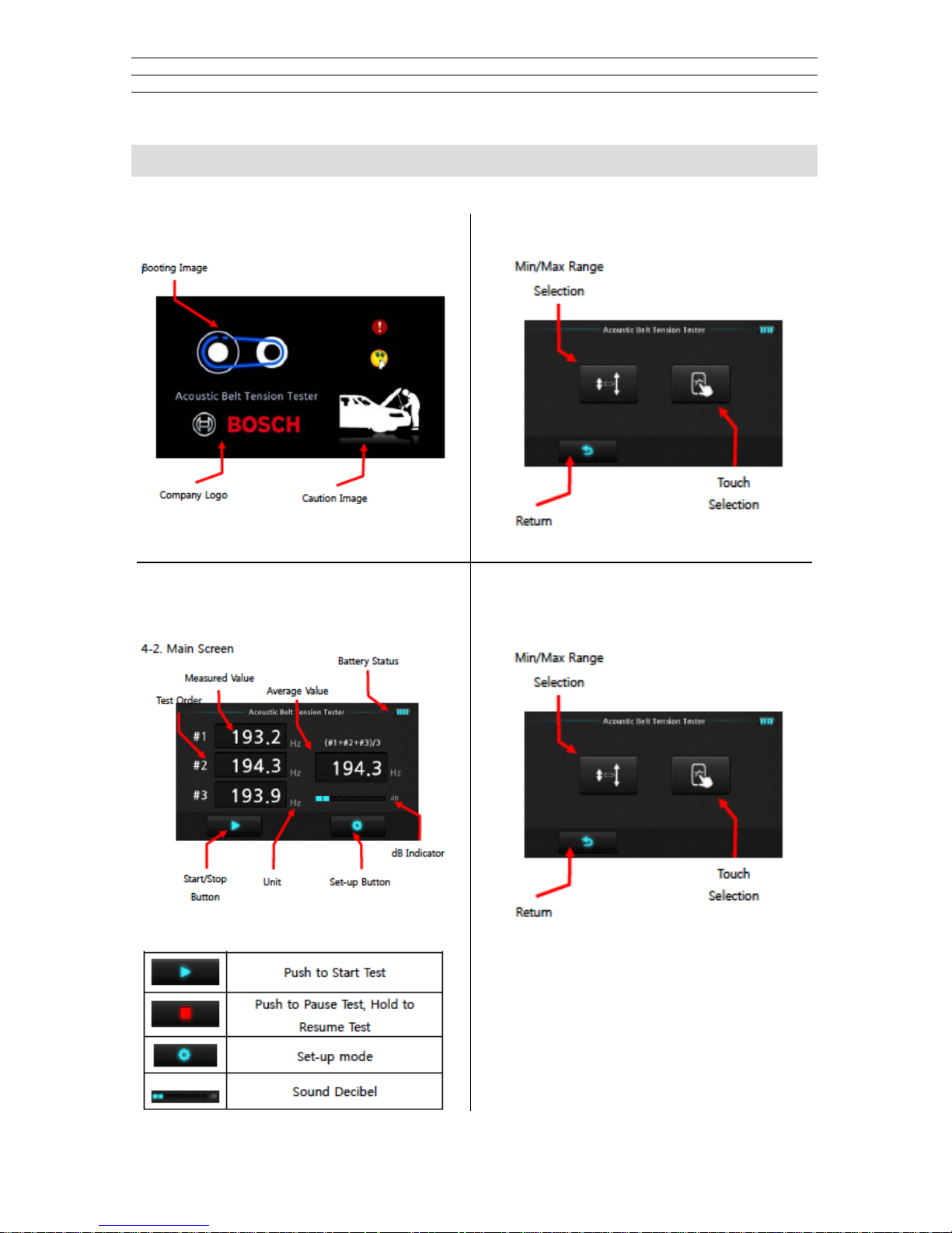
3.0 DISPLAY
3.1 Booting Screen
3.2 Main Screen
3.3 Set-up Selection Screen
3.4 Min/Max Range Setting
 Loading...