

Bosch GBH Professional 36 V-LI Plus, GBH Professional 36 VF-LI Plus User Manual
ςТЎϩХʉ ЌТϾϦφЍʉ ʌμВТЎϺυ
ΖЎϩʉ ˒μВЖЙʉʓ ИͳϞφЁʑ
OBJ_BUCH-283-013.book Page 1 Thursday, September 29, 2016 8:27 AM
Robert Bosch Power Tools GmbH
70538 Stuttgart
GERMANY
www.bosch-pt.com
GBH Professional
1 609 92A 2CS (2016.09) T / 274
36 V-LI Plus | 36 VF-LI Plus
de Originalbetriebsanleitung
en Original instructions
fr Notice originale
es Manual original
pt Manual original
it Istruzioni originali
nl Oorspronkelijke
gebruiksaanwijzing
da Original brugsanvisning
sv Bruksanvisning i original
no Original driftsinstruks
fi Alkuperäiset ohjeet
el Πρωτότυπο οδηγιών χρήσης
tr Orijinal işletme talimatı
pl Instrukcja oryginalna
cs Původní návod k používání
sk Pôvodný návod na použitie
hu Eredeti használati utasítás
ru Оригинальное руководство по
эксплуатации
uk Оригінальна інструкція з
експлуатації
kk Пайдалану нұсқаулығының
түпнұсқасы
ro Instrucţiuni originale
bg Оригинална инструкция
mk Оригинално упатство за работа
sr Originalno uputstvo za rad
sl Izvirna navodila
hr Originalne upute za rad
et Algupärane kasutusjuhend
lv Instrukcijas oriģinālvalodā
lt Originali instrukcija
ar
fa
OBJ_BUCH-283-013.book Page 2 Thursday, September 29, 2016 8:28 AM
2 |
Deutsch. . . . . . . . . . . . . . . . . . . . . . . . . . . . . . . . . . . . . . . . . Seite 6
English . . . . . . . . . . . . . . . . . . . . . . . . . . . . . . . . . . . . . . . . . . Page 14
Français . . . . . . . . . . . . . . . . . . . . . . . . . . . . . . . . . . . . . . . . . Page 23
Español . . . . . . . . . . . . . . . . . . . . . . . . . . . . . . . . . . . . . . . . Página 31
Português . . . . . . . . . . . . . . . . . . . . . . . . . . . . . . . . . . . . . . Página 41
Italiano . . . . . . . . . . . . . . . . . . . . . . . . . . . . . . . . . . . . . . . . Pagina 49
Nederlands . . . . . . . . . . . . . . . . . . . . . . . . . . . . . . . . . . . . . Pagina 58
Dansk . . . . . . . . . . . . . . . . . . . . . . . . . . . . . . . . . . . . . . . . . . . Side 67
Svenska . . . . . . . . . . . . . . . . . . . . . . . . . . . . . . . . . . . . . . . . . Sida 74
Norsk. . . . . . . . . . . . . . . . . . . . . . . . . . . . . . . . . . . . . . . . . . . . Side 82
Suomi . . . . . . . . . . . . . . . . . . . . . . . . . . . . . . . . . . . . . . . . . . . Sivu 89
Ελληνικά . . . . . . . . . . . . . . . . . . . . . . . . . . . . . . . . . . . . . . . Σελίδα 97
Türkçe . . . . . . . . . . . . . . . . . . . . . . . . . . . . . . . . . . . . . . . . . . Sayfa 106
Polski . . . . . . . . . . . . . . . . . . . . . . . . . . . . . . . . . . . . . . . . . Strona 114
Česky . . . . . . . . . . . . . . . . . . . . . . . . . . . . . . . . . . . . . . . . . Strana 123
Slovensky . . . . . . . . . . . . . . . . . . . . . . . . . . . . . . . . . . . . . . Strana 131
Magyar . . . . . . . . . . . . . . . . . . . . . . . . . . . . . . . . . . . . . . . . . Oldal 139
Русский . . . . . . . . . . . . . . . . . . . . . . . . . . . . . . . . . . . . Страница 148
Українська . . . . . . . . . . . . . . . . . . . . . . . . . . . . . . . . . . . Сторінка 158
Қазақша . . . . . . . . . . . . . . . . . . . . . . . . . . . . . . . . . . . . . . . . . . Бет 167
Română. . . . . . . . . . . . . . . . . . . . . . . . . . . . . . . . . . . . . . . . Pagina 177
Български . . . . . . . . . . . . . . . . . . . . . . . . . . . . . . . . . . Страница 185
Македонски . . . . . . . . . . . . . . . . . . . . . . . . . . . . . . . . . . . Страна 195
Srpski . . . . . . . . . . . . . . . . . . . . . . . . . . . . . . . . . . . . . . . . . Strana 204
Slovensko . . . . . . . . . . . . . . . . . . . . . . . . . . . . . . . . . . . . . . . Stran 211
Hrvatski. . . . . . . . . . . . . . . . . . . . . . . . . . . . . . . . . . . . . . . Stranica 219
Eesti . . . . . . . . . . . . . . . . . . . . . . . . . . . . . . . . . . . . . . . . Lehekülg 227
Latviešu . . . . . . . . . . . . . . . . . . . . . . . . . . . . . . . . . . . . . . Lappuse 234
Lietuviškai. . . . . . . . . . . . . . . . . . . . . . . . . . . . . . . . . . . . . Puslapis 243
. . . . . . . . . . . . . . . . . . . . . . . . . . . . . . 259
. . . . . . . . . . . . . . . . . . . . . . . . . . . . . . 268
. . . . . . . . . . . . . . . . . . . . . . . . . . . . . . . . . . . . . . . . . . . . . . . . I
1 609 92A 2CS | (29.9.16) Bosch Power Tools
OBJ_BUCH-283-013.book Page 3 Thursday, September 29, 2016 8:28 AM
3 |
1
GBH 36 VF-LI Plus
2
5
4
3
17
GBH 36 V-LI Plus
7
8
9
10
6
11
12
13
14
15
16
9
16
A B
18
19
20
21
16
1 609 92A 2CS | (29.9.16) Bosch Power Tools
OBJ_BUCH-283-013.book Page 4 Thursday, September 29, 2016 8:28 AM
4 |
C
23
22
GBH 36 V-LI Plus
E
25
2
24
D
5
6
GBH 36 VF-LI Plus
F
26
(2x/
GBH 36 VF-LI Plus
G
1 609 92A 2CS | (29.9.16) Bosch Power Tools
3x)
H
5
GBH 36 V-LI Plus
23
27
OBJ_BUCH-283-013.book Page 5 Thursday, September 29, 2016 8:28 AM
5 |
I
GBH 36 V-LI Plus
K
29
28
J
GBH 36 VF-LI Plus
L
29
28
30
GBH 36 VF-LI Plus
M
1 609 92A 2CS | (29.9.16) Bosch Power Tools
17
3
X
15
N
31
OBJ_BUCH-283-013.book Page 6 Thursday, September 29, 2016 8:34 AM
6 | Deutsch
Wenn der Betrieb des Elektrowerkzeuges in feuchter
Deutsch
Sicherheitshinweise
Allgemeine Sicherheitshinweise für Elektrowerkzeuge
WARNUNG
haltung der Sicherheitshinweise und Anweisungen können
elektrischen Schlag, Brand und/oder schwere Verletzungen
verursachen.
Bewahren Sie alle Sicherheitshinweise und Anweisungen
für die Zukunft auf.
Der in den Sicherheitshinweisen verwendete Begriff „Elektrowerkzeug“ bezieht sich auf netzbetriebene Elektrowerkzeuge
(mit Netzkabel) und auf akkubetriebene Elektrowerkzeuge
(ohne Netzkabel).
Arbeitsplatzsicherheit
Halten Sie Ihren Arbeitsbereich sauber und gut be-
leuchtet. Unordnung oder unbeleuchtete Arbeitsbereiche
können zu Unfällen führen.
Arbeiten Sie mit dem Elektrowerkzeug nicht in explo-
sionsgefährdeter Umgebung, in der sich brennbare
Flüssigkeiten, Gase oder Stäube befinden. Elektrowerk-
zeuge erzeugen Funken, die den Staub oder die Dämpfe
entzünden können.
Halten Sie Kinder und andere Personen während der
Benutzung des Elektrowerkzeugs fern. Bei Ablenkung
können Sie die Kontrolle über das Gerät verlieren.
Elektrische Sicherheit
Der Anschlussstecker des Elektrowerkzeuges muss in
die Steckdose passen. Der Stecker darf in keiner Weise
verändert werden. Verwenden Sie keine Adapterstecker gemeinsam mit schutzgeerdeten Elektrowerkzeugen. Unveränderte Stecker und passende Steckdosen ver-
ringern das Risiko eines elektrischen Schlages.
Vermeiden Sie Körperkontakt mit geerdeten Oberflä-
chen wie von Rohren, Heizungen, Herden und Kühlschränken. Es besteht ein erhöhtes Risiko durch elektri-
schen Schlag, wenn Ihr Körper geerdet ist.
Halten Sie Elektrowerkzeuge von Regen oder Nässe
fern. Das Eindringen von Wasser in ein Elektrowerkzeug
erhöht das Risiko eines elektrischen Schlages.
Zweckentfremden Sie das Kabel nicht, um das Elektro-
werkzeug zu tragen, aufzuhängen oder um den Stecker
aus der Steckdose zu ziehen. Halten Sie das Kabel fern
von Hitze, Öl, scharfen Kanten oder sich bewegenden
Geräteteilen. Beschädigte oder verwickelte Kabel erhö-
hen das Risiko eines elektrischen Schlages.
Wenn Sie mit einem Elektrowerkzeug im Freien arbei-
ten, verwenden Sie nur Verlängerungskabel, die auch
für den Außenbereich geeignet sind. Die Anwendung
eines für den Außenbereich geeigneten Verlängerungskabels verringert das Risiko eines elektrischen Schlages.
Lesen Sie alle Sicherheitshinweise und
Anweisungen. Versäumnisse bei der Ein-
Umgebung nicht vermeidbar ist, verwenden Sie einen
Fehlerstromschutzschalter. Der Einsatz eines Fehler-
stromschutzschalters vermindert das Risiko eines elektrischen Schlages.
Sicherheit von Personen
Seien Sie aufmerksam, achten Sie darauf, was Sie tun,
und gehen Sie mit Vernunft an die Arbeit mit einem
Elektrowerkzeug. Benutzen Sie kein Elektrowerkzeug,
wenn Sie müde sind oder unter dem Einfluss von Drogen, Alkohol oder Medikamenten stehen. Ein Moment
der Unachtsamkeit beim Gebrauch des Elektrowerkzeuges
kann zu ernsthaften Verletzungen führen.
Tragen Sie persönliche Schutzausrüstung und immer
eine Schutzbrille. Das Tragen persönlicher Schutzausrüs-
tung, wie Staubmaske, rutschfeste Sicherheitsschuhe,
Schutzhelm oder Gehörschutz, je nach Art und Einsatz des
Elektrowerkzeuges, verringert das Risiko von Verletzungen.
Vermeiden Sie eine unbeabsichtigte In
Vergewissern Sie sich, dass das Elektrowerkzeug ausgeschaltet ist, bevor Sie es an die Stromversorgung und/
oder den Akku anschließen, es aufnehmen oder tragen.
Wenn Sie beim Tragen des Elektro
am Schalter haben oder das Gerät eingeschaltet an die
Stromversorgung anschließen, kann dies zu Unfällen führen.
Entfernen Sie Einstellwerkzeuge oder Schrauben-
schlüssel, bevor Sie das Elektrowerkzeug einschalten.
Ein Werkzeug oder Schlüssel, der sich in einem drehenden
Geräteteil befindet, kann zu Verletzungen führen.
Vermeiden Sie eine abnormale Körperhaltung. Sorgen
Sie für einen sicheren Stand und halten Sie jederzeit
das Gleichgewicht. Dadurch können Sie das Elektrowerk-
zeug in unerwarteten Situationen besser kontrollieren.
Tragen Sie geeignete Kleidung. Tragen Sie keine weite
Kleidung oder Schmuck. Halten Sie Haare, Kleidung
und Handschuhe fern von sich bewegenden Teilen.
Lockere Kleidung, Schmuck oder lange Haare können von
sich bewegenden Teilen erfasst werden.
Wenn Staubabsaug- und -auffangeinrichtungen mon-
tiert werden können, vergewissern Sie sich, dass diese
angeschlossen sind und richtig verwendet werden. Ver-
wendung einer Staubabsaugung kann Gefährdungen
durch Staub verringern.
Verwendung und Behandlung des Elektrowerkzeuges
Überlasten Sie das Gerät nicht. Verwenden Sie für Ihre
Arbeit das dafür bestimmte Elektrowerkzeug. Mit dem
passenden Elektrowerkzeug arbeiten Sie besser und
sicherer im angegebenen Leistungsbereich.
Benutzen Sie kein Elektrowerkzeug, dessen Schalter de-
fekt ist. Ein Elektrowerkzeug, das sich nicht mehr ein- oder
ausschalten lässt, ist gefährlich und muss repariert werden.
Ziehen Sie den Stecker aus der Steckdose und/oder
entfernen Sie den Akku, bevor Sie Geräteeinstellungen
vornehmen, Zubehörteile wechseln oder das Gerät
weglegen. Diese Vorsichtsmaßnahme verhindert den
unbeabsichtigten Start des Elektrowerkzeuges.
betriebnahme.
werkzeuges den Finger
1 609 92A 2CS | (29.9.16) Bosch Power Tools
OBJ_BUCH-283-013.book Page 7 Thursday, September 29, 2016 8:34 AM
Bewahren Sie unbenutzte Elektrowerkzeuge außer-
halb der Reichweite von Kindern auf. Lassen Sie Personen das Gerät nicht benutzen, die mit diesem nicht vertraut sind oder diese Anweisungen nicht gelesen
haben. Elektrowerkzeuge sind gefährlich, wenn sie von
unerfahrenen Personen benutzt werden.
Pflegen Sie Elektrowerkzeuge mit Sorgfalt. Kontrollie-
ren Sie, ob bewegliche Teile einwandfrei funktionieren
und nicht klemmen, ob Teile gebrochen oder so beschädigt sind, dass die Funktion des Elektrowerkzeuges beeinträchtigt ist. Lassen Sie beschädigte Teile vor
dem Einsatz des Gerätes reparieren. Viele Unfälle haben
ihre Ursache in schlecht gewarteten Elektrowerkzeugen.
Halten Sie Schneidwerkzeuge scharf und sauber.
Sorgfältig gepflegte Schneidwerkzeuge mit scharfen
Schneidkanten verklemmen sich weniger und sind leichter
zu führen.
Verwenden Sie Elektrowerkzeug, Zubehör, Einsatz-
werkzeuge usw. entsprechend diesen Anweisungen.
Berücksichtigen Sie dabei die Arbeitsbedingungen und
die auszuführende Tätigkeit. Der Gebrauch von Elektro-
werkzeugen für andere als die vorgesehenen Anwendungen kann zu gefährlichen Situationen führen.
Verwendung und Behandlung des Akkuwerkzeuges
Laden Sie die Akkus nur mit Ladegeräten auf, die vom
Hersteller empfohlen werden. Durch ein Ladegerät, das
für eine bestimmte Art von Akkus geeignet ist, besteht
Brandgefahr, wenn es mit anderen Akkus verwendet wird.
Verwenden Sie nur die dafür vorgesehenen Akkus in
den Elektrowerkzeugen. Der Gebrauch von anderen
Akkus kann zu Verletzungen und Brandgefahr führen.
Halten Sie den nicht benutzten Akku fern von Büro-
klammern, Münzen, Schlüsseln, Nägeln, Schrauben
oder anderen kleinen Metallgegenständen, die eine
Überbrückung der Kontakte verursachen könnten. Ein
Kurzschluss zwischen den Akkukontakten kann Verbrennungen oder Feuer zur Folge haben.
Bei falscher Anwendung kann Flüssigkeit aus dem
Akku austreten. Vermeiden Sie den Kontakt damit. Bei
zufälligem Kontakt mit Wasser abspülen. Wenn die
Flüssigkeit in die Augen kommt, nehmen Sie zusätzlich
ärztliche Hilfe in Anspruch. Austretende Akkuflüssigkeit
kann zu Hautreizungen oder Verbrennungen führen.
Service
Lassen Sie Ihr Elektrowerkzeug nur von qualifiziertem
Fachpersonal und nur mit Original-Ersatzteilen reparieren. Damit wird sichergestellt, dass die Sicherheit des
Elektrowerkzeuges erhalten bleibt.
Halten Sie das Gerät an den isolierten Griffflächen,
wenn Sie Arbeiten ausführen, bei denen das Einsatzwerkzeug verborgene Stromleitungen treffen kann.
Der Kontakt mit einer spannungsführenden Leitung kann
auch metallene Geräteteile unter Spannung setzen und zu
einem elektrischen Schlag führen.
Verwenden Sie geeignete Suchgeräte, um verborgene
Versorgungsleitungen aufzuspüren, oder ziehen Sie
die örtliche Versorgungsgesellschaft hinzu. Kontakt mit
Elektroleitungen kann zu Feuer und elektrischem Schlag
führen. Beschädigung einer Gasleitung kann zur Explosion
führen. Eindringen in eine Wasserleitung verursacht Sachbeschädigung.
Halten Sie das Elektrowerkzeug beim Arbeiten fest mit
beiden Händen und sorgen Sie für einen sicheren
Stand. Das Elektrowerkzeug wird mit zwei Händen siche-
rer geführt.
Sichern Sie das Werkstück. Ein mit Spannvorrichtungen
oder Schraubstock festgehaltenes Werkstück ist sicherer
gehalten als mit Ihrer Hand.
Warten Sie, bis das Elektrowerkzeug zum Stillstand ge-
kommen ist, bevor Sie es ablegen. Das Einsatzwerkzeug
kann sich verhaken und zum Verlust der Kontrolle über das
Elektrowerkzeug führen.
Öffnen Sie den Akku nicht. Es besteht die Gefahr eines
Kurzschlusses.
Bei Beschädigung und unsachgemäßem Gebrauch des
Akkus können Dämpfe austreten. Führen Sie Frischluft
zu und suchen Sie bei Beschwerden einen Arzt auf. Die
Dämpfe können die Atemwege reizen.
Verwenden Sie den Akku nur in Verbindung mit Ihrem
Bosch Elektrowerkzeug. Nur so wird der Akku vor gefähr-
licher Überlastung geschützt.
Durch spitze Gegenstände wie z.B. Nagel oder Schrau-
benzieher oder durch äußere Krafteinwirkung kann der
Akku beschädigt werden. Es kann zu einem internen
Kurzschluss kommen und der Akku brennen, rauchen,
explodieren oder überhitzen.
Produkt- und Leistungsbeschreibung
Sicherheitshinweise für Hämmer
Tragen Sie Gehörschutz. Die Einwirkung von Lärm kann
Gehörverlust bewirken.
Benutzen Sie Zusatzgriffe, wenn diese mit dem Elek-
trowerkzeug mitgeliefert werden. Der Verlust der Kon-
trolle kann zu Verletzungen führen.
Bitte klappen Sie die Aufklappseite mit der Darstellung des
Elektrowerkzeugs auf, und lassen Sie diese Seite aufgeklappt,
während Sie die Betriebsanleitung lesen.
Deutsch | 7
Schützen Sie den Akku vor Hitze, z.B. auch vor
dauernder Sonneneinstrahlung, Feuer, Wasser
und Feuchtigkeit. Es besteht Explosionsgefahr.
Lesen Sie alle Sicherheitshinweise und Anweisungen. Versäumnisse bei der Einhaltung
der Sicherheitshinweise und Anweisungen
können elektrischen Schlag, Brand und/oder
schwere Verletzungen verursachen.
Bosch Power Tools 1 609 92A 2CS | (29.9.16)
OBJ_BUCH-283-013.book Page 8 Thursday, September 29, 2016 8:34 AM
8 | Deutsch
Bestimmungsgemäßer Gebrauch
Das Elektrowerkzeug ist bestimmt zum Hammerbohren in
Beton, Ziegel und Gestein sowie für leichte Meißelarbeiten.
Es ist ebenso geeignet zum Bohren ohne Schlag in Holz,
Metall, Keramik und Kunststoff. Elektrowerkzeuge mit elektronischer Regelung und Rechts-/Linkslauf sind auch geeignet zum Schrauben.
Das Licht dieses Elektrowerkzeuges ist dazu bestimmt, den
direkten Arbeitsbereich des Elektrowerkzeuges zu beleuchten und ist nicht geeignet zur Raumbeleuchtung im Haushalt.
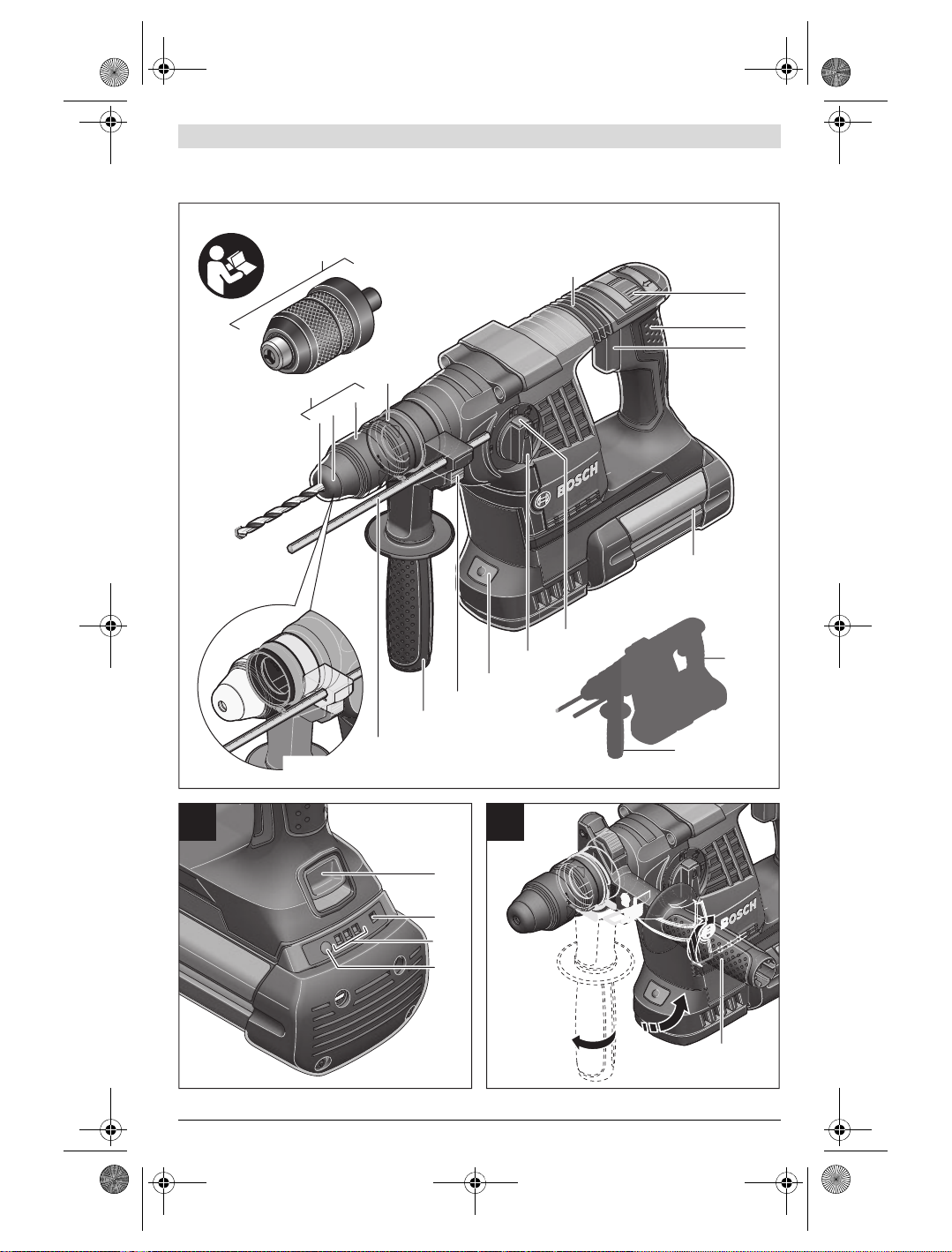
Abgebildete Komponenten
Die Nummerierung der abgebildeten Komponenten bezieht
sich auf die Darstellung des Elektrowerkzeuges auf der Grafikseite.
1 Schnellspann-Wechselbohrfutter (GBH 36 VF-LI Plus)
2 SDS-plus-Wechselbohrfutter (GBH 36 VF-LI Plus)
3 Werkzeugaufnahme SDS-plus
4 Staubschutzkappe
5 Verriegelungshülse
6 Wechselbohrfutter-Verriegelungsring
(GBH 36 VF-LI Plus)
7 Vibrationsdämpfung
8 Drehrichtungsumschalter
9 Handgriff (isolierte Grifffläche)
10 Ein-/Ausschalter
11 Akku *
12 Entriegelungstaste für Schlag-/Drehstopp-Schalter
13 Schlag-/Drehstopp-Schalter
14 Arbeitslicht
15 Taste für Tiefenanschlageinstellung
16 Zusatzgriff (isolierte Grifffläche)
17 Tiefenanschlag
18 Akku-Entriegelungstaste
19 Anzeige Temperaturüberwachung
20 Akku-Ladezustandsanzeige
21 Taste für Ladezustandsanzeige
22 Sicherungsschraube für Zahnkranzbohrfutter
(GBH 36 V-LI Plus) *
23 Zahnkranzbohrfutter (GBH 36 V-LI Plus) *
24 SDS-plus-Aufnahmeschaft für Bohrfutter
(GBH 36 V-LI Plus) *
25 Bohrfutteraufnahme (GBH 36 VF-LI Plus)
26 Kennrillen
27 Bohrfutterschlüssel (GBH 36 V-LI Plus)
28 Vordere Hülse des Schnellspann-Wechselbohrfutters
(GBH 36 VF-LI Plus)
29 Haltering des Schnellspann-Wechselbohrfutters
(GBH 36 VF-LI Plus)
30 EPC-Schalter (Electronic Precision Control)
31 Universalhalter mit SDS-plus-Aufnahmeschaft *
*Abgebildetes oder beschriebenes Zubehör gehört nicht zum
Standard-Lieferumfang. Das vollständige Zubehör finden Sie in
unserem Zubehörprogramm.
Technische Daten
Bohrhammer GBH 36 V-LI Plus GBH 36 VF-LI Plus
Sachnummer
Drehzahlsteuerung
Drehstopp
Rechts-/Linkslauf
Wechselbohrfutter
Nennspannung
Nennaufnahmeleistung
Schlagzahl
Einzelschlagstärke entsprechend EPTA-Procedure 05/2009
Nenndrehzahl
–Rechtslauf
–Linkslauf
V= 36 36
W600 600
-1
min
J3,2 3,2
-1
min
-1
min
Werkzeugaufnahme
Durchmesser Spindelhals
mm 50 50
Bohrdurchmesser max.:
–Beton
– Mauerwerk (mit Hohlbohrkrone)
–Stahl
–Holz
1) abhängig vom verwendeten Akku
2) eingeschränkte Leistung bei Temperaturen <0 ° C
Technische Daten ermittelt mit Akku aus Lieferumfang.
1 609 92A 2CS | (29.9.16) Bosch Power Tools
mm
mm
mm
mm
3 611 J06 0.. 3 611 J07 0..
–
0–4200 0–4200
0–940
0–930
0–940
0–930
SDS-plus SDS-plus
28
82
13
30
28
82
13
30
OBJ_BUCH-283-013.book Page 9 Thursday, September 29, 2016 8:34 AM
Deutsch | 9
Bohrhammer GBH 36 V-LI Plus GBH 36 VF-LI Plus
Gewicht entsprechend EPTA-Procedure 01:2014
kg 4,0/4,5
1)
4,1/4,6
erlaubte Umgebungstemperatur
–beim Laden
–beim Betrieb
2)
und bei Lagerung
empfohlene Akkus
empfohlene Ladegeräte
1) abhängig vom verwendeten Akku
2) eingeschränkte Leistung bei Temperaturen <0 ° C
Technische Daten ermittelt mit Akku aus Lieferumfang.
Geräusch-/Vibrationsinformation
Geräuschemissionswerte ermittelt entsprechend
EN 60745-2-6.
Der A-bewertete Geräuschpegel des Elektrowerkzeugs beträgt typischerweise: Schalldruckpegel 90 dB(A); Schallleistungspegel 101 dB(A). Unsicherheit K= 3 dB.
Gehörschutz tragen!
Schwingungsgesamtwerte a
gen) und Unsicherheit K ermittelt entsprechend
EN 60745-2-6:
Hammerbohren in Beton: a
Meißeln: ah= 9,5 m/s2, K= 1,5 m/s
Bohren in Metall: ah<2,5m/s2, K=1,5 m/s
Schrauben: ah<2,5m/s2, K= 1,5 m/s
Der in diesen Anweisungen angegebene Schwingungspegel
ist entsprechend einem in EN 60745 genormten Messverfahren gemessen worden und kann für den Vergleich von
Elektrowerkzeugen miteinander verwendet werden. Er eignet sich auch für eine vorläufige Einschätzung der Schwingungsbelastung.
Der angegebene Schwingungspegel repräsentiert die hauptsächlichen Anwendungen des Elektrowerkzeugs. Wenn
allerdings das Elektrowerkzeug für andere Anwendungen,
mit unterschiedlichen Zubehören, mit abweichenden Einsatzwerkzeugen oder ungenügender Wartung eingesetzt
wird, kann der Schwingungspegel abweichen. Dies kann die
(Vektorsumme dreier Richtun-
h
=14,5 m/s2, K= 1,5 m/s
h
2
2
2
2
°C
°C
Montage
Akku laden (siehe Bild A)
Benutzen Sie nur die auf der Zubehörseite aufgeführten
Ladegeräte. Nur diese Ladegeräte sind auf den bei Ihrem
Elektrowerkzeug verwendeten Li-Ionen-Akku abgestimmt.
Hinweis: Der Akku wird teilgeladen ausgeliefert. Um die volle
Leistung des Akkus zu gewährleisten, laden Sie vor dem ersten Einsatz den Akku vollständig im Ladegerät auf.
Der Li-Ionen-Akku kann jederzeit aufgeladen werden, ohne
die Lebensdauer zu verkürzen. Eine Unterbrechung des Ladevorganges schädigt den Akku nicht.
Der Li-Ionen-Akku ist durch die „Electronic Cell Protection
(ECP)“ gegen Tiefentladung geschützt. Bei entladenem Akku
wird das Elektrowerkzeug durch eine Schutzschaltung abgeschaltet: Das Einsatzwerkzeug bewegt sich nicht mehr.
Drücken Sie nach dem automatischen Abschalten des
Elektrowerkzeuges nicht weiter auf den Ein-/Ausschalter. Der Akku kann beschädigt werden.
Akku entnehmen
Der Akku 11 verfügt über zwei Verriegelungsstufen, die ver-
hindern sollen, dass der Akku beim unbeabsichtigten Drücken der Akku-Entriegelungstaste 18 herausfällt. Solange der
Akku im Elektrowerkzeug eingesetzt ist, wird er durch eine
Feder in Position gehalten.
0... +45
–20...+50
0...+45
–20...+50
GBA 36V ... GBA 36V ...
AL36..
GAL 36..
AL36..
GAL 36..
Schwingungsbelastung über den gesamten Arbeitszeitraum
deutlich erhöhen.
Für eine genaue Abschätzung der Schwingungsbelastung
sollten auch die Zeiten berücksichtigt werden, in denen das
Gerät abgeschaltet ist oder zwar läuft, aber nicht tatsächlich
im Ei ns at z i st . D ie s k an n d ie Sc hw in gun gs be la st un g ü be r d en
gesamten Arbeitszeitraum deutlich reduzieren.
Legen Sie zusätzliche Sicherheitsmaßnahmen zum Schutz
des Bedieners vor der Wirkung von Schwingungen fest wie
zum Beispiel: Wartung von Elektrowerkzeug und Einsatzwerkzeugen, Warmhalten der Hände, Organisation der
Arbeitsabläufe.
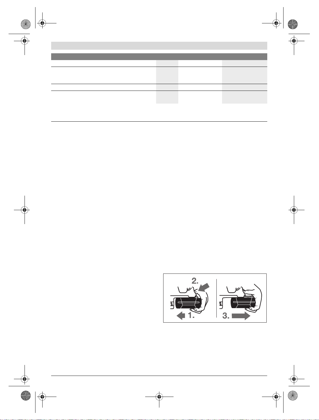
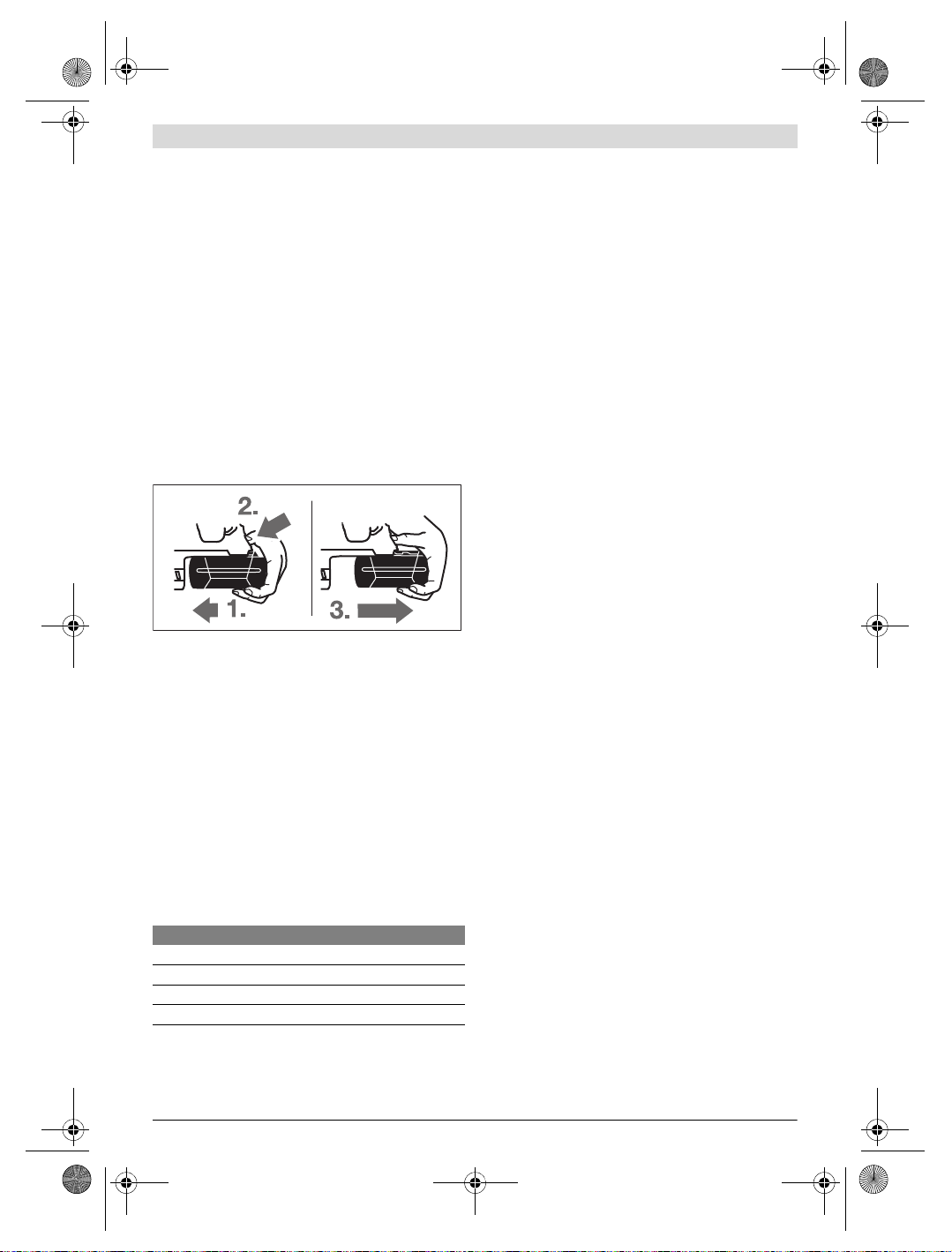
Zum Entnehmen des Akkus 11:
– Drücken Sie den Akku gegen den Fuß des Elektrowerkzeu-
ges (1.) und gleichzeitig auf die Entriegelungstaste 18 (2.).
–Ziehen Sie den Akku vom Elektrowerkzeug ab, bis ein roter
Streifen sichtbar wird (3.).
–Drücken Sie nochmals die Entriegelungstaste 18 und
ziehen Sie den Akku vollständig heraus.
1)
Bosch Power Tools 1 609 92A 2CS | (29.9.16)
OBJ_BUCH-283-013.book Page 10 Thursday, September 29, 2016 8:34 AM
10 | Deutsch
Akku-Ladezustandsanzeige
Die drei grünen LEDs der Akku-Ladezustandsanzeige 20 zeigen den Ladezustand des Akkus 11 an. Aus Sicherheitsgründen ist die Abfrage des Ladezustands nur bei Stillstand des
Elektrowerkzeuges möglich.
– Drücken Sie die Taste 21, um den Ladezustand anzuzeigen
(auch bei abgenommenem Akku möglich). Nach ca.
5 Sekunden erlischt die Ladezustandsanzeige selbsttätig.
LED Kapazität
Dauerlicht 3 x Grün 2/3
Dauerlicht 2 x Grün 1/3
Dauerlicht 1 x Grün <1/3
Blinklicht 1 x Grün Reserve
Leuchtet nach dem Drücken der Taste 21 keine LED, ist der
Akku defekt und muss ausgetauscht werden.
Während des Ladevorganges leuchten die drei grünen LEDs
nacheinander auf und erlöschen kurzzeitig. Der Akku ist vollständig geladen, wenn die drei grünen LEDs dauerhaft leuchten. Etwa 5 Minuten nachdem der Akku vollständig geladen
wurde, erlöschen die drei grünen LEDs wieder.
Zusatzgriff
Verwenden Sie Ihr Elektrowerkzeug nur mit dem
Zusatzgriff 16.
Zusatzgriff schwenken (siehe Bild B)
Sie können den Zusatzgriff 16 beliebig schwenken, um eine
sichere und ermüdungsarme Arbeitshaltung zu erreichen.
– Drehen Sie das untere Griffstück des Zusatzgriffs 16 ent-
gegen dem Uhrzeigersinn und schwenken Sie den Zusatzgriff 16 in die gewünschte Position. Danach drehen Sie das
untere Griffstück des Zusatzgriffs 16 im Uhrzeigersinn
wieder fest.
Achten Sie darauf, dass das Spannband des Zusatzgriffs in
der dafür vorgesehenen Nut am Gehäuse liegt.
Bohrfutter und Werkzeuge auswählen
Zum Hammerbohren und Meißeln benötigen Sie SDS-plusWerkzeuge, die in das SDS-plus-Bohrfutter eingesetzt werden.
Zum Bohren ohne Schlag in Holz, Metall, Keramik und Kunststoff sowie zum Schrauben werden Werkzeuge ohne SDSplus (z.B. Bohrer mit zylindrischem Schaft) verwendet. Für
diese Werkzeuge benötigen Sie ein Schnellspannbohrfutter
bzw. Zahnkranzbohrfutter.
Zahnkranzbohrfutter einsetzen/entnehmen
(GBH 36 V-LI Plus)
Um mit Werkzeugen ohne SDS-plus (z.B. Bohrer mit zylindrischem Schaft) arbeiten zu können, müssen Sie ein geeignetes Bohrfutter montieren (Zahnkranz- oder Schnellspannbohrfutter, Zubehör).
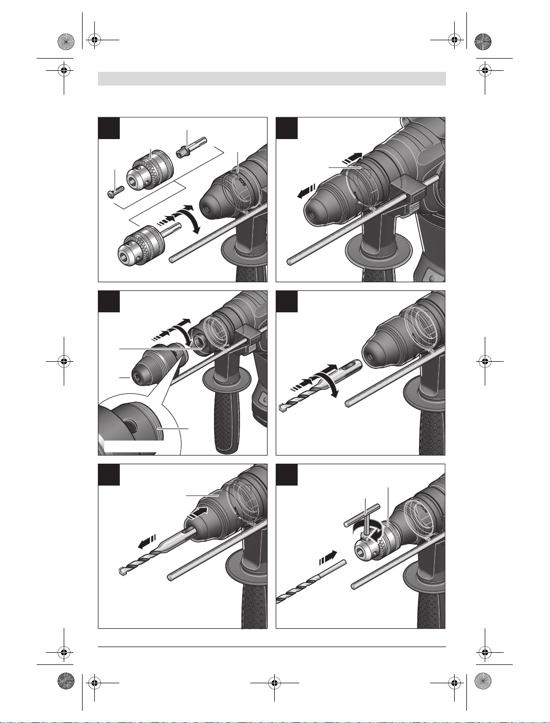
Zahnkranzbohrfutter montieren (siehe Bild C)
– Schrauben Sie den SDS-plus-Aufnahmeschaft 24 in ein
Zahnkranzbohrfutter 23. Sichern Sie das Zahnkranzbohrfutter 23 mit der Sicherungsschraube 22. Beachten Sie,
dass die Sicherungsschraube ein Linksgewinde hat.
Zahnkranzbohrfutter einsetzen (siehe Bild C)
– Reinigen Sie das Einsteckende des Aufnahmeschaftes und
fetten Sie es leicht ein.
– Setzen Sie das Zahnkranzbohrfutter mit dem Aufnahme-
schaft drehend in die Werkzeugaufnahme ein, bis es
selbsttätig verriegelt wird.
– Prüfen Sie die Verriegelung durch Ziehen am Zahnkranz-
bohrfutter.
Zahnkranzbohrfutter entnehmen
– Schieben Sie die Verriegelungshülse 5 nach hinten und
nehmen Sie das Zahnkranzbohrfutter 23 ab.
Wechselbohrfutter entnehmen/einsetzen
(GBH 36 VF-LI Plus)
Das SDS-plus-Wechselbohrfutter 2 kann leicht gegen das mitgelieferte Schnellspann-Wechselbohrfutter 1 ausgetauscht
werden.
Wechselbohrfutter entnehmen (siehe Bild D)
–Ziehen Sie den Wechselbohrfutter-Verriegelungsring 6
nach hinten, halten Sie ihn in dieser Position fest und
ziehen Sie das SDS-plus-Wechselbohrfutter 2 bzw. das
Schnellspann-Wechselbohrfutter 1 nach vorn ab.
– Schützen Sie das Wechselbohrfutter nach dem Abnehmen
vor Verschmutzung.
Wechselbohrfutter einsetzen (siehe Bild E)
Verwenden Sie nur modellspezifische Originalausstat-
tung und achten Sie dabei auf die Anzahl der Kennrillen
26. Es sind nur Wechselbohrfutter mit zwei oder drei
Kennrillen zulässig. Wird ein für dieses Elektrowerkzeug
nicht geeignetes Wechselbohrfutter verwendet, kann das
Einsatzwerkzeug während des Betriebs herausfallen.
– Reinigen Sie das Wechselbohrfutter vor dem Einsetzen
und fetten Sie das Einsteckende leicht ein.
– Umgreifen Sie das SDS-plus-Wechselbohrfutter 2 bzw.
das Schnellspann-Wechselbohrfutter 1 mit der ganzen
Hand. Schieben Sie das Wechselbohrfutter drehend auf
die Bohrfutteraufnahme 25, bis Sie ein deutliches Einrastgeräusch hören.
– Das Wechselbohrfutter verriegelt sich selbsttätig. Über-
prüfen Sie die Verriegelung durch Ziehen am Wechselbohrfutter.
Werkzeugwechsel
Die Staubschutzkappe 4 verhindert weitgehend das Eindringen von Bohrstaub in die Werkzeugaufnahme während des
Betriebes. Achten Sie beim Einsetzen des Werkzeuges darauf, dass die Staubschutzkappe 4 nicht beschädigt wird.
Eine beschädigte Staubschutzkappe ist sofort zu erset-
zen. Es wird empfohlen, dies von einem Kundendienst
vornehmen zu lassen.
1 609 92A 2CS | (29.9.16) Bosch Power Tools

OBJ_BUCH-283-013.book Page 11 Thursday, September 29, 2016 8:34 AM
Deutsch | 11
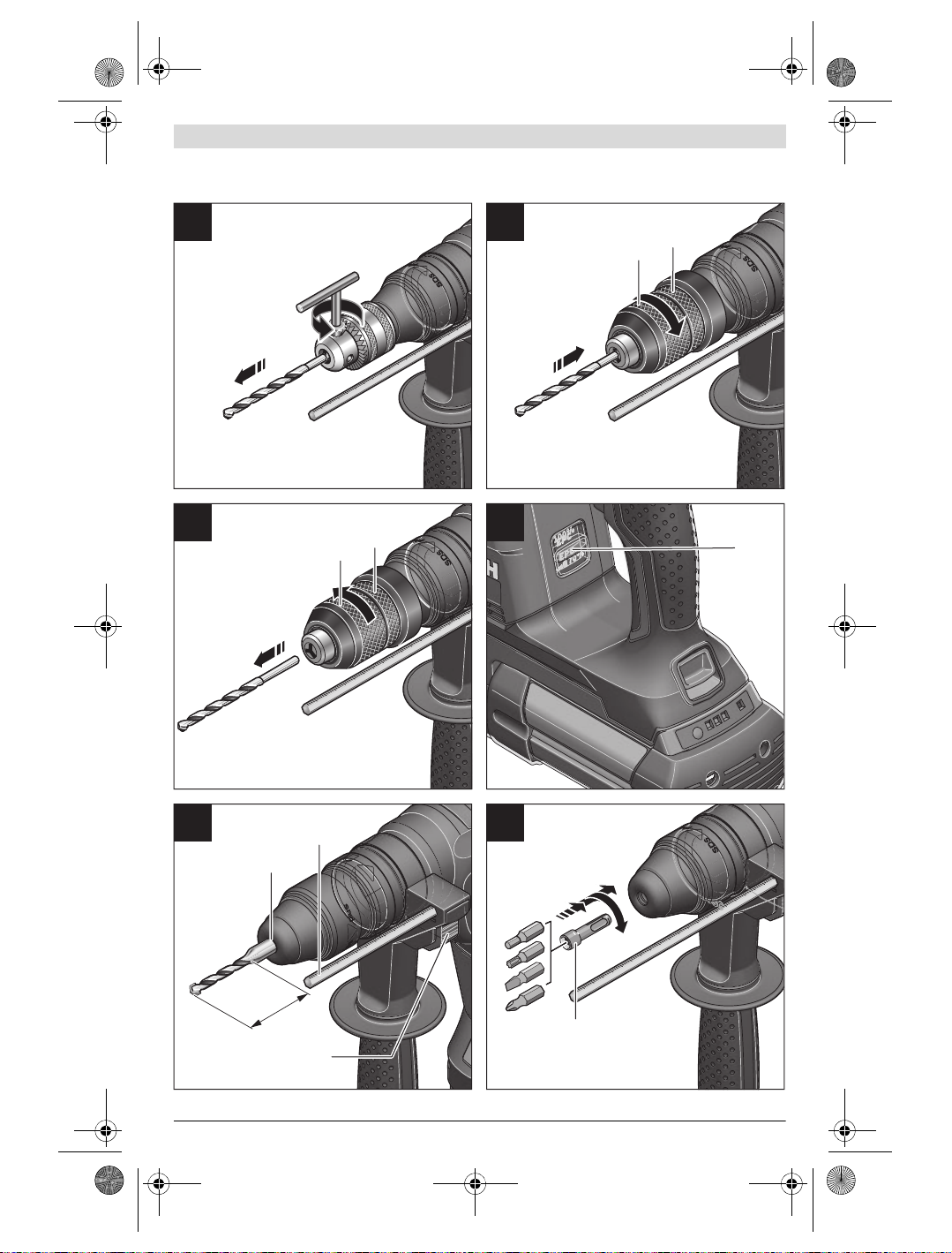
Werkzeugwechsel (SDS-plus)
SDS-plus-Einsatzwerkzeug einsetzen (siehe Bild F)
Mit dem SDS-plus-Bohrfutter können Sie das Einsatzwerkzeug einfach und bequem ohne Verwendung zusätzlicher
Werkzeuge wechseln.
– GBH 36 VF-LI Plus: Setzen Sie das SDS-plus-Wechsel-
bohrfutter 2 ein.
– Reinigen Sie das Einsteckende des Einsatzwerkzeuges und
fetten Sie es leicht ein.
– Setzen Sie das Einsatzwerkzeug drehend in die Werkzeug-
aufnahme ein, bis es selbsttätig verriegelt wird.
– Überprüfen Sie die Verriegelung durch Ziehen am Werk-
zeug.
Das SDS-plus-Einsatzwerkzeug ist systembedingt frei beweglich. Dadurch entsteht beim Leerlauf eine Rundlaufabweichung. Dies hat keine Auswirkungen auf die Genauigkeit des
Bohrlochs, da sich der Bohrer beim Bohren selbst zentriert.
SDS-plus-Einsatzwerkzeug entnehmen (siehe Bild G)
– Schieben Sie die Verriegelungshülse 5 nach hinten und
entnehmen Sie das Einsatzwerkzeug.
Werkzeugwechsel (ohne SDS-plus)
(GBH 36 V-LI Plus)
Einsatzwerkzeug einsetzen (siehe Bild H)
Hinweis: Verwenden Sie Werkzeuge ohne SDS-plus nicht
zum Hammerbohren oder Meißeln! Werkzeuge ohne SDSplus und ihr Bohrfutter werden beim Hammerbohren und
Meißeln beschädigt.
– Setzen Sie ein Zahnkranzbohrfutter 23 ein (siehe „Zahn-
kranzbohrfutter einsetzen/entnehmen“, Seite 10).
– Öffnen Sie das Zahnkranzbohrfutter 23 durch Drehen, bis
das Werkzeug eingesetzt werden kann. Setzen Sie das
Werkzeug ein.
– Stecken Sie den Bohrfutterschlüssel in die entsprechen-
den Bohrungen des Zahnkranzbohrfutters 23 und spannen Sie das Werkzeug gleichmäßig fest.
– Drehen Sie den Schlag-/Drehstopp-Schalter 13 in die
Position „Bohren“.
Einsatzwerkzeug entnehmen (siehe Bild I)
– Drehen Sie die Hülse des Zahnkranzbohrfutters 23 mithil-
fe des Bohrfutterschlüssels entgegen dem Uhrzeigersinn,
bis das Einsatzwerkzeug entnommen werden kann.
Werkzeugwechsel (ohne SDS-plus)
und drehen Sie die vordere Hülse 28 kräftig in Pfeilrichtung, bis deutliche Ratschengeräusche zu hören sind.
– Prüfen Sie den festen Sitz durch Ziehen am Werkzeug.
Hinweis: Wurde die Werkzeugaufnahme bis zum Anschlag ge-
öffnet, kann beim Zudrehen der Werkzeugaufnahme das Ratschengeräusch zu hören sein und die Werkzeugaufnahme
schließt sich nicht.
Drehen Sie in diesem Fall die vordere Hülse 28 einmal entgegen der Pfeilrichtung. Danach kann die Werkzeugaufnahme
geschlossen werden.
– Drehen Sie den Schlag-/Drehstopp-Schalter 13 in die
Position „Bohren“.
Einsatzwerkzeug entnehmen (siehe Bild K)
– Halten Sie den Haltering 29 des Schnellspann-Wechsel-
bohrfutters fest. Öffnen Sie die Werkzeugaufnahme durch
Drehen der vorderen Hülse 28 in Pfeilrichtung, bis das
Werkzeug entnommen werden kann.
Staubabsaugung mit GDE 16 Plus (Zubehör)
Stäube von Materialien wie bleihaltigem Anstrich, einigen
Holzarten, Mineralien und Metall können gesundheitsschädlich sein. Berühren oder Einatmen der Stäube können allergische Reaktionen und/oder Atemwegserkrankungen des Benutzers oder in der Nähe befindlicher Personen hervorrufen.
Bestimmte Stäube wie Eichen- oder Buchenstaub gelten als
krebserzeugend, besonders in Verbindung mit Zusatzstoffen zur Holzbehandlung (Chromat, Holzschutzmittel). Asbesthaltiges Material darf nur von Fachleuten bearbeitet
werden.
– Benutzen Sie möglichst eine für das Material geeignete
Staubabsaugung.
– Sorgen Sie für gute Belüftung des Arbeitsplatzes.
–Es wird empfohlen, eine Atemschutzmaske mit Filter-
klasse P2 zu tragen.
Beachten Sie in Ihrem Land gültige Vorschriften für die zu
bearbeitenden Materialien.
Vermeiden Sie Staubansammlungen am Arbeitsplatz.
Stäube können sich leicht entzünden.
Für die Staubabsaugung wird ein GDE 16 Plus (Zubehör)
benötigt.
Der Staubsauger muss für den zu bearbeitenden Werkstoff
geeignet sein.
Verwenden Sie beim Absaugen von besonders gesundheitsgefährdenden, krebserzeugenden oder trockenen Stäuben
einen Spezialsauger.
(GBH 36 VF-LI Plus)
Einsatzwerkzeug einsetzen (siehe Bild J)
Hinweis: Verwenden Sie Werkzeuge ohne SDS-plus nicht
zum Hammerbohren oder Meißeln! Werkzeuge ohne SDSplus und ihr Bohrfutter werden beim Hammerbohren und Meißeln beschädigt.
– Setzen Sie das Schnellspann-Wechselbohrfutter 1 ein.
– Halten Sie den Haltering 29 des Schnellspann-Wechsel-
bohrfutters fest. Öffnen Sie die Werkzeugaufnahme durch
Drehen der vorderen Hülse 28 so weit, bis das Werkzeug
eingesetzt werden kann. Halten Sie den Haltering 29 fest
Bosch Power Tools 1 609 92A 2CS | (29.9.16)
Betrieb
Inbetriebnahme
Akku einsetzen
– Stellen Sie den Drehrichtungsumschalter 8 auf Mittelstel-
lung, um das Elektrowerkzeug vor unbeabsichtigtem Einschalten zu schützen.
– Schieben Sie den geladenen Akku 11 von hinten in den
Fuß des Elektrowerkzeugs hinein. Drücken Sie den Akku
vollständig in den Fuß, bis der rote Streifen nicht mehr zu
sehen und der Akku sicher verriegelt ist.
OBJ_BUCH-283-013.book Page 12 Thursday, September 29, 2016 8:34 AM
12 | Deutsch
Betriebsart einstellen
Mit dem Schlag-/Drehstopp-Schalter 13 wählen Sie die Betriebsart des Elektrowerkzeugs.
Hinweis: Ändern Sie die Betriebsart nur bei ausgeschaltetem
Elektrowerkzeug! Das Elektrowerkzeug kann sonst beschädigt werden.
– Drücken Sie zum Wechsel der Betriebsart die Entriege-
lungstaste 12 und drehen Sie den Schlag-/DrehstoppSchalter 13 in die gewünschte Position, bis er hörbar einrastet.
Leichter Druck auf den Ein-/Ausschalter 10 bewirkt eine niedrige Drehzahl/Schlagzahl. Mit zunehmendem Druck erhöht
sich die Drehzahl/Schlagzahl.
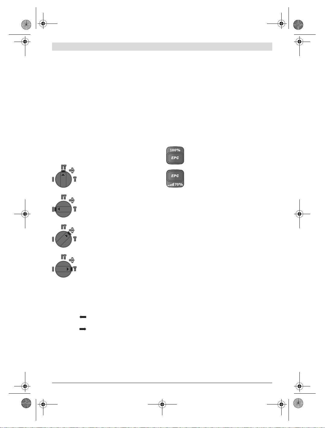
Electronic Precision Control (EPC) (siehe Bild L)
EPC unterstützt Sie bei Arbeiten mit Schlag in empfindliche
Materialien durch langsames Hochlaufen und eine reduzierte
Arbeitsdrehzahl.
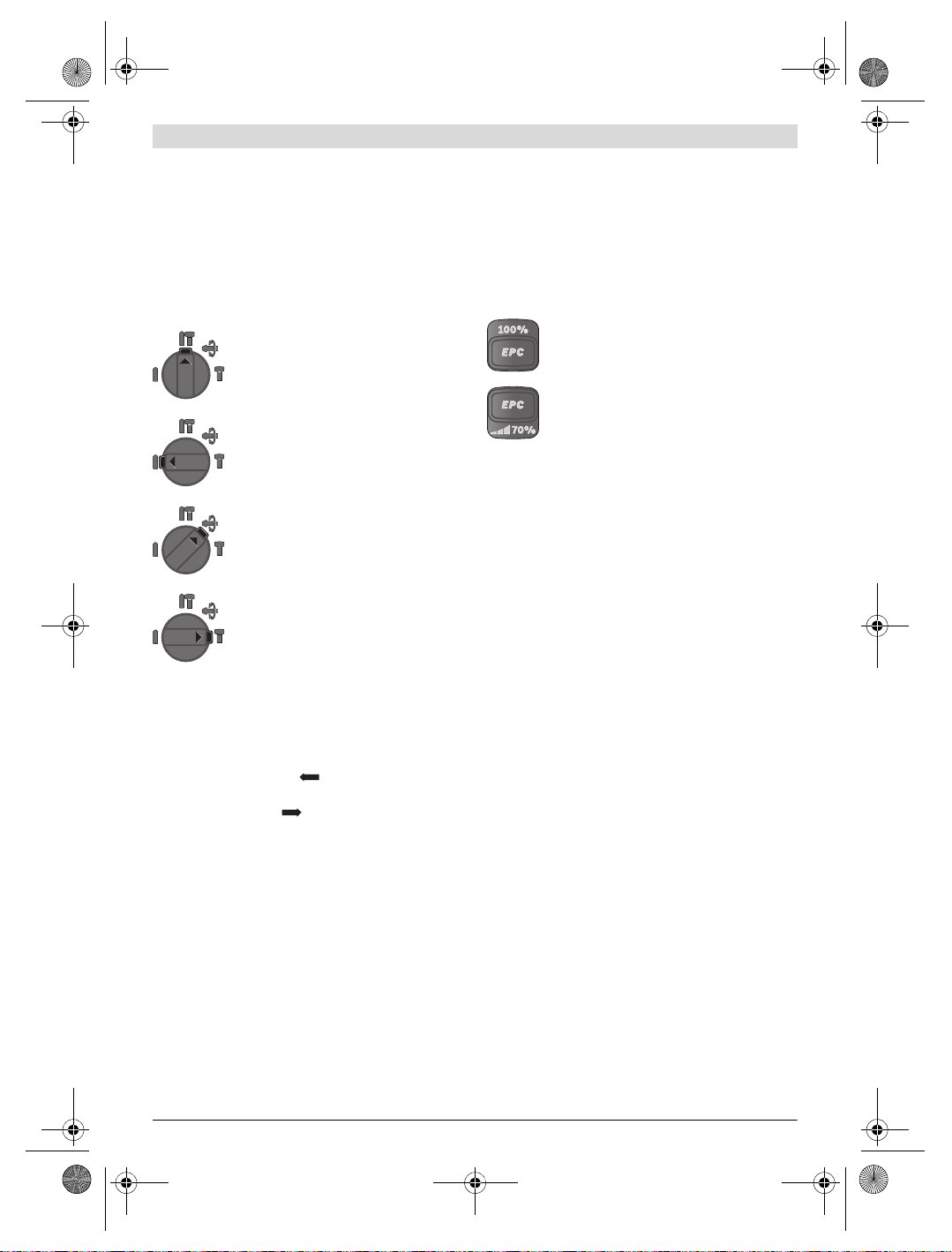
– Schieben Sie den EPC-Schalter 30 in die gewünschte
Position.
Position zum Hammerbohren in Beton oder
Stein
Position zum Bohren ohne Schlag in Holz,
Metall, Keramik und Kunststoff sowie zum
Schrauben
Position Vario-Lock zum Verstellen der
Meißelposition
In dieser Position rastet der Schlag-/Drehstopp-Schalter 13 nicht ein.
Position zum Meißeln
Drehrichtung einstellen
Mit dem Drehrichtungsumschalter 8 können Sie die Drehrichtung des Elektrowerkzeuges ändern. Bei gedrücktem Ein-/
Ausschalter 10 ist dies jedoch nicht möglich.
Rechtslauf: Schieben Sie den Drehrichtungsumschalter 8
bis zum Anschlag in Position .
Linkslauf: Schieben Sie den Drehrichtungsumschalter 8 bis
zum Anschlag in Position .
Stellen Sie die Drehrichtung zum Hammerbohren, Bohren
und Meißeln immer auf Rechtslauf.
Ein-/Ausschalten
Um Energie zu sparen, schalten Sie das Elektrowerkzeug nur
ein, wenn Sie es benutzen.
–Zum Einschalten des Elektrowerkzeugs drücken Sie den
Ein-/Ausschalter 10.
Beim erstmaligen Einschalten des Elektrowerkzeugs kann es
zu einer Anlaufverzögerung kommen, da sich die Elektronik
des Elektrowerkzeugs erst konfigurieren muss.
–Zum Ausschalten lassen Sie den Ein-/Ausschalter 10 los.
Drehzahl/Schlagzahl einstellen
Sie können die Drehzahl/Schlagzahl des eingeschalteten
Elektrowerkzeugs stufenlos regulieren, je nachdem, wie weit
Sie den Ein-/Ausschalter 10 eindrücken.
Position für maximale Arbeitsdrehzahl
Position für langsames Hochlaufen und reduzierte Arbeitsdrehzahl
Überlastkupplung
Klemmt oder hakt das Einsatzwerkzeug, wird der An-
trieb zur Bohrspindel unterbrochen. Halten Sie, wegen
der dabei auftretenden Kräfte, das Elektrowerkzeug
immer mit beiden Händen gut fest und nehmen Sie
einen festen Stand ein.
Schalten Sie das Elektrowerkzeug aus und lösen Sie
das Einsatzwerkzeug, wenn das Elektrowerkzeug blockiert. Beim Einschalten mit einem blockierten Bohrwerkzeug entstehen hohe Reaktionsmomente.
Schnellabschaltung (ERC)
Die Schnellabschaltung bietet eine bessere Kontrolle über
das Elektrowerkzeug. Bei plötzlicher und unvorhersehbarer
Rotation des Elektrowerkzeugs um die Bohrerachse schaltet
das Elektrowerkzeug ab.
Die Schnellabschaltung wird durch ein Blinken des Arbeitslichtes 14 am Elektrowerkzeug angezeigt.
ur Wiederinbetriebnahme lassen Sie den Ein-/Aus-
–Z
sch
alter los und betätigen Sie ihn erneut.
Die Schnellabschaltung kann nur auslösen, wenn das
Elektrowerkzeug bei maximaler Arbeitsdrehzahl läuft
und sich frei um die Bohrerachse drehen kann. Wählen
Sie dazu eine geeignete Arbeitsposition. Andernfalls ist die
Schnellabschaltung nicht gewährleistet.
Anzeige für Temperaturüberwachung
Die rote LED der Anzeige für Temperaturüberwachung 19 signalisiert, dass der Akku oder die Elektronik des Elektrowerkzeuges (bei eingesetztem Akku) nicht im optimalen Temperaturbereich sind. In diesem Fall arbeitet das Elektrowerkzeug
nicht oder nicht mit voller Leistung.
Temperaturüberwachung des Akkus:
–Die rote LED 19 leuchtet beim Einsetzen des Akkus in das
Ladegerät dauerhaft: Der Akku ist außerhalb des Ladetemperaturbereiches von 0 ° C bis 45 ° C und kann nicht geladen werden.
–Die rote LED 19 blinkt beim Drücken der Taste 21 oder des
Ein-/Ausschalters 10 (bei eingesetztem Akku): Der Akku ist
außerhalb des zulässigen Betriebstemperaturbereiches.
1 609 92A 2CS | (29.9.16) Bosch Power Tools

OBJ_BUCH-283-013.book Page 13 Thursday, September 29, 2016 8:34 AM
– Bei einer Akku-Temperatur von über 70 ° C schaltet das
Elektrowerkzeug ab, bis der Akku wieder im optimalen
Temperaturbereich ist.
Temperaturüberwachung der Elektronik des Elektrowerkzeuges:
– Die rote LED 19 leuchtet beim Drücken des Ein-/Ausschal-
ters 10 dauerhaft: Die Temperatur der Elektronik des Elektrowerkzeuges beträgt weniger als 5 ° C oder mehr als
75 ° C.
– Bei einer Temperatur über 90 ° C schaltet die Elektronik
des Elektrowerkzeuges ab, bis diese wieder im zulässigen
Betriebstemperaturbereich ist.
Arbeitshinweise
Bohrtiefe einstellen (siehe Bild M)
Mit dem Tiefenanschlag 17 kann die gewünschte Bohrtiefe X
festgelegt werden.
– Drücken Sie die Taste für die Tiefenanschlageinstellung 15
und setzen Sie den Tiefenanschlag in den Zusatzgriff 16
ein.
Die Riffelung am Tiefenanschlag 17 muss nach unten
zeigen.
– Schieben Sie das SDS-plus-Einsatzwerkzeug bis zum An-
schlag in die Werkzeugaufnahme SDS-plus 3. Die Beweg-
lichkeit des SDS-plus-Werkzeugs kann sonst zu einer falschen Einstellung der Bohrtiefe führen.
– Ziehen Sie den Tiefenanschlag so weit heraus, dass der
Abstand zwischen der Spitze des Bohrers und der Spitze
des Tiefenanschlags der gewünschten Bohrtiefe X ent-
spricht.
Verändern der Meißelstellung (Vario-Lock)
Sie können den Meißel in 36 Stellungen arretieren. Dadurch
können Sie die jeweils optimale Arbeitsposition einnehmen.
– Setzen Sie den Meißel in die Werkzeugaufnahme ein.
– Drehen Sie den Schlag-/Drehstopp-Schalter 13 in die
Position „Vario-Lock“ (siehe „Betriebsart einstellen“,
Seite 12).
– Drehen Sie das Einsatzwerkzeug in die gewünschte
Meißelstellung.
– Drehen Sie den Schlag-/Drehstopp-Schalter 13 in die
Position „Meißeln“. Die Werkzeugaufnahme ist damit arretiert.
– Stellen Sie die Drehrichtung zum Meißeln auf Rechtslauf.
Schrauberbits einsetzen (siehe Bild N)
Setzen Sie das Elektrowerkzeug nur ausgeschaltet auf
die Mutter/Schraube auf. Sich drehende Einsatzwerk-
zeuge können abrutschen.
Zur Verwendung von Schrauberbits benötigen Sie einen Universalhalter 31 mit SDS-plus-Aufnahmeschaft (Zubehör).
– Reinigen Sie das Einsteckende des Aufnahmeschaftes und
fetten Sie es leicht ein.
– Setzen Sie den Universalhalter drehend in die Werkzeug-
aufnahme ein, bis er selbsttätig verriegelt wird.
– Prüfen Sie die Verriegelung durch Ziehen am Universal-
halter.
– Setzen Sie einen Schrauberbit in den Universalhalter. Ver-
wenden Sie nur zum Schraubenkopf passende Schrauberbits.
– Zum Entnehmen des Universalhalters schieben Sie die
Verriegelungshülse 5 nach hinten und entnehmen den Universalhalter 31 aus der Werkzeugaufnahme.
Vibrationsdämpfung
Die integrierte Vibrationsdämpfung reduziert auftretende
Vibrationen.
Der Softgriff erhöht die Abrutschsicherheit und sorgt dadurch für bessere Griffigkeit und Handlichkeit des Elektrowerkzeuges.
Hinweise für den optimalen Umgang mit dem Akku
Schützen Sie den Akku vor Feuchtigkeit und Wasser.
Lagern Sie den Akku nur im Temperaturbereich von –20 ° C
bis 50 °C. Lassen Sie den Akku z. B. im Sommer nicht im Auto
liegen.
Reinigen Sie gelegentlich die Lüftungsschlitze des Akkus mit
einem weichen, sauberen und trockenen Pinsel.
Eine wesentlich verkürzte Betriebszeit nach der Aufladung
zeigt an, dass der Akku verbraucht ist und ersetzt werden
muss.
Beachten Sie die Hinweise zur Entsorgung.
Wartung und Service
Wartung und Reinigung
Nehmen Sie den Akku vor allen Arbeiten am Elektro-
werkzeug (z.B. Wartung, Werkzeugwechsel etc.) sowie bei dessen Transport und Aufbewahrung aus dem
Elektrowerkzeug. Bei unbeabsichtigtem Betätigen des
Ein-/Ausschalters besteht Verletzungsgefahr.
Halten Sie das Elektrowerkzeug und die Lüftungs-
schlitze sauber, um gut und sicher zu arbeiten.
Eine beschädigte Staubschutzkappe ist sofort zu erset-
zen. Es wird empfohlen, dies von einem Kundendienst
vornehmen zu lassen.
– Säubern Sie die Werkzeugaufnahme 3 nach jedem
Gebrauch.
Kundendienst und Anwendungsberatung
Der Kundendienst beantwortet Ihre Fragen zu Reparatur und
Wartung Ihres Produkts sowie zu Ersatzteilen. Explosionszeichnungen und Informationen zu Ersatzteilen finden Sie
auch unter:
www.bosch-pt.com
Das Bosch-Anwendungsberatungs-Team hilft Ihnen gerne bei
Fragen zu unseren Produkten und deren Zubehör.
www.powertool-portal.de, das Internetportal für Handwerker und Heimwerker.
Deutsch | 13
Bosch Power Tools 1 609 92A 2CS | (29.9.16)
WARNING
OBJ_BUCH-283-013.book Page 14 Thursday, September 29, 2016 8:34 AM
14 | English
Geben Sie bei allen Rückfragen und Ersatzteilbestellungen
bitte unbedingt die 10-stellige Sachnummer laut Typenschild
des Produkts an.
Deutschland
Robert Bosch Power Tools GmbH
Servicezentrum Elektrowerkzeuge
Zur Luhne 2
37589 Kalefeld – Willershausen
Unter www.bosch-pt.com können Sie online Ersatzteile
bestellen oder Reparaturen anmelden.
Kundendienst: Tel.: (0711) 40040460
Fax: (0711) 40040461
E-Mail: Servicezentrum.Elektrowerkzeuge@de.bosch.com
Anwendungsberatung: Tel.: (0711) 40040460
Fax: (0711) 40040462
E-Mail: kundenberatung.ew@de.bosch.com
Österreich
Unter www.bosch-pt.at können Sie online Ersatzteile
bestellen.
Tel.: (01) 797222010
Fax: (01) 797222011
E-Mail: service.elektrowerkzeuge@at.bosch.com
Schweiz
Unter www.bosch-pt.com/ch/de können Sie online
Ersatzteile bestellen.
Tel.: (044) 8471511
Fax: (044) 8471551
E-Mail: Aftersales.Service@de.bosch.com
Luxemburg
Tel.: +32 2 588 0589
Fax: +32 2 588 0595
E-Mail: outillage.gereedschap@be.bosch.com
Transport
Die enthaltenen Li-Ionen-Akkus unterliegen den Anforderungen des Gefahrgutrechts. Die Akkus können durch den
Benutzer ohne weitere Auflagen auf der Straße transportiert
werden.
Beim Versand durch Dritte (z.B.: Lufttransport oder Spedition) sind besondere Anforderungen an Verpackung und
Kennzeichnung zu beachten. Hier muss bei der Vorbereitung
des Versandstückes ein Gefahrgut-Experte hinzugezogen
werden.
Versenden Sie Akkus nur, wenn das Gehäuse unbeschädigt
ist. Kleben Sie offene Kontakte ab und verpacken Sie den
Akku so, dass er sich nicht in der Verpackung bewegt.
Bitte beachten Sie auch eventuelle weiterführende nationale
Vorschriften.
Entsorgung
Elektrowerkzeuge, Akkus, Zubehör und Verpackungen sollen einer umweltgerechten Wiederverwertung
zugeführt werden.
Werfen Sie Elektrowerkzeuge und Akkus/Batterien nicht in
den Hausmüll!
Nur für EU-Länder:
Nicht mehr gebrauchsfähige Akkus/Batterien können direkt
abgegeben werden bei:
Deutschland
Recyclingzentrum Elektrowerkzeuge
Osteroder Landstraße 3
37589 Kalefeld
Schweiz
Batrec AG
3752 Wimmis BE
Akkus/Batterien:
Änderungen vorbehalten.
English
Safety Notes
General Power Tool Safety Warnings
instructions may result in electric shock, fire and/or serious
injury.
Save all warnings and instructions for future reference.
The term “power tool” in the warnings refers to your mainsoperated (corded) power tool or battery-operated (cordless)
power tool.
Work area safety
Keep work area clean and well lit. Cluttered or dark areas
invite accidents.
Do not operate power tools in explosive atmospheres,
such as in the presence of flammable liquids, gases or
dust. Power tools create sparks which may ignite the dust
or fumes.
Keep children and bystanders away while operating a
power tool. Distractions can cause you to lose control.
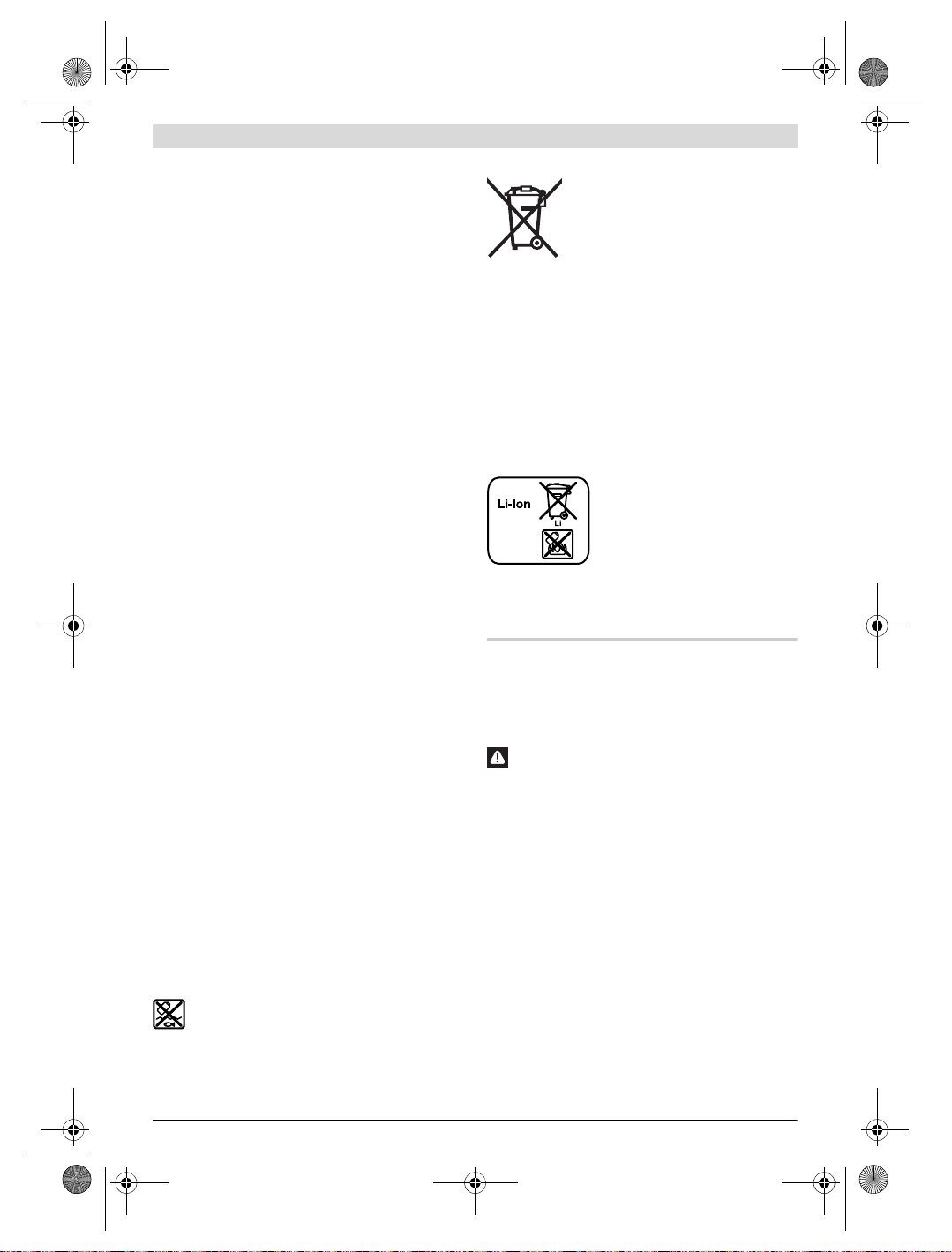
Gemäß der europäischen Richtlinie
2012/19/EU müssen nicht mehr gebrauchsfähige Elektrowerkzeuge und gemäß der
europäischen Richtlinie 2006/66/EG
müssen defekte oder verbrauchte Akkus/
Batterien getrennt gesammelt und einer
umweltgerechten Wiederverwendung
zugeführt werden.
Li-Ion:
Bitte beachten Sie die Hinweise im
Abschnitt „Transport“, Seite 14.
Read all safety warnings and all instructions. Failure to follow the warnings and
1 609 92A 2CS | (29.9.16) Bosch Power Tools

OBJ_BUCH-283-013.book Page 15 Thursday, September 29, 2016 8:34 AM
Electrical safety
Power tool plugs must match the outlet. Never modify
the plug in any way. Do not use any adapter plugs with
earthed (grounded) power tools. Unmodified plugs and
matching outlets will reduce risk of electric shock.
Avoid body contact with earthed or grounded surfaces,
such as pipes, radiators, ranges and refrigerators.
There is an increased risk of electric shock if your body is
earthed or grounded.
Do not expose power tools to rain or wet conditions.
Water entering a power tool will increase the risk of electric
shock.
Do not abuse the cord. Never use the cord for carrying,
pulling or unplugging the power tool. Keep cord away
from heat, oil, sharp edges and moving parts. Damaged
or entangled cords increase the risk of electric shock.
When operating a power tool outdoors, use an exten-
sion cord suitable for outdoor use. Use of a cord suitable
for outdoor use reduces the risk of electric shock.
If operating a power tool in a damp location is unavoid-
able, use a residual current device (RCD) protected
supply. Use of an RCD reduces the risk of electric shock.
Personal safety
Stay alert, watch what you are doing and use common
sense when operating a power tool. Do not use a power
tool while you are tired or under the influence of drugs,
alcohol or medication. A moment of inattention while op-
erating power tools may result in serious personal injury.
Use personal protective equipment. Always wear eye
protection. Protective equipment such as dust mask,
non-skid safety shoes, hard hat, or hearing protection
used for appropriate conditions will reduce personal injuries.
Prevent unintentional starting. Ensure the switch is in
the off-position before connecting to power source
and/or battery pack, picking up or carrying the tool.
Carrying power tools with your finger on the switch or energising power tools that have the switch on invites accidents.
Remove any adjusting key or wrench before turning
the power tool on. A wrench or a key left attached to a ro-
tating part of the power tool may result in personal injury.
Do not overreach. Keep proper footing and balance at
all times. This enables better control of the power tool in
unexpected situations.
Dress properly. Do not wear loose clothing or jewel-
lery. Keep your hair, clothing and gloves away from
moving parts. Loose clothes, jewellery or long hair can be
caught in moving parts.
If devices are provided for the connection of dust ex-
traction and collection facilities, ensure these are connected and properly used. Use of dust collection can re-
duce dust-related hazards.
Power tool use and care
Do not force the power tool. Use the correct power tool
for your application. The correct power tool will do the
job better and safer at the rate for which it was designed.
Do not use the power tool if the switch does not turn it
on and off. Any power tool that cannot be controlled with
the switch is dangerous and must be repaired.
Disconnect the plug from the power source and/or the
battery pack from the power tool before making any
adjustments, changing accessories, or storing power
tools.
starting the power tool accidentally.
Store idle power tools out of the reach of children and
do not allow persons unfamiliar with the power tool or
these instructions to operate the power tool. Power
tools are dangerous in the hands of untrai
Maintain power tools. Check for misalignment or bind-
ing of moving parts, breakage of parts and any other
condition that may affect the power tool’s operation. If
damaged, have the power tool repaired before use.
Many accidents are caused by poorly maintained power
tools.
Keep cutting tools sharp and clean. Properly maintained
cutting tools with sharp cutting edges are less likely to bind
and are easier to control.
Use the power tool, accessories and tool bits etc. in ac-
cordance with these instructions, taking into account
the working conditions and the work to be performed.
Use of the power tool for operations different from those
intended could result in a hazardous situation.
Battery tool use and care
Recharge only with the charger specified by the manu-
facturer. A charger that is suitable for one type of battery
pack may create a risk of fire when used with another battery pack.
Use power tools only with specifically designated bat-
tery packs. Use of any other battery packs may create a
risk of injury and fire.
When battery pack is not in use, keep it away from oth-
er metal objects, like paper clips, coins, keys, nails,
screws or other small metal objects, that can make a
connection from one terminal to another. Shorting the
battery terminals together may cause burns or a fire.
Under abusive conditions, liquid may be ejected from
the battery; avoid contact. If contact accidentally occurs, flush with water. If liquid contacts eyes, additionally seek medical help. Liquid ejected from the battery
may cause irritation or burns.
Service
Have your power tool serviced by a qualified repair per-
son using only identical replacement parts. This will en-
sure that the safety of the power tool is maintained.
English | 15
Such preventive safety measures reduce the risk of
ned users.
Bosch Power Tools 1 609 92A 2CS | (29.9.16)
OBJ_BUCH-283-013.book Page 16 Thursday, September 29, 2016 8:34 AM
16 | English
Hammer Safety Warnings
Wear ear protectors. Exposure to noise can cause hear-
ing loss.
Use auxiliary handle(s), if supplied with the tool. Loss
of control can cause personal injury.
Hold power tool by insulated gripping surfaces when
performing an operation where the cutting accessory
may contact hidden wiring. Cutting accessory contacting
a “live” wire may make exposed metal parts of the power
tool “live” and could give the operator an electric shock.
Use appropriate detectors to determine if utility lines
are hidden in the work area or call the local utility company for assistance. Contact with electric lines can lead
to fire and electric shock. Damaging a gas line can lead to
explosion. Penetrating a water line causes property damage.
When working with the machine, always hold it firmly
with both hands and provide for a secure stance. The
power tool is guided more secure with both hands.
Secure the workpiece. A workpiece clamped with clamp-
ing devices or in a vice is held more secure than by hand.
Always wait until the machine has come to a complete
stop before placing it down. The tool insert can jam and
lead to loss of control over the power tool.
Do not open the battery. Danger of short-circuiting.
Protect the battery against heat, e. g., against
continuous intense sunlight, fire, water, and moisture. Danger of explosion.
In case of damage and improper use of the battery, va-
pours may be emitted. Ventilate the area and seek
medical help in case of complaints. The vapours can irri-
tate the respiratory system.
Use the battery only in conjunction with your Bosch
power tool. This measure alone protects the battery
against dangerous overload.
The battery can be damaged by pointed objects such as
nails or screwdrivers or by force applied externally. An
internal short circuit can occur and the battery can burn,
smoke, explode or overheat.
Product Description and Specifications
Read all safety warnings and all instructions. Failure to follow the warnings and in-
structions may result in electric shock, fire
and/or serious injury.
While reading the operating instructions, unfold the graphics
page for the machine and leave it open.
Intended Use
The machine is intended for hammer drilling in concrete,
brick and stone, as well as for light chiselling work. It is also
suitable for drilling without impact in wood, metal, ceramic
and plastic. Machines with electronic control and right/left rotation are also suitable for screwdriving.
The light of this power tool is intended to illuminate the power
tool’s direct area of working operation and is not suitable for
household room illumination.
Product Features
The numbering of the product features refers to the illustration of the machine on the graphics page.
1 Quick change keyless chuck (GBH 36 VF-LI Plus)
2 SDS-plus quick change chuck (GBH 36 VF-LI Plus)
3 SDS-plus tool holder
4 Dust protection cap
5 Locking sleeve
6 Lock ring for rapid-change chuck
(GBH 36 VF-LI Plus)
7 Vibration damper
8 Rotational direction switch
9 Handle (insulated gripping surface)
10 On/Off switch
11 Battery pack *
12 Release button for mode selector switch
13 Mode selector switch
14 Worklight
15 Button for depth stop adjustment
16 Auxiliary handle (insulated gripping surface)
17 Depth stop
18 Battery unlocking button
19 Temperature control indicator
20 Battery charge-control indicator
21 Button for charge-control indicator
22 Securing screw for key type drill chuck
(GBH 36 V-LI Plus) *
23 Key type drill chuck (GBH 36 V-LI Plus) *
24 SDS-plus adapter shank for drill chuck
(GBH 36 V-LI Plus) *
25 Drill chuck mounting (GBH 36 VF-LI Plus)
26 Identification grooves
27 Chuck key (GBH 36 V-LI Plus)
28 Front sleeve of the quick change keyless chuck
(GBH 36 VF-LI Plus)
29 Retaining ring of the quick change keyless chuck
(GBH 36 VF-LI Plus)
30 EPC switch (Electronic Precision Control)
31 Universal bit holder with SDS-plus shank *
*Accessories shown or described are not part of the standard delivery scope of the product. A complete overview of accessories
can be found in our accessories program.
1 609 92A 2CS | (29.9.16) Bosch Power Tools
OBJ_BUCH-283-013.book Page 17 Thursday, September 29, 2016 8:34 AM
English | 17
Technical Data
Rotary Hammer GBH 36 V-LI Plus GBH 36 VF-LI Plus
Article number
Speed control
Stop rotation
Right/left rotation
Quick change chuck
Rated voltage
Rated power input
Impact rate
Impact energy per stroke according to
EPTA-Procedure 05/2009
Rated speed
–Right rotation
– Left rotation
Tool holder
Spindle collar diameter
Drilling diameter, max.:
–Concrete
– Brickwork (with core bit)
– Steel
– Wood
Weight according to EPTA-Procedure 01:2014
Permitted ambient temperature
–during charging
– during operation
2)
and during storage
Recommended batteries
Recommended chargers
1) depending on the battery pack being used
2) limited performance at temperatures <0 ° C
Technical data determined with battery from delivery scope.
Noise/Vibration Information
Sound emission values determined according to
EN 60745-2-6.
Typically the A-weighted noise levels of the product are:
Sound pressure level 90 dB(A); sound power level
101dB(A). Uncertainty K=3dB.
Wear hearing protection!
Vibration total values a
determined according to EN 60745-2-6:
Hammer drilling into concrete: a
Chiselling: ah= 9.5 m/s2, K= 1.5 m/s
Drilling into metal: ah<2.5m/s2, K= 1.5 m/s
Screwdriving without impact: ah<2.5m/s2, K= 1.5 m/s
The vibration level given in this information sheet has been
measured in accordance with a standardised test given in
EN 60745 and may be used to compare one tool with another. It may be used for a preliminary assessment of exposure.
The declared vibration emission level represents the main applications of the tool. However if the tool is used for different
applications, with different accessories or insertion tools or is
(triax vector sum) and uncertainty K
h
=14.5m/s2, K=1.5 m/s
h
2
2
2
2
V= 36 36
W600 600
-1
min
J3.2 3.2
-1
min
-1
min
mm 50 50
mm
mm
mm
mm
kg 4.0/4.5
°C
°C
poorly maintained, the vibration emission may differ. This
may significantly increase the exposure level over the total
working period.
An estimation of the level of exposure to vibration should also
take into account the times when the tool is switched off or
when it is running but not actually doing the job. This may significantly reduce the exposure level over the total working
period.
Identify additional safety measures to protect the operator
from the effects of vibration such as: maintain the tool and the
accessories, keep the hands warm, organisation of work patterns.
Assembly
Battery Charging (see figure A)
Use only the battery chargers listed on the accessories
page. Only these battery chargers are matched to the lith-
ium-ion battery of your power tool.
3 611 J06 0.. 3 611 J07 0..
–
0–4200 0–4200
0–940
0–930
0–940
0–930
SDS-plus SDS-plus
28
82
13
30
1)
0... +45
–20...+50
4.1/4.6
0...+45
–20...+50
GBA 36V ... GBA 36V ...
AL36..
GAL 36..
AL36..
GAL 36..
28
82
13
30
1)
Bosch Power Tools 1 609 92A 2CS | (29.9.16)
OBJ_BUCH-283-013.book Page 18 Thursday, September 29, 2016 8:34 AM
18 | English
Note: The battery supplied is partially charged. To ensure full
capacity of the battery, completely charge the battery in the
battery charger before using your power tool for the first time.
The lithium-ion battery can be charged at any time without reducing its service life. Interrupting the charging procedure
does not damage the battery.
The lithium-ion battery is protected against deep discharging
by the “Electronic Cell Protection (ECP)”. When the battery is
empty, the machine is switched off by means of a protective
circuit: The inserted tool no longer rotates.
Do not continue to press the On/Off switch after the
machine has been automatically switched off. The bat-
tery can be damaged.
Removing the battery
The battery 11 is equipped with two locking levels that should
prevent the battery from falling out when pushing the battery
unlocking button 18 unintentionally. As long as the battery is
inserted in the power tool, it is held in position by means of a
spring.
charged when the three green LEDs light up continuously. The
three LEDs go out again approx. 5 minutes after the battery
has been fully charged.
Auxiliary Handle
Operate your machine only with the auxiliary handle 16.
Changing the position of the auxiliary handle
(see figure B)
The auxiliary handle 16 can be set to any position for a secure
and low-fatigue working posture.
– Turn the bottom part of the auxiliary handle 16 in counter-
clockwise direction and swivel the auxiliary handle 16 to
the desired position. Then retighten the bottom part of the
auxiliary handle 16 by turning in clockwise direction.
Pay attention that the clamping band of the auxiliary handle is
positioned in the groove on the housing as intended for.
Selecting Drill Chucks and Tools
For hammer drilling and chiselling, SDS-plus tools are required that are inserted in the SDS-plus drill chuck.
For drilling without impact in wood, metal, ceramic and plastic as well as for screwdriving, tools without SDS-plus are
used (e.g., drill bits with cylindrical shank). For these tools, a
keyless chuck or a key type drill chuck are required.
Inserting/Removing the Key Type Drill Chuck
(GBH 36 V-LI Plus)
To work with tools without SDS-plus (e.g., drills with cylindri-
To remove the battery 11:
– Push the battery against the base of the power tool (1.)
and at the same time press the battery unlocking button 18
(2.).
– Pull the battery out of the power tool until a red stripe be-
comes visible (3.).
– Press the battery unlocking button 18 again and pull out
the battery completely.
Battery Charge-control Indication
The three green LEDs of the battery charge-control indicator
20 indicate the charge condition of the battery 11. For safety
reasons, it is only possible to check the status of the charge
condition when the machine is at a standstill.
–Push button 21 to indicate the charge condition (also pos-
sible when the battery is removed). The battery chargecontrol indicator automatically goes out after approx.
5seconds.
LED Capacity
Continuous lighting 3 x green 2/3
Continuous lighting 2 x green 1/3
Continuous lighting 1 x green <1/3
Flashing light 1 x green Reserve
When no LED lights up after pushing button 21, then the battery is defective and must be replaced.
During the charging procedure, the three green LEDs light up
one after the other and briefly go out. The battery is fully
cal shank), a suitable drill chuck must be mounted (key type
drill chuck or keyless chuck, accessories).
Mounting the Key Type Drill Chuck (see figure C)
– Screw the SDS-plus adapter shank 24 into a key type drill
chuck 23. Secure the key type drill chuck 23 with the securing screw 22. Please observe that the securing
screw has a left-hand thread.
Inserting the Key Type Drill Chuck (see figure C)
– Clean the shank end of the adapter shank and apply a light
coat of grease.
– Insert the key type drill chuck with the adapter shank into
the tool holder with a turning motion until it automatically
locks.
– Check the locking effect by pulling the key type drill chuck.
Removing the Key Type Drill Chuck
– Push the locking sleeve 5 toward the rear and pull out the
key type drill chuck 23.
Removing/Inserting the Quick Change Chuck
(GBH 36 VF-LI Plus)
The SDS-plus quick change chuck 2 can easily be replaced
against the quick change keyless chuck 1 provided.
Removing the Quick Change Chuck (see figure D)
– Pull the lock ring for the quick change chuck 6 toward the
rear, hold it in this position and pull off the SDS-plus quick
change chuck 2 or the quick change keyless chuck 1 toward the front.
1 609 92A 2CS | (29.9.16) Bosch Power Tools

OBJ_BUCH-283-013.book Page 19 Thursday, September 29, 2016 8:34 AM
– After removing, protect the replacement chuck against
contamination.
Inserting the Quick Change Chuck (see figure E)
Use only model-specific original equipment and pay at-
tention to the number of identification grooves 26. Only quick-change chucks with two or three identification
grooves are permitted. When an unsuitable quick-change
chuck is used, the application tool could fall out during operation.
– Before inserting, clean the quick change chuck and apply a
light coat of grease to the shank end.
– Grasp the SDS-plus quick change chuck 2 or the quick
change keyless chuck 1 completely with your hand. Slide
the quick change chuck with a turning motion onto the drill
chuck mounting 25 until a distinct latching noise is heard.
– The quick change chuck is automatically locked. Check the
locking effect by pulling the quick change chuck.
Changing the Tool
The dust protection cap 4 largely prevents the entry of drilling
dust into the tool holder during operation. When inserting the
tool, take care that the dust protection cap 4 is not damaged.
A damaged dust protection cap should be changed im-
mediately. We recommend having this carried out by
an after-sales service.
Changing the Tool (SDS-plus)
Inserting SDS-plus Drilling Tools (see figure F)
The SDS-plus drill chuck allows for simple and convenient
changing of drilling tools without the use of additional tools.
– GBH 36 VF-LI Plus: Insert the SDS-plus quick change
chuck 2.
– Clean and lightly grease the shank end of the tool.
– Insert the tool in a twisting manner into the tool holder until
it latches itself.
– Check the latching by pulling the tool.
As a requirement of the system, the SDS-plus drilling tool can
move freely. This causes a certain radial run-out at no-load,
which has no effect on the accuracy of the drill hole, as the
drill bit centres itself upon drilling.
Removing SDS-plus Drilling Tools (see figure G)
– Push back the locking sleeve 5 and remove the tool.
Changing the Tool (without SDS-plus)
(GBH 36 V-LI Plus)
Inserting (see figure H)
Note: Do not use tools without SDS-plus for hammer drilling
or chiselling! Tools without SDS-plus and their drill chucks are
damaged by hammer drilling or chiselling.
– Insert a key type drill chuck 23 (see “Inserting/Removing
the Key Type Drill Chuck”, page 18).
– Open the key type drill chuck 23 by turning until the tool
can be inserted. Insert the tool.
– Insert the chuck key into the corresponding holes of the
key type drill chuck 23 and clamp the tool uniformly.
– Turn the mode selector switch 13 to the “drilling” position.
Removing (see figure I)
– Turn the sleeve of the key type drill chuck 23 with the drill
chuck key in anticlockwise direction until the drilling tool
can be removed.
Changing the Tool (without SDS-plus)
(GBH 36 VF-LI Plus)
Inserting (see figure J)
Note: Do not use tools without SDS-plus for hammer drilling
or chiselling! Tools without SDS-plus and their drill chucks are
damaged by hammer drilling or chiselling.
– Insert the quick change keyless chuck 1.
– Firmly hold the retaining ring 29 of the quick change
chuck. Open the tool holder by turning the front sleeve 28
until the tool can be inserted. Tightly hold the retaining ring
29 and firmly turn the front sleeve 28 in the direction of the
arrow until a distinct latching noise can be heard.
– Check the tight seating by pulling the tool.
Note: If the tool holder was opened to the stop, then the latch-
ing noise possibly may be heard while closing the tool holder
and the tool holder will not close.
In this case, turn the front sleeve 28 once in the opposite direction of the arrow. Afterwards, the tool holder can be
closed (tightened) again.
– Turn the mode selector switch 13 to the “drilling” position.
Removing (see figure K)
– Firmly hold the retaining ring 29 of the quick change
chuck. Open the tool holder by turning the front sleeve 28
in the direction of the arrow until the tool can be removed.
Dust Extraction with GDE 16 Plus (Accessory)
Dust from materials such as lead-containing coatings,
some wood types, minerals and metal can be harmful to
one’s health. Touching or breathing-in the dust can cause
allergic reactions and/or lead to respiratory infections of
the user or bystanders.
Certain dust, such as oak or beech dust, is considered carcinogenic, especially in connection with wood-treatment
additives (chromate, wood preservative). Materials containing asbestos may only be worked by specialists.
– As far as possible, use a dust extraction system suitable
for the material.
– Provide for good ventilation of the working place.
– It is recommended to wear a P2 filter-class respirator.
Observe the relevant regulations in your country for the
materials to be worked.
Prevent dust accumulation at the workplace. Dust can
easily ignite.
A GDE 16 Plus (accessory) is required for dust extraction.
The vacuum cleaner must be suitable for the material being
worked.
When vacuuming dry dust that is especially detrimental to
health or carcinogenic, use a special vacuum cleaner.
English | 19
Bosch Power Tools 1 609 92A 2CS | (29.9.16)
OBJ_BUCH-283-013.book Page 20 Thursday, September 29, 2016 8:34 AM
20 | English
Operation
Starting Operation
Inserting the battery
– Set the rotational direction switch 8 to the centre position
to protect the power tool against accidental starting.
– Insert the charged battery pack 11 from the rear into the
base of the power tool. Press the battery pack completely
into the base until the red stripe can no longer be seen and
the battery pack is securely locked.
Setting the operating mode
The operating mode of the power tool is selected with the
mode selector switch 13.
Note: Change the operating mode only when the machine is
switched off! Otherwise, the machine can be damaged.
– To change the operating mode, push the release button 12
and turn the mode selector switch 13 to the requested position until it can be heard to latch.
When starting the machine for the first time, a starting delay
is possible, as the electronic system of the power tool has to
configure itself first.
–To switch off the machine, release the On/Off switch 10.
Setting the Speed/Impact Rate
The speed/impact rate of the switched on power tool can be
variably adjusted, depending on how far the On/Off switch 10
is pressed.
Light pressure on the On/Off switch 10 results in low
speed/impact rate. Further pressure on the switch increases
the speed/impact rate.
Electronic Precision Control (EPC) (see figure L)
EPC assists you when working with impact in sensitive materials by ensuring slow start-up and reduced operating speed.
– Slide the EPC switch 30 to the desired position.
Position for maximum operating speed
Position for hammer drilling in concrete or
stone
Overload Clutch
Position for drilling without impact in wood,
metal, ceramic and plastic as well as for
screwdriving
Vario-Lock position for adjustment of the
chiselling position
The mode selector switch 13 does not latch in
this position.
Position for chiselling
Reversing the rotational direction
The rotational direction switch 8 is used to reverse the rotational direction of the machine. However, this is not possible
with the On/Off switch 10 actuated.
Right rotation: Move the rotational direction switch 8 all the
way to position .
Left rotation: Move the rotational direction switch 8 all the
way to position .
Set the direction of rotation for hammer drilling, drilling and
chiselling always to right rotation.
Switching On and Off
To save energy, only switch the power tool on when using it.
–To start the machine, press the On/Off switch 10.
1 609 92A 2CS | (29.9.16) Bosch Power Tools
If the tool insert becomes caught or jammed, the drive
If the power tool jams, switch the machine off and loosen
Rapid Shut-off (ERC)
The rapid shut-off feature enables better control of the power
tool. Th
ed rotation of the power tool around the drilling axis.
Rapid shut-off is indicated by flashing of the worklight 14 on
the power tool.
–To restart the machine, release the On/Off switch and
Rapid shut-off can trigger only when the power tool is
Temperature Control Indicator
The red LED of the temperature control indicator 19 signals
that the battery or the electronics of the power tool (when the
battery is inserted) are not within the optimum temperature
range. In this case, the power tool will not operate at full capacity.
Temperature control of the battery:
–The red LED 19 lights up continuously after inserting the
Position for slow start-up and reduced operating
speed
to the drill spindle is interrupted. Because of the forces
that occur, always hold the power tool firmly with both
hands and provide for a secure stance.
the tool insert. When switching the machine on with the
drilling tool jammed, high reaction torques can occur.
e power tool shuts off in case of sudden and unexpect-
then actuate again.
running at maximum operating speed and can rotate
freely around the drill bit axis. Cho
position for this. Otherwise, rapid shut-off will not be ensured.
battery into the charger: The battery is not within the
charging temperature range between 0 ° C and 45 ° C and
cannot be charged.
ose a suitable work
OBJ_BUCH-283-013.book Page 21 Thursday, September 29, 2016 8:34 AM
– The red LED 19 flashes when you press the 21 button or
the On/Off switch 10 (with battery inserted): The battery
is outside of the permitted operating temperature range.
– For battery temperatures over 70 ° C, the power tool
switches off until the battery is in the optimal temperature
range again.
Temperature control of the power tool electronics:
– The red LED 19 lights up continuously when pressing the
On/Off switch 10: The temperature of the machine’s electronics is below 5 ° C or above 75 ° C.
– At a temperature above 90 ° C , the electronics of the pow-
er tool switch off until the temperature is within the allowable temperature range again.
Working Advice
Adjusting the Drilling Depth (see figure M)
The required drilling depth X can be set with the depth stop
17.
– Press the button for the depth stop adjustment 15 and in-
sert the depth stop into the auxiliary handle 16.
The knurled surface of the depth stop 17 must face downward.
– Insert the SDS-plus drilling tool to the stop into the SDS-
plus tool holder 3. Otherwise, the movability of the SDS-
plus drilling tool can lead to incorrect adjustment of the
drilling depth.
– Pull out the depth stop until the distance between the tip of
the drill bit and the tip of the depth stop corresponds with
the desired drilling depth X.
Changing the Chiselling Position (Vario-Lock)
The chisel can be locked in 36 positions. In this manner, the
optimum working position can be set for each application.
– Insert the chisel into the tool holder.
– Turn the mode selector switch 13 to the “Vario-Lock” posi-
tion (see “Setting the operating mode”, page 20).
– Turn the tool holder to the desired chiselling position.
– Turn the mode selector switch 13 to the “chiselling” posi-
tion. The tool holder is now locked.
– For chiselling, set the rotation direction to right rotation.
Inserting Screwdriver Bits (see figure N)
Apply the power tool to the screw/nut only when it is
switched off. Rotating tool inserts can slip off.
To work with screwdriver bits, a universal bit holder 31 with
SDS-plus shank (accessory) is required.
– Clean the shank end of the adapter shank and apply a light
coat of grease.
– Insert the universal bit holder with a turning motion into
the tool holder until it automatically locks.
– Check the locking effect by pulling the universal bit holder.
– Insert a screwdriver bit into the universal bit holder. Use
only screwdriver bits that match the screw head.
– To remove the universal bit holder, pull the locking sleeve
5 toward the rear and remove the universal bit holder 31
out of the tool holder.
Vibration Damper
The integrated vibration damper reduces occurring vibrations.
The soft grip handle increases the safety against slipping off
and thus provides for a better grip and handling of the power
tool.
Recommendations for Optimal Handling of the Battery
Protect the battery against moisture and water.
Store the battery only within a temperature range between
–20 ° C and 50 °C. As an example, do not leave the battery in
the car in summer.
Occasionally clean the venting slots of the battery using a soft,
clean and dry brush.
A significantly reduced working period after charging indicates that the battery is used and must be replaced.
Observe the notes for disposal.
Maintenance and Service
Maintenance and Cleaning
Before any work on the machine itself (e. g. mainte-
nance, tool change, etc.) as well as during transport
and storage, remove the battery from the power tool.
There is danger of injury when unintentionally actuating
the On/Off switch.
For safe and proper working, always keep the machine
and ventilation slots clean.
A damaged dust protection cap should be changed im-
mediately. We recommend having this carried out by
an after-sales service.
– Clean the tool holder 3 each time after using.
After-sales Service and Application Service
Our after-sales service responds to your questions concerning maintenance and repair of your product as well as spare
parts. Exploded views and information on spare parts can also be found under:
www.bosch-pt.com
Bosch’s application service team will gladly answer questions
concerning our products and their accessories.
In all correspondence and spare parts orders, please always
include the 10-digit article number given on the nameplate of
the product.
Great Britain
Robert Bosch Ltd. (B.S.C.)
P.O. Box 98
Broadwater Park
North Orbital Road
Denham
Uxbridge
UB 9 5HJ
English | 21
Bosch Power Tools 1 609 92A 2CS | (29.9.16)
OBJ_BUCH-283-013.book Page 22 Thursday, September 29, 2016 8:34 AM
22 | English
At www.bosch-pt.co.uk you can order spare parts or arrange
the collection of a product in need of servicing or repair.
Tel. Service: (0344) 7360109
E-Mail: boschservicecentre@bosch.com
Ireland
Origo Ltd.
Unit 23 Magna Drive
Magna Business Park
City West
Dublin 24
Tel. Service: (01) 4666700
Fax: (01) 4666888
Australia, New Zealand and Pacific Islands
Robert Bosch Australia Pty. Ltd.
Power Tools
Locked Bag 66
Transport
The contained lithium-ion batteries are subject to the Dangerous Goods Legislation requirements. The user can transport
the batteries by road without further requirements.
When being transported by third parties (e.g.: air transport or
forwarding agency), special requirements on packaging and
labelling must be observed. For preparation of the item being
shipped, consulting an expert for hazardous material is required.
Dispatch batteries only when the housing is undamaged.
Tape or mask off open contacts and pack up the battery in
such a manner that it cannot move around in the packaging.
Please also observe possibly more detailed national regulations.
Disposal
Clayton South VIC 3169
Customer Contact Center
Inside Australia:
Phone: (01300) 307044
Fax: (01300) 307045
Inside New Zealand:
Do not dispose of power tools and batteries/rechargeable
batteries into household waste!
Only for EC countries:
Phone: (0800) 543353
Fax: (0800) 428570
Outside AU and NZ:
Phone: +61 3 95415555
www.bosch.com.au
Republic of South Africa
Customer service
Hotline: (011) 6519600
Gauteng – BSC Service Centre
35 Roper Street, New Centre
Johannesburg
Tel.: (011) 4939375
Fax: (011) 4930126
E-Mail: bsctools@icon.co.za
KZN – BSC Service Centre
Unit E, Almar Centre
143 Crompton Street
Pinetown
Tel.: (031) 7012120
Fax: (031) 7012446
E-Mail: bsc.dur@za.bosch.com
Western Cape – BSC Service Centre
Batteries no longer suitable for use can be directly returned
at:
Great Britain
Robert Bosch Ltd. (B.S.C.)
P.O. Box 98
Broadwater Park
North Orbital Road
Denham
Uxbridge
UB 9 5HJ
At www.bosch-pt.co.uk you can order spare parts or arrange
the collection of a product in need of servicing or repair.
Tel. Service: (0344) 7360109
E-Mail: boschservicecentre@bosch.com
Battery packs/batteries:
Democracy Way, Prosperity Park
Milnerton
Tel.: (021) 5512577
Fax: (021) 5513223
E-Mail: bsc@zsd.co.za
Bosch Headquarters
Midrand, Gauteng
Tel.: (011) 6519600
Subject to change without notice.
Fax: (011) 6519880
E-Mail: rbsa-hq.pts@za.bosch.com
The machine, rechargeable batteries, accessories
and packaging should be sorted for environmentalfriendly recycling.
According to the European Guideline
2012/19/EU, power tools that are no longer usable, and according to the European
Guideline 2006/66/EC, defective or used
battery packs/batteries, must be collected
separately and disposed of in an environmentally correct manner.
Li-ion:
Please observe the instructions in section “Transport”, page 22.
1 609 92A 2CS | (29.9.16) Bosch Power Tools

AVERTISSEMENT
OBJ_BUCH-283-013.book Page 23 Thursday, September 29, 2016 8:34 AM
Français | 23
Français
Avertissements de sécurité
Avertissements de sécurité généraux pour l’outil
Lire tous les avertissements
de sécurité et toutes les ins-
tructions. Ne pas suivre les avertissements et instructions
peut donner lieu à un choc électrique, un incendie et/ou une
blessure sérieuse.
Conserver tous les avertissements et toutes les instructions pour pouvoir s’y reporter ultérieurement.
Le terme « outil » dans les avertissements fait référence à
votre outil électrique alimenté par le secteur (avec cordon
d’alimentation) ou votre outil fonctionnant sur batterie (sans
cordon d’alimentation).
Sécurité de la zone de travail
Conserver la zone de travail propre et bien éclairée. Les
zones en désordre ou sombres sont propices aux acci-
dents.
Ne pas faire fonctionner les outils électriques en at-
mosphère explosive, par exemple en présence de li-
quides inflammables, de gaz ou de poussières. Les ou-
tils électriques produisent des étincelles qui peuvent
enflammer les poussières ou les fumées.
Maintenir les enfants et les personnes présentes à
l’écart pendant l’utilisation de l’outil. Les distractions
peuvent vous faire perdre le contrôle de l’outil.
Sécurité électrique
Il faut que les fiches de l’outil électrique soient adap-
tées au socle. Ne jamais modifier la fiche de quelque fa-
çon que ce soit. Ne pas utiliser d’adaptateurs avec des
outils à branchement de terre. Des fiches non modifiées
et des socles adaptés réduiront le risque de choc élec-
trique.
Eviter tout contact du corps avec des surfaces reliées à
la terre telles que les tuyaux, les radiateurs, les cuisi-
nières et les réfrigérateurs. Il existe un risque accru de
choc électrique si votre corps est relié à la terre.
Ne pas exposer les outils à la pluie ou à des conditions
humides. La pénétration d’eau à l’intérieur d’un outil aug-
mentera le risque de choc électrique.
Ne pas maltraiter le cordon. Ne jamais utiliser le cordon
pour porter, tirer ou débrancher l’outil. Maintenir le
cordon à l’écart de la chaleur, du lubrifiant, des arêtes
ou des parties en mouvement. Les cordons endommagés
ou emmêlés augmentent le risque de choc électrique.
Lorsqu’on utilise un outil à l’extérieur, utiliser un pro-
longateur adapté à l’utilisation extérieure. L’utilisation
d’un cordon adapté à l’utilisation extérieure réduit le risque
de choc électrique.
Si l’usage d’un outil dans un emplacement humide est
inévitable, utiliser une alimentation protégée par un
dispositif à courant différentiel résiduel (RCD). L’usage
d’un RCD réduit le risque de choc électrique.
Bosch Power Tools 1 609 92A 2CS | (29.9.16)
Sécurité des personnes
Rester vigilant, regarder ce que vous êtes en train de
faire et faire preuve de bon sens dans l’utilisation de
l’outil. Ne pas utiliser un outil lorsque vous êtes fatigué
ou sous l’emprise de drogues, d’alcool ou de médicaments. Un moment d’inattention en cours d’utilisation
d’un outil peut entraîner des blessures graves des personnes.
Utiliser un équipement de sécurité. Toujours porter
une protection pour les yeux. Les équipements de sécu-
rité tels que les masques contre les poussières, les chaussures de sécurité antidérapantes,
tections acoustiques utilisés pour les conditions
appropriées réduiront les blessures des personnes.
Eviter tout démarrage intempestif. S’assurer que l’in-
terrupteur est en position arrêt avant de brancher l’outil au secteur et/ou au bloc de batteries, de le ramasser
ou de le por
terrupteur ou brancher des outils dont l’interrupteur est en
position marche est source d’accidents.
Retirer toute clé de réglage avant de mettre l’outil en
marche. Une clé laissée fixée sur une partie tournante de
l’outil peut donner lieu à des blessures de personnes.
Ne pas se précipiter. Garder une position et un équi-
libre adaptés à tout moment. Cela permet un meilleur
contrôle de l’outil dans des situations inattendues.
S’habiller de manière adaptée. Ne pas porter de vête-
ments amples ou de bijoux. Garder les cheveux, les vêtements et les gants à distance des parties en mouvement. Des vêtements amples, des bijoux ou les cheveux
longs peuvent être pris dans des parties en mouvement.
Si des dispositifs sont fournis pour le raccordement
d’équipements pour l’extraction et la récupération des
poussières, s’assurer qu’ils sont connectés et correctement utilisés. Utiliser des collecteurs de poussière peut
réduire les risques dus aux poussières.
Utilisation et entretien de l’outil
Ne pas forcer l’outil. Utiliser l’outil adapté à votre appli-
cation. L’outil adapté réalisera mieux le travail et de ma-
nière plus sûre au régime pour lequel il a été construit.
Ne pas utiliser l’outil si l’interrupteur ne permet pas de
passer de l’état de marche à arrêt et vice versa. Tout ou-
til qui ne peut pas être commandé par l’interrupteur est
dangereux et il faut le faire réparer.
Débrancher la fiche de la source d’alimentation en cou-
rant et/ou le bloc de batteries de l’outil avant tout réglage, changement d’accessoires ou avant de ranger
l’outil. De telles mesures de sécurité préventives ré-
duisent le risque de démarrage accidentel de l’outil.
Conserver les outils à l’arrêt hors de la portée des en-
fants et ne pas permettre à des personnes ne connaissant pas l’outil ou les présentes instructions de le faire
fonctionner. Les outils sont dangereux entre les mains
d’utilisateurs novices.
Observer la maintenance de l’outil. Vérifier qu’il n’y a
pas de mauvais alignement ou de blocage des parties
mobiles, des pièces cassées ou toute autre condition
ter. Porter les outils en ayant le doigt sur l’in-
les casques ou les pro-
OBJ_BUCH-283-013.book Page 24 Thursday, September 29, 2016 8:34 AM
24 | Français
pouvant affecter le fonctionnement de l’outil. En cas de
dommages, faire réparer l’outil avant de l’utiliser. De
nombreux accidents sont dus à des outils mal entretenus.
Garder affûtés et propres les outils permettant de cou-
per. Des outils destinés à couper correctement entretenus
avec des pièces coupantes tranchantes sont moins sus-
ceptibles de bloquer et sont plus faciles à contrôler.
Utiliser l’outil, les accessoires et les lames etc., confor-
mément à ces instructions, en tenant compte des
conditions de travail et du travail à réaliser. L’utilisation
de l’outil pour des opérations différentes de celles prévues
pourrait donner lieu à des situations dangereuses.
Utilisation des outils fonctionnant sur batteries et
précautions d’emploi
Ne recharger qu’avec le chargeur spécifié par le fabri-
cant. Un chargeur qui est adapté à un type de bloc de bat-
teries peut créer un risque de feu lorsqu’il est utilisé avec
un autre type de bloc de batteries.
N’utiliser les outils qu’avec des blocs de batteries spé-
cifiquement désignés. L’utilisation de tout autre bloc de
batteries peut créer un risque de blessure et de feu.
Lorsqu’un bloc de batteries n’est pas utilisé, le mainte-
nir à l’écart de tout autre objet métallique, par exemple
trombones, pièces de monnaie, clés, clous, vis ou
autres objets de petite taille qui peuvent donner lieu à
une connexion d’une borne à une autre. Le court-circui-
tage des bornes d’une batterie entre elles peut causer des
brûlures ou un feu.
Dans de mauvaises conditions, du liquide peut être
éjecté de la batterie ; éviter tout contact. En cas de
contact accidentel, nettoyer à l’eau. Si le liquide entre
en contact avec les yeux, rechercher en plus une aide
médicale. Le liquide éjecté des batteries peut causer des
irritations ou des brûlures.
Maintenance et entretien
Faire entretenir l’outil par un réparateur qualifié utili-
sant uniquement des pièces de rechange identiques.
Cela assurera que la sécurité de l’outil est maintenue.
provoquer une explosion. La perforation d’une conduite
d’eau provoque des dégâts matériels.
Toujours bien tenir l’outil électroportatif des deux
mains et veiller à toujours garder une position de travail stable. Avec les deux mains, l’outil électroportatif est
guidé de manière plus sûre.
Bloquer la pièce à travailler. Une pièce à travailler serrée
par des dispositifs de serrage appropriés ou dans un étau
est fixée de manière plus sûre que tenue dans les mains.
Avant de déposer l’outil électroportatif, attendre que
celui-ci soit complètement à l’arrêt. L’outil risque de se
coincer, ce qui entraînerait une perte de contrôle de l’outil
électroportatif.
Ne pas ouvrir l’accu. Risque de court-circuit.
En cas d’endommagement et d’utilisation non
conforme de l’accu, des vapeurs peuvent s’échapper.
Ventiler le lieu de travail et, en cas de malaises, consulter un médecin. Les vapeurs peuvent entraîner des irrita-
tions des voies respiratoires.
N’utiliser l’accu qu’avec votre outil électroportatif
Bosch. Seulement ainsi l’accu est protégé contre une sur-
charge dangereuse.
Les objets pointus comme un clou ou un tournevis et le
fait d’exercer une force extérieure sur le boîtier risque
d’endommager l’accu. Il peut en résulter un court-circuit
interne et l’accu risque de s’enflammer, de dégager des fumées, d’exploser ou de surchauffer.
Description et performances du
produit
Avertissements de sécurité pour les marteaux
Portez des protections auditives. L’exposition aux bruits
peut provoquer une perte de l’audition.
Utiliser la(les) poignée(s) auxiliaire(s) fournie(s) avec
l’outil. La perte de contrôle peut provoquer des blessures.
Tenir l’outil par les surfaces de préhension isolées, lors
de la réalisation d’une opération au cours de laquelle
l’organe de coupe peut entrer en contact avec un câ-
blage non apparent. Le contact avec un fil « sous tension »
peut également mettre « sous tension » les parties métal-
liques exposées de l’outil électrique et provoquer un choc
électrique sur l’opérateur.
Utiliser des détecteurs appropriés afin de déceler des
conduites cachées ou consulter les entreprises d’ap-
provisionnement locales. Un contact avec des conduites
d’électricité peut provoquer un incendie ou un choc élec-
trique. Un endommagement d’une conduite de gaz peut
Dépliez le volet sur lequel l’appareil est représenté de manière
graphique. Laissez le volet déplié pendant la lecture de la présente notice d’utilisation.
Utilisation conforme
Cet outil électroportatif est destiné au perçage en frappe dans
le b éton , la b riqu e et d ans l a pierre naturelle ainsi qu’à des travaux de burinage légers. Il est également approprié au perçage sans frappe du bois, du métal, de la céramique ou de matières plastiques. Les outils électroportatifs avec réglage
électronique et rotation à droite/à gauche sont également appropriés pour le vissage.
L’éclairage de cet outil électroportatif est destiné à éclairer
l’espace de travail de l’outil. Il n’est pas conçu pour servir de
source d’éclairage ambiant dans une pièce.
Protéger l’accu de toute source de chaleur, comme
p. ex. l’exposition directe au soleil, au feu, à l’eau
et à l’humidité. Il y a risque d’explosion.
Il est impératif de lire toutes les consignes
de sécurité et toutes les instructions. Le
non-respect des avertissements et instructions indiqués ci-après peut conduire à une
électrocution, un incendie et/ou de graves
blessures.
1 609 92A 2CS | (29.9.16) Bosch Power Tools
OBJ_BUCH-283-013.book Page 25 Thursday, September 29, 2016 8:34 AM
Français | 25
Eléments de l’appareil
La numérotation des éléments de l’appareil se réfère à la représentation de l’outil électroportatif sur la page graphique.
1 Mandrin à serrage rapide (GBH36 VF-LI Plus)
2 Mandrin interchangeable SDS-plus (GBH 36 VF-LI Plus)
3 Porte-outil SDS-plus
4 Capuchon anti-poussière
5 Bague de verrouillage
6 Bague de verrouillage du mandrin interchangeable
(GBH 36 VF-LI Plus)
7 Dispositif d’amortissement des vibrations
8 Commutateur du sens de rotation
9 Poignée (surface de préhension isolante)
10 Interrupteur Marche/Arrêt
11 Accu *
12 Touche de déverrouillage pour le stop de rotation/
de frappe
13 Stop de rotation/de frappe
14 Eclairage
15 Touche pour réglage de la butée de profondeur
16 Poignée supplémentaire
(surface de préhension isolante)
17 Butée de profondeur
18 Touche de déverrouillage de l’accumulateur
19 Contrôle de température
20 Voyant lumineux indiquant l’état de charge de l’accu
21 Touche du voyant lumineux indiquant l’état de charge
de l’accu
22 Vis de blocage du mandrin à couronne dentée
(GBH 36 V-LI Plus) *
23 Mandrin à couronne dentée (GBH 36 V-LI Plus) *
24 Dispositif de fixation SDS-plus pour mandrin porte-foret
(GBH 36 V-LI Plus) *
25 Fixation du mandrin de perçage (GBH 36 VF-LI Plus)
26 Rainures code
27 Clé de mandrin (GBH 36 V-LI Plus)
28 Douille de devant du mandrin à serrage rapide
(GBH 36 VF-LI Plus)
29 Anneau de retenue du mandrin à serrage rapide
(GBH 36 VF-LI Plus)
30 Commutateur EPC (Electronic Precision Control)
31 Porte-outil universel avec dispositif de fixation
SDS-plus*
*Les accessoires décrits ou illustrés ne sont pas tous compris dans
la fourniture. Vous trouverez les accessoires complets dans notre
programme d’accessoires.
Caractéristiques techniques
Marteau perforateur GBH 36 V-LI Plus GBH 36 VF-LI Plus
N° d’article
Réglage de la vitesse de rotation
Stop de rotation
Rotation droite/gauche
Mandrin interchangeable
Tension nominale
Puissance nominale absorbée
Nombre de chocs
Puissance de frappe individuelle suivant
EPTA-Procedure 05/2009
Vitesse de rotation nominale
–Rotation à droite
–Rotation à gauche
Porte-outil
Diamètre du col de la broche
Diamètre max. de perçage :
–Béton
– Maçonnerie (avec couronne de mèche creuse)
–Acier
–Bois
Poids suivant EPTA-Procedure 01:2014
1) selon l’accumulateur utilisé
2) performances réduites à des températures <0 ° C
Caractéristiques techniques déterminées avec l’accu fourni avec l’appareil.
V= 36 36
W600 600
-1
min
J3,2 3,2
tr/min
tr/min
mm 50 50
mm
mm
mm
mm
kg 4,0/4,5
3 611 J06 0.. 3 611 J07 0..
–
0–4200 0–4200
0–940
0–930
0–940
0–930
SDS-plus SDS-plus
28
82
13
30
1)
4,1/4,6
28
82
13
30
1)
Bosch Power Tools 1 609 92A 2CS | (29.9.16)
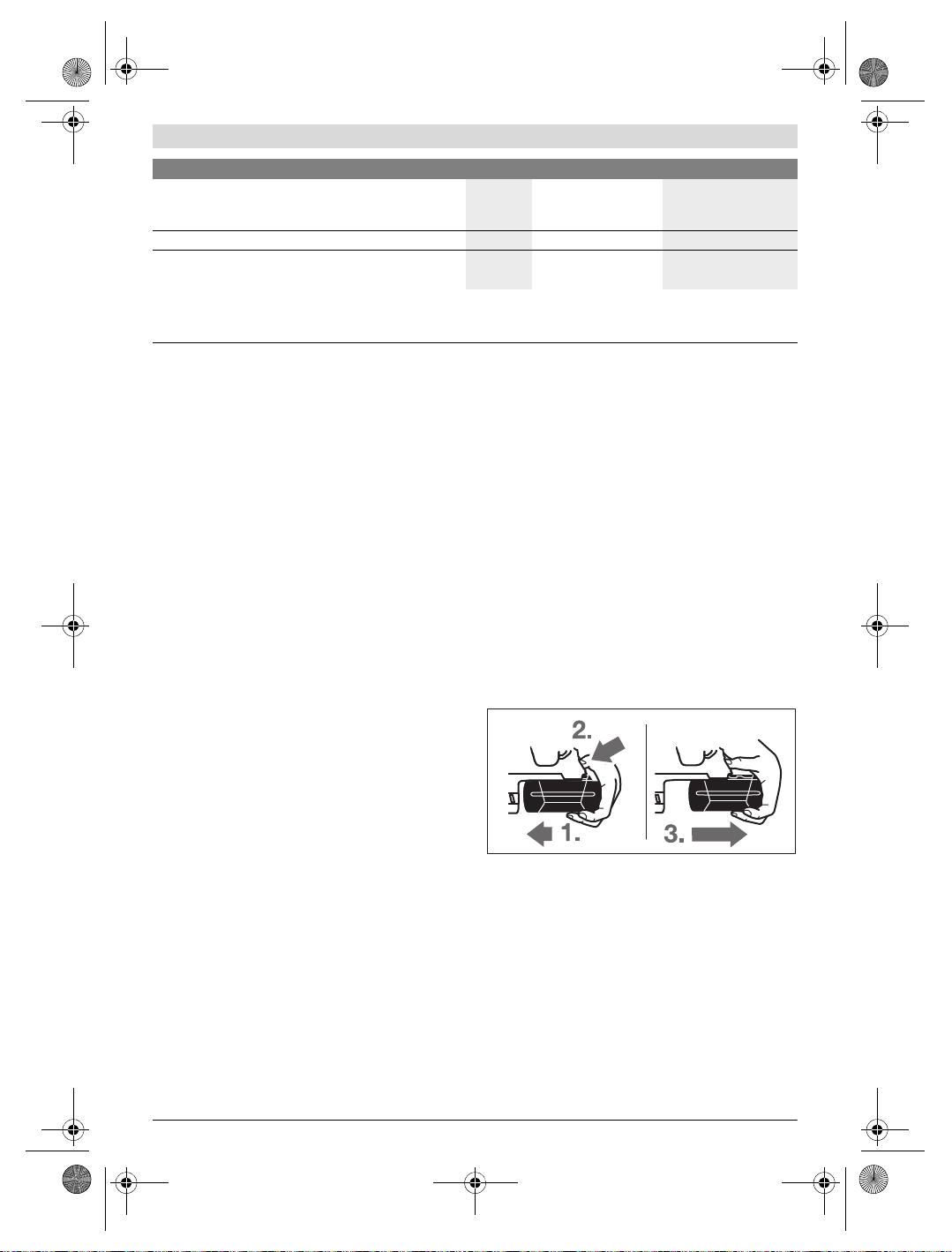
OBJ_BUCH-283-013.book Page 26 Thursday, September 29, 2016 8:34 AM
26 | Français
Marteau perforateur GBH 36 V-LI Plus GBH 36 VF-LI Plus
Plage de températures autorisées
–pendant la charge
– pendant le fonctionnement
2)
et pour le stockage
Accus recommandés
Chargeurs recommandés
1) selon l’accumulateur utilisé
2) performances réduites à des températures <0 ° C
Caractéristiques techniques déterminées avec l’accu fourni avec l’appareil.
°C
°C
0... +45
–20...+50
0...+45
–20...+50
GBA 36V ... GBA 36V ...
AL36..
GAL 36..
AL36..
GAL 36..
Niveau sonore et vibrations
Valeurs d’émissions sonores déterminées selon la norme
EN 60745-2-6.
Les mesures réelles (A) des niveaux sonores de l’appareil
sont : Niveau de pression acoustique 90 dB(A) ; niveau d’intensité acoustique 101 dB(A). Incertitude K=3 dB.
Porter une protection acoustique !
Valeurs totales des vibrations a
axes directionnels) et incertitude K relevées conformément à
la norme EN 60745-2-6 :
Perforation dans le béton : a
Burinage : ah= 9,5 m/s2, K= 1,5 m/s
Perçage dans le métal : ah<2,5m/s2, K= 1,5 m/s
Vissage : ah<2,5m/s2, K= 1,5 m/s
(somme vectorielle des trois
h
=14,5m/s2, K= 1,5 m/s
h
2
2
2
2
Le niveau d’oscillation indiqué dans ces instructions d’utilisation a été mesuré conformément à la norme EN 60745 et peut
être utilisé pour une comparaison d’outils électroportatifs. Il
est également approprié pour une estimation préliminaire de
la charge vibratoire.
Le niveau d’oscillation correspond aux utilisations principales
de l’outil électroportatif. Si l’outil électrique est néanmoins
utilisé pour d’autres applications, avec différents accessoires
ou d’autres outils de travail ou s’il est mal entretenu, le niveau
d’oscillation peut être différent. Ceci peut augmenter considérablement la charge vibratoire pendant toute la durée de
travail.
Pour une estimation précise de la charge vibratoire, il est recommandé de prendre aussi en considération les périodes
pendant lesquelles l’appareil est éteint ou en fonctionnement,
mais pas vraiment utilisé. Ceci peut réduire considérablement la charge vibratoire pendant toute la durée de travail.
Déterminez des mesures de protection supplémentaires pour
protéger l’utilisateur des effets des vibrations, telles que par
exemple : Entretien de l’outil électrique et des outils de travail, maintenir les mains chaudes, organisation des opérations de travail.
Montage
Chargement de l’accu (voir figure A)
N’utilisez que les chargeurs indiqués sur la page des ac-
cessoires. Seuls ces chargeurs sont adaptés à l’accu à ions
lithium utilisé dans votre outil électroportatif.
Note : L’ac cu e st f our ni en éta t de cha rge faib le. Afi n de gar antir la puissance complète de l’accu, chargez complètement
l’accu dans le chargeur avant la première mise en service.
La batterie Lithium-ion peut être rechargée à tout moment,
sans que sa durée de vie n’en soit réduite. Le fait d’interrompre le processus de charge n’endommage pas la batterie.
Grâce à la Protection Electronique des Cellules « Electronic
Cell Protection (ECP) », l’accu à ions lithium est protégé
contre une décharge profonde. Lorsque l’accumulateur est
déchargé, l’outil électroportatif s’arrête grâce à un dispositif
d’arrêt de protection : L’outil de travail ne tourne plus.
Après la mise hors fonctionnement automatique de
l’outil électroportatif, n’appuyez plus sur l’interrupteur
Marche/Arrêt. Ceci pourrait endommager l’accu.
Retirer l’accu
L’accu 11 dispose de 2 positions de verrouillage qui doivent
éviter que l’accu puisse sortir si l’on appuie sur la touche de
déverrouillage de l’accu 18 par mégarde. Tant que l’accu reste
en place dans l’outil électroportatif, un ressort le maintient en
position.
Pour enlever l’accu 11 :
– Poussez l’accu contre le pied de l’outil électroportatif (1.)
et en même temps, appuyez sur la touche de déverrouillage 18 (2.).
– Retirez l’accu de l’outil électroportatif jusqu’à ce qu’un trait
rouge apparaisse (3.).
– Appuyez de nouveau sur la touche de déverrouillage 18 et
retirez complètement l’accu.
Voyant lumineux indiquant l’état de charge de l’accu
Les trois LED vertes du voyant lumineux 20 indiquent l’état de
charge de l’accu 11. Pour des raisons de sécurité, l’interrogation de l’état de charge n’est possible que quand l’outil électroportatif est à l’arrêt.
1 609 92A 2CS | (29.9.16) Bosch Power Tools
OBJ_BUCH-283-013.book Page 27 Thursday, September 29, 2016 8:34 AM
– Appuyer sur la touche 21 pour indiquer l’état de charge de
l’accu (également possible lorsque l’accu a été retiré de
l’appareil). Le voyant lumineux s’éteint automatiquement
au bout de 5 secondes environ.
LED Capacité
Lumière permanente 3 x verte 2/3
Lumière permanente 2 x verte 1/3
Lumière permanente 1 x verte <1/3
Lumière clignotante 1 x verte Réserve
Si aucune LED n’est allumée après que la touche 21 a été appuyée, l’accu est défectueux et doit être remplacé.
Lors du processus de charge les 3 LED vertes s’allument l’une
après l’autre et s’éteignent pour une courte durée. L’accu est
complètement chargé lorsque les 3 LED vertes restent
constamment allumées. Les 3 LED vertes s’éteignent environ
5 minutes après la charge complète de l’accu.
Poignée supplémentaire
N’utilisez l’outil électroportatif qu’avec la poignée sup-
plémentaire 16.
Pivoter la poignée supplémentaire (voir figure B)
La poignée supplémentaire 16 peut être basculée dans n’importe quelle position, afin d’obtenir une position de travail
sûre et peu fatigante.
– Tournez la pièce inférieure de la poignée supplémentaire
16 dans le sens inverse des aiguilles d’une montre et orientez la poignée supplémentaire 16 vers la position souhaitée. Ensuite, resserrez la pièce inférieure de la poignée
supplémentaire 16 en la tournant dans le sens des aiguilles
d’une montre.
Veiller à ce que la bande de serrage de la poignée supplémentaire se trouve bien dans la rainure du carter prévue à cet
effet.
Choisir mandrin porte-foret et outils
Pour le perçage en frappe et le burinage, des outils SDS-plus
sont nécessaires qui sont mis en place dans le porte-foret
SDS-plus.
Pour le perçage sans frappe du bois, du métal, de la céramique ou de matières plastiques ainsi que pour le vissage, des
outils sans SDS-plus (par ex. forets à queue cylindrique) sont
utilisés. Pour ce type d’outil, vous avez besoin d’un mandrin à
serrage rapide ou d’un mandrin à couronne dentée.
Insertion/retrait du mandrin à clé
(GBH 36 V-LI Plus)
Afin de pouvoir travailler avec des outils sans SDS-plus (par
ex. mèches à queue cylindrique), vous devez monter un mandrin porte-foret approprié (mandrin à c ouronne dentée ou de
serrage rapide, accessoires).
Monter un mandrin à couronne dentée (voir figure C)
– Vissez le dispositif de fixation SDS-plus 24 dans un man-
drin à couronne dentée 23. Fixez le mandrin à couronne
dentée 23 au moyen de la vis de fixation 22. Attention, la
vis de fixation a un filet à gauche.
Insérer un mandrin à couronne dentée (voir figure C)
– Nettoyez l’emmanchement du dispositif de fixation et
graissez-le légèrement.
– Enfoncez le mandrin à couronne dentée par le dispositif de
fixation en le tournant dans le porte-outil jusqu’à ce qu’il
verrouille automatiquement.
– Contrôlez qu’il est bien verrouillé en tirant sur le mandrin à
couronne dentée.
Retirer un mandrin à couronne dentée
– Poussez la douille de verrouillage 5 vers l’arrière et retirez
le mandrin à couronne dentée 23.
Enlever/mettre en place le mandrin
interchangeable (GBH 36 VF-LI Plus)
Le mandrin interchangeable SDS-plus 2 peut facilement être
remplacé par le mandrin interchangeable à serrage rapide 1
fourni avec l’appareil.
Enlever le mandrin interchangeable (voir figure D)
– Tirer fermement la bague de verrouillage du mandrin inter-
changeable 6 vers l’arrière, la maintenir dans cette position et sortir le mandrin interchangeable SDS-plus 2 ou le
mandrin interchangeable à serrage rapide 1 vers l’avant.
– Après avoir extrait le mandrin interchangeable, éviter tout
encrassement.
Mettre en place le mandrin interchangeable
(voir figure E)
N’utiliser qu’un équipement d’origine spécifique au
modèle et respecter le nombre des rainures code 26.
Seuls des mandrins interchangeables avec deux rainures code sont admissibles.Seuls des mandrins interchangeables avec deux ou trois rainures code sont admissibles. Au cas où un mandrin interchangeable
inapproprié pour cet outil électroportatif serait utilisé, l’outil électroportatif peut tomber pendant le service.
– Avant sa mise en place, nettoyer le mandrin interchan-
geable et graisser légèrement l’extrémité.
– Prendre le mandrin interchangeables SDS-plus 2 ou le
mandrin interchangeable à serrage rapide 1 à pleine main.
Engager le mandrin interchangeable dans la fixation du
mandrin 25 par un léger mouvement de rotation, jusqu’à
ce qu’il s’encliquette de manière audible.
– Le mandrin interchangeable s’encliquette de lui-même.
Contrôler que l’outil soit bien encliqueté en tirant sur le
mandrin interchangeable.
Changement d’outil
Le capuchon anti-poussière 4 empêche dans une large mesure la poussière de pénétrer dans le porte-outil pendant le
service de l’appareil. Lors du montage de l’outil, veillez à ne
pas endommager le capuchon anti-poussière 4.
Remplacez immédiatement un capuchon anti-pous-
sière endommagé. Il est recommandé de faire effectuer ce travail par un service après-vente.
Français | 27
Bosch Power Tools 1 609 92A 2CS | (29.9.16)
OBJ_BUCH-283-013.book Page 28 Thursday, September 29, 2016 8:34 AM
28 | Français
Changement d’outil (SDS-plus)
Mettre un outil de travail SDS-plus en place (voir figure F)
Grâce au mandrin de perçage SDS-plus, il est possible de
remplacer l’outil de travail facilement et confortablement
sans avoir à utiliser d’outil supplémentaire.
– GBH 36 VF-LI Plus: Mettre le mandrin interchangeable
SDS-plus 2 en place.
– Nettoyez l’extrémité de l’outil, et graissez-le légèrement.
– Introduisez l’outil de travail dans le porte-outil en le tour-
nant jusqu’à ce qu’il s’encliquette automatiquement.
– Vérifiez si l’outil est bien encliqueté en tirant sur ce dernier.
Les outils de travail SDS-plus utilisés dans ce système ne sont
pas rigidement fixés, ils peuvent être librement bougés. Ceci
provoque un faux-rond au fonctionnement à vide qui n’a cependant aucun effet sur l’exactitude du perçage puisque le foret se centre automatiquement pendant le perçage.
Retirer un outil de travail SDS-plus (voir figure G)
– Poussez la douille de verrouillage 5 vers l’arrière et sortez
l’outil de travail.
Changement d’outil (sans SDS-plus)
(GBH 36 V-LI Plus)
Montage des outils de travail (voir figure H)
Note : N’utilisez pas d’outils sans SDS-plus pour le perçage en
frappe ou le burinage ! Les outils sans SDS-plus et leurs mandrins seront endommagés lors du perçage en frappe ou du burinage.
– Mettez un mandrin à couronne dentée 23 en place (voir
« Insertion/retrait du mandrin à clé », page 27).
– Ouvrez le mandrin à clé à couronne dentée 23 par un mou-
vement de rotation jusqu’à ce que l’outil puisse être monté.
Montez l’outil.
– Enfoncez la clé de mandrin dans les alésages correspon-
dants du mandrin à couronne dentée 23 et serrez fermement l’outil de manière régulière.
– Tournez le stop de rotation/de frappe 13 pour le mettre
dans la position « perçage ».
Sortir l’outil de travail (voir figure I)
– Tournez la douille du mandrin à couronne dentée 23 à
l’aide de la clé de mandrin dans le sens des aiguilles d’une
montre jusqu’à ce que l’outil de travail puisse être retiré.
Changement d’outil (sans SDS-plus)
(GBH 36 VF-LI Plus)
Montage des outils de travail (voir figure J)
Note : N’utilisez pas d’outils sans SDS-plus pour le perçage en
frappe ou le burinage ! Les outils sans SDS-plus et leurs mandrins seront endommagés lors du perçage en frappe ou du burinage.
– Mettez le mandrin à serrage rapide 1 en place.
– Tenir fermement l’anneau de retenue du mandrin inter-
changeable à serrage rapide 29. Ouvrir le porte-outil en
tournant la douille avant 28 jusqu’à ce que l’outil puisse
être monté. Bien tenir l’anneau de retenue 29 et tourner la
douille avant 28 av ec f or ce e n d ire ct ion de la f lè che ju squ ’à
ce que des grincements soient distinctement audibles.
1 609 92A 2CS | (29.9.16) Bosch Power Tools
– Contrôler que l’outil soit bien fixé en tirant dessus.
Note : Si le porte-outil a été ouvert à fond, il est possible que
des grincements se font entendre lorsque le porte-outil est
vissé et que le porte-outil ne se ferme pas.
Dans un tel cas, tourner la douille avant 28 une fois dans le
sens inverse de la flèche. Ensuite, il est possible de fermer le
porte-outil.
– Tournez le stop de rotation/de frappe 13 pour le mettre
dans la position « perçage ».
Sortir l’outil de travail (voir figure K)
– Tenir fermement l’anneau de retenue du mandrin inter-
changeable à serrage rapide 29. Ouvrir le porte-outil en
tournant la douille avant 28 dans le sens de la flèche jusqu’à ce que l’outil puisse en être extrait.
Aspiration des poussières avec GDE 16 Plus
(accessoire)
Les poussières de matériaux tels que peintures contenant
du plomb, certains bois, minéraux ou métaux, peuvent être
nuisibles à la santé. Entrer en contact ou aspirer les poussières peut entraîner des réactions allergiques et/ou des
maladies respiratoires auprès de l’utilisateur ou de personnes se trouvant à proximité.
Certaines poussières telles que les poussières de chêne ou
de hêtre sont considérées comme cancérigènes, surtout
en association avec des additifs pour le traitement du bois
(chromate, lazure). Les matériaux contenant de l’amiante
ne doivent être travaillés que par des personnes qualifiées.
– Si possible, utilisez un dispositif d’aspiration des pous-
sières approprié au matériau.
– Veillez à bien aérer la zone de travail.
– Il est recommandé de porter un masque respiratoire
avec un niveau de filtration de classe P2.
Respectez les règlements spécifiques aux matériaux à traiter en vigueur dans votre pays.
Evitez toute accumulation de poussières à l’emplace-
ment de travail. Les poussières peuvent facilement s’en-
flammer.
Pour l’aspiration des poussières, un adaptateur d’aspiration
GDE 16 Plus (accessoire) est requis.
L’aspirateur doit être approprié au matériau à travailler.
Pour l’aspiration de poussières particulièrement nuisibles à la
santé, cancérigènes ou sèches, utilisez des aspirateurs spécifiques.
Mise en marche
Mise en service
Montage de l’accu
– Mettez le commutateur du sens de rotation 8 en position
médiane pour éviter toute mise en marc he accident elle de
l’outil électroportatif.
– Introduisez l’accu chargé 11 par l’arrière dans le pied de
l’outil électroportatif. Enfoncez complètement l’accu dans
le pied jusqu’à ce que le trait rouge ne soit plus visible et
que l’accu soit bien verrouillé.
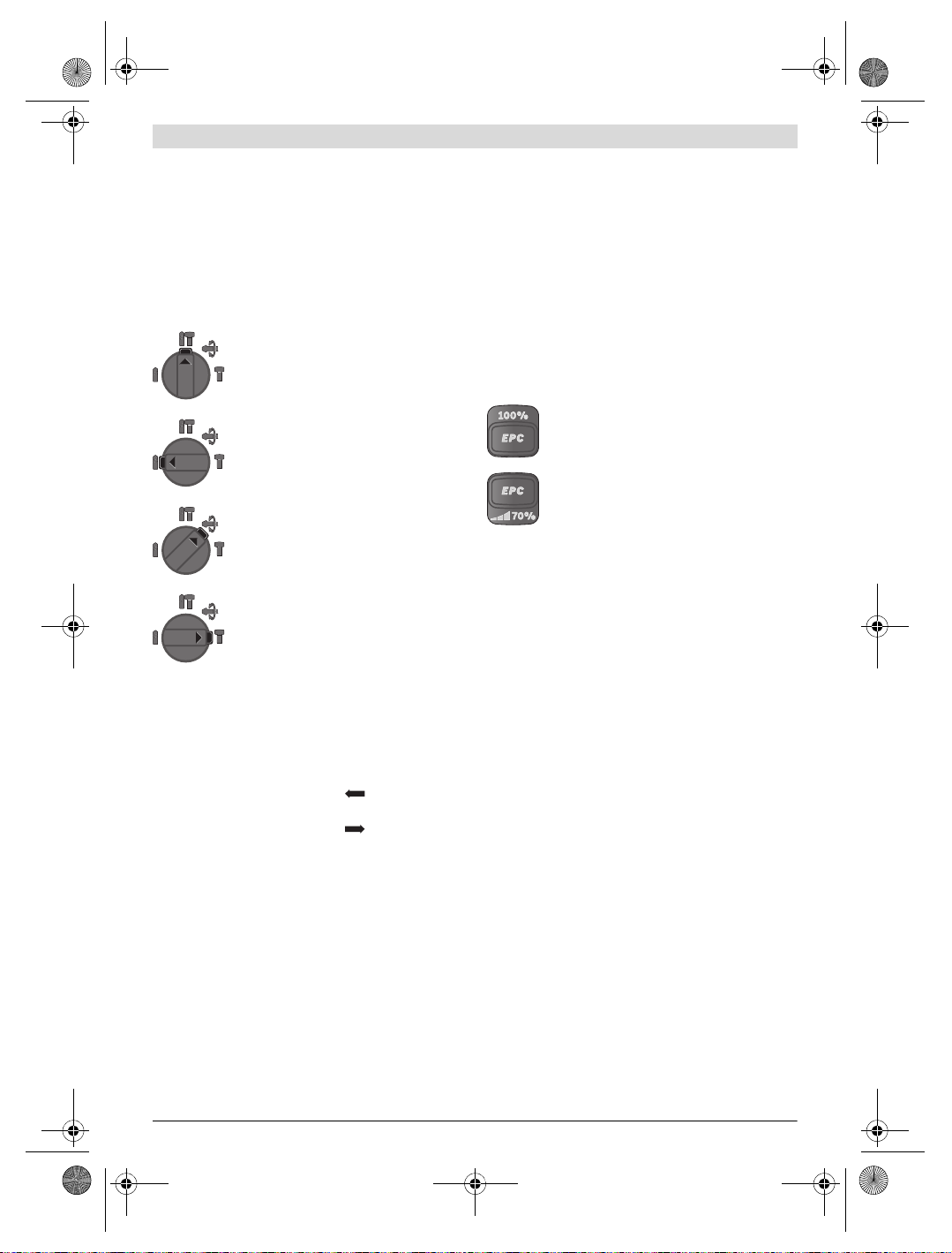
OBJ_BUCH-283-013.book Page 29 Thursday, September 29, 2016 8:34 AM
Réglage du mode de fonctionnement
Au moyen du stop de rotation/de frappe 13, sélectionnez le
mode d’exploitation souhaité de l’outil électroportatif.
Note : Ne changez le mode de fonctionnement que lorsque
l’outil électroportatif est éteint ! Sinon, l’outil électroportatif
pourrait être endommagé.
– Pour changer de mode d’exploitation, appuyer sur la
touche de déverrouillage 12 et tourner le stop de rotation/de frappe 13 dans la position souhaitée jusqu’à ce
qu’il s’encliquette de façon perceptible.
Réglage de la vitesse de rotation/de la fréquence de
frappe
Vous pouvez régler en continu la vitesse de rotation/ la fréquence de frappe de l’outil électroportatif en fonction de la
pression exercée sur l’interrupteur de Marche/Arrêt 10.
Une légère pression sur l’interrupteur Marche/Arrêt 10 entraîne une faible vitesse de rotation/fréquence de frappe.
Plus la pression augmente, plus la vitesse de rotation/la fréquence de frappe est élevée.
Electronic Precision Control (EPC) (voir figure L)
La fonction EPC facilite le travail avec percussion dans les ma-
Position pour le perçage en frappe dans le
béton et dans la pierre naturelle
tériaux fragiles, grâce à un démarrage en douceur et une vitesse de travail réduite.
– Placez le commutateur EPC 30 dans la position souhaitée.
Français | 29
Position pour le perçage san s fr appe du b ois,
du métal, de la céramique ou de matières
plastiques ainsi que pour le vissage
Position Vario-Lock pour le réglage de la position du burin
Dans cette position, le stop de rotation/de
frappe 13 ne s’encliquette pas.
Position pour le burinage
Sélection du sens de rotation
Le commutateur de sens de rotation 8 permet d’inverser le
sens de rotation de l’outil électroportatif. Ceci n’est cependant pas possible, quand l’interrupteur Marche/Arrêt 10 est
en fonction.
Rotation droite : Poussez le commutateur de sens de sélection 8 jusqu’en butée dans la position .
Rotation gauche : Poussez le commutateur de sen s de sélection 8 jusqu’en butée dans la position .
Mettez toujours le sens de rotation sur la droite pour le perçage en frappe, le perçage et le burinage.
Mise en Marche/Arrêt
Afin d’économiser l’énergie, ne mettez l’outil électroportatif
en marche que quand vous l’utilisez.
–Pour mettre en marche l’outil électroportatif, appuyez sur
l’interrupteur Marche/Arrêt 10.
Lors de la première mise en marche de l’outil électroportatif,
un retard de démarrage est possible parce que l’électronique
de l’outil électroportatif doit d’abord se configurer.
–Pour arrêter l’outil électroportatif, relâchez l’interrupteur
Marche/Arrêt 10.
Position pour une vitesse de travail maximale
Position pour un démarrage en douceur et une vitesse de travail réduite
Accouplement de surcharge
Dès que l’outil de travail se coince ou qu’il s’accroche,
l’entraînement de la broche est interrompu. En raison
des forces pouvant en résulter, tenez toujours bien
l’outil électroportatif des deux mains et veillez à garder
une position stable et équilibrée.
Arrêtez immédiatement l’outil électroportatif et déblo-
quez l’outil de travail lorsque l’appareil électroportatif
coince. Lorsqu’on met l’appareil en marche, l’outil de
travail étant bloqué, il peut y avoir de fortes r
Dispositif d’arrêt rapide
(ERC)
éactions.
Le dispositif d’arrêt rapide permet de mieux contrôler l’outil
électroportatif. Une rotation imprévue de l’outil électroportatif autour de l’axe de perçage arrête l’outil.
L’activation du dispositif d’arrêt rapide est signalée par le clignotement de l’éclairage 14 sur l’outil électroportatif.
–Pour la remise en marche, relâchez l’interrupteur
Marche/Arrêt puis actionnez-le à nouveau.
L’arrêt rapide ne peut se déclencher que quand l’outil
électroportatif fonctionne à la vitesse maximale et qu’il
peut tourner librement autour de l’axe du foret. Sélec-
tionnez pour cela une position de travail appropriée. L’arrêt rapide ne peut sinon pas fonctionner.
Affichage contrôle de température
La LED rouge de l’affichage contrôle de température 19 signale que l’accu ou l’électronique de l’outil électroportatif
(l’ accu é tant m is en place ) ne s e trou vent p as da ns la p lage de
température optimale. Dans un tel cas l’outil électroportatif
ne tourne pas du tout ou pas à pleine puissance.
Bosch Power Tools 1 609 92A 2CS | (29.9.16)

OBJ_BUCH-283-013.book Page 30 Thursday, September 29, 2016 8:34 AM
30 | Français
Contrôle de température de l’accu :
– La LED rouge 19 est constamment allumée lorsque l’accu
est inséré dans le chargeur. L’accu se trouve en dehors de
la plage de température de charge admissible de 0 ° C à
45 ° C et ne peut pas être chargé.
– La LED rouge 19 clignote lors de l’actionnement de la
touche 21 ou de l’interrupteur Marche/Arrêt 10 (quand
l’accu est en place) : l’accu se trouve en dehors de la plage
de températures de fonctionnement admissible.
– L’outil électroportatif s’éteint lorsque la température d’ac-
cu est supérieure à 70 °C et reste éteint jusqu’à ce que l’accu se retrouve dans la plage de température optimale.
Contrôle de température de l’électronique de l’outil électroportatif :
– La LED rouge 19 est constamment allumée lorsque l’on ap-
puie sur l’interrupteur Marche/Arrêt 10. La température
de l’électronique de l’outil électroportatif est inférieure à
5 ° C ou supérieure à 75 ° C.
– L’électronique de l’outil électroportatif s’éteint lorsque la
température est supérieure à 90 ° C jusqu’à ce qu’elle se
retrouve dans la plage de température de service admissible.
Instructions d’utilisation
Réglage de la profondeur de perçage (voir figure M)
La butée de profondeur 17 permet de déterminer la profondeur de perçage souhaitée X.
– Appuyez sur la touche de réglage de la butée de profon-
deur 15 et placez la butée de profondeur dans la poignée
supplémentaire 16.
Le striage de la butée de profondeur 17 doit être orienté
vers le bas.
– Poussez à fond l’outil de travail SDS-plus dans le porte-ou-
til SDS-plus 3. Sinon, la mobilité de l’outil SDS-plus pourrait conduire à un réglage erroné de la profondeur de perçage.
– Sortez la butée de profondeur jusqu’à ce que la distance
entre la pointe du foret et la pointe de la butée de profondeur corresponde à la profondeur de perçage souhaitée X.
Modification de la position du burin (Vario-Lock)
Il est possible d’arrêter le burin dans 36 positions. Ceci permet de se mettre dans la position de travail optimale souhaitée.
– Montez le burin dans le porte-outil.
– Tournez le stop de rotation/de frappe 13 pour le mettre
dans la position « Vario-Lock » (voir « Réglage du mode de
fonctionnement », page 29).
– Tournez le porte-outil dans la position du burin souhaitée.
– Tournez le stop de rotation/de frappe 13 pour le mettre
dans la position « burinage ». Le porte-outil est ainsi
arrêté.
– Mettez le sens de rotation sur la droite pour le burinage.
Mettre des embouts de vissage en place (voir figure N)
Posez l’outil électroportatif sur la vis/sur l’écrou seule-
ment lorsque l’appareil est arrêté. Les outils de travail en
rotation peuvent glisser.
Pour pouvoir utiliser des embouts de vissage, vous avez besoin d’un porte-outil universel 31 avec dispositif de fixation
SDS-plus (accessoire).
– Nettoyez l’emmanchement du dispositif de fixation et
graissez-le légèrement.
– Enfoncez le porte-outil universel en le tournant dans le
porte-outil jusqu’à ce qu’il verrouille automatiquement.
– Contrôlez qu’il est bien verrouillé en tirant sur le porte-outil
universel.
– Mettez un embout de vissage dans le porte-outil universel.
N’utilisez que des embouts de vissage appropriés à la tête
de vis que vous voulez utiliser.
– Pour enlever le porte-outil universel, poussez la douille de
verrouillage 5 vers l’arrière et sortez le porte-outil universel
31 du porte-outil.
Dispositif d’amortissement des vibrations
Le dispositif intégré pour l’amortissement des vibrations réduit les vibrations se produisant lors du travail.
La surface softgrip de la poignée évite un glissement de la
main et permet ainsi une meilleure maniabilité de l’outil électroportatif.
Indications pour le maniement optimal de l’accu
Protégez l’accu de l’humidité et de l’eau.
Ne stockez l’accu que dans la plage de température de
–20 ° C à 50 ° C. Ne stockez pas l’accu trop longtemps dans
une voiture par ex. en été.
Nettoyez de temps en temps les orifices de ventilation de l’accu à l’aide d’un pinceau doux, propre et sec.
Si l’autonomie de l’accu diminue considérablement après les
recharges effectuées, cela signifie que l’accu est usagé et qu’il
doit être remplacé.
Respectez les indications concernant l’élimination.
Entretien et Service Après-Vente
Nettoyage et entretien
Avant d’effectuer des travaux sur l’appareil (p.ex. tra-
vaux d’entretien, changement d’outils, etc.) et pour le
transporter ou le stocker, retirez l’accu de l’appareil
électroportatif. Il y a risque de blessure lorsqu’on appuie
par mégarde sur l’interrupteur Marche/Arrêt.
Veillez à ce que l’outil électroportatif ainsi que les ouïes
de ventilation soient toujours propres afin d’obtenir un
travail impeccable et sûr.
Remplacez immédiatement un capuchon anti-pous-
sière endommagé. Il est recommandé de faire effectuer ce travail par un service après-vente.
– Nettoyez le porte-outil 3 après chaque utilisation.
1 609 92A 2CS | (29.9.16) Bosch Power Tools
 Loading...