

Bosch G3A-PSU1-4, G3A-PSU1-16, G3A-PSU1-8 Installation Instructions Manual
Das Blitzsymbol im gleichseitigen
Dreieck soll den Benutzer auf nicht
isolierte "Hochspannun gen" im
Gehäuse aufmerksam machen, die
eventuell star k genug sind, einen
elektrischen Schlag zu verursachen.
Das Aufrufezeichen im gleichseitigen
Dreieck soll den Benutzer auf
wichtige Bedienung s - un d
Wartungsanle itungen in der dem
Gerät beigefügten Literatur
aufmerksam machen.
Warnung: Um Feuer oder
elektrische Schläge zu vermeiden,
setzen Sie das Gerät niemals Regen
oder Feuchtigkeit aus.
Achtung: Die Installation soll nur von
qualifiziertem Kundendienstpersonal
gemäss jeweilig zutreffender
Elektrovorschriften ausgeführt
werden.
Netzanschluss: Geräte mit oder ohne
Netzschalter haben Spannung am
Gerät anliegen, sobald der
Netzstecker in die Steckdose gesteckt
wird. Das Gerät ist jedoch nur
betriebsbereit, wenn der Netzschalter
(EIN/AUS) auf EIN steht. Wenn man
das Netzkabel aus de r Ste ck do s e
zieht, dann ist die
Spannungszuführung zum Gerät
El simbolo repres e ntado po r un
relámpago con una punta de flecha dentro
de un triángulo equilátero se muestra con
el objetivo de alertar al usuario que
existen "voltages periculosos" sin
aislamiento dento de la cubierta de la
unidad. Dichos voltages pueden ser de tal
magnitud que constituyen un riesgo de
choque eléctrico a personas.
El simbolo de exclamación dentro de un
triángulo equilátero se muestra con el
objetivo de alertar al usuario de que
instrucciones de operación y
mantenimiento importantes acompañan
al equipo.
Peligro: Para evitar el peligro de
incendio ó choque eléctrico, no
exponga a la lluvia o humedad equipos
que no han sido para uso exteri or .
Attencion: La instalacion de este equipo
debe ser realizada por personal
capacitado, solo en acuerdo y en
cumplimiento de normas del "National
Electrical Code" (Codigo Electrico
Nacional) o las normes del Gobierno
Para Desconectar la Alimentación:
Unidades no equipadas con interrupores
ON/OFF son alimentadas cuando el cable
de alimentación es connectado a la
corriente eléctrica. Las unidades
equipadas con interruptores son
alimentadas de igual forma, pero
adicionalmente requiren que el
interruptor esté posicionado en ON. El
cable de alimentaion es el medio
principal de desconexión del equipo.
Vorsicht: Um einen elektrischen Schlag zu
vermeiden, Abdecku n g nicht entfe rne n. Wartunge n
aller Art qualifiziertem Pe rsonal überlassen.
Precaución: Para reducir el riego de choque eléctrico,
favor no abrir la cubierta. Este equipo no consta de
piezas o partes que requiren servicio o mantenimieto.
Para reparaciones favor referirse a un tecnico calificado.
RIES G O DE CH O QUE
ELECTRICO. NO ABRIR !
PRECAUCION
SECURITE
G3A-PSU1-4, G3A-PSU1-8, G3A-PSU1-16
Power Supplies for AutoDomes
1. UNPACKING
Unpack carefully. This is electrical equipment and should be handled with care.
Check for the following items:
* Verify the unit model number. * 4 Wood screws.
If an item appears to have been damaged in sh ip ment, replace it properly in its carton and
notify the shipper. If any items are missing, notify your Bosch Sales Representative or
Customer Service.
The shipping carton is the safest container in which the unit may be transported. Save it for
possible future use.
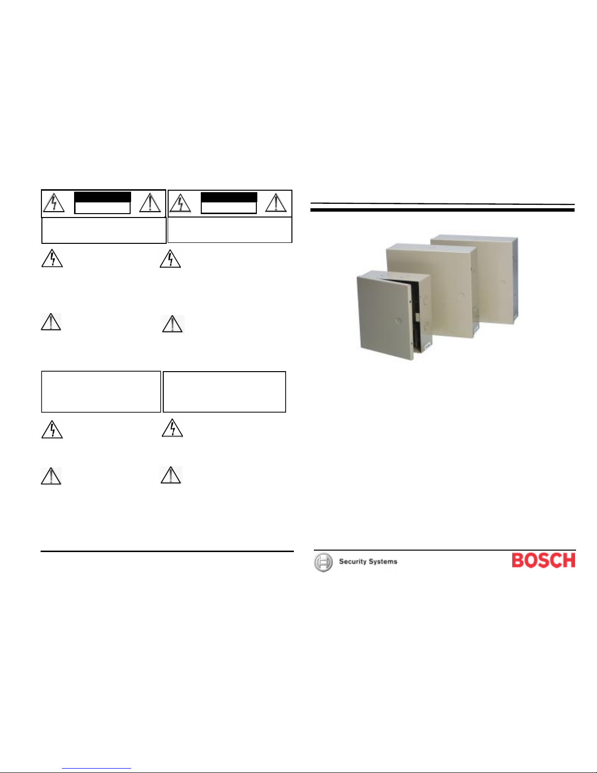
2. DESCRIPTION
The G3A-PS U 1 - 4 , G3A- PSU1-8 and
G3A-PSU1-16 are four, eight and sixteen AutoDome power supplies. They deliver 28V AC,
60 Hz at up to 1.85A maximum for any individu al circuit. They include on-board surge
protection and an on/off switch.
Total Available Current:
G3A-PSU1-4: 3.5 A
G3A-PSU1-8: 6.5 A
G3A-PSU1-16: 13 A
Installation Instructions
© 2003 Bosch Security Systems 3935 890 44111 2/03
850 Greenfield Road, Lancaster, PA 17601 USA Installation Instructions Page 4 of 4
Tel: 800-326-3270 Fax: 1-717-735-6560 G3A-PSU1-4, G3A-PSU1-8, G3A-PSU1-16
Printed in USA
RISIKO EIN ES E LE KT RISC HEN
SCHLAGES. NICHT ÖFFNE N
VORSICHT
SICHERHEITSVORKEHRUNGEN
The lightning flash with an arrowhead
symbol within an equilateral triangle
is intended to alert the user to the
presence of uninsulated "dangerous
voltage" within the product's
enclosure that might be of sufficient
magnitude to constitute a risk of
electric shock to per so ns .
The exclamation point within an
equilateral triangle is intended to alert
the user to presence of important
operating and maintenance (servicing )
instructions in the lite r ature's
accompanying the appliance.
Warning: To prevent fire or shock
hazard, do not expose the units not
specifically designed for outdoor
use to rain or moisture.
Attention: Installation should be
performed by qualified service
personnel only in accordance with the
National Electrical Code or applicable
local codes.
Power Disconnect: Units with or
without ON-OFF switches have power
supplied to the unit whenever the
power cord is oinserted into the power
source; however, the unit is operational
only when the ON-OF F switch is in the
ON position. The power cord is the
main power disconnect for all units.
Léclair fléché dans un triangle
équilatéral avertit l'utilisateur de la
présence d'une "tension dangereuse" non
isolée à l'intérieur de l'appareil et d'une
valeur suffisante pour constitu er un
risque d'électrocution.
Le point d'exclamati o n contenu dans un
triangle avertit l'utilisateur de la
présence, dans la documentation qui
accompagne l'appareil, de consignes
d'utilisation et de maintenance
importantes.
Attention: Pour éviter le risque
d'électrocution ou d'incendie, ne pas
exposer à la pluie ou à l'humidite un
appareil non conçu pour une utilisation
éxterieure.
Attention: L'installation doit être
effectuée uniquement par du personnel
de service qualifié conformément à la
réglementation du Code Electrique
National ou à la réglementation locale.
Disjonction de l'alimentati on. Les
appareils avec ou sans commutateurs
On_OFF sont alimentés à chaque fois
que le cordon d'alimentation est branché
à la source d'alimentation; toutefois, les
appareils disposant de commutateurs
ON-OFF ne fonctionnent que lorsque le
commutateur ON-OFF est sur la position
ON. Le cordon d'alimentation est la
disjonction d'alim e n tation principale pour
tous les appareils.
Cauti on: To re duce the ri s k of elect ri cal sho ck, do n o t
open co vers. No user serviceable parts insi de. Ref e r
servicing to qualified service personnel.
RISK OF ELECTRIC
SHOCK. DO NOT OPEN
CAUTION
SAFETY PRECAUTIONS
Danger: Pour éviter tout risque d'électrocution, ne pas ouvrir
le boîtier. Il n'y a pas de pi è ces rempl açables à l'intérieur .
Pour toute révision, s'adre sser à un technicien spécialisé.
RIS QUE DE CH OC ELE CT RI QUE .
NE PAS OUVRIR
CAUTION
SECURITE
5. SERVICE
If the unit ever needs repair service, the customer should contact the nearest Bosch Service
Center for authorization to return and shipping instructions.
Service Centers
U.S.A: Phone: 800-366-2283 or 408-956-3895; Fax: 800-366-1329 or 408-956-3896
email: NationalServiceCenter@ca.slr.com
Canada: 514-738-2434
Europe, Middle East & Asia Pacific Regions: 32-1-440-0711
For additional information, see www.boschsecuritysystems.com
3. INSTALLATION
3.1 Tools Required
Medium size flat blade screwdriver. Electric drill
3.2 Mounting
1. Select a dry, secure location to mount the unit. Be sure to remove any knock-outs that
will be used before permanently mounting the cabinet.
2. Place the cabinet on the wall an d mark the four screw locations. Set the cabinet aside
and drill guide holes for the mounting screws.
3. Place the cabinet on the wall an d secure with screws.
4. Do not connect AC power to the unit at this time. Wire AutoDomes, using 1 mm (18
AWG) two conductor wire, starting with the first pair of terminals labeled COMMON
POWER and FUSED POWER. Connect the other end of the two conductor wire to the
camera.
5. Repeat the connections to the power supply terminals and all remaining AutoDomes;
observe polarity in order to maintain vertical phase alignment.
6. Check all wiring. Be sure the switch is in the lower OFF position.
7. Plug the unit into an unswitched 120V AC, 60 Hz outlet. Turn the switch ON and note
that the LED indicator is illuminated. Power is now available for the cameras.
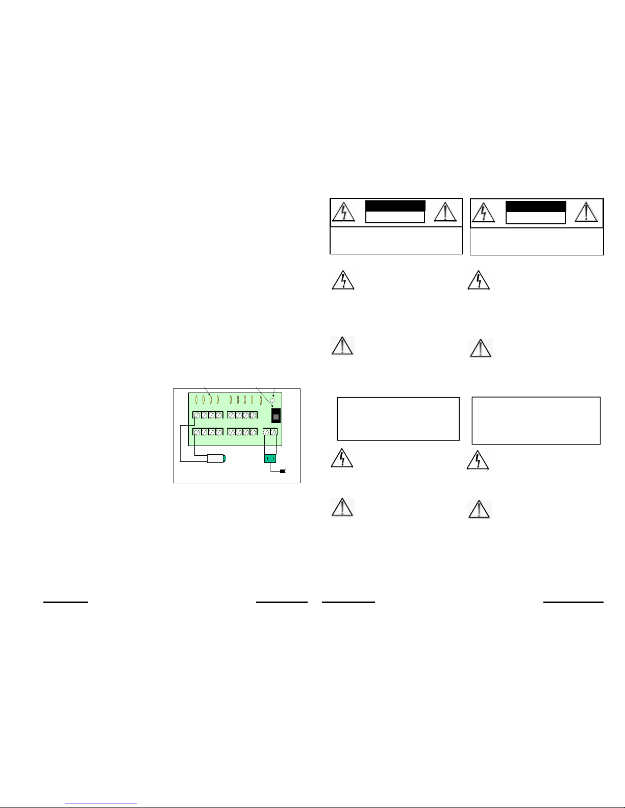
4.TYPICAL INSTALLATION
3935 890 44111 Page 2 © 2003 Bosch Security Systems
COMMON POWER OUTPUTS
FUSED POWER OUTPUTS
AC
ON
OFF
Power LED
1234
1234
5678
5678
ON/OFF
Switch
Self-resetting
Smart Fuses
8 output board shown. 16 output model has
two boards.
Maximum possible cable lengths w
hen
used with the Indoor AutoDome
Gage Wire Distance
18 230 Meters (750 feet)
16 370 Meters (1200 feet)
14 585 Meters (1900 feet)
12 930 Meters (3025 feet)
G3A-PSU1-4, G3A-PSU1-8, G3A-PSU1-16 Installation Instructions
3935 890 44111 Page 3 © 2002 Bosch Security Systems
G3A-PSU1-4, G3A-PSU1-8, G3A-PSU1-16 Installation Instructions
 Loading...