

Bosch FPC-500-2, FPC-500-4, FPC-500-8 Installation Manual
Conventional Fire Panel
FPC-500-2 / FPC-500-4 / FPC-500-8
en Installation Guide


Table of contents
1
Safety Instructions 6
2
System Overview 8
2.1 Operating Levels 12
3
Installation 13
3.1 Scope of Delivery 13
3.2 Installation 13
3.2.1 Inserting the Cable 13
3.2.2 Opening the Housing 14
3.2.3 Installing the Housing 15
3.2.4 Mains Supply 16
3.2.5 Batteries, 24 V Emergency Power Supply 17
3.2.6 Extensions 18
3.3 Wiring 19
3.3.1 Inputs 20
3.3.2 Zones 21
3.3.3 Aux power 23
3.3.4 Notification Appliances 24
3.3.5 Relay Outputs 25
3.3.6 Extensions 26
3.3.7 External power supply 26
3.4 Initial Start-Up 29
3.4.1 Setting the Language 29
3.4.2 Setting the Time and Date 29
4
System Configuration 31
4.1 System Configuration 34
4.1.1 Setting the Date/Time 34
4.1.2 Buzzer Beep 34
4.1.3 EOL Elements 35
4.1.4 Resetting Zones 35
4.1.5 Aux Power 37
4.1.6 Faults 37
4.1.7 Level Code 38
4.1.8 Test Log 39
Conventional Fire Panel Table of Contents | en 3
Bosch Sicherheitssysteme GmbH 2014.06 | 7.0 | F.01U.172.980

4.2 Configuring Delays 39
4.2.1 Deactivating Day Mode 40
4.2.2 Alarm Verification 40
4.2.3 Intermediate Alarm Storage 42
4.2.4 Delay for Mains Fault 44
4.3 Zone Configuration 44
4.4 Configuring Inputs 47
4.4.1 Input 1 48
4.4.2 Input 2 (FPC-500‑8 only) 49
4.5 Configuring Outputs 49
4.5.1 Notification Appliances 49
4.5.2 Alarm Relay 51
4.5.3 OC/Relay Extensions 52
4.6 Displaying the Configuration 53
4.7 Controlling Outputs 54
4.7.1 Notification appliance 1 54
4.7.2 Notification appliance 2 54
4.7.3 Alarm Relay 55
4.7.4 Fault Relay 55
4.7.5 OC/Relay Extension 55
4.7.6 Control all outputs 56
4.8 Resetting To Delivery State 56
5
Fault Diagnosis 58
6
Technical Data 59
6.1 Electrical Data 59
6.1.1 Communication parameters 61
6.2 Mechanical 62
6.3 Environmental Conditions 62
6.4 Information as per EN 54‑4, chapter 7.1 63
6.5 Options with requirements as per EN 54‑2:1997/A1:2006 64
7
Appendix 65
7.1 Brief Overview, Operating Level 1 and 2 65
7.2 Test menu 66
7.3 Brief Overview, Operating Level 3 67
7.4 Default Settings 74
4 en | Table of Contents Conventional Fire Panel
2014.06 | 7.0 | F.01U.172.980 Bosch Sicherheitssysteme GmbH

7.5 Event Memory 76
7.6 Test Memory Messages 78
Index 79
Conventional Fire Panel Table of Contents | en 5
Bosch Sicherheitssysteme GmbH 2014.06 | 7.0 | F.01U.172.980
Safety Instructions
Danger!
The fire panel may only be operated with the housing closed
because of the danger of an electric shock.
Danger!
Only perform installation work when the panel has no voltage.
There is a danger of an electric shock.
!
Caution!
Installation may only be performed by authorized qualified
personnel in order to ensure that the system is not damaged
and operates properly.
Notice!
Note local regulations when connecting to 230 V power
supplies.
Notice!
Please observe the country-specific regulations and guidelines
during planning, installation and programming of the fire panel.
Notice!
In line with EN 54-13 (BOSEC certificate TCC 2 - 977), each
conventional line must be terminated with EOL modules for the
operation of fire detection systems.
The AUX power supply must also be terminated with EOL
modules when using four-wire detectors.
1
6 en | Safety Instructions Conventional Fire Panel
2014.06 | 7.0 | F.01U.172.980 Bosch Sicherheitssysteme GmbH

Notice!
The fire panel has been designed for operation in closed rooms.
Please note the permissible environmental conditions in the
technical specifications.
Conventional Fire Panel Safety Instructions | en 7
Bosch Sicherheitssysteme GmbH 2014.06 | 7.0 | F.01U.172.980
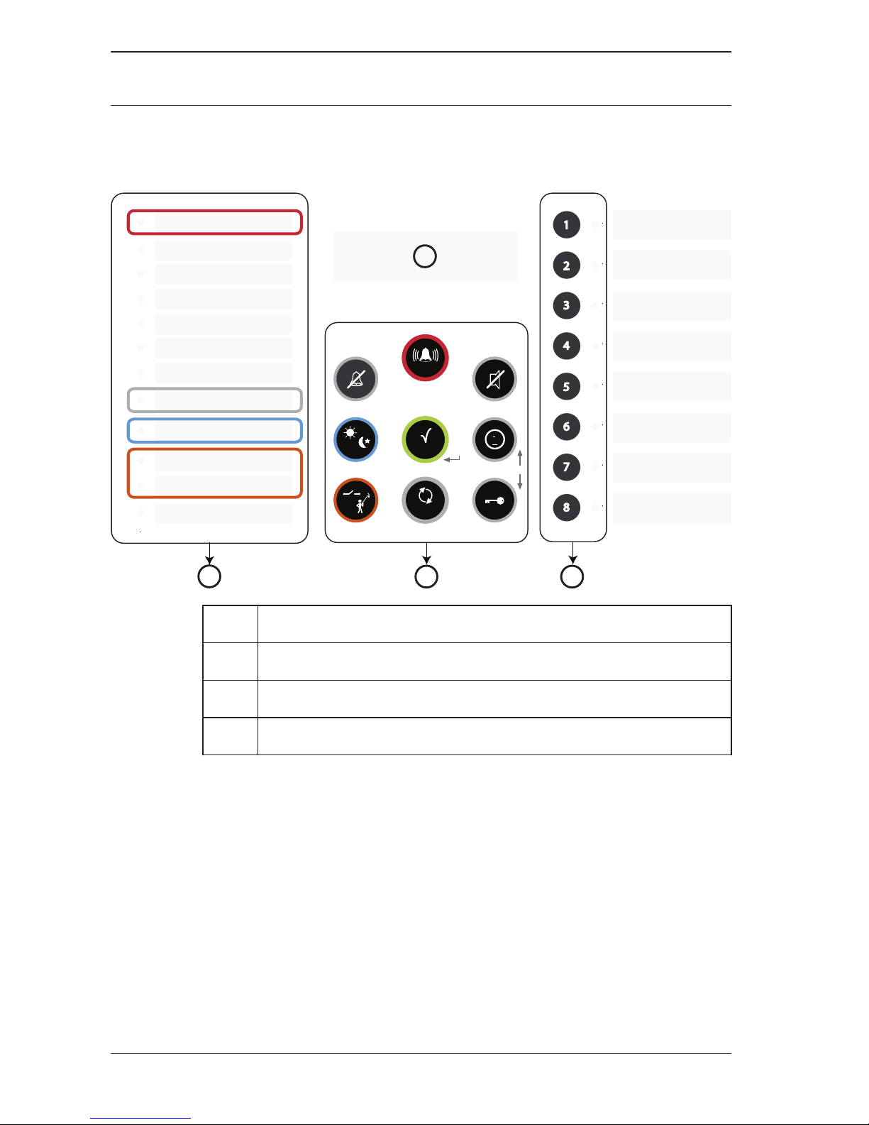
System Overview
1
ESC
8 7 6 5 4 3 2
ACK
i
RESET
EVAC
1
2
3
4
5
6
7
8
P re-Alarm
F ault
System Fault
Earth Fault
Power Fault
NAC Fault / Disabled
Notification Appliance Silent
Day Mode
T est
D isable
Power
A LARM
4
3
1
2
1 LED display
2 LCD display with zone numbers
3 Zone keys and zone status LEDs
4 Operating panel
2
8 en | System Overview Conventional Fire Panel
2014.06 | 7.0 | F.01U.172.980 Bosch Sicherheitssysteme GmbH
FPC-500-2FPC-500-4FPC-500-
8
Inputs
– Zones
– Prog. inputs
2
1
4
1
8
2
Outputs
– Prog. AUX (500 mA)
– Alarm device, 500 mA
each
– Relay
1
2
2
Extensions
– Open collector (20 mA)
– Relay (via OC)
no
1 x 4
2 x 4
LCD, 2 x 16 characters Yes
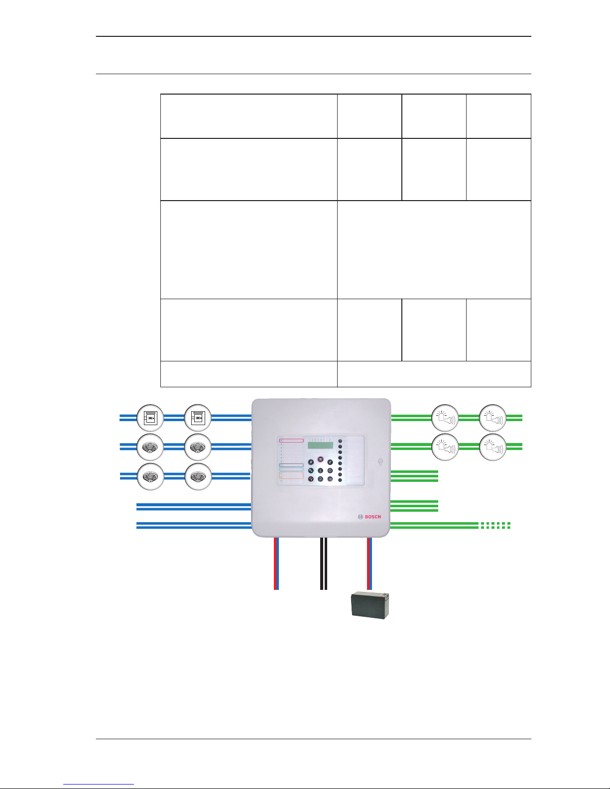
230
VAC
AUX
24 V DC
OC (0, 4, 8)
Z1
.
.
.
Z8
ALARM RLY
FAULT RLY
IN1
IN2
Conventional Fire Panel System Overview | en 9
Bosch Sicherheitssysteme GmbH 2014.06 | 7.0 | F.01U.172.980
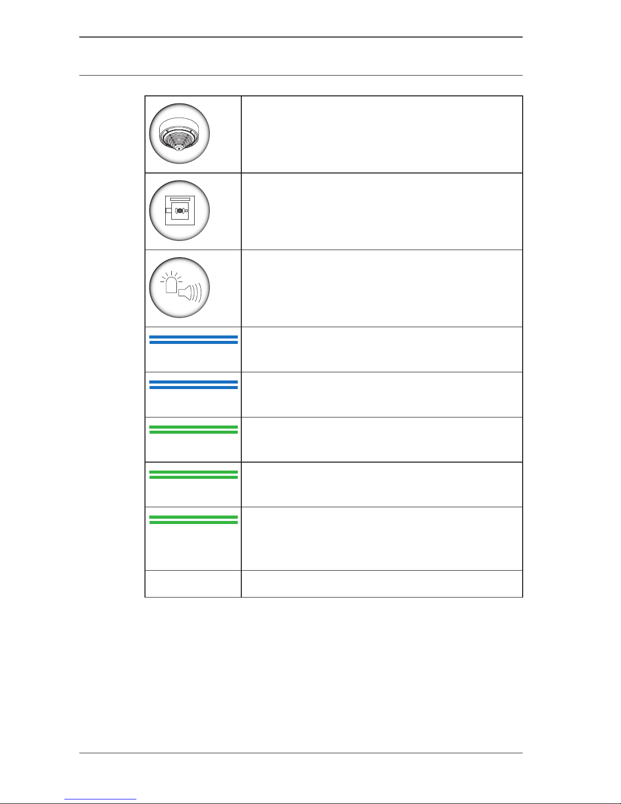
Conventional detectors
Conventional manual call point
Visual or audible notification appliances
Z1 ... Z8
Conventional zones 1 to 8
(max. 2 on FPC-500-2, max. 4 on FPC-500-4)
IN
Inputs (max. 1 on FPC‑500‑2 and FPC‑500‑4,
max. 2 on FPC‑500‑8)
ALARM RLY
Alarm relay
FAULT RLY
Fault relay
OC
Transistor output for extension cards
(0 on FPC‑500‑2, 4 on FPC‑500‑4, 8 on
FPC‑500‑8)
AUX 24 VDC AUX power supply
Features
– Alarm verification: The user is prompted to verify the alarm.
– Intermediate alarm storage: an alarm triggered by an
automatic detector is reset automatically after 20 seconds
(adjustable) by the panel. If there is an additional alarm
within 10 minutes in this zone, the notification appliances
are enabled. Otherwise the pre-alarm is reset automatically.
– Dual-zone dependency on neighboring zones.
10 en | System Overview Conventional Fire Panel
2014.06 | 7.0 | F.01U.172.980 Bosch Sicherheitssysteme GmbH

– Dual-detector dependency for detectors in a zone.
– Alarm counter for 999 alarms.
– Event memory for 1000 entries.
– Three operating levels, two of them protected with freely
selected code.
– Up to 8 monitored detector zones depending on panel
version.
– Up to 2 monitored inputs available depending on panel
version.
– One alarm and one fault relay.
– Up to 8 additional transistor or relay outputs, freely
programmable, depending on panel version.
– Quick and easy programming using the keypad and LCD
display.
– Easy operation for the end user.
– Two monitored notification appliance outputs.
– EN 54-13 (BOSEC certificate TCC 2 - 977) compliant system
by using EOL modules.
– Power supply via power supply unit with thermal fuse.
– Emergency power supply using batteries, up to 7.2 Ah,
reverse polarity protected.
– Removable quick guide for the user on the panel.
Conventional Fire Panel
System Overview | en 11
Bosch Sicherheitssysteme GmbH 2014.06 | 7.0 | F.01U.172.980

Operating Levels
This fire panel has three operating levels. You can only perform
certain actions depending on operating level.
Level 1 – Display information
– Read out event memory
– Display faults and deactivations
– Perform display test
Level 2 – Change language and time/date
– Switch key tones on/off
– Put zones in test mode and take zones out of
test mode
– Switch off/on zones, notification appliances,
relay and transistor outputs
– Trigger evacuations
– Reset panel
– Switch between day/night mode
– All actions of level 1
Level 3 – All settings for installing and programming the
system.
Code inputs are necessary for accessing level 2 and 3.
2.1
12 en | System Overview Conventional Fire Panel
2014.06 | 7.0 | F.01U.172.980 Bosch Sicherheitssysteme GmbH
Installation
Scope of Delivery
The fire panel packaging contains the following components:
– Fire panelFPC‑500‑2/FPC‑500‑4/FPC‑500‑8
– EOL resistors for zones and inputs
– Battery cable set
– Cable ties for strain relief on power supply feeder
– Labeling strips for zones and LEDs
– Quick Installation Guide
– Quick Operation Guide
– CD
– Two plastic foam blocks for securing the batteries
Installation
Notice!
Install the fire panel in a location easily accessible to
emergency response teams (e.g. fire department).
Note permissible environmental conditions.
Install the fire panel at a height above the ground that permits
convenient operation by the user and easy reading of the LCD
display.
Inserting the Cable
Route the necessary cables for zones, inputs and outputs, as
well as the power supply, etc., and carefully punch out the cable
entries needed for this.
!
Warning!
Electrostatic discharge (ESD)! Electronic components could
become damaged. Ground yourself using a wrist strap or take
other suitable measures.
3
3.1
3.2
3.2.1
Conventional Fire Panel Installation | en 13
Bosch Sicherheitssysteme GmbH 2014.06 | 7.0 | F.01U.172.980
Remove the PC board if necessary. This is secured in the
housing with a grounding screw and snap-fit hook.
For cable entry on the upper side of the housing, use the preformed round holes. For more stable insertion, M 20 x 1.5 screw
joints (PG13.5) can be used.
The cable entries on the rear are intended for direct cable entry
of flush mounted cables.
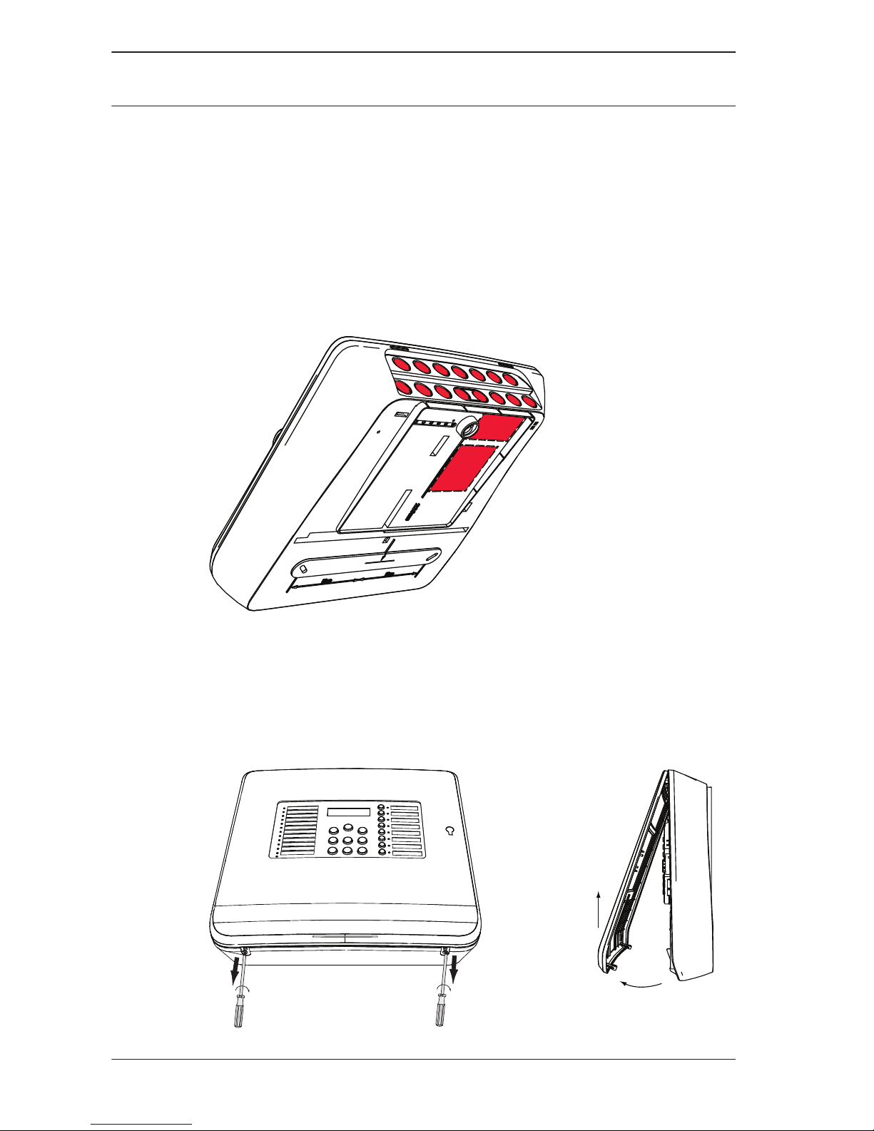
Opening the Housing
Remove the cover of the fire panel. Loosen both screws on the
underside of the housing, lift up the cover approx. 20° and
remove it.
3.2.2
14 en | Installation Conventional Fire Panel
2014.06 | 7.0 | F.01U.172.980 Bosch Sicherheitssysteme GmbH
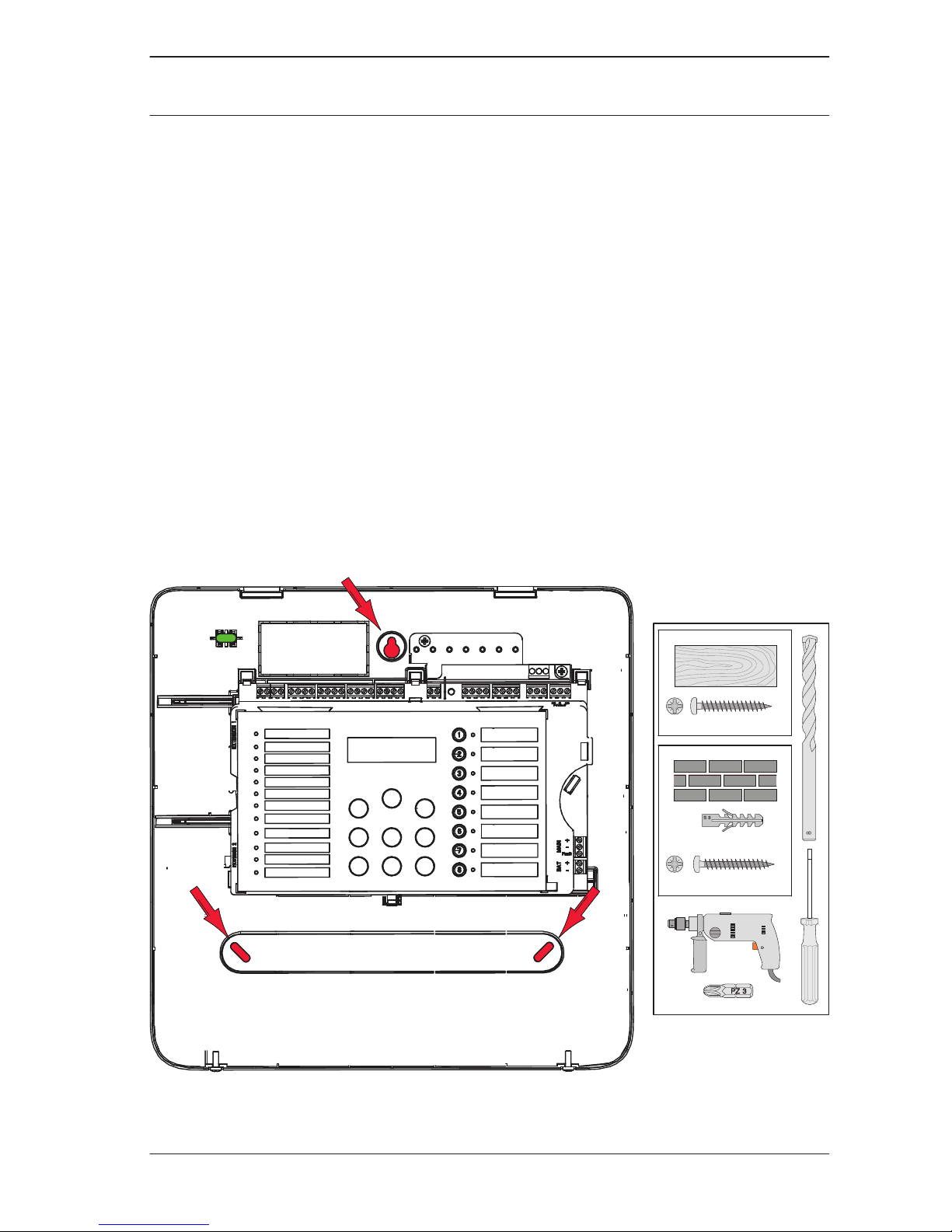
Installing the Housing
Use the panel housing to draw drill holes at the desired location
on the wall (arrows in figure below). As an option, you can use
the mounting dimensions indicated on the back of the housing.
Ensure that the housing is aligned horizontally and draw on the
holes using the built-in spirit level in the upper left corner. The
dimensions can be taken from the drilling jib on the rear of the
housing. Drill the holes.
Guide the cables routed under plaster through the punched out
cable ducts on the rear of the housing into the housing. Mount
the housing to the wall using screws. Make sure that cables are
not pinched.
Then guide the cables routed on plaster through the cable
entries to the upper side of the housing.
3x
( 8 x 40 mm)
3x
6 x 50 mmPZ3
S8
3x
6 x 50 mmPZ3
8mm
PZ3
3x
( 8 x 40 mm)
3x
6 x 50 mmPZ3
S8
3x
6 x 50 mmPZ3
8mm
PZ3
3.2.3
Conventional Fire Panel Installation | en 15
Bosch Sicherheitssysteme GmbH 2014.06 | 7.0 | F.01U.172.980
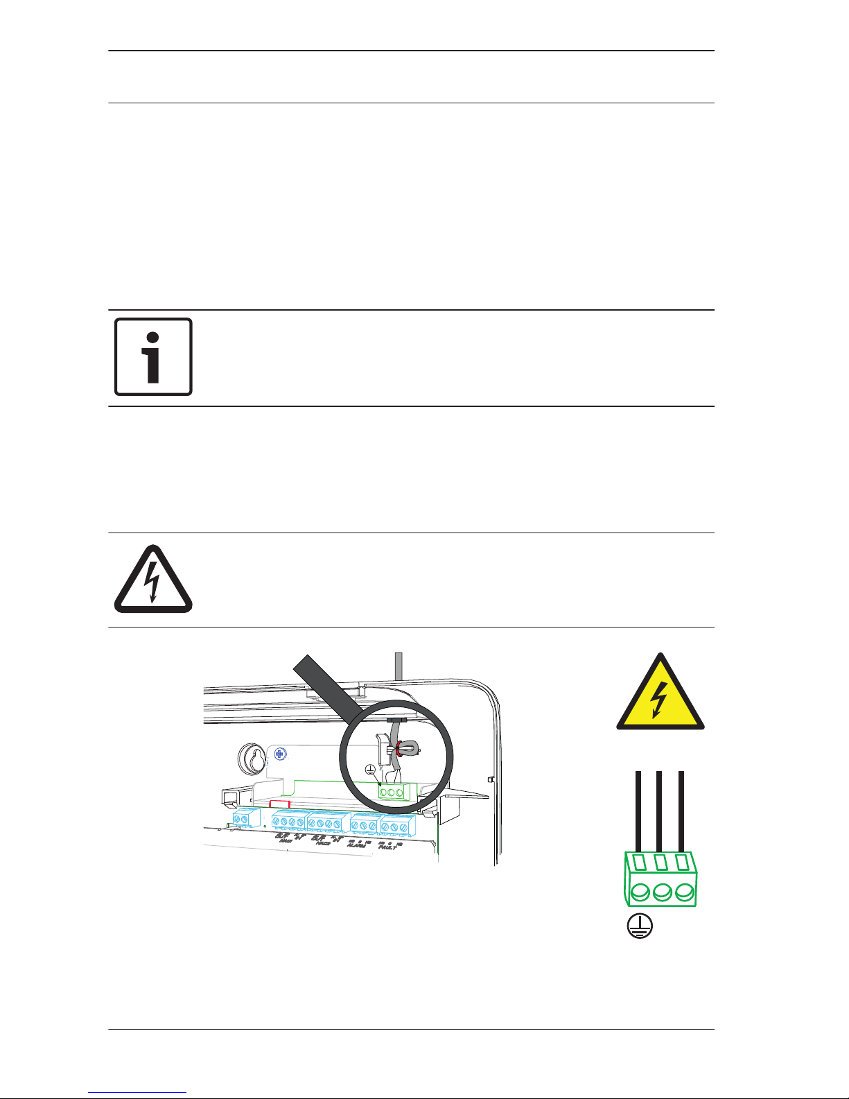
Mains Supply
The fire panel requires a 230 V mains supply for the power
supply. Route the power supply so that the line does not cross
or touch the signal line.
Use the left M 20 x 1.5 screw joint (PG13.5) on the upper side
of the panel for the 230 V mains supply.
Notice!
Note local regulations when connecting to 230 V power
supplies.
Wire up the 230 V power supply to the screw clamp provided on
the power supply unit board. Use a cable tie to ensure strain
relief of the power supply feeder in the housing above the
power supply unit.
Danger!
Only perform installation work when the panel has no voltage.
There is a danger of an electric shock.
N L
230 VAC
50 - 60 Hz
3.2.4
16 en | Installation Conventional Fire Panel
2014.06 | 7.0 | F.01U.172.980 Bosch Sicherheitssysteme GmbH
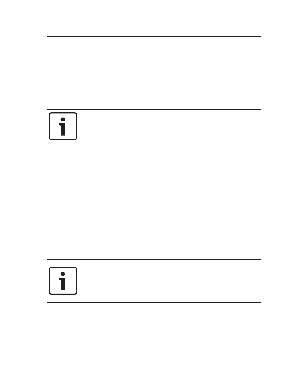
Batteries, 24 V Emergency Power Supply
You can use two 12 V batteries with maximum 7.2 Ah each in the
housing as emergency power supply.
The batteries are connected in series. If the mains power fails,
they are used to ensure interruption-free power supply of the
fire panel and the components fed by them.
Notice!
The fire panel can also only be started with the batteries if the
power supply is disconnected.
After you have placed the batteries in the housing, secure them
using the plastic foam blocks provided.
Position the plastic foam blocks in between the top of the
batteries and the housing.
There are different emergency current back-up times depending
on the battery capacity used and the current consumption of the
components connected to the panel. You can calculate this
using the battery calculator included on the CD.
After troubleshooting a mains fault and operating the fire panel
via emergency current, the power supply unit switches back to
mains operation automatically. The batteries are charged again
automatically.
Notice!
Note the polarity of the batteries.
If the batteries are connected with the polarity reversed, the
thermal fuse on the main board of the fire panel reacts.
3.2.5
Conventional Fire Panel Installation | en 17
Bosch Sicherheitssysteme GmbH 2014.06 | 7.0 | F.01U.172.980
BAT
- +
Secure the batteries with the plastic foam blocks provided so
that they cannot move.
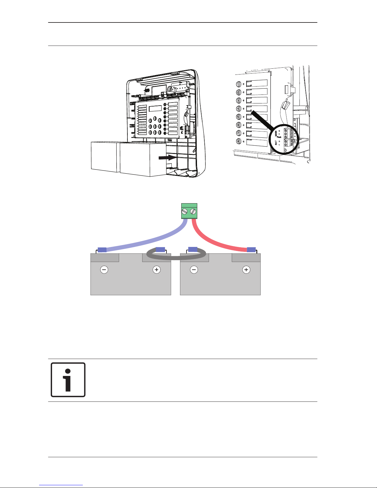
Extensions
Notice!
Note that the maximum line resistance for transistor outputs is
22.5 Ohm.
The extensions are connected to the left side of the main board.
Simply connect the board to the plugs. Make sure that the plug
engages correctly.
3.2.6
18 en | Installation Conventional Fire Panel
2014.06 | 7.0 | F.01U.172.980 Bosch Sicherheitssysteme GmbH
There is a groove on the top of the extensions. Make sure that
the board has been correctly installed.
Notice!
A maximum of two extensions can be connected:
FPC-500‑2: No extension can be connected
FPC-500‑4: One extension can be connected
FPC-500‑8: Two extensions can be connected
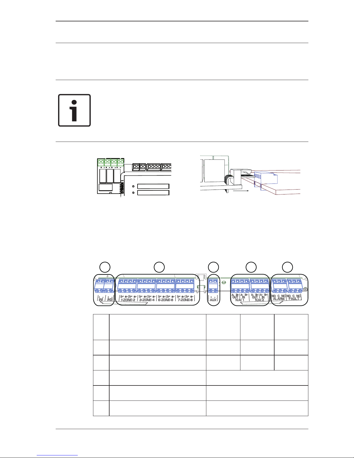
Wiring
External components such as zones, notification appliances,
inputs, etc. are wired to screw terminals attached to the upper
side of the board.
1 2 3 4 5
No.Meaning FPC‑500-2FPC‑500-4FPC‑500
-8
1 Inputs 1 1 2
2 Zones 2 4 8
3 Aux power supply 1
4 Notification appliance 2
5 Alarm and fault relay 1/1
3.3
Conventional Fire Panel Installation | en 19
Bosch Sicherheitssysteme GmbH 2014.06 | 7.0 | F.01U.172.980
Notice!
The screw terminals are designed for a cable diameter of
0.8 mm and for cable cross sections of up to 1.5 mm2.
The fire panel is designed for unshielded cable. If you do use
shielded cable, only connect the cable shielding to the earth
bar on one side above the power supply unit.
Terminal resistances
The zones of the fire panels must be terminated. Use either
resistors or in case of EN 54-13 (BOSEC certificate TCC 2 - 977)
the EOL modules.
Notice!
Only use resistors with a maximum 1% tolerance.
The 3.9 kOhm resistors are supplied.
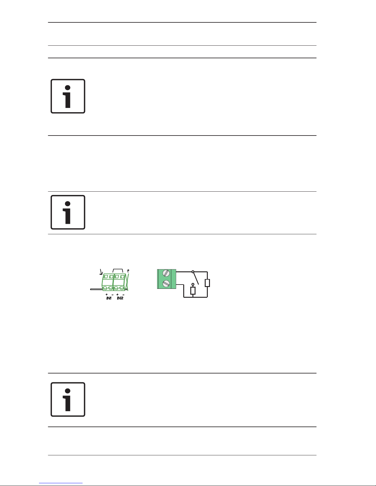
Inputs
+ -
IN1
820Ω ± 5%
3,9kΩ
The fire panel offers two control inputs. You can assign different
functions to these depending on programming (see Configuring
Inputs, page 47).
The connection terminals IN1 and IN2 are available.
Notice!
Note that the maximum line resistance for inputs is 22.5 ohm.
Use 820 Ohm ±5% resistors for the alarm resistance (not
included in scope of delivery).
3.3.1
20 en | Installation Conventional Fire Panel
2014.06 | 7.0 | F.01U.172.980 Bosch Sicherheitssysteme GmbH
Notice!
Only use buttons (no locking element) if you have programmed
inputs as Drill/Evacuate, Silence, or Reset Panel.
Access levels as per EN 54‑2 must be observed.
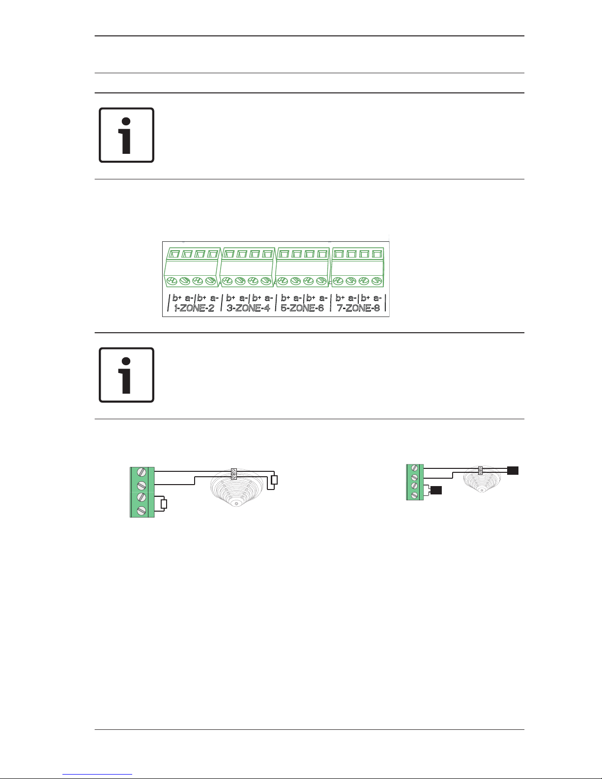
Zones
Notice!
Do not connect the zone- with any power+ like for example:
AUX power, external power supply or batteries for emergency
power supply.
b+ a-|b+ a-
1-ZONE-2
3,9kΩ
a-
b+
3,9kΩ
b+ a-|b+ a-
1-ZONE-2
EOL
EOL
a-
b+
EN 54‑13 (BOSEC
certificate TCC 2 - 977)
Each zone must be completed with a terminal element.
You can either use a 3.9 kΩ ± 1% resistor or EOL modules for an
EN 54-13 (BOSEC certificate TCC 2 - 977) compliant
termination.
Unused zones must also be terminated with a terminal element.
Mixing different terminal elements is not allowed.
3.3.2
Conventional Fire Panel Installation | en 21
Bosch Sicherheitssysteme GmbH 2014.06 | 7.0 | F.01U.172.980
Notice!
Note that the maximum line resistance for conventional zones is
22.5 Ohm.
The voltage of the zones is 20 VDC ±1 V.
The maximum current of the zones is 100 mA ±5 mA.
Notice!
Observe local regulations for the maximum number of detectors
in a zone.
When using the FLM-320-EOL4W Module, use the battery
calculator included on the CD.
Notice!
The last zone of the fire panel supports the use of 4-wire
detectors.
The fire panel does not support dual-detector dependency with
4-wire detectors.
Please use permissible external power supply units depending
on power consumption.
Notice!
Activating a manual call point in a zone programmed as "No
Delay" triggers an immediate alarm.
Notice!
Only use manual call points in zones which are programmed as
No Delay.
22 en | Installation Conventional Fire Panel
2014.06 | 7.0 | F.01U.172.980 Bosch Sicherheitssysteme GmbH
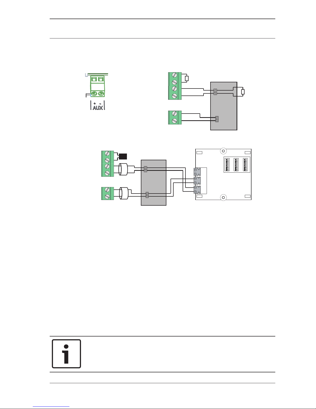
Aux power
b+ a-|b+ a-
7-ZONE-8
3,9kΩ
a-
b+
3,9kΩ
+ -
AUX
+
-
4W
Non-EN54-13
b+ a-|b+ a-
7-ZONE-8
+ -
AUX
+
-
POWER CONV
Shield +U 0V b+ a-
R
V
P
FLM-320-EOL4W
EOL
4W
a-
b+
EN54-13 (BOSEC certificate TCC 2 - 977)
The fire panel allows you to use 4-wire (4W) elements on the
last zone. These must be supplied with power by the auxiliary
power supply or an external power source. Both the zone and
the auxiliary power must be terminated by a terminal element.
For EN 54-13 (BOSEC certificate TCC 2 - 977) compliant
connection of 4‑wire elements, the AUX and zone lines must be
routed in separate cables.
You can either use a 3.9 kΩ ±1% resistor or EOL modules for
EN 54-13 (BOSEC certificate TCC 2 - 977) compliant
termination.
Program the reset behavior of the auxiliary power as described
in Aux Power, page 37.
Notice!
Note that the maximum line resistance for the auxiliary power is
22.5 Ohm.
3.3.3
Conventional Fire Panel Installation | en 23
Bosch Sicherheitssysteme GmbH 2014.06 | 7.0 | F.01U.172.980
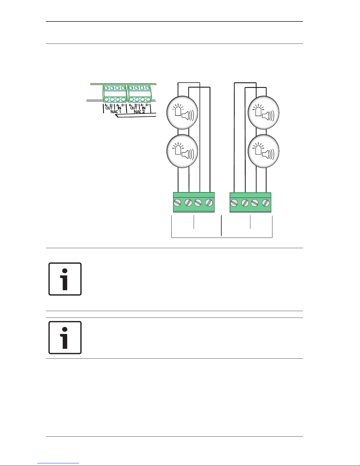
Notification Appliances
NAC1
A- B+
OUT IN
A- B+
NAC2
A- B+ A- B+
INOUT
Notice!
Each notification appliance output provides connected
notification appliances with a maximum current of 500 mA at
24 VDC. The permissible voltage range of the output is 21–
29 VDC.
Notice!
Note that the maximum line resistance for notification
appliances is 22.5 Ohm.
The fire panel offers you two notification appliance circuit lines
that can be used to activate the audible notification appliances
and visual notification appliances. When there is a fire alarm, the
notification appliance circuit lines are activated depending on
programming.
3.3.4
24 en | Installation Conventional Fire Panel
2014.06 | 7.0 | F.01U.172.980 Bosch Sicherheitssysteme GmbH
Notice!
Connect the notification appliances to the terminals NAC1
and/or NAC2. This connection is EN 54‑13 (BOSEC certificate
TCC 2 - 977) compliant.
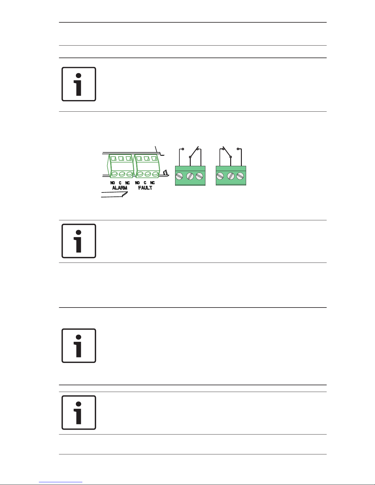
Relay Outputs
NO C NC
ALARM
NO C NC
FAULT
Notice!
The fault relay is activated in a normal state. It is opened in the
event of a fault.
The fire panel has two relay outputs. The relays work as
potential-free change-over contacts.
The alarm relay is activated by every fire alarm.
Notice!
A transmission device must be installed in the immediate
vicinity (without a space) of the FPC‑500‑x.
The connecting line between the fire panel and the
transmission device must not be exposed, as it is not
monitored.
Notice!
Both relay outputs "ALARM" and "FAULT" can switch a
maximum of 1 A @ 30 VDC each.
3.3.5
Conventional Fire Panel Installation | en 25
Bosch Sicherheitssysteme GmbH 2014.06 | 7.0 | F.01U.172.980
 Loading...