

Bosch F.01U.252.699 User Manual

NurseCall Main Unit
F.01U.252.699 | V1.1 | 2012.01
en User Manual


NurseCall Main Unit Table of Contents | en 3
Bosch Security Systems User Manual F.01U.252.699 | V1.1 | 2012.01
Table of Contents
1 Safety instructions 6
1.1 Importance of safety instructions 6
1.2 Disregarding safety rules 6
1.3 Environmental conditions 6
1.4 General safety instructions 6
1.4.1 Observation and information 7
2 Description 8
2.1 General description 8
2.1.1 Top view 8
2.1.2 Bottom view 9
2.1.3 Front view 10
2.1.4 Rear view 10
2.2 Detailed description 11
2.2.1 Loudspeaker 11
2.2.2 Display 11
2.2.3 Keyboard 11
2.2.4 RS-232 interface 13
2.2.5 RS-485 interface 14
2.2.6 Antenna 14
3 Installation 15
3.1 Unpacking 15
3.1.1 List of contents 15
3.2 Installation 16
3.2.1 Generalities 16
3.2.2 Installation on a piece of furniture 16
3.2.3 Wall installation 16
3.2.4 Installing the antenna 16
3.2.5 Connecting to the mains 17
3.2.6 Connecting the RS-232 17
3.2.7 Setting the jumpers on the communication board 18
3.2.8 Connecting the RS-485 19
3.2.9 Setting the 100 Ohm termination jumper 20
4Programming 21
4.1 Generalities 21
4.1.1 Programming with the keyboard 21
4.1.2 Programming with the NPS software 22
4.1.3 Exit the programming mode and cancel entries 22
4.1.4 Key not allowed 22
4.1.5 Locking and unlocking the keyboard 22
4.1.6 Programming time-out 22
4.2 First use 22
4.2.1 List of original factory settings 23
4.2.2 Language 24

4 en | Table of Contents NurseCall Main Unit
F.01U.252.699 | V1.1 | 2012.01 User Manual Bosch Security Systems
4.2.3 Locating mode 24
4.2.4 Display mode 24
4.3 Parameters 25
4.3.1 Access to parameters 25
4.3.2 List of parameters 25
4.3.3 Programming the unit language 25
4.3.4 Date and time setting 26
4.3.5 RS-232 output setting 27
4.3.6 Local acknowledgement setting 31
4.3.7 Output relay setting 31
4.3.8 Accompany mode 32
4.3.9 Radio noise check 32
4.3.10 Tracking function 33
4.3.11 Dementia criterion 33
4.3.12 Assistance alarm from S35Q, S37Q and S37L transmitters 33
4.4 Special settings 34
4.4.1 Displaying firmware version 34
4.4.2 Resetting all the parameters 34
4.4.3 Assistance and fire priority 35
4.4.4 Assistance and fire non priority 35
4.4.5 Special texts in German 35
4.4.6 Standard texts in German 35
4.4.7 Standard NurseCall selection 35
4.4.8 Universal NurseCall selection 36
4.4.9 Maximum number of alarm transmitters 37
4.4.10 Maximum number of acknowledgement transmitters 37
4.4.11 Maximum number of events buffered 37
4.4.12 Disabling the daily messages check 37
4.4.13 RS232 message setting 37
4.5 Transmitters 38
4.5.1 Starting programming 38
4.5.2 Programming an alarm transmitter 38
4.5.3 Checking an alarm transmitter 39
4.5.4 Erasing an alarm transmitter 40
4.5.5 Programming an acknowledgement transmitter 40
4.5.6 Checking an acknowledgement transmitter 41
4.5.7 Erasing an acknowledgment transmitter 41
4.5.8 Erasing all acknowledgement transmitters 42
5Operation 43
5.1 Adjusting the loudspeaker volume 43
5.2 Consulting the alarm or event buffer 43
5.2.1 Switching between alarm and event buffers indication 44
5.2.2 Display indications 44
5.2.3 Local acknowledgement 45
5.2.4 Disconnecting a Relay Unit 45
6 Troubleshooting and error messages 46
6.1 "Radio in use" message 46

NurseCall Main Unit Table of Contents | en 5
Bosch Security Systems User Manual F.01U.252.699 | V1.1 | 2012.01
6.2 "Alarm Transmitter NOT stored" message 46
6.3 "Alarm Transmitter already stored" message 46
6.4 "Ack. Transmitter NOT stored" message 46
6.5 "Ack. Transmitter already stored" message 46
6.6 The green button does not work 46
7 Maintenance 47
7.1 Checking the system 47
7.2 Monitoring the power supply 47
7.3 Monitoring the backup battery 47
7.4 Cleaning 48
7.5 Parts replacement 48
7.5.1 Disassembling the unit 48
7.5.2 Backup battery replacing 49
8Disposal 50
8.1 Disassembly 50
8.2 Returning to the manufacturer 50
8.3 Materials 50
8.4 Battery 50
A Appendix 51
A.1 Electrical specifications 51
A.2 Dimensions and weight 51
A.3 Environmental conditions 51
A.4 List of criteria 52
A.5 Paging systems specifications 53
A.5.1 ESPA 4.4.4. protocol 53
A.5.2 POCSAG protocol 55
A.5.3 DeTeWe protocol 56
A.5.4 Medicall 800 protocol 57
A.6 DECT phone system specifications 58
A.6.1 Multitone DECT systems with P318 interface 58
A.7 Connectors 59
A.7.1 LINE socket (unit bottom) 59
A.7.2 Power socket (unit bottom) 59
A.7.3 RS-232 socket (unit rear) 59
A.7.4 RS-485 socket (unit rear) 59
6 en | Safety instructions NurseCall Main Unit
F.01U.252.699 | V1.1 | 2012.01 User Manual Bosch Security Systems
1 Safety instructions
1.1 Importance of safety instructions
Each safety and protection instruction in this manual must be adhered to in order to avoid
personnel injuries, property damages or environmental pollution.
In a similar manner, the legal bylaws, the measures in prevention of accidents and for the
protection of the environment, as well as the recognized technical rules aiming at appropriate
and safe working conditions which as applied in the country and at the place of use of the
NurseCall Main Unit must be adhered to.
1.2 Disregarding safety rules
Disregarding the safety rules, as well as existing legal and technical regulations, may lead to
accidents, to property damages or to environmental pollution.
1.3 Environmental conditions
Install the NurseCall Main Unit in a dry place, away from any source of heat.
1.4 General safety instructions
NOTICE!
The user and installer should read and understand this chapter before any intervention on the
NurseCall Main Unit.
NOTICE!
The NurseCall Main Unit must not be located near a water tap or any other source of water.
The electrical safety of the unit is only guaranteed if the electrical installation is conform to
the national regulation and if this installation works properly.
The NurseCall Main Unit may not be used in buildings prone to fire and explosion hazards.
NOTICE!
The NurseCall Main Unit may not be used under exposure to the direct sunlight, to heat, to
dust or to an excessive humidity (only use the equipment in a clean environment).
CAUTION!
Interferences
Avoid immediate proximity to other electric devices such as a television.
DANGER!
Electrocution
During maintenance operations, when the NurseCall Main Unit is powered and its casing is
removed, it may not be left unattended.
CAUTION!
The NurseCall Main Unit may only be connected to the electrical sources as described in
Section A.1 Electrical specifications, page 51.
NurseCall Main Unit Safety instructions | en 7
Bosch Security Systems User Manual F.01U.252.699 | V1.1 | 2012.01
1.4.1 Observation and information
In case of defective operation or any other technical incident for which no remedy is
described in this manual, please contact immediately your local representative.
CAUTION!
Maintenance and repairs may only be performed in conformance with the instructions and by
authorized technical personnel only.
The sole possession of the user manual does not allow the personnel to perform any kind of
repair on the NurseCall Main Unit.
Take into account all the warnings and follow all the instructions displayed on the NurseCall
Main Unit and those which are printed in the documentation.
Never try to use replacement pieces other than those authorized by the manufacturer of the
NurseCall Main Unit.
CAUTION!
It is mandatory to use the products specified in the present user manual to clean the
NurseCall Main Unit. If you plan to use another product, only do so after having obtained the
authorization of the manufacturer.
DANGER!
The NurseCall Main Unit contains highly sensitive electronic components. It should be opened
only in an ESD protected environment with respect to the following precautions:
1. Discharge yourself from electrostatic loads by touching a grounded conductive surface
before opening the unit.
2. Avoid touching conductive parts inside the unit if not absolutely necessary.
CAUTION!
Never let any liquid enter the system. In case of liquid spill inside the NurseCall Main Unit, act
immediately as follows:
1. Switch off the unit using the main switch under the casing.
2. Unplug the power supply adaptor.
3. Dry up the unit.
4. Clean the unit.
5. Check that the unit switches on correctly.
8 en | Description NurseCall Main Unit
F.01U.252.699 | V1.1 | 2012.01 User Manual Bosch Security Systems
2 Description
2.1 General description
2.1.1 Top view
1. Loudspeaker.
See Section 2.2.1 Loudspeaker, page 11.
2. Display.
See Section 2.2.2 Display, page 11.
3. Keyboard, under the cover.
See Section 2.2.3 Keyboard, page 11.
4. LED Indicator
5. Yellow button
Used to view more details about the event or alarm currently displayed (date and time,
position, etc...).
6. Green button
Used to acknowledge an alarm locally, see Section 5.2.3 Local acknowledgement, page 45.
7. Red button with light
This button is not used. Pressing the button does not activate a function.
The light blinks red during an alarm.
2
1
3
7654
NurseCall Main Unit Description | en 9
Bosch Security Systems User Manual F.01U.252.699 | V1.1 | 2012.01
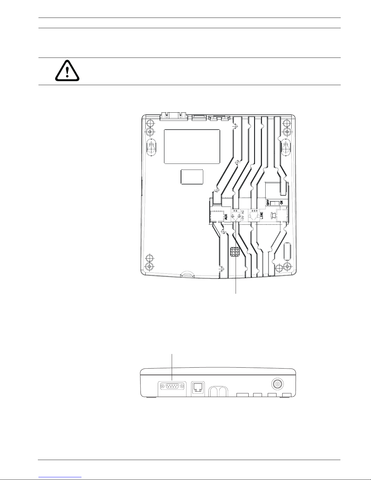
2.1.2 Bottom view
1. Identification label.
2. Cable channels.
3. Wall mounting holes (distance between holes, 157 mm).
See Section 3.2.3 Wall installation, page 16 for a detailed description.
4. ON/OFF switch.
5. LINE socket, used for firmware update.
See Section A.7.1 LINE socket (unit bottom), page 59 for wiring.
6. 10V AC socket.
See Section A.7.2 Power socket (unit bottom), page 59 for wiring.
4
3
65
12
3

10 en | Description NurseCall Main Unit
F.01U.252.699 | V1.1 | 2012.01 User Manual Bosch Security Systems
2.1.3 Front view
1. LED Indicator
2.1.4 Rear view
1. RS-232 connector
See Section A.7.3 RS-232 socket (unit rear), page 59 for wiring.
2. RS-485 connector
See Section A.7.4 RS-485 socket (unit rear), page 59 for wiring.
3. Antenna connector
Status LED
Standby mode (normal operation) Green (permanent)
Backup battery low Green (blinking)
Power supply disconnected Green (flashing)
Help, assistance or fire Red (blinking)
Programming mode Orange (blinking)
1
12 3
NurseCall Main Unit Description | en 11
Bosch Security Systems User Manual F.01U.252.699 | V1.1 | 2012.01
2.2 Detailed description
2.2.1 Loudspeaker
When one of the following alarms or messages is received by the NurseCall Main Unit, the
internal loudspeaker is activated until acknowledgement.
2.2.2 Display
The NurseCall Main Unit is equipped with a 2 x 20 characters display that guides the operator
during the programming. During normal operation, alarms and messages are displayed.
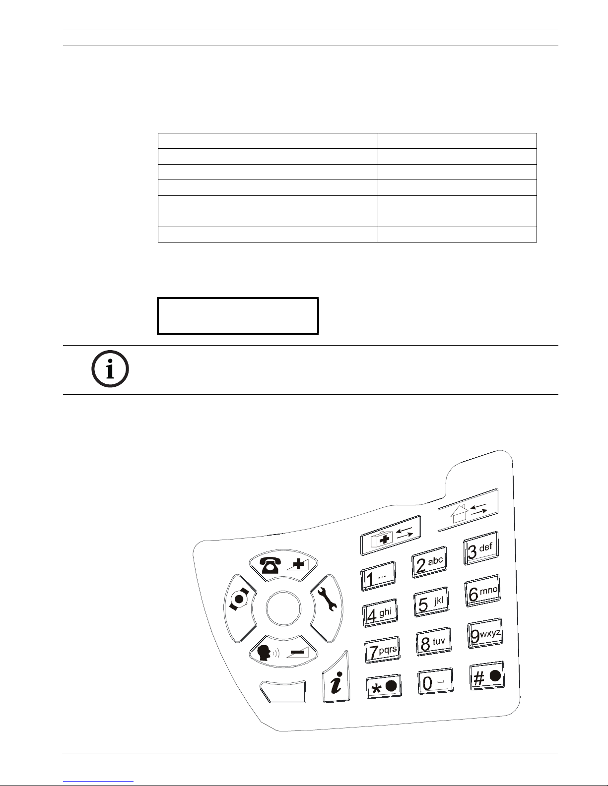
2.2.3 Keyboard
The keyboard has 21 alphanumeric keys. They are used to program the NurseCall Main Unit or
during normal operation.
Status Loudspeaker
Power supply disconnected Dual-tone beep every minute
Call for help, reserve call, technical call 4 second interval, one tone
Error message 15 second interval, one tone
Disconnection of a relay unit from RS485-bus 1 minute interval, one tone
Call for assistance / fire alarm Continuously dual-tone beep
Local acknowledgement Short beep
NurseCall Main Unit
V2.01 BN111.240.00A
NOTICE!
This user manual is written for the unit language English USA. Certain displays may differ for
the unit language English UK.
P
T
C
OK
OFF
ON
12 en | Description NurseCall Main Unit
F.01U.252.699 | V1.1 | 2012.01 User Manual Bosch Security Systems
Keys Programming Mode Normal Operation
Access to parameters programming.
See Section 4.3 Parameters, page 25.
Not used.
Access to transmitters programming.
See Section 4.5 Transmitters, page 38.
Not used.
Scroll up to the next parameter. Increase the volume of the loudspeaker.
See Section 5.1 Adjusting the loudspeaker
volume, page 43.
Scroll down to the next parameter. Decrease the volume of the loudspeaker.
See Section 5.1 Adjusting the loudspeaker
volume, page 43.
Set a parameter value to OFF or to go to the
previous programming field.
Scroll down to the previous alarm/event.
Set a parameter value to ON or to go to the next
programming field.
Scroll up to the next alarm/event.
Confirm a value or a command. Not used.
Cancel an entry or a command.
Quit the programming mode.
Not used.
Check the value of a parameter or a transmitter. Check the status of the backup battery.
See Section 7.3 Monitoring the backup
battery, page 47.
Not used. Not used.
NPS programming function. See
Section 4.1.2 Programming with the NPS software,
page 22.
Not used.
to
Enter a value. Not used.
Erase all programmed acknowledgement
transmitters during a specific procedure.
See Section 4.5.8 Erasing all acknowledgement
transmitters, page 42.
Not used.
Disable the beep codes and delete the POS
indication.
See Section 4.3.5 RS-232 output setting, page 27
and Section Example of programming, Page 28.
Not used.
Enter a value or to set the default values.
See Section 4.3.5 RS-232 output setting, page 27.
Launch the event/alarm display mode.
then
No effect. Lock and unlock the keyboard.

NurseCall Main Unit Description | en 13
Bosch Security Systems User Manual F.01U.252.699 | V1.1 | 2012.01
2.2.4 RS-232 interface
A 9-pole SUB-D connector at the rear of the housing can be used for connection to
–a printer
– a paging system
– a DECT phone system
– a PC with Alarm Management Software.
For the hardware configuration of this interface, see Section 3.2.6 Connecting the RS-232,
page 17.
For the programming of this interface, see Section 4.3.5 RS-232 output setting, page 27.
For the wiring of the connector, see Section A.7.3 RS-232 socket (unit rear), page 59.
Connection to a printer
To protocol all events, a printer with serial connection (RS-232 Interface) and endless paper
should be used. Printers with a parallel port can be used together with an intermediate serial
- parallel converter.
Characteristics
– Data rate: 9600 Bauds.
– Transmission: asynchronous
– 10 bit-structure (1 start bit, 8 data bits without parity, 1 stop bit).
The operating status of the printer cannot be tested (switched on/off, paper status).
An RS-232 printer is mandatory.
Connection to a paging system
The NurseCall system uses several protocols: standard ESPA 4.4.4. with RPE670/i-page,
POCSAG, DeTeWe and Medicall 800.
See Section A.5 Paging systems specifications, page 53 for more information about these
protocols.
Connection to a DECT phone system
The NurseCall system can transfer the received alarms to DECT handsets Multitone CH60 or
CH70.
See Section A.6 DECT phone system specifications, page 58 for more information about
this system.
Connection to a PC using an Alarm Management Software
At connection / disconnection of a PC using an Alarm Management Software, events are
generated. The loudspeaker is disabled during the connection.
NOTICE!
The paper printout corresponds to the indication at the display of the NurseCall Main Unit.
NOTICE!
Alarms/messages arriving in the alarm buffer are repeated every 3 minutes until
acknowledgement. A technical failure, for example a power outage, is treated as an event. No
acknowledgement is therefore necessary. See Section 5.2 Consulting the alarm or event buffer,
Page 43.
14 en | Description NurseCall Main Unit
F.01U.252.699 | V1.1 | 2012.01 User Manual Bosch Security Systems
2.2.5 RS-485 interface
One NurseCall Main Unit and up to 32 NurseCall Relay Units can be connected by a RS-485
bus. The bus must be connected to pins 2 and 5 of the RS-485 socket.
For connector wiring, see Section A.7.4 RS-485 socket (unit rear), page 59.
In this configuration, you always should connect the NurseCall Main Unit first. The NurseCall
Relay Units must then be connected to the RS485-bus one by one, not at the same time.
Relay output
In the same connector, a potential free contact is available. It is a low current switching
contact. The relay (potential free, switching power max. 48 V / 0.5 A) is activated at a call for
help, call for assistance or fire alarm. This relay can be set as closing or switching contact
(cycle of 10 seconds on / 10 seconds off). This feature can be used to drive a signal lamp for
example.
For connector wiring, see Section A.7.4 RS-485 socket (unit rear), page 59.
For relay setting, see Section 4.3.7 Output relay setting, page 31.
2.2.6 Antenna
The antenna is connected to the NurseCall Main Unit using the adapter supplied with the unit.
See Section 3.2.4 Installing the antenna, page 16.
NOTICE!
Keep polarity equal when connecting further units to the RS485 bus!
NOTICE!
Maximum RS485-bus length: 1200 m.
Use only one twisted pair cable for the interconnection.
NOTICE!
The receiver units located at the two ends of the bus must be terminated with a 100 Ohm
resistor. See Section 3.2.8 Connecting the RS-485, page 19 for more information about the
jumper setting.

NurseCall Main Unit Installation | en 15
Bosch Security Systems User Manual F.01U.252.699 | V1.1 | 2012.01
3 Installation
3.1 Unpacking
The NurseCall Main Unit is carefully packed for transportation.
The components contained in the box are protected, but should be handled with care.
Store the packaging material for further use (storage or transport).
1. Take all components out of the box and place the NurseCall Main Unit on the working
space.
2. Check each component in the box, in accordance with the list of contents below.
3. Check that the NurseCall Main Unit and its accessories have not been damaged during
transportation.
In case of defective or missing equipment, do not try to install the NurseCall Main Unit.
Contact immediately your local representative.
3.1.1 List of contents
Description
NurseCall Main Unit
Power supply adaptor (Europe)
230VAC/10VAC
or
Power supply adaptor (UK)
230VAC/10VAC UK
or
Power supply adaptor (US)
115VAC/10VAC
Antenna 434MHz 1/2 L=34 cm FME
Straight adapter BFME-TNC
Right angled bended adapter BFME-ETNC
2 m Cable FCC 6/4
NurseCall Main Unit User Manual
16 en | Installation NurseCall Main Unit
F.01U.252.699 | V1.1 | 2012.01 User Manual Bosch Security Systems
3.2 Installation
3.2.1 Generalities
Install the NurseCall Main Unit in a dry place, away from any source of heat.
Tools required:
– Torx T20 screwdriver.
– Torx T10 screwdriver.
3.2.2 Installation on a piece of furniture
It is recommended to place the NurseCall Main Unit on a non-slippery surface. However, do
not place anything (blanket or lace) on top of the unit.
3.2.3 Wall installation
You can fasten the NurseCall Main Unit on a smooth wall surface using two screws. The
distance between holes is 157 mm.
Power and phone line cords should be placed inside the cable channels on the bottom of the
NurseCall Main Unit.
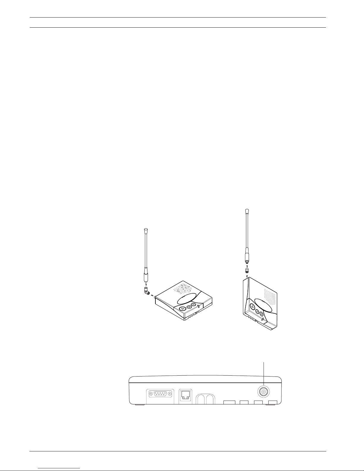
3.2.4 Installing the antenna
1. Use the straight adapter (4) for wall installation or the right angled bended adapter (3)
for installation on a piece of furniture.
2. Fasten the adapter (3) or (4) on the antenna connector (1).
3. Fasten the antenna (2) on the adapter.
2
3
2
4
1
NurseCall Main Unit Installation | en 17
Bosch Security Systems User Manual F.01U.252.699 | V1.1 | 2012.01
3.2.5 Connecting to the mains
The NurseCall Main Unit is powered by an adaptor (230/10 VAC or 115/10 VAC).
1. Plug the power adaptor into a power outlet placed near the unit. It should be easily
accessible at any time.
2. Connect the cable to the socket labeled 10V AC (1), under the unit.
For connector wiring, see Section A.7.2 Power socket (unit bottom), page 59.
3.2.6 Connecting the RS-232
Connect the device to the 9-pole SUB-D connector (1) at the rear part of the housing.
For connector wiring, see Section A.7.3 RS-232 socket (unit rear), page 59.
CAUTION!
In case of a different supply, the equipment must fulfill isolation requirements according to
EN60950 standard (last edition).
1
1
18 en | Installation NurseCall Main Unit
F.01U.252.699 | V1.1 | 2012.01 User Manual Bosch Security Systems
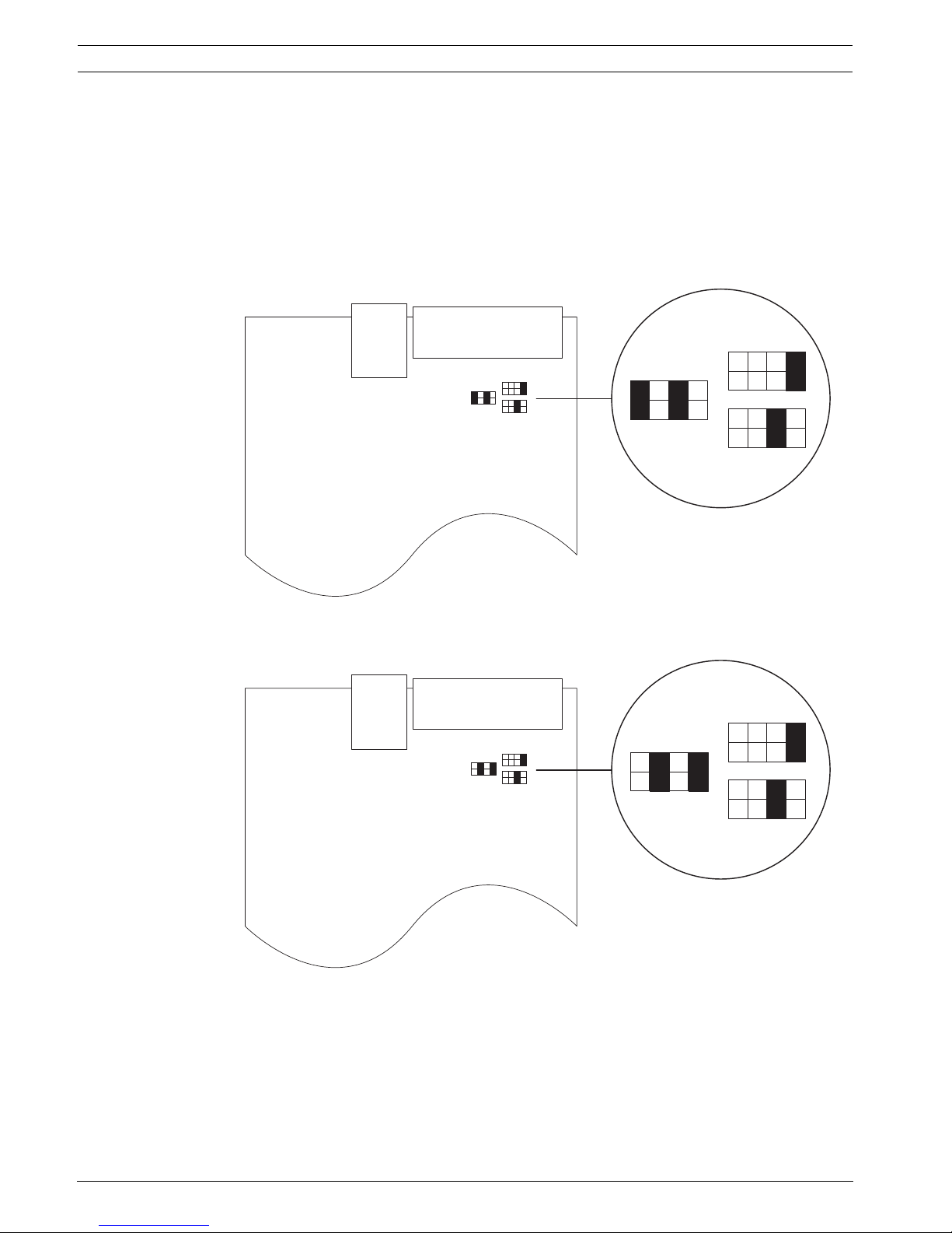
3.2.7 Setting the jumpers on the communication board
1. Disassemble the unit; see Section 7.5.1 Disassembling the unit, page 48.
2. Remove the communication board; see Section Removing the communication board,
page 48.
3. Set the jumpers as required in your configuration. By default the jumpers are set for
connection to a DECT phone system.
Setting the jumpers for a DECT phone system, Alarm Management Software, NPS
programming or Medicall 800:
Setting the jumpers for Paging systems (except Medicall 800) and printers:
4. Assemble the communication board and the unit. This is basically the reverse of the
disassembling procedure, see Section 7.5.1 Disassembling the unit, page 48.
NurseCall Main Unit Installation | en 19
Bosch Security Systems User Manual F.01U.252.699 | V1.1 | 2012.01
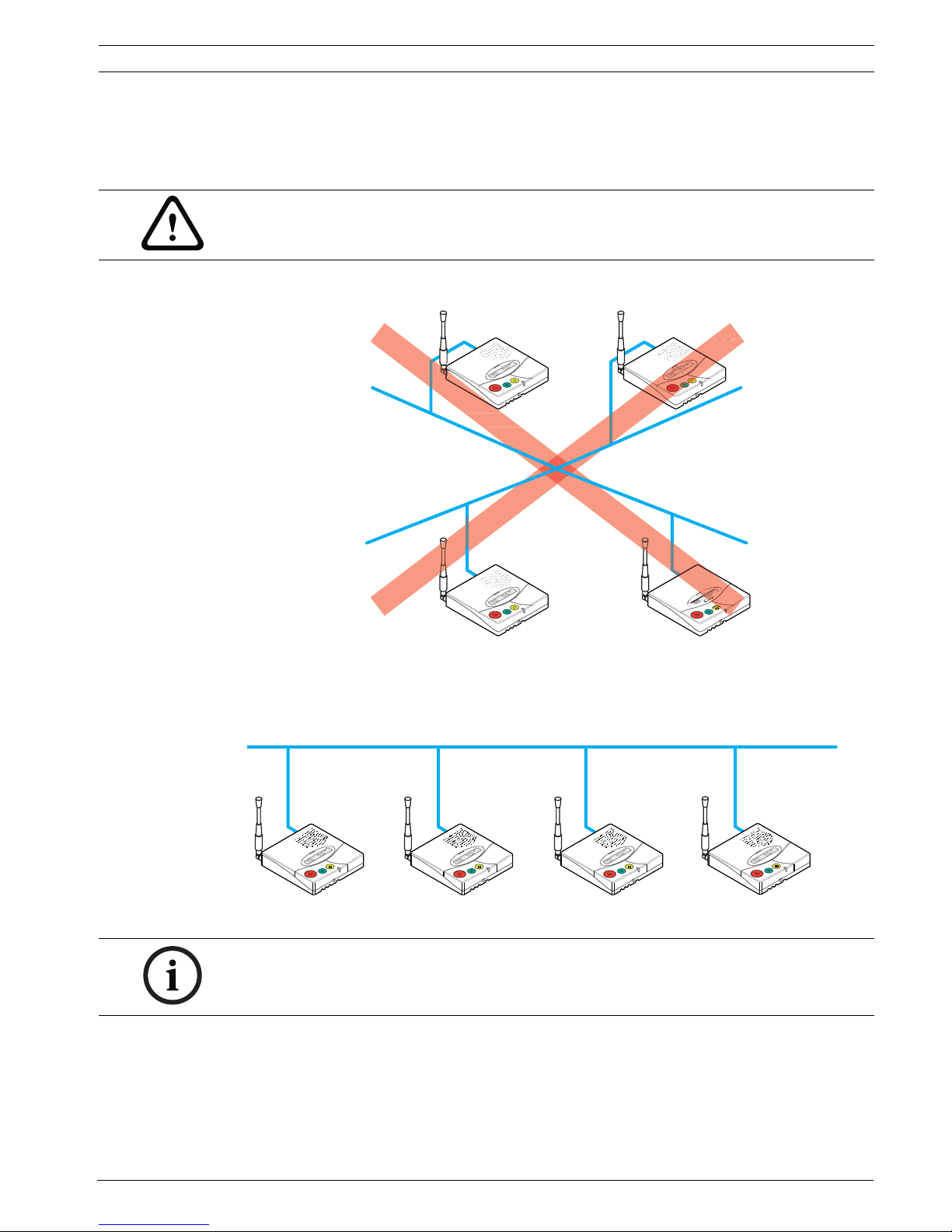
3.2.8 Connecting the RS-485
One NurseCall Main Unit and up to 32 NurseCall Relay Units can be connected to an RS-485
bus. Please contact a specialist for a correct installation.
See Section A.7.4 RS-485 socket (unit rear), page 59 for connector wiring.
Incorrect connection:
Correct connection:
CAUTION!
Do not use a star connection for the RS-485 network!
Relay Unit n
Relay Unit 1
Relay Unit 2
Main Unit
RS-485 bus (1 twisted pair cable)
Relay Unit n
Relay Unit 1
Relay Unit 2
Main Unit
100 Ω
100 Ω
NOTICE!
The NurseCall Main or Relay Units located at the two ends of the bus must be terminated with
a 100 Ohm resistor.
20 en | Installation NurseCall Main Unit
F.01U.252.699 | V1.1 | 2012.01 User Manual Bosch Security Systems
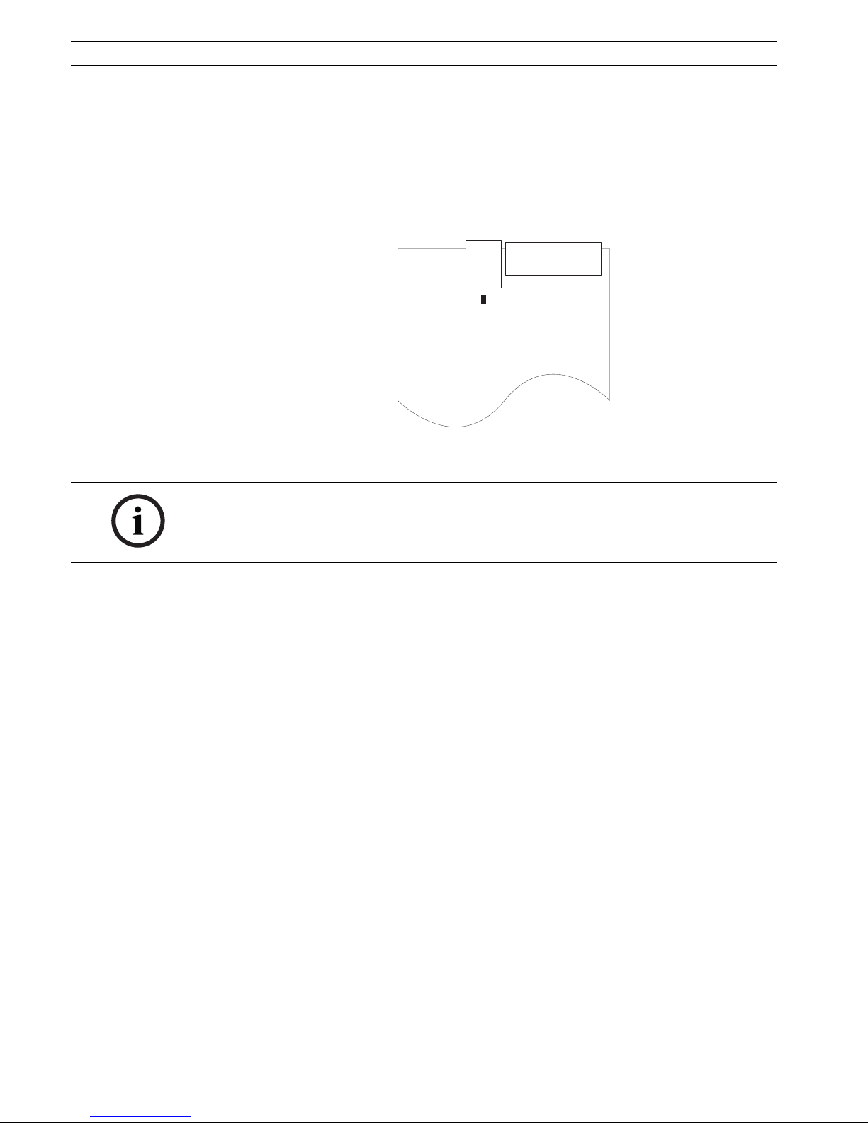
3.2.9 Setting the 100 Ohm termination jumper
Within the NurseCall Main or Relay Units, the RS-485 interface can be configured with a
jumper.
1. Disassemble the unit as described in Section 7.5.1 Disassembling the unit, page 48.
2. Remove the communication board as described in Section Removing the communication
board, page 48.
3. Put the 100 Ohm termination jumper J112 (1).
4. Assemble the communication board and the unit. This is basically the reverse of the
disassembling procedure, see Section 7.5.1 Disassembling the unit, page 48.
1
NOTICE!
If you do not want to disassemble the NurseCall Main Unit, you also can short-out pins 3 and 4
of the connector. This has the same effect as the jumper setting described above.
See Section A.7.4 RS-485 socket (unit rear), page 59 for connector wiring.
 Loading...