

Page 1
Instruction Manual
EN Single Channel,
Color Digital Video
Recorder
Applicable Models:
DVR1EP08, DVR1EP16,
DVR1EP32, and DVR1EP32A
DVR1 Series
Page 2

Important Safeguards
1. Read, Follow, and Retain Instructions - All safety and
operating instructions should be read and followed before
operating the unit. Retain instructions for future reference.
2. Heed Warnings – Adhere to all warnings on the unit and
in the operating instructions.
3. Attachments - Attachments not recommended by the
product manufacturer should not be used, as they may
cause hazards.
4. Installation Cautions - Do not place this unit on an
unstable stand, tripod, bracket, or mount. The unit may
fall, causing serious injury to a person and serious damage
to the unit. Use only manufacturer-recommended
accessories, or those sold with the product. Mount the unit
per the manufacturer's instructions. Appliance and cart
combination should be moved with care. Quick stops,
excessive force, or uneven surfaces may cause the
appliance and cart combination to overturn.
5. Cleaning - Unplug the unit from the outlet before
cleaning. Follow any instructions provided with the unit.
Generally, using a damp cloth for cleaning is sufficient. Do
not use liquid cleaners or aerosol cleaners.
6. Servicing - Do not attempt to service this unit yourself.
Opening or removing covers may expose you to
dangerous voltage or other hazards. Refer all servicing to
qualified service personnel.
7. Damage Requiring Service - Unplug the unit from the
main AC power source and refer servicing to qualified
service personnel under the following conditions:
•When the power supply cord or plug is damaged.
• If liquid has been spilled or an object has fallen into the
unit.
• If the unit has been exposed to water and/or inclement
weather (rain, snow, etc.).
• If the unit does not operate normally, when following
the operating instructions. Adjust only those controls
specified in the operating instructions. Improper
adjustment of other controls may result in damage, and
require extensive work by a qualified technician to
restore the unit to normal operation.
• If the unit has been dropped or the cabinet damaged.
• If the unit exhibits a distinct change in performance, this
indicates that service is needed.
8. Replacement Parts - When replacement parts are
required, the service technician should use replacement
parts specified by the manufacturer, or that have the same
characteristics as the original part. Unauthorized
substitutions may result in fire, electrical shock, or other
hazards.
9. Safety Check - Upon completion of servicing or repairs to
the unit, ask the service technician to perform safety
checks to ensure proper operating condition.
10. Power Sources - Operate the unit only from the type of
power source indicated on the label. If unsure of the type
of power supply to use, contact your dealer or local power
company.
• For units intended to operate from battery power, refer
to the operating instructions.
• For units intended to operate with External Power
Supplies, use only the recommended approved power
supplies.
• For units intended to operate with a limited power
source, this power source must comply with EN60950.
Substitutions may damage the unit or cause fire or
shock.
• For units intended to operate at 24VAC, normal input
voltage is 24VAC. Voltage applied to the unit's power
input should not exceed 30VAC.
User-supplied wiring, from the 24VAC supply to unit,
must be in compliance with electrical codes (Class 2
power levels). Do not ground the 24VAC supply at the
terminals or at the unit's power supply terminals.
11. Coax Grounding - If an outside cable system is connected
to the unit, ensure that the cable system is grounded.
U.S.A. models only--Section 810 of the National Electrical
Code, ANSI/NFPA No.70, provides information regarding
proper grounding of the mount and supporting structure,
grounding of the coax to a discharge unit, size of
grounding conductors, location of discharge unit,
connection to grounding electrodes, and requirements for
the grounding electrode.
12. Grounding or Polarization - This unit may be equipped
with a polarized alternating current line plug (a plug with
one blade wider than the other). This safety feature allows
the plug to fit into the power outlet in only one way. If
unable to insert the plug fully into the outlet, try reversing
the plug. If the plug still fails to fit, contact an electrician to
arrange replacement of the obsolete outlet. Do not defeat
the safety purpose of the polarized plug.
Alternately, this unit may be equipped with a
3-wire grounding plug (a plug with a third pin, for
grounding). This safety feature allows the plug to fit into a
grounding power outlet only. If unable to insert the plug
into the outlet, contact an electrician to arrange
replacement of the obsolete outlet. Do not defeat the safety
purpose of the grounding plug.
13. Lightning - For added protection during a lightning storm,
or when this unit is left unattended and unused for long
periods of time, unplug the unit from the wall outlet and
disconnect the cable system. This will prevent damage to
the unit due to lightning and power line surges.
2
Page 3
3
For Indoor Product
1. Water and Moisture - Do not use this unit near
water - for example, in a wet basement, in an
unprotected outdoor installation, or in any area
classified as a wet location.
2. Object and Liquid Entry - Never push objects of
any kind into this unit through openings, as they
may touch dangerous voltage points or short out
parts that could result in a fire or electrical shock.
Never spill liquid of any kind on the unit.
3. Power Cord and Power Cord Protection - For
units intended to operate with 230VAC, 50Hz,
the input and output power cord must comply
with the latest versions of IEC Publication 227 or
IEC Publication 245.
Power supply cords should be routed so they are
not likely to be walked on or pinched. Pay
particular attention to location of cords and plugs,
convenience receptacles, and the point of exit
from the appliance.
4. Overloading - Do not overload outlets and
extension cords; this can result in a risk of fire or
electrical shock.
For Outdoor Product
Power Lines - An outdoor system should not be
located in the vicinity of overhead power lines,
electric lights, or power circuits, or where it may
contact such power lines or circuits. When
installing an outdoor system, extreme care should
be taken to keep from touching power lines or
circuits, as this contact might be fatal. U.S.A.
models only - refer to the National Electrical
Code Article 820 regarding installation of CATV
systems.
For Rack-mount Product
1. Ventilation - This unit should not be placed in a
built-in installation or rack, unless proper
ventilation is provided, or the manufacturer’s
instructions have been adhered to. The
equipment must not exceed its maximum
operating temperature requirements.
2. Mechanical Loading - Mounting of the
equipment in a rack shall be such that a
hazardous condition is not achieved due to
uneven mechanical loading.
WARNING:
Electrostatic-sensitive device. Use
proper CMOS/MOSFET handling
precautions to avoid electrostatic
discharge.
NOTE: Grounded wrist straps must be worn and proper ESD
safety precautions observed when handling the electrostaticsensitive printed circuit boards.
ATTENTION
OBSERVE PRECAUTIONS
FOR HANDLING
ELECTROSTATIC SENSITIVE
DEVICES
Safety Precautions
Attention: Installation should be performed by
qualified service personnel only in accordance
with the National Electrical Code or applicable
local codes.
Power Disconnect. Units with or without
ON-OFF switches have power supplied to the
unit whenever the power cord is inserted into the
power source; however, the unit is operational
only when the ON-OFF switch is in the ON
position. The power cord is the main power
disconnect for all units.
CAUTION: TO REDUCE THE RISK OF
ELECTRIC SHOCK, DO NOT REMOVE COVER
(OR BACK). NO USER SERVICEABLE PARTS
INSIDE. REFER SERVICING TO QUALIFIED
SERVICE PERSONNEL.
This symbol indicates the presence of
uninsulated “dangerous voltage” within the
product’s enclosure. This may constitute a
risk of electric shock.
The user should consult the operating and
maintenance (servicing) instructions in the
literature accompanying the appliance.
CAUTION: Lithium Battery
Danger of explosion if battery is incorrectly replaced.
Replace only with the same or equivalent type
recommended by the manufacturer. Dispose of used
batteries according to the battery manufacturer’s
instructions.
Page 4
4
Sicherheitshinweise
Achtung! Die Installation sollte nur von qualifiziertem
Kundendienstpersonal gemäß jeweils zutreffender
Elektrovorschriften ausgeführt werden.
Unterbrechung des Netzanschlusses. Geräte mit oder ohne
Netzschalter haben Spannung am Gerät anliegen, sobald der
Netzstecker in die Steckdose gesteckt wird. Das Gerät ist jedoch
nur betriebsbereit, wenn der Netzschalter (EIN/AUS) auf EIN
steht. Wenn das Netzkabel aus der Steckdose gezogen wird, ist
die Spannungszuführung zum Gerät vollkommen unterbrochen.
VORSICHT: UM EINEN ELEKTRISCHEN SCHLAG ZU
VERMEIDEN, IST DIE ABDECKUNG (ODER RÜCKSEITE) NICHT
ZU ENTFERNEN. ES BEFINDEN SICH KEINE TEILE IN DIESEM
BEREICH, DIE VOM BENUTZER GEWARTET WERDEN KÖNNEN.
LASSEN SIE WARTUNGSARBEITEN NUR VON QUALIFIZIERTEM
WARTUNGSPERSONAL AUSFÜHREN.
Das Symbol macht auf nicht isolierte „gefährliche Spannung"
im Gehäuse aufmerksam. Dies kann zu einem elektrischen
Schlag führen.
Der Benutzer sollte sich ausführlich über Anweisungen für
die Bedienung und Instandhaltung (Wartung) in den
begleitenden Unterlagen informieren.
Precauciones de Seguridad
Atención: la instalación la debe realizar únicamente personal
cualificado de conformidad con el National Electric Code o las
normas aplicables en su país.
Desconexión de la alimentación. Las unidades con o sin
interruptores de encendido/apagado reciben alimentación
eléctrica siempre que el cable de alimentación esté conectado a
la fuente de alimentación. Sin embargo, la unidad sólo funciona
cuando el interruptor está en la posición de encendido. El cable
de alimentación es la principal fuente de desconexión de todas
las unidades.
PRECAUCIÓN: PARA DISMINUIR EL RIESGO DE DESCARGA
ELÉCTRICA, NO RETIRE LA CUBIERTA (NI LA PARTE
POSTERIOR). NO EXISTEN PIEZAS DE RECAMBIO EN EL
INTERIOR DEL EQUIPO. EL PERSONAL DE SERVICIO
CUALIFICADO SE ENCARGA DE REALIZAR LAS
REPARACIONES.
Este símbolo indica que existen puntos de tensión peligrosos
sin aislamiento dentro de la cubierta de la unidad. Estos
puntos pueden constituir un riesgo de descarga eléctrica.
El usuario debe consultar las instrucciones de funcionamiento y
mantenimiento (reparación) en la documentación que se
suministra con el aparato.
Sécurité
Attention : l'installation doit exclusivement être réalisée par du
personnel qualifié, conformément au code national d'électricité
américain (NEC) ou au code d'électricité local en vigueur.
Coupure de l'alimentation. Qu'ils soient pourvus ou non d'un
commutateur ON/OFF, tous les appareils reçoivent de l'énergie une
fois le cordon branché sur la source d'alimentation. Toutefois,
l'appareil ne fonctionne réellement que lorsque
le commutateur est réglé sur ON. Le débranchement du cordon
d'alimentation permet de couper l'alimentation des appareils.
ATTENTION : POUR ÉVITER TOUT RISQUE D'ÉLECTROCUTION,
N'ESSAYEZ PAS DE RETIRER LE CAPOT (OU LE PANNEAU
ARRIÈRE). CET APPAREIL NE CONTIENT AUCUN COMPOSANT
SUSCEPTIBLE D'ÊTRE RÉPARÉ PAR L'UTILISATEUR. CONFIEZ
LA RÉPARATION DE L'APPAREIL À DU PERSONNEL QUALIFIÉ.
Ce symbole signale que le produit renferme une « tension
potentiellement dangereuse » non isolée susceptible de
provoquer une électrocution.
Ce symbole invite l'utilisateur à consulter les instructions
d'utilisation et d'entretien (dépannage) reprises dans la
documentation qui accompagne l'appareil.
FCC & ICES INFORMATION
(U.S.A. and Canadian Models Only)
This device complies with part 15 of the FCC Rules. Operation is
subject to the following two conditions:
(1) This device may not cause harmful interference, and
(2) This device must accept any interference received,
including interference that may cause undesired
operation.
NOTE: This equipment has been tested and found to comply
with the limits for a Class A digital device, pursuant to Part 15 of
the FCC Rules and ICES-003 of Industry Canada. These limits
are designed to provide reasonable protection against harmful
interference when the equipment is operated in a commercial
environment. This equipment generates, uses and radiates radio
frequency energy, and if not installed and used in accordance
with the instruction manual, may cause harmful interference to
radio communications. Operation of this equipment in a
residential area is likely to cause harmful interference, in which
case the user will be required to correct the interference at his
expense.
Intentional or unintentional changes or modifications, not
expressly approved by the party responsible for compliance, shall
not be made. Any such changes or modifications could void the
user’s authority to operate the equipment. If necessary, the user
should consult the dealer or an experienced radio/television
technician for corrective action. The user may find the following
booklet, prepared by the Federal Communications Commission,
helpful: How to Identify and Resolve Radio-TV Interference
Problems. This booklet is available from the U.S. Government
Printing Office, Washington, DC 20402, Stock No. 004-00000345-4.
WARNING: This is a Class A product. In a domestic
environment, this product may cause radio interference,
in which case, the user may be required to take adequate
measures.
Page 5
5
Veiligheidsmaatregelen
Attentie: het apparaat mag alleen door gekwalificeerd personeel
worden geïnstalleerd. De installatie dient in overeenstemming
met de nationale elektrische richtlijnen of de van toepassing
zijnde lokale richtlijnen te worden uitgevoerd.
Spanning uitschakelen. Apparatuur met of zonder
aan-uitschakelaar staat onder spanning zolang de stekker is
aangesloten op de wandcontactdoos. De apparatuur is uitsluitend
in werking als de aan-uitschakelaar aan staat. Het netsnoer is de
"hoofdschakelaar" voor alle apparatuur.
VOORZICHTIG: OPEN DE BEHUIZING OF DE ACHTERKANT
VAN HET APPARAAT NIET. ZO VERMINDERT U HET RISICO
OP ELEKTRISCHE SCHOKKEN. IN HET APPARAAT
BEVINDEN ZICH GEEN ONDERDELEN DIE U ZELF KUNT
REPAREREN. LAAT SERVICE EN ONDERHOUD UITVOEREN
DOOR GEKWALIFICEERD PERSONEEL.
Dit symbool geeft aan dat er binnen in het apparaat
ongeïsoleerde, gevaarlijke spanning aanwezig is die mogelijk
elektrische schokken kan veroorzaken.
De gebruiker dient de bedienings- en onderhoudsvoorschriften
te raadplegen in de documentatie die werd meegeleverd met
het apparaat.
Sicurezza
Attenzione: l'installazione deve essere effettuata esclusivamente
da personale tecnico qualificato in conformità con il National
Electrical Code o con le normative locali vigenti.
Scollegamento dell'alimentazione. Le unità dotate o sprovviste di
interruttori ON-OFF vengono alimentate quando si inserisce il
cavo nella presa dell'alimentazione. L'unità è tuttavia in funzione
solo quando l'interruttore ON-OFF si trova nella posizione ON. Il
cavo di alimentazione costituisce il dispositivo di scollegamento
dell'alimentazione principale per tutte le unità.
ATTENZIONE: PER RIDURRE IL RISCHIO DI SCOSSE
ELETTRICHE NON RIMUOVERE LA COPERTURA (O IL
PANNELLO POSTERIORE). L'UNITÀ NON CONTIENE
COMPONENTI INTERNI RIPARABILI DALL'UTENTE. PER
QUALSIASI INTERVENTO, RIVOLGERSI A PERSONALE
TECNICO QUALIFICATO.
Questo simbolo indica la presenza di "tensione pericolosa" non
isolata all'interno del contenitore del prodotto. Ciò comporta
un potenziale rischio di scosse elettriche.
Si consiglia di consultare le istruzioni operative e di
manutenzione (interventi tecnici) contenute nella
documentazione fornita con il dispositivo.
Medidas de Segurança
Atenção: a instalação deve ser executada apenas por técnicos
qualificados da assistência, de acordo com o código eléctrico
nacional ou os códigos locais aplicáveis.
Corte de corrente. As unidades com ou sem interruptores
ON-OFF (ligar/desligar) recebem corrente sempre que o fio de
alimentação está introduzido na fonte de alimentação; contudo, a
unidade apenas está operacional quando o interruptor ON-OFF
está na posição ON. O fio de alimentação destina-se a desligar a
corrente em todas as unidades.
CUIDADO: PARA REDUZIR O RISCO DE CHOQUE
ELÉCTRICO, NÃO RETIRE A TAMPA (OU A PARTE
POSTERIOR). NO INTERIOR, NÃO EXISTEM PEÇAS QUE
POSSAM SER REPARADAS PELO UTILIZADOR. REMETA A
ASSISTÊNCIA PARA OS TÉCNICOS QUALIFICADOS.
Este símbolo indica a presença de "tensão perigosa" não
isolada dentro da estrutura do produto, o que pode constituir
risco de choque eléctrico.
O utilizador deve consultar as instruções de funcionamento
e manutenção (assistência) nos documentos que
acompanham o aparelho.
Zasady Bezpieczeństwa
Uwaga: Instalacja może być wykonywana wyłącznie przez
wykwalifikowanych pracowników obsługi, zgodnie z zasadami
kodeksu National Electrical Code lub innych obowiązujących
norm.
Odłączanie zasilania Niezależnie od wyposażenia w wyłącznik
zasilania, prąd do urządzenia jest doprowadzany zawsze, gdy
przewód zasilania jest podłączony do źródła zasilania; jednak
urządzenie działa tylko wtedy, gdy wyłącznik zasilania jest
włączony. Przewód zasilania jest głównym wyłącznikiem zasilania
we wszystkich urządzeniach.
PRZESTROGA: ABY ZMNIEJSZYĆ RYZYKO PORAŻENIA
ELEKTRYCZNEGO, NIE NALEŻY ZDEJMOWAĆ POKRYWY
GÓRNEJ (ani tylnej). WEWNĄTRZ URZĄDZENIA NIE MA
ŻADNYCH ELEMENTÓW, KTÓRE MOGĄ BYĆ NAPRAWIANE
SAMODZIELNIE PRZEZ UŻYTKOWNIKA. SERWIS NALEŻY
ZLECAĆ WYKWALIFIKOWANYM PRACOWNIKOM OBSŁUGI.
Ten symbol wskazuje na obecność nieizolowanego
„niebezpiecznego napięcia” we wnętrzu urządzenia. Napięcie
to grozi porażeniem elektrycznym.
Użytkownik powinien zapoznać się z instrukcjami obsługi i
konserwacji (serwisu), zamieszczonymi w dokumentacji
towarzyszącej urządzeniu.
Page 6

6
TABLE OF CONTENTS
SECTION 1: INTRODUCTION TO THE DVR1 SERIES DIGITAL VIDEO RECORDERS 9
1.1 Guide to This Manual ..............................................................................................................9
1.2 Unpacking ................................................................................................................................9
1.3 Understanding the DVR1 Series ................................................................................................9
SECTION 2: INSTALLING THE DVR1 ......................................................................................10
2.1 Mounting ................................................................................................................................10
2.2 Connecting the DVR1 ............................................................................................................10
SECTION 3: GUIDE TO THE DVR1 CONTROLS ..................................................................13
3.1 DVR1 Front Panel Controls ....................................................................................................13
3.2 DVR1 Front Panel Display ......................................................................................................13
3.3 Navigating with the DVR1 Controls ......................................................................................14
SECTION 4: DVR1 MAIN MENU PROGRAMMING ..............................................................15
4.1 Overview of the DVR1 Main Menu ........................................................................................15
4.2 Setting the Time/Date ............................................................................................................15
4.3 Configuring Alarms ................................................................................................................15
4.4 Configuring Scheduled Recordings ..........................................................................................16
4.5 Configuring the Recording Parameters ....................................................................................16
4.6 Configuring On-screen Display Options ................................................................................17
4.7 Managing Archive Storage ......................................................................................................17
4.8 Accessing the Advanced Menu ................................................................................................19
4.9 About DSR ............................................................................................................................19
SECTION 5: DVR1 ADVANCED MENU PROGRAMMING ....................................................20
5.1 Overview of the DVR1 Advanced Menu ................................................................................20
5.2 DVR1 Passwords ....................................................................................................................20
5.3 Overwriting the Hard Disk ....................................................................................................21
5.4 Erasing, Deleting, and Recovering Hard Disk Data ................................................................21
5.5 Invoking Audio Recording ......................................................................................................21
5.6 Using the Auto Delete Feature ................................................................................................21
5.7 Configuring Communications ................................................................................................22
5.8 Configuring the Multiplexer Format ......................................................................................22
5.9 Adjusting Picture Qualities ......................................................................................................22
5.10 Locking Out the Front Panel ..................................................................................................22
5.11 Restoring Factory Defaults ......................................................................................................23
5.12 Changing the Password ..........................................................................................................23
SECTION 6: OPERATING THE DVR1 SERIES ........................................................................24
6.1 Initial Startup ..........................................................................................................................24
6.2 Recording ................................................................................................................................24
6.3 Playback ..................................................................................................................................25
6.4 The Search Interface ................................................................................................................26
SECTION 7: ARCHIVING ..........................................................................................................27
7.1 Archiving Applications Explained ..........................................................................................27
Page 7

7
7.1.1 Extended Archiving Applications ..........................................................................................................27
7.1.2 Backup Archiving Applications ............................................................................................................27
7.1.3 Selective/Manual Archiving Applications ..............................................................................................27
7.2 Using CD-Writers ..................................................................................................................27
7.2.1 Minimuum Requirements ....................................................................................................................27
7.2.2 Connecting the CD Recorder ................................................................................................................27
7.3 Creating a CD-ROM with Video Files ....................................................................................28
7.4 Limitations on CD Operations ................................................................................................28
SECTION 8: SERVICE AND RETURNS ....................................................................................29
8.1 Maintenance ............................................................................................................................29
8.2 Factory Service ........................................................................................................................29
APPENDIX A: FACTORY DEFAULT SETTINGS ......................................................................30
APPENDIX B: TECHNICAL SPECIFICATIONS ........................................................................31
APPENDIX C: OBSERVATION SYSTEM QUICK INSTALL GUIDE ........................................33
1.1 Introduction ............................................................................................................................33
1.2 Required Software Version ......................................................................................................33
1.3 Installation ..............................................................................................................................33
1.3.1 Connection of Audio/Video Cable (A/V cable) ......................................................................................33
1.3.2 Connection of Alarm Contact ..............................................................................................................33
1.4 Programming the Observation System Monitor ......................................................................34
1.5 Programming the DVR1 ........................................................................................................34
1.6 Remote Viewing Considerations ..............................................................................................34
APPENDIX D: INSTALLATION GUIDE FOR THE COMBINED BOSCH MULTIPLEXER,
INTUIKEY KEYBOARD & DVR1 SERIES SYSTEM ........................................35
1.1 Overview ................................................................................................................................35
1.2 Required Software Version ......................................................................................................35
1.3 Installation ..............................................................................................................................35
1.4 DVR1 Keyboard Menus ..........................................................................................................36
1.4.1 DVR1 Controls Menu ..........................................................................................................................36
1.4.2 DVR1 Playback Controls Menu ............................................................................................................37
APPENDIX E: RS-232 REMOTE PROTOCOL ..........................................................................38
1.1 Supported Command Sequences ............................................................................................38
1.2 Setting the Clock ....................................................................................................................38
Page 8

8
9
Page 9

SECTION 1: INTRODUCTION TO THE
DVR1 SERIES DIGITAL VIDEO RECORDERS
1.1 Guide to This Manual
This manual contains all of the information necessary to safely install, program, and operate Bosch DVR1 Series
Digital Video Recorders. Step-by-step procedures and sample menus guide you through each phase of the DVR1’s
setup and programming.
The DVR1 package includes the Remote Viewer software, which allows remote access to a DVR1 through a network
interface. Complete installation and operation instructions for the Remote Viewer program are included in this
manual.
1.2 Unpacking
Unpack carefully. This is electronic equipment and should be handled with care to prevent damage to the unit.
Check for the following items:
✔ Digital Video Recorder unit
✔ Installation Instructions (this manual)
✔ Accessories PCB (printed circuit board)
✔ One (1) 12-volt power supply with two (2) power cables
✔ Rack mount kit
✔ Wave Reader software (CD)
✔ Wave Reader Manual
✔ Wave Watch Manual
If any items appear to have been damaged in shipment, replace the item(s) properly in the shipping carton and notify
the shipping company. If any items are missing, notify your nearest Bosch Security Systems, Inc. Sales Representative
or Customer Service Representative:
The Americas: 1 800 326 3270
Europe & Middle East: 31 40 278 1222
Asia Pacific Region: 65 350 1859
NOTE: The shipping carton and all packing materials should be retained, in case transporting the unit is necessary.
This will ensure safe transport of all components.
1.3 Understanding the DVR1 Series
The DVR1 Series of Digital Video Recorders provide a digital alternative to traditional time-lapse VCRs. Digital
video recording allows continuous recording on a hard disk, eliminating the need to replace or rewind videotapes. The
DVR1 Series provide menu-based search capabilities for recorded events, as well as access to live or recorded data via
the Ethernet.
Additionally, the DVR1 Series offer the following operating features:
• Single-channel composite or S-video input/output connections.
• Ample hard disk storage: 80GB for DVR1EP08; 160GB for DVR1EP16; 320GB for DVR1EP32 &
DVR1EP32A.
• Accepts a single camera or multiplexed inputs from most popular multiplexers.
• Multiple recording rates from 0.1 up to 60 pictures per second (pps; also referred to as images per second, or IPS).
• Two hard disk recording modes: continuous recording (overwrite mode) or no overwrite.
• Two recording quality modes: S-video or VHS.
• Compatibility with many archiving devices (see Section 4.7).
• Remote Viewer software allows remote viewing of live or recorded images on a PC, as well as many other features
(see Wave Reader Manual [part # 3935 890 44511] & Wave Watch Manual [part # 3935 890 44711]).
NOTE: Refer to the Bosch Web site, www.boschsecuritysystems.com, for a listing of the latest approved external
archiving devices.
Page 10
10
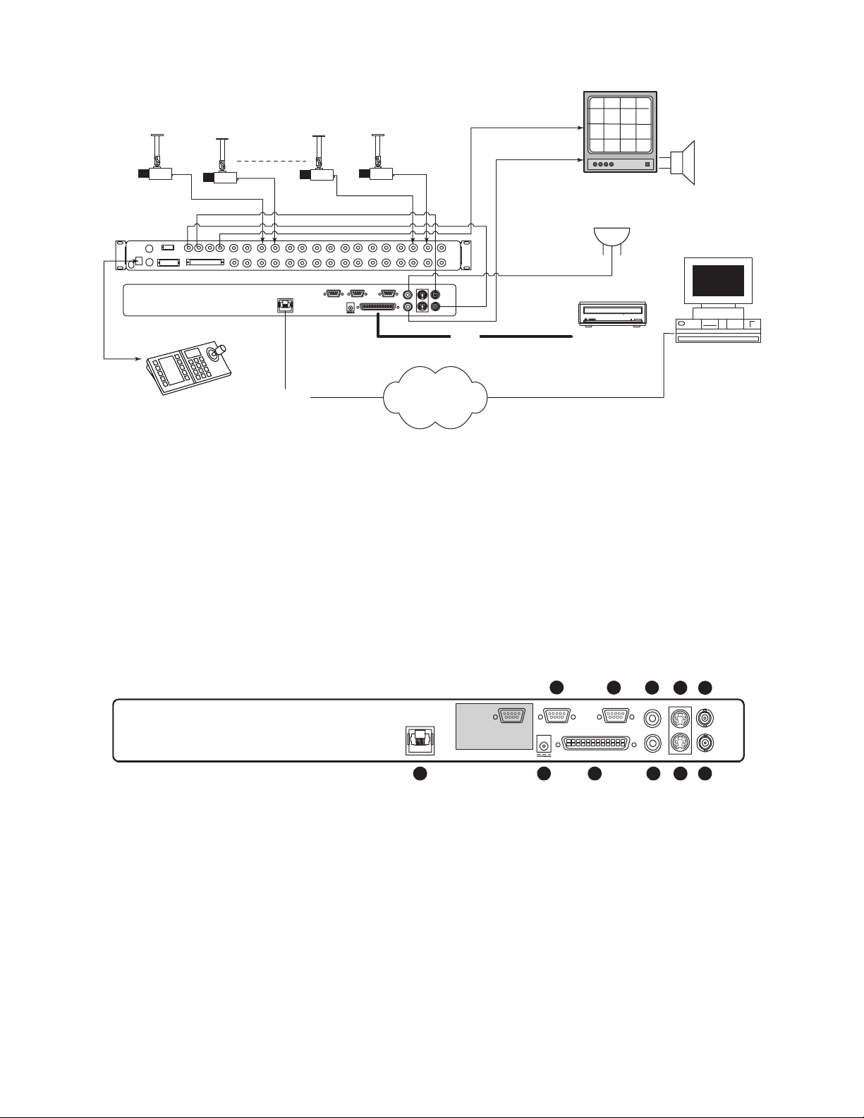
SECTION 2: INSTALLING THE DVR1
Figure 2A – Sample DVR1 System Installation
Figure 2A provides an illustration of a typical DVR1 system installation. Consider the peripheral devices necessary for
your system application, and perform the system connections according to the following installation instructions.
2.1 Mounting
The DVR1 is supplied as a desktop unit. If desired, your unit may be rack mounted using the rack mount kit
(included with the unit). Ensure that the mounting/installation location provides adequate ventilation and protection
from moisture. Do not obstruct the ventilation holes at the sides of the unit.
2.2 Connecting the DVR1
Rear Panel Connections
1. Refer to Figure 2B for details on the input/output connections supplied by the DVR1.
Figure 2B – DVR1 Rear Panel Connections
BOSCH
BOSCH
BOSCHBOSCH
Audio
BOSCH
(Optional)
Microphone
(Optional)
CONSOLE
VCR
SVHS IN
KEYBD
SVHS OUT
Multiplexer
VCR
MON A
MON B
1 2
IN
OUT
ALARM
SDA
3 4 5 6 7 8
ET
ETHERN
100
10/
1 ALARM IN
2 ALARM OUT
3 RECORD START IN
4 ALARM RECORD RESET
5 VEXT PULSE OUT
6 ERROR OUT
7 GROUND
8 VIDEOLOSS OUT
9 DISK END OUT
9 10
ACCESSORI
15
69
12V
13 14
11 12
ES
DC
SC
SI
15 16
232
RS-
S-video
IN
IN
VIDEO
IN
AUDIO
OUT
VIDEO
OUT
AUDIO
S-video
OUT
DVR1
CD-writer
Keyboard
Ethernet
SCSI
Network
15
1 ALARM IN
ETHERNET
10/100
2 ALARM OUT
3 RECORD START IN
4 ALARM RECORD RESET
5 VEXT PULSE OUT
6 ERROR OUT
7 GROUND
8 VIDEOLOSS OUT
9 DISK END OUT
69
1 2
3
ACCESSORIES
12V DC
5 6
RS-232
SCSI
4
1. Ethernet Port: For viewing Live or Recorded Images on a PC via the Ethernet (network).
2. Power Connector: Connect 12 Volt DC external power supply (provided).
NOTE: Ensure that the site's AC Power is stable and within the rated voltage of the external power supply. If the site's
AC power is likely to have spikes or power dips, use power line conditioning or an Uninterruptible Power Supply (UPS).
3. Accessory I/O Port: Used to connect peripheral devices such as alarm devices, alarm relays, or the VEXT (Video External Pulse)
connection (see additional pertinent information, including pinout details, in this section).
4. SCSI Port: For connecting a SCSI compatible archive device.
5. RS-232 Serial Port: Serial port for Flash Upgrading of software. Also used for external control of unit.
NOTE: The RS-232 port does NOT work with a modem. Use a Null Modem type cable (Bosch S1385 cable) to connect to this port.
6. Audio In (specified version only): Unbalanced, RCA style jack.
7. Audio Out (specified version only): Unbalanced, RCA style jack.
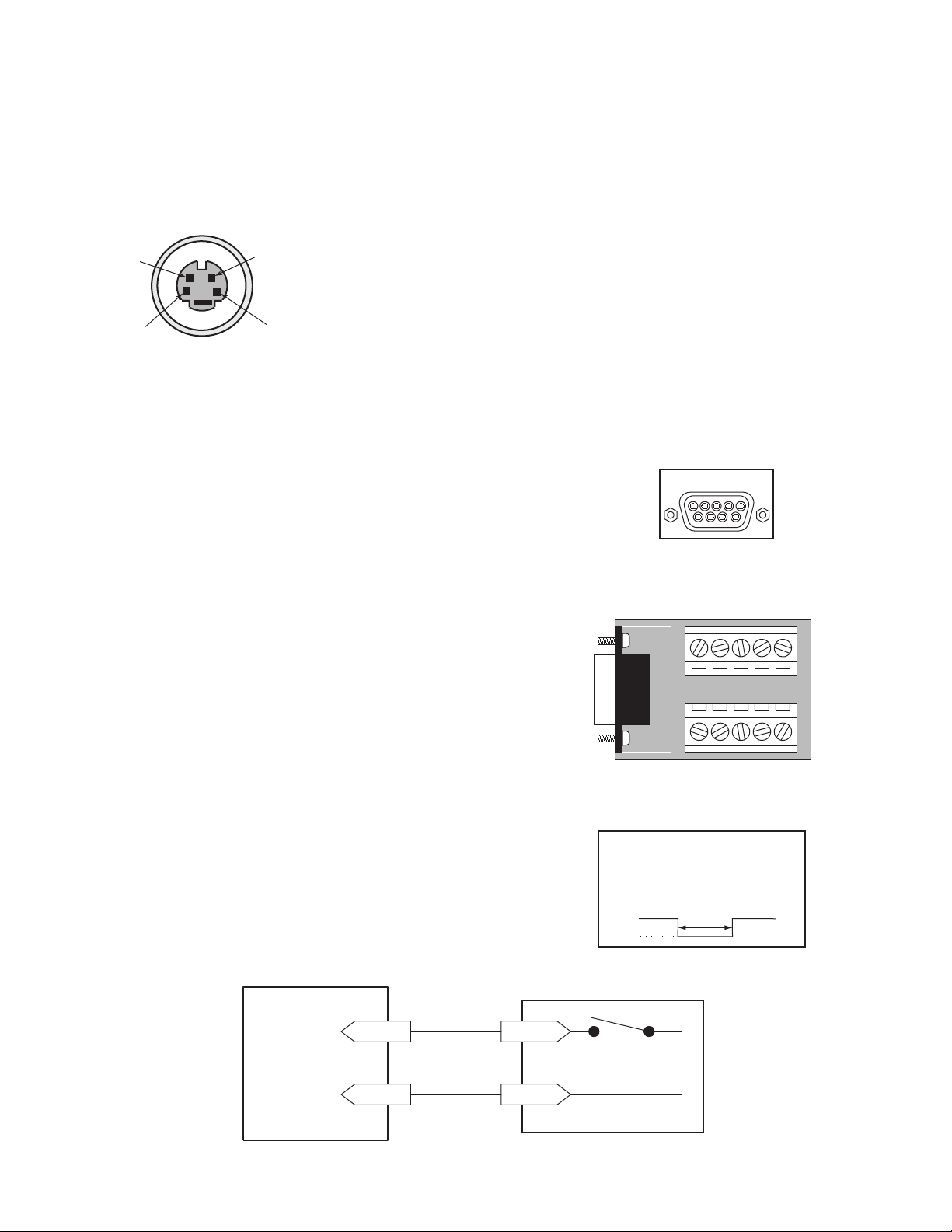
8. S-video In: Y/C video input with 4-pin mini-DIN style connector.
9. S-video Out: Y/C video output with 4-pin mini-DIN style connector.
10. Video In: Composite video input with BNC style connector.
11 . Video Out: Composite video output with BNC style connector.
AUDIO IN
AUDIO OUT
8
S-video IN
VIDEO IN
VIDEO OUT
S-video OUT
91011
7
Page 11
11
2. Connect all peripherals (e.g. cameras, monitors, etc.) to the corresponding inputs/outputs on the DVR1 rear
panel.
CAUTION: DO NOT connect both S-video and Composite inputs at the same time. A hardware conflict will
occur, which could damage the unit.
3. When all connections have been completed, apply power to the system.
S-Video
• Cable must be purchased separately.
Ethernet Port
Ethernet port uses standard pinout configuration.
• For a DVR1 that connects directly to a Hub, use a straight-through connection.
• For a DVR1 that connects directly to a PC, use a crossover connection.
Accessories Port Connections
The rear panel of the DVR1 is equipped with an Accessories Port (DB-9 style
connector). Connect the Accessories PCB (supplied with the unit) to the
Accessories Port, then wire all accessories to the Accessories PCB.
If the Accessories PCB is lost or missing, contact Bosch Customer Service for a
replacement (Part Number 0900-0127a).
As an alternative to using the PCB connector, you may purchase a female
DB-9 connector and perform wiring and connections as detailed in the
following pin-out.
Pin 1: Alarm In Pin 6: Error Out
Pin 2: Alarm Out Pin 7: Ground
Pin 3: Record Start In Pin 8: Videoloss Out
Pin 4: Alarm Record Reset Pin 9: Disk End Out
(future feature)
Pin 5: VEXT Pulse Out Pin 10: Ground
NOTE: Refer to the multiplexer and other peripheral device manuals for
pertinent connection and synchronization information.
Functional descriptions of the connections provided by the DVR1 Accessories Port follow:
Alarm In: An alarm condition can be activated by an Active Low TTL
input, or by relay contact devices such as pressure pads, passive infrareds,
door switches, or similar devices
Normally Open Relay Alarm Connection
DB-9 Connector on
Rear Panel
Accessories PCB
4
2
3
1
Pin Signal
1. GND (Y)
2. GND (C)
3. Y-signal IN or OUT
4. C-signal IN or OUT
Input: Active Low TTL with pull-ups
or Normally Open Relay.
High: 5 V (12 V tolerant)
Low: Ground
ACCESSORIES
15
69
6
7
8
1
9
2
3
4
Minimum Duration: 0.5 Seconds
GND
5
Alarm Input
Ground
Accessories PCB
Pin 1
Normally Open
(Closes During Alarm)
Pin 7 or 10
Typical Alarm Device
Refer to each alarm device's
manual for specific wiring details.
Page 12

12
Alarm Out: The Alarm Output is activated when a teletext alarm is read, or while the
Alarm Input is active. The Alarm output is only active for the duration of the alarm
event.
Record Start In: When activated, this connection places the unit in record mode.
Compatible with the Disk End Out signal from a second unit.
Alarm Record Reset: This feature is for future development and has not yet been
implemented.
VEXT Pulse Out: The Video External Pulse Connection (VEXT) simplifies
multiplexer operation by automatically synchronizing the multiplexer with the DVR1.
The DVR1 sends a VEXT pulse to the multiplexer, indicating that it is ready to
record the next image. The multiplexer responds by sending the next image to the
Video Input on the DVR1.
The VEXT connection is especially beneficial for units configured with dual record
speeds (Normal and Alarm).
NOTE: Use of the VEXT connection is highly recommended when connecting
the unit to a multiplexer.
Error Out: The Error Out signal is activated when the unit experiences any
operational or internal error.
Videoloss Out: The Videoloss Out signal is activated when the unit experiences
loss of video on the selected video input (Composite or S-video).
In the event of loss of video, VIDEOLOSS will be indicated near the upper
left-hand corner of the primary monitor.
Disk End Out: The Disk End Out is activated when there are 5 minutes of
recording space left on the hard disk.
Input: Active Low
High: 12 V
Low: Ground
Current Out: 50 mA Max
Short Circuit Protected.
Low for duration of alarm
Input: Active Low TTL with pull-ups
or Normally Open Relay.
High: 5 V (12 V tolerant)
Low: Ground
Minimum Duration: 0.5 Seconds
Output: Active Low
High: 5 V
Low: Ground (0.8 V Max)
Current Out: 50 mA Max
Short Circuit Protected.
Output: Open Collector
High: Transistor Off
Low: Transistor On
Active When On.
Current Out: 10 mA Max
Minimum Duration: 0.5 Seconds
Page 13

13
SECTION 3: GUIDE TO THE DVR1 CONTROLS
Before attempting DVR1 programming, you should become familiar with the function of the DVR1 controls. This
section provides a summary of the front panel controls and indicators, as well as hints for navigating the DVR1
menus and entering values via the front panel controls.
3.1 DVR1 Front Panel Controls
Figure 3A provides an illustration of the DVR1 front panel controls and their functionality. Figure 3B shows the
components of the Front Panel LCD display.
Figure 3A – DVR1 Front Panel Controls
3.2 DVR1 Front Panel Display
Figure 3B – DVR1 LCD Display
BOSCH
Digital Video Recorder
REC PLAY REV
1 23
STOP PLAY FWD PAUSE
45
8
REC SPD
6
7
9
11
10
PWR LOSS
SEARCH
12
13 15
14 16
17
18
1. Power On Indicator: Indicates power is ON when LED is lit.
2. Record Button: Press RECORD to begin recording.
3. Play Reverse Button: Press PLAY to play back video in reverse at the normal record speed.
4. Stop Button: Press STOP to stop recording or playback.
5. Play Forward Button: Press PLAY FORWARD to play back video at the normal record speed.
6. Pause Button: Press PAUSE to pause playback.
7. LCD: Displays the time, date, mode, and record or playback speed in pictures per second (pps).
(Refer to Figure 3B for details.)
8. Increase Record Speed Button: Press this button to increase the record or playback speed.
9. Decrease Record Speed Button: Press this button to decrease the record or playback speed.
10. Alarm Indicator: Indicates an alarm condition when this LED is lit.
11. Power Loss Indicator: Indicates power loss when this LED is lit.
12. Search Button: Press SEARCH to enter the search filters menu or to activate certain commands.
13. Rewind Button: Press REWIND to perform high-speed reverse playback.
NOTE: Rewind is also used to navigate the menus and may be referred to in this manual as the left arrow button.
14. Single Frame Advance Button: Press this button to perform a single frame advance while in Pause mode.
NOTE: Single Frame Advance is also used to navigate the menus and may be referred to in this manual as
the up arrow button.
15. Single Frame Rewind Button: Press this button to perform a single frame rewind while in Pause mode.
NOTE: Single Frame Rewind is also used to navigate the menus and may be referred to in this manual as
the down arrow button.
16. Fast Forward Button: Press FAST FORWARD to perform high-speed playback.
NOTE: Fast Forward is also used to navigate the menus and may be referred to in this manual as the right arrow button.
17. Menu Button: Press MENU to enter the menu system. Also used to EXIT without saving while in the menu system.
18. Enter Button and LED Indicator : Press ENTER to make or confirm a selection. When lit, this LED indicates
that the menu system is active.
MENU
1
10:55:45A
2
05/19/00
1. Time: Displays the current time in record and stop modes. Displays the time the
event was recorded in play and pause modes.
NOTE: If the letter A follows the time (#1 in the above diagram), the unit is configured
to record or play back audio.
2. Date or Capacity: In record and stop modes, this field displays the current date;
in play and pause modes, it displays the date in which the event was recorded. Or,
depending on the programmed display setting, this field may show the remaining storage
capacity of the hard drive instead (this display is shown in time remaining).
3. Mode: Displays the current mode that the unit is in.
4. Record Speed: Displays the normal record or playback speed in pictures per second (pps).
STOP
60p
3
4
Page 14

14
3.3 Navigating with the DVR1 Controls
Navigating and entering parameter values with the DVR1 controls are designed to be easy and intuitive. Most menus
use the same navigation for programming operations.
Pull-down Menus
Pull-down menus are the top-level menus, and are accessed by pressing MENU. For example, the following DVR1
Main Menu is a pull-down menu.
• Use the Left/Right Arrows to scroll through the items or fields shown in a menu. When the desired item is
highlighted, press ENTER to select that item.
• Choosing an item from a pull-down menu typically leads to a sub-menu (i.e., a pop-up menu). Changes to
operating parameters are usually made in pop-up menus.
• To exit the program menu or menu level (after all parameter changes have been made), press MENU.
Pop-up Menus
Pop-up menus usually have a parameter(s) from which you can select or change the value. A sample pop-up menu is
shown below.
• Use the Left/Right Arrows to move between fields in the menu.
• Press ENTER to select any item.
• Use the Up/Down Arrows to scroll through the values of that particular parameter.
• To save changes and exit the pop-up menu: select [OK] and/or press ENTER.
• To exit the menu without making changes: press MENU or select [CANCEL], and press ENTER.
Programming Notations in this Manual
Throughout the programming sections in this manual, programming instructions appear in special subheadings, as in
the following example:
Main Menu ➝ Record Settings ➝ Normal Record Speed
Meaning: At the Main Menu, select RECORD SETTINGS, then ENTER. This opens another menu. In this
menu, select NORMAL RECORD SPEED, then press ENTER. A pop-up menu will appear.
On-screen Representations
On-screen representations are shown in this manual as follows (note the distinction between items that appear
highlighted on-screen and those that do not):
Not highlighted: Highlighted:
TIME/DATE
ALARMS
TIMER SETTINGS
RECORD SETTINGS
DISPLAY SETTINGS
ARCHIVE SETUP
ADVANCED MENU
ABOUT DSR
TIME/DATE TIME/DATE
TIME/DATE
DATE FORMAT SETUP
SELECT FORMAT
MM/DD/YY
Page 15

15
SECTION 4: DVR1 MAIN MENU PROGRAMMING
4.1 Overview of the DVR1 Main Menu
The DVR1 Series Main Menu allows quick and easy programming of vital system data and operating parameters.
The following table provides a summary of user actions that are accessible via the DVR1 Main Menu.
NOTE: Upon initial power up, the DVR1 will be set to the factory default parameters (see Appendix A for a
complete listing of the Factory Default Settings).
To access the DVR1 Main Menu, press MENU. The menu below will appear on the system’s primary monitor.
4.2 Setting the Time/Date
Main Menu ➝ Time/Date
Use this menu to specify the following:
• The time format: 12 or 24 hours.
• The date format: MM/DD/YY, DD/MM/YY, or YY/MM/DD.
• The time: HH/MM/SS.
• The date: MM/DD/YY/DAY.
4.3 Configuring Alarms
Main Menu ➝ Alarms
Use this menu to specify the following:
• Whether the DVR1 will activate an alarm condition when the unit
detects a signal on the Alarm In connection of the Accessories PCB.
(Parameter: HARDWIRE ALARM – ENABLE/DISABLE.)
• Whether the DVR1 will activate an alarm condition corresponding to the
teletext alarm signal of a multiplexer or other device.
(Parameter: TELETEXT ALARM – ENABLE/DISABLE.)
• Whether the DVR1 will sound its internal buzzer during an alarm condition.
(Parameter: ALARM BUZZER – ENABLE/DISABLE.)
TIME/DATE
ALARMS
TIMER SETTINGS
RECORD SETTINGS
DISPLAY SETTINGS
ARCHIVE SETUP
ADVANCED MENU
ABOUT DSR
SET TIME FORMAT
SET DATE FORMAT
SET TIME
SET DATE
HARDWIRE ALARM ENABLE
TELETEXT ALARM DISABLE
ALARM BUZZER ENABLE
[CANCEL] [OK]
User Action Corresponding Menu Item/Sub-menu
Set Time/Date TIME/DATE
Configure Alarms ALARMS
Configure Scheduled Recordings TIMER SETTINGS
Configure Recording Parameters RECORD SETTINGS
Configure On-screen Display Options DISPLAY SETTINGS
Manage Archive Storage ARCHIVE SETUP
Access the Advanced Menu ADVANCED MENU
View Important Device Information ABOUT DSR
Page 16

16
4.4 Configuring Scheduled Recordings
Main Menu ➝ Timer Settings
This menu allows the scheduling of a timed-recorded event. A sample menu is shown here.
The fields to be programmed in the above menu are as follows:
• Day: The date or day(s) on which the recording will occur. Choose from the following:
1 through 31 (any period of calendar days named)
Monday–Sunday (any individual day)
Monday–Friday (weekdays)
Saturday–Sunday (weekends)
Monday through Sunday (all week long)
• Start: Hours/Minutes of the starting time for the scheduled recording (24-hour clock time). Note that hours and
minutes are edited separately.
• Stop: Hours/Minutes of the ending time for the scheduled recording (24-hour clock time). Note that hours and
minutes are edited separately.
• Spd (pps): Capture rate for the scheduled, normal recording in pictures per second. Choose from the following:
60, 30, 20, 10, 5, 3, 2, 1, 0.5, 0.2, 0.1, 0.0*
*NOTE: 0.0 corresponds to Alarm Only recording.
• Quality: Choose from either SVHS (highest picture quality) or VHS (standard picture quality, with a longer
recording time).
• On/Off: Choose from one of three parameters:
On (recording starts as scheduled)
Off (recording does not start)
Delete (all recording schedule parameters are deleted)
NOTE: The fields in the Timer Settings menu can be edited easily using the Left/Right Arrows to move between
fields and Up/Down Arrows to scroll through the various options at each parameter. When you finish setting the
parameters, press ENTER. Use the Left/Right Arrows to navigate, then highlight [OK], and press ENTER.
4.5 Configuring the Recording Parameters
Main Menu ➝ Record Settings
This menu allows you to set the recording speed and quality for both normal and
alarm conditions. Use this menu to specify the following:
• Record input (composite video or S-video) on the DVR1 rear panel.
• Record speed (in pictures per second) for normal recording.
• Record speed (in pictures per second) for an alarm condition.
• Video quality (i.e. compression ratio/image quality) for recorded images (SVHS or
VHS). Note that higher compression (VHS) corresponds to standard quality images,
with a longer recording time.
NOTE: If a single camera input is connected to the unit, select NONE. See Section 5.8 for details on Multiplexer
applications.
DAY START STOP SPD (pps) QUALITY ON/OFF
31 16:45 17:05 20 VHS ON
SAT 7:55 8:10 10 SVHS OFF
MON-FRI 9:56 11:05 60 VHS ON
SAT-SUN 14:23 14:50 60 SVHS ON
MON-SUN 2:23 3:34 20 VHS OFF
-- --:-- --:-- -- -- --
[OK]
EDIT MODE HIT "ENTER" TO TOGGLE EDIT MODE
RECORD INPUT
NORMAL RECORD SPEED
ALARM RECORD SPEED
VIDEO QUALITY
Page 17

17
4.6 Configuring On-screen Display Options
Main Menu ➝ Display Settings
Use this menu to specify the status information to be displayed on the primary
monitor (usually shown in the upper right or upper left corner of the screen).
Each of the following parameters may be set ON or OFF for the on-screen
display:
• Current time and date.
• Remaining amount of time before the hard disk runs out of record capacity
(automatically counts down from days/hours to hours/minutes to
minutes/seconds).
NOTE: Record capacity will only display if:
The unit is recording and
The hard disk overwrite mode is set to no overwrite or overwrite once mode (see Section 5.3).
NOTE: Turning this parameter ON will also show the record capacity on the front panel LCD display,
replacing the date field.
• Status of a system archive device connected (i.e. ready/not ready for recording).
• Time and date of the last alarm. Note that the system displays NONE if no previous record(s) of alarm(s) exist.
• Record and Playback Speed are displayed
• During Playback, the time/date in which the recording was made.
4.7 Managing Archive Storage
NOTE: For more information regarding archiving, refer to the Archiving.
Due to the complexity of the Archive Setup process, detailed instructions follow.
Main Menu ➝ Archive Setup
Use this menu to accomplish the following:
• Select data to be archived and begin the archiving process.
• Restore data from the archive device.
• Turn Background Archiving On or Off.
• Set Archive Overwrite mode.
• Erase Disk Array.
Main Menu ➝ Archive Setup ➝ Selective Archive
The Selective Archive feature allows archiving of recorded data from the hard disk of the DVR1 to an archive device.
If the archive device is a CD-writer, you must play back the archived video from a PC’s CD-ROM drive using the
Remote Viewer software (included with the DVR1 package).
The Archive Search Filters Menu allows you to search the hard disk for recorded events (e.g., an alarm condition or a
previous recording session), then select those events to be archived for later viewing (note that each activation of
Record mode is considered to be a separate recording session).
Use this sub-menu to specify:
• Start and stop date of the search.
• Start and stop time of the search.
• Which camera(s) to search.
• A search for recorded alarms.
NOTE: The default settings for Selective
Archive are set to show a list of all of the
files that are on the hard drive. It may be
necessary to limit the size of an archive file
so that it will fit on the archive medium.
The file size for archiving (time span) can be
customized by designating start/stop time
and date within the archive search filters
window. File size can be further reduced by
specifying only the cameras of interest.
CURRENT TIME / DATE
RECORD CAPACITY
ARCHIVE STATUS
LAST ALARM
RECORD/PLAYBACK SPEED
PLAYBACK TIME / DATE
SELECTIVE ARCHIVE
RESTORE FROM ARCHIVE
BACKGROUND ARCHIVE
ARCHIVE OVERWRITE MODE
ERASE ARCHIVE MEDIUM
ARCHIVE SEARCH FILTERS
START STOP
DATE: 12/25/00 [ ] 01/01/01 [ ]
(MM/DD/YY) (MM/DD/YY)
START STOP
TIME: 11:11:21 [ ] 12:34:34 [ ]
1 2 3 4 5 6 7 8
CAMERA: [ ][ ][ ][ ][ ][ ][ ][ ]
ALARM: [ ]
[CANCEL] [START SEARCH]
Page 18

18
When all required search criteria has been entered, highlight [START SEARCH], then press ENTER. The Archive
Search Results window will appear.
Use the Left/Right Arrows to navigate the Search Results menu, highlighting the recorded event you wish to select.
Use the Up/Down Arrows to select a recorded event by placing [X] in the check box.
To begin archiving the selected event(s), press SEARCH. The Archiving progress
bar will appear. Press ENTER to cancel archiving at any time.
When the unit has finished archiving, the Archiving Completed message will appear.
Press ENTER to acknowledge the message and complete the archiving process.
Main Menu ➝ Archive Setup ➝ Restore From Archive
This menu is used to either play back
archived video from a disk array archive, or
restore the video to the DVR1’s hard drive.
NOTE: If video was archived on a
CD-ROM, you must play back video from a
PC using the Remote Viewer software (no
audio capabilities are present in this archive
format).
The Restore Search Filters menu functions
similar to the Archive Search Filters menu
(as described previously). When the search
completes, a Restore Search Results menu
appears.
Main Menu ➝ Archive Setup ➝ Background Archive
This archive feature enables automatic and continuous archiving in the background while other system operations
continue (i.e., all information going to the DVR1 hard drive is continuously sent to the DVAA Series Disk Array). If
this mode is enabled, the archive device must provide the required data transfer and storage capacity.
NOTE: Background Archiving should never be used with CD-writer archive devices or with the unit recording at
the 60 ips recording rate.
Main Menu ➝ Archive Setup ➝ Archive Overwrite Mode
This setting determines what happens when the archive device is full. The three options are: Write once, No
overwrite, and Continuous.
ARCHIVE SEARCH RESULTS
START DATE START TIME SIZE (MB)
000 11/28/00 17:52:14 26842 [ ]
001 11/29/00 9:35:20 2062 [ ]
002 11/29/00 10:00:04 278 [X]
003 11/29/00 10:03:25 66 [X]
SELECTED [ 383 ](MB)
AVAILABLE ON TARGET MEDIUM [ 652 ](MB)
"ENTER" TO PLAY "SEARCH" TO ARCHIVE
ARCHIVING...
[CANCEL]
MESSAGE
ARCHIVING COMPLETED
[OK]
RESTORE SEARCH FILTERS
START STOP
DATE: 12/25/00 [ ] 01/01/01 [ ]
(MM/DD/YY) (MM/DD/YY)
START STOP
TIME: 11:11:21 [ ] 12:34:34 [ ]
1 2 3 4 5 6 7 8
CAMERA: [ ][ ][ ][ ][ ][ ][ ][ ]
ALARM: [ ]
[CANCEL] [START SEARCH]
Page 19

19
• Write Once: When the archive device is full, archiving stops. Archiving will resume after the user acknowledges
that the archive device is full and that archiving should resume.
• No Overwrite: When the archive device is full, archiving stops. Archiving will resume only after a user enters the
advanced menu, manually erases the media, and resumes archiving.
• Continuous: When the archive device is full, archiving will continue, writing over the oldest video first.
Main Menu ➝ Archive Setup ➝ Erase Archive Medium
The Erase Archive Medium feature is used to erase the archive media.
NOTE: Before starting the erasing process, the DVR1 must be set to Selective
Archive, and Background Archive must be set to OFF.
To erase the archived data, press ENTER. The Erasing Media progress bar appears. Press ENTER to cancel.
When the unit is finished erasing the pointers to the data, the message box at right appears. Press ENTER to
acknowledge the message.
4.8 Accessing the Advanced Menu
For information on accessing the Advanced Programming menu, please refer to
Section 5 in this manual. Note that the Advanced Menu is password protected.
4.9 About DSR
Main Menu ➝ About DSR
This screen allows the user to view important device information at a single glance.
ERASING MEDIA . . .
[CANCEL]
MESSAGE
ARCHIVE MEDIUM ERASED
[OK]
SERIAL NUMBER:
SOFTWARE VERSION:
SOFTWARE DATE:
SOFTWARE CHECKSUM:
BOOT CODE VER. :
DISK SIZE:
V2E1-F92-290001
2.00
SEP 17 2002 15:20:06
1BB200CE
1.01
327.86 GB
ETHERNET ENABLE:
ETHERNET ADDRESS:
HARDWARE ADDRESS:
DISABLED
3.18.173.10
00-B0-19-FF-03-AE
[OK]
Page 20

20
SECTION 5: DVR1 ADVANCED MENU PROGRAMMING
5.1 Overview of the DVR1 Advanced Menu
Enhanced DVR1 operating features are programmed via the Advanced Menu. The following table provides a
summary of these actions that are accessed via the DVR1 Advanced Menu.
Press MENU to enter the DVR1 Main Menu. Use the Left/Right Arrows to highlight the ADVANCED MENU
title and press ENTER. The Advanced Menu (shown below) appears.
IMPORTANT NOTE: Please review the information in Section 3 regarding navigation through the DVR1
menus. Advanced Menu programming should be designated to qualified systems personnel only.
5.2 DVR1 Passwords
The DVR1 Series is equipped with two (2) passwords.
The first password provides access to the DVR1’s Advanced Menu. This password can be changed by the System
Administrator to prevent unauthorized access to the Advanced Menu functions. Store the password in a secure location.
The default password for the Advanced Menu is 0000, as stated in Section 5.11. The second password is used to set
the DVR1 to its original factory default settings. This password cannot be altered and is set (permanently) at 0000.
Accessing the Advanced Menu Using the Password
1. Select ADVANCED MENU from the Main Menu, then press
ENTER. The Password Box appears.
2. Enter the Advanced Menu password. Use the Up/Down
Arrows to select a character, then press ENTER to move to the
next character.
3. Pressing ENTER on the last character completes password entry. If the password was correctly entered, the
Advanced Menu is displayed.
DISK OVERWRITE MODE
DISK MAINTENANCE
AUDIO RECORD SETTING
AUTO DELETE MODE
COMMUNICATIONS
MULTIPLEXER FORMAT
ADJUST PICTURE
FRONT PANEL LOCK
FACTORY SETTINGS
CHANGE PASSWORD
User Action Corresponding Menu Item/Sub-menu
Overwrite the Hard Disk DISK OVERWRITE MODE
Erase, Delete, and Recover Hard Disk Data DISK MAINTENANCE
Invoke Audio Recording AUDIO RECORD SETTING
Use the Auto Delete Feature AUTO DELETE MODE
Configure Communications COMMUNICATIONS
Configure Multiplexer Format MULTIPLEXER FORMAT
Adjust Picture Qualities ADJUST PICTURE
Lock Out the Front Panel FRONT PANEL LOCK
Restore Factory Defaults FACTORY SETTINGS
Change the Password CHANGE PASSWORD
PASSWORD BOX
PLEASE ENTER THE PASSWORD!
– – – –
Page 21

21
5.3 Overwriting the Hard Disk
Advanced Menu ➝ Disk Overwrite Mode
Use this menu to specify how disk overwrite issues are handled
once the hard disk becomes full. Select one of three options:
• No Overwrite (i.e., recording stops when the disk is full). An
on-screen message indicates when the disk is full and the unit
has stopped recording. You must acknowledge the message by
pressing ENTER. Note that recording will not continue until
the data is either erased or deleted.
• Overwrite Once. Recording always starts at the end of the last recording. The unit overwrites all previously
recorded data, then stops before it overwrites any newly recorded data (from the current record session). When the
end of the disk is reached, the unit displays an on-screen message stating that the disk is full. You must
acknowledge the message by pressing ENTER. Note that recording will not continue until RECORD is pressed.
• Continuous Overwrite. Recording always starts at the end of the last recording. When the disk is full, recording
continues by overwriting the oldest video first. In this mode, the unit never stops recording (note that the LCD
display does not count down the remaining time till the hard disk is full).
5.4 Erasing, Deleting, and Recovering Hard Disk Data
Advanced Menu ➝ Disk Maintenance
Three options are provided for disk maintenance:
• Delete Video: Once video has been deleted, it may be restored with the
Undelete option if the video has not been overwritten.
• Undelete Video: Restores video if it has not yet been overwritten.
• Erase Video: Video is removed with no possibility of restoration.
5.5 Invoking Audio Recording
Advanced Menu ➝ Audio Record Setting
Use this menu to accomplish the following:
• Select OFF to disable the audio recording capability.
• Select G.711 to enable the audio recording capability.
5.6 Using the Auto Delete Feature
Advanced Menu ➝ Auto Delete Mode
Configuring the unit with the Auto Delete mode ON prevents the unit from displaying or archiving any
data that is more than 30 days old. This feature may be required by law in some jurisdictions; please
consult your local authority. Choose from 7 to 99 days, or OFF (30 Days is the default setting).
DISK OVERWRITE MODE
SELECT MODE
CONTINUOUS OVERWRITE
OFF
G.711 (64kb/s)
OFF
ON
DELETE
UNDELETE
ERASE DISK
ADM SETTING
MESSAGE
[99] DAYS
ADM WILL CHANGE. ARE YOU SURE?
[YES]
Page 22

22
5.7 Configuring Communications
Advanced Menu ➝ Communications
Use this menu to specify the following (select one only):
• Data transfer rate for the RS-232 serial port (select 1200 to 57,600 baud).
• Enable or disable Ethernet connection (network address) settings for the unit.
IP address, Subnet Mask, and Gateway. Contact your IT
department for details regarding basic network configuration.
• POTS Setup (Plain old telephone system): The default modem
string (shown below) is for use with Hayes Accura 56k, Diamond
Supra Express 56k, and 5686 US Robotics modems in their default
conditions. Consult the modem manual before making any
changes. It is strongly recommended that the modem initialization
string only be modified by a qualified technician.
5.8 Configuring the Multiplexer Format
Advanced Menu ➝ Multiplexer Format
The DVR1 Series recorders are compatible with several brands of multiplexers. Use this menu
to specify the type of multiplexer connected to the DVR1. Making the correct selection for
your system configuration ensures proper playback.
NOTE: If a single camera input is connected to the unit, select NONE.
NOTE: The list of compatible multiplexers continues to expand. Please see the Bosch Web
site at www.boschsecuritysystems.com for the most current listing.
5.9 Adjusting Picture Qualities
Advanced Menu ➝ Adjust Picture
Use this menu to specify the Brightness, Contrast, and Saturation of the video input.
Adjustments made to the video input affect images being recorded, as well as the current display.
For each of these parameters, use the Left/Right Arrows to navigate the fields in the
sub-menu. Use the Up/Down Arrows to increase/decrease the setting.
5.10 Locking Out the Front Panel
Advanced Menu ➝ Front Panel Lock
This menu option locks or unlocks the front panel. Exception: the Main Menu will still
display when MENU is pressed.
ETHERNET SETTINGS
ETHERNET : DISABLE
IP ADDRESS : 10. 90.253.000
SUBNET MASK : 255.255. 0. 0
GATEWAY : 10. 90. 0. 1
[CANCEL} [OK]
BAUD RATE
ETHERNET SETTINGS
MODEM SETTINGS
NONE
KALATEL
ROBOT
DM
BOSCH
PELCO
SANYO
PHILIP’S
OBSERVATION
SYSTEM
NAVCO
ATV
ATV QSP
VISTA VLM
QSI
BRIGHTNESS
CONTRAST
SATURATION
UNLOCK KEYBOARD
LOCK KEYBOARD
POTS SETUP
MODEM INIT STRING : AT&F1&K3M0E1Q0V1S0=0&R2&C1&D0&H1
[DEFAULT MODEM STRING] [CANCEL] [OK]
@ABCDEFGHIJKLMNOPQRSTUVWXYZ [ \ ] ^
Page 23

23
5.11 Restoring Factory Defaults
Advanced Menu ➝ Factory Settings
Use this menu to restore the DVR1 to the factory defaults.
NOTE: When the factory settings are restored, all programmed
settings and volume partitions for archive retrieval are erased.
The factory password is fixed at 0000. Therefore, you can
repeatedly press ENTER, and press ENTER to complete entry
and restore the unit to its factory default settings.
5.12 Changing the Password
Advanced Menu ➝ Change Password
Use this menu to change the Advanced Menu Password. It is
recommended that the System Administrator change this
password to prevent unauthorized access to the menu.
Use the Up/Down Arrows to select a character, then press ENTER
and move to the next character.
Pressing ENTER on the last character opens the Confirmation Box.
Reenter the New password.
Pressing ENTER on the last character completes the password
selection.
If the password in the Confirmation Box matches the
password from the Password Box, the message at right will
appear.
Press ENTER to select [OK] and exit the menu.
If the password in the Confirmation Box does not match the
password from the Password Box, the message at right will
appear.
Press ENTER to select [OK] and exit the menu.
PASSWORD BOX
ENTER A NEW PASSWORD
O – – –
CONFIRMATION BOX
PLEASE RE-ENTER THE PASSWORD
O – – –
MESSAGE
THE NEW PASSWORD HAS BEEN ACCEPTED
[OK]
MESSAGE
THE PASSWORD WAS NOT CHANGED!
[OK]
PASSWORD BOX
PLEASE ENTER THE FACTORY PASSWORD
O – – –
Page 24

24
SECTION 6: OPERATING THE DVR1 SERIES
Operating the DVR1 requires general knowledge in three areas:
• Recording
• Playback
• Searching
Certain operating parameters must be set/programmed as part of initial startup of the DVR1. These activities are
outlined in the following section.
6.1 Initial Startup
On initial power-up of the DVR1, the following settings must be programmed:
• Time/Date
• Alarms
• Password
Please refer to Main Menu Programming, Section 4 for detailed information regarding these functions.
6.2 Recording
To begin recording, press REC. The message, RECORD appears briefly in the upper lefthand corner of the primary monitor. The unit always starts recording at the end of the
previously recorded data.
Recording continues until one or more of the following occurs:
• Another mode is selected.
• The disk is full (No Overwrite and Overwrite Once modes). See Section 5.3 for details regarding Disk
Overwrite modes.
• Video loss is detected. In the event of video loss, VIDEOLOSS will be indicated in the upper left-hand corner of
the primary monitor.
Figure 6A - LCD in Record Mode
Normal Recording
The unit records at the normal record speed until an alarm condition is detected. The normal record
speed is indicated on the LCD and can be altered using Up/Down Record Speed, or in the menu
system.
For information about altering the normal record speed from the menu system, see Section 4.5.
The normal record speed can be altered while the unit is recording. The unit continues recording
while the menu system is active.
Alarm Recording
When an alarm condition is detected, the unit automatically switches to the alarm record speed.
The alarm condition is indicated in several ways:
• The word ALARM is displayed on the primary monitor, in the upper left-hand corner of the screen.
• The red LED Alarm Indicator on the front panel of the unit is lit.
• The internal buzzer sounds, if activated via the menu. For information about activating the internal
buzzer during alarms, see Section 4.3.
• By an external device connected to the alarm output of the unit (if the unit is configured with an
alarm output).
• The alarm record speed cannot be changed using Up/Down Record Speed on the front panel; it must be changed
via the menu system. See Section 4.5 for details.
• The front panel LCD displays the record speed during an alarm condition. The unit returns to the normal record
speed once the alarm condition ends.
Record Button
Record Speed
Buttons
Alarm
Indicator
REC
1
10:55:45A
2
11/17/00
1. Current Time
2. Current Date
REC
0.2p
3. Record Mode Indicated
4. Normal Record Speed in
Pictures per Second
3
4
REC SPD
Page 25

25
Disk Full Notification
This message will appear on the primary monitor to indicate
that the unit has stopped recording because the disk is full.
In No Overwrite mode, the unit will not record over
previously recorded data. To continue recording, the user
must acknowledge the disk full message by pressing
ENTER, then ERASE (or DELETE).
In Overwrite Once mode: The user must acknowledge the on-screen message by pressing ENTER.
The unit will resume recording when the user presses RECORD.
6.3 Playback
Figure 6B - LCD during Playback
Play Forward
To begin normal playback in the forward direction, press Play Forward.
Playback is indicated via the following:
• PLAY appears briefly in the upper left-hand corner of the primary monitor.
• PLAY> appears on the LCD.
Reverse Play
To begin reverse playback, press Play Reverse. Reverse playback is indicated via the following:
• REVERSE PLAY appears briefly in the upper left-hand corner of the primary monitor.
• PLAY< appears on the LCD.
If there is only one recording session on the hard disk, the unit will indicate START OF DATA on
the primary monitor.
Playback Speed
The unit plays back the data at the rate at which it was recorded. The user can alter the playback
speed using Up/Down Record Speed.
Altering the playback speed overrides the speed of any incoming alarms. To clear the override, press
STOP, then PLAY to resume playback at the speed that the data was recorded.
NOTE: For clear audio, playback should be at the same speed at which it was recorded.
Fast Forward
During playback, pressing Fast Forward allows viewing of data at a faster than normal rate.
Fast Forward is indicated via the following:
• FAST FORWARD appears briefly in the upper left-hand corner of the primary monitor.
• FFWD appears on the LCD.
MESSAGE
DISK FULL. RECORDING HAS STOPPED.
[OK]
Play Forward
Button
Play Reverse
Button
Record Speed
Buttons
Fast Forward
Button
1
12:34:45A
2
12/17/00
1. Time the Data was Recorded
2. Date the Data was Recorded
(If the letter A precedes the
record rate, the unit is configured to
record or play back audio).
PLAY
0.2p
3. Play Forward Mode Indicated
4. Normal Record Speed in
Pictures per Second
3
4
PLAY FWD
PLAY REV
REC SPD
Page 26

26
Rewind
During playback, press REWIND to view the data (in reverse) at a faster than normal rate.
Rewind is indicated via the following:
• REWIND appears briefly in the upper left-hand corner of the primary monitor
• REW appears on the LCD.
Pause
During playback, press PAUSE to pause playback and display a single frame on-screen.
Pause is indicated via the following:
• PAUSE appears briefly in the upper left-hand corner of the primary monitor.
• PAUSE appears on the LCD.
Single Frame Advance & Single Frame Rewind
During Pause mode, press Single Frame Advance or Single Frame Rewind
to view the frame directly before or after the frame displayed on-screen.
Start of Data & End of Data
If the start or end of data is encountered during playback, START OF DATA or END OF DATA is indicated in the
upper left-hand corner of the primary monitor.
6.4 The Search Interface
The Search Interface feature allows the user to search the hard disk for recorded events, such as an
alarm condition or a previous recording session.
NOTE: Each time the Record mode is activated, it is considered to be a separate recording session.
To enter the Search Filters menu, press SEARCH. The Search Filters menu is displayed on the
primary monitor.
Use this screen to specify the following:
• Start and stop date of the search.
• Start and stop time of the search.
• Which cameras to search exclusively.
• Which recorded alarms are to be searched.
Use the Left/Right Arrows to navigate between the
various fields in the menu. Use the Up/Down
Arrows to scroll through and change the available
parameters for each field. When all search criteria has
been specified, press ENTER to exit the Edit mode,
then highlight [START SEARCH] and press
ENTER.
The Search Results menu will
appear.
Use the Up/Down Arrows to select a
recorded event. Press ENTER to
select the event, or press MENU to
exit the Search Results menu.
Rewind Button
Pause Button
Single Frame
Rewind Button
Single Frame
Advance Button
Search Button
PAUSE
SEARCH
START STOP
DATE: 12/25/00 [ ] 01/01/01 [ ]
(MM/DD/YY) (MM/DD/YY)
SEARCH FILTERS
START STOP
TIME: 11:11:21 [ ] 12:34:34 [ ]
CAMERA: [ ] [ ] [ ] [ ] [ ] [ ] [ ] [ ]
ALARM: [ ]
1 2
[CANCEL]
3 4 5 6 7 8
[START SEARCH]
SEARCH RESULTS
START DATE START TIME DAYS HH MM SS
000 01/01/20 00:07:14 0 00:00:36
001 01/01/20 23:35:20 0 00:08:11
002 02/12/20 23:43:30 0 00:33:49
003 02/12/20 00:17:23 0 01:38:18
"ENTER" TO PLAY EVENT
Page 27

27
SECTION 7: ARCHIVING
7.1 Archiving Applications Explained
The following sections explain the usage of the Extended Archiving, Backup Archiving, and Selective/Manual
Archiving applications for the DVR1 Series Digital Video Recorders.
7.1.1 Extended Archiving Applications
• Explained: In this application, the DVR is in a Background Archiving Mode. Hence, all recorded video is sent
to the archive device in a continuous fashion.
• Typical Usage: All video recorded on the DVR’s hard drive is automatically sent to the archive device. This
process continues until the archiving period is met.
7.1.2 Backup Archiving Applications
• Explained: This is basically another Background Archiving Mode, where all video is sent to the archive device.
However, in this case, archiving is used simply to Back up the DVR’s hard drive.
• Typical Usage: In this application, interaction with the archiving device should be minimal. Therefore, when
full, the unit prepares for overwriting (oldest data first) and begins the recording cycle all over again.
7.1.3 Selective/Manual Archiving Applications
• Explained: If the DVR’s internal hard drive provides sufficient storage to accommodate your requirements, then
all that is needed is a way to extract specific video events. The following devices can be used for selective
archiving.
Device Advantages
CD-writer Low cost medium, must be played back at the PC; graphical disk analysis feature of the
remote viewer software can be utilized.
PC Software No cost for archive Device. Use the remote viewer software to retrieve video from the
DVR’s hard drive to a PC’s hard drive (No Disk Analysis feature is available).
• Typical Usage: After an incident is identified, the video segment is isolated and then stored on a PC. The file can
then be stored on a network or some other storage medium.
7.2 Using CD-Writers
NOTE: It is strongly recommended to use only approved archiving devices, as listed at the Bosch Web site;
www.boschsecuritysystems.com.
NOTE: For complete instructions on how to use your CD-writer, please refer to the manufacturer's instruction
manual.
7.2.1 Minimum Requirements
The following lists the minimum requirements when using a CD-writer.
• Minimum Write Speed: 4X.
• Minimum Read Speed: 16X.
• Interface: SCSI-2.
• Medium: CD-R, CD-RW.
7.2.2 Connecting the CD Recorder
1. Connect an appropriate SCSI cable from the CD-writer to the SCSI port of the digital recorder (digital
video recorders require a standard 50-pin high density male SCSI-2 connector).
2. Set the CD-writer’s SCSI address to zero (0).
CAUTION: The SCSI device address MUST be set to zero (0) or the device will not be recognized. Consult
the device’s manual for instructions on setting the address. Units are not always shipped with the address set to
zero.
3. Ensure the SCSI cable is properly terminated at 110 Ohms. If the CD-writer does not have a built-in
termination, then a terminator will be needed.
CAUTION: The SCSI bus must be terminated properly, otherwise the system will not operate properly.
Units are not always packaged with the cables and terminators.
Page 28

28
4. Using the DVR’s (DVR1 or DMX) menu system, set the unit for Selective archiving.
5. Remove power from the DVR unit.
6. Apply power to the CD-writer and allow it to initialize.
7. Apply power to the DVR unit.
8. Be sure that the CD-writer is recognized by the DVR unit. This may take a few minutes (to view the archive
status, enable the Archive Status display via the menus of the DVR unit).
9. Before archiving, make sure the CD is properly inserted into the unit. Otherwise, an
ARCHIVE NOT READY error message will appear.
7.3 Creating a CD-ROM with Video Files
1. Set the digital video recorder for Selective Archive operation.
2. Open the search menu of the DVR and select the file(s) for archiving.
• Be aware that a CD can hold only about 550 MB (including housekeeping restrictions, while there are several
Gigabytes in the digital recorder).
• If the search shows a file that is larger than this, it will be necessary to filter the search (place tighter restrictions on
it) until the search results return a file size that can be archived.
• When multiple small files are selected for archive, the total available space on the CD must be less than 550 MB.
• CD archiving supports multiple sequential recording sessions. This allows the recording of a video clip, ejecting
the CD, inserting the same CD at a later time for the recording of sequential video clip(s).
3. Initiate Archiving.
• While the CD-writer is recording, the DVR unit indicates the progress of the CD-write operation.
• While the CD-RW is still in the CD-writer, multiple files can be recorded onto the CD-RW medium.
7.4 Limitations on CD Operations
• Restoring (copying a wavelet file with a .60d extension from the CD to the digital recorder hard disk drive) is not
supported.
• Erasing a wavelet file with a .60d extension on CD is not supported.
• Playback of .60d extension files stored on a CD from a digital recorder is not supported. These files are to be
played back from a PC running the remote viewer software.
• Background archiving to CD disk is not supported.
• While archiving a CD, the unit can not record to hard disk.
Page 29

29
SECTION 8: SERVICE AND RETURNS
8.1 Maintenance
Programmer maintenance of this unit is limited to external cleaning and inspection.
8.2 Factory Service
Ensure that the cooling vents are not blocked and that the unit is installed in a well ventilated location. In addition,
do not place the unit on top of other equipment, which may increase the operating temperature of the unit.
Refer all servicing to qualified personnel.
Contact the local Bosch Representative for Services.
Service Centers
USA: Phone: 800-366-2283 or 717-735-6638
fax: 800-366-1329 or 717-735-6639
CCTV Spare Parts
Phone: 800-894-5215 or 408-956-3853 or 3854
fax: 408-957-3198
e-Mail: BoschCCTVparts@ca.slr.com
Canada: 514-738-2434
Europe, Middle East & Asia Pacific Region:
32-1-440-0711
For additional information, see www.boschsecuritysystems.com
.
*All of our products now
come with a 3 year warranty.
*recorder heads, monitor tubes, and
TC model pan/tilts are the only exceptions
and carry a one year warranty.
WARNING!
DO NOT OPEN THE TOP COVER OR
ATTEMPT TO SERVICE THE UNIT AS THIS
MAY EXPOSE YOU TO DANGEROUS
VOLTAGES AND OTHER HAZARDS.
DOING SO WILL VOID THE WARRANTY!
Page 30

30
APPENDIX A: FACTORY DEFAULT SETTINGS
FUNCTION SETTING
Time Format 24 Hour
Date Format MM / DD / YY
Normal Record Speed 60 pictures per seconds (NTSC) or 50 pps (PAL)
Alarm Record Speed 60 pictures per seconds (NTSC) or 50 pps (PAL)
Record Quality SVHS
Disk Overwrite Mode Continuous Overwrite
Archive Overwrite Mode Continuous Overwrite
Auto Delete Mode 30 Days
Background Archive Mode Off
Input Composite
Front Panel Locked Off
Brightness 50%
Contrast 50%
Saturation 50%
Display Current Time and Date Off
Display Record Capacity Off
Display Archive Status Off
Display Last Alarm Off
Record/Playback Speed Off
Display Playback Time and Date Off
Baud Rate 9600
Hardwire Alarm Enabled
Teletext Alarm Enabled
Alarm Buzzer Disabled
Multiplexer None
Audio Off
Page 31

31
APPENDIX B: TECHNICAL SPECIFICATIONS
GENERAL
Power Supply 90 V-264 VAC/DC
Input Voltage 12 Volt DC
Power Consumption For One (1) Disk Unit, 35 Watts Max;
For Two (2) Disk Units, 55 Watts Max
Operating Temperature Range Operating: 0 to 40 ºC Storage: –20 to 60 ºC
Relative Humidity Range (Noncondensing) Operating: 10% to 80% Storage: 10% to 95%
Dimensions Inches: 17.5 x 14 x 1.75 mm: 444 x 356 x 44
Weight DVR1 & DVR1EP = (5.2 kg) 11.46 lb
All Other Models = (5.98 kg) 13.8 lb
CONNECTIONS
Ethernet Port RJ-45 10/100BaseT compatible
Power Connector 2.1 mm Barrel Connector, Center Positive
Accessory I/O Port DB-9 Connector
SCSI-2 Port 50-pin male high density, SCSI-2 connector
RS-232 Serial Port DB-9 Connector
S-Video In 4-pin mini-DIN connector (see caution below)
S-Video Out 4-pin mini-DIN connector
Composite Video In BNC connector (see caution below)
Composite Video Out BNC connector
CAUTION: Do not connect both video inputs at the same time.
AUDIO/VIDEO
Video Signal Input 0.7 to 1.4 Volts peak-to-peak, with Automatic Gain Control
Video Signal Output 1 Volt peak-to-peak into 75 ohm
Termination 75 ohm
Colors Y:U:V 4:4:2, 16.8 Million Colors
Gray Scale 256 Levels
Horizontal Resolution 720 Pixels (NTSC & PAL)
Vertical Resolution 484 Lines (NTSC) 586 Lines (PAL)
Compression Standard Video = Wavelets Audio = G.711
Audio In RCA jack, 315 mV, 40 kΩ, unbalanced
Audio Out RCA jack, 315 mV, 600 Ω, unbalanced
Page 32

32
ON-SCREEN VIDEO INDICATORS
Archive Status Pause Rewind
End of Data Play Start of Data
Fast Forward Record Capacity Time and Date
Last Alarm Reverse Play Video Loss
PART NUMBERS
Power Supply For DVR1(All Models): Leader N60-120500
For DVAA Disk Arrays (All Models): TOP-250SSA (4010-0019)
Accessories PCB 0900-0127a
Rack Mount Kit 0110-R301. Fits 1U, 19-inch rack unit.
Installation Instructions (this manual) 3935 890 3681#, where # is incremented with each revision cycle.
Wave Reader Manual 3935 890 4451#, where # is incremented with each revision cycle.
Wave Watch Manual 3935 890 4471#, where # is incremented with each revision cycle.
Wave Reader Software CD 0151-0003
Page 33

33
APPENDIX C: OBSERVATION SYSTEM QUICK INSTALL GUIDE
1.1 Introduction
This guide provides the steps necessary to install the DVR1 in combination with a Observation System Multiplexer or Switcher
Monitor. If you are not familiar with the operations of the DVR1 and the Observation System Monitor, refer to the corresponding
instruction manuals.
1.2 Required Software Version
Ensure that the DVR1 and Observation System monitor’s software version is equal to or higher than noted below.
1.3 Installation
1.3.1 Connection of Audio/Video Cable (A/V Cable)
To record camera images, the Observation System VCR In/Output allows connection of the DVR1. Connect the Mini Din plug to the
VCR connector of the System Monitor.
1. Connect the BNC connectors to the VIDEO IN and VIDEO OUT of the DVR1.
ATTENTION:
VIDEO IN of the A/V cable must be connected to VIDEO OUT of the DVR1.
VIDEO OUT of the A/V cable must be connected to VIDEO IN of the DVR1.
2. Connect the black VEXT cable (located in the A/V cable) to the VEXT-pulse output of the DVR1 (Pin 5 of Accessories port) for
proper synchronization between the System Monitor and DVR1.
3. If the DVR1 also has audio recording capabilities, connect the RCA connectors to AUDIO IN and AUDIO OUT of the DVR1.
ATTENTION:
AUDIO IN of the A/V cable must be connected to AUDIO OUT of the DVR1.
AUDIO OUT of the A/V cable must be connected to AUDIO IN of the DVR1.
1.3.2 Connection of Alarm Contact
In case of an alarm, the output relay contact of the Observation System Monitor can change the recording speed from Normal recording
to Alarm recording until the alarm is acknowledged by the user or automatically resets after the programmed alarm time has expired.
Product Software Version
DVR1 (all models) 1.14 or higher (available at www.boschsecuritysystems.com)
Observation System Multiplexer Monitor 2.01c or higher
Observation System Switcher Monitor 1.00 or higher
1
Alarm Relay
3
2
Camera 1–8
Not Used
To S l av e Monitor
Connect
4
Alarm IN
VEXT
1 6
2 7
3 8
4 9
5 GND
Accessories
PCB to
Accessories
Port of DVR1
GND
VCR (Playback Only)
VIDEO
IN
VIDEO OUT
AUDIO
IN
AUDIO OUT
TV/Monitor
VIDEO
OUT
VIDEO IN
AUDIO
OUT
AUDIO IN
Time-lapse VCR
VIDEO
IN
VIDEO OUT
VIDEO
VIDEO IN
OUT
VEXT
AUDIO
IN
AUDIO OUT
AUDIO
OUT
AUDIO IN
VIDEO
IN
VIDEO
OUT
AUDIO
IN
AUDIO
OUT
*Not required by the Observation System Switcher
To VIDEO OUT of DVR1
To VIDEO IN of DVR1
To Pin 5 of Accessories
PCB of DVR1 (VEXT)*
To AUDIO OUT of DVR1
To AUDIO IN of DVR1
Page 34

34
1.4 Programming the Observation System monitor
No special programming is required for the Observation System Switcher. If using the Observation System Multiplexer, ensure that the
Record mode is set to Multiplexing (verify this via the Observation System Main Menu > Settings > VCR).
1.5 Programming the DVR1
To view the DVR1’s menu screen using the Observation System Monitor:
• On the Observation System Monitor, press MENU > SWITCH TO PLAYBACK VIEW
• On the Observation System DVR1:
Select MENU > ADVANCED MENU, then press ENTER
Enter the correct password (default is 0000) and ENTER
Press ENTER to access the Advanced Menu
Select MULTIPLEXER FORMAT, then ENTER
Select BOSCH OBSERVATION SYSTEM, then ENTER
Press MENU twice to exit.
1.6 Remote Viewing Considerations
The following pertains to the Remote Viewer Software (included with the DVR1; allows Remote Viewing of video via a PC with this
software loaded).
The Ethernet port connection depends on the network configuration:
• For a DVR1 connected directly to a Hub, use a Straight Through cable.
• For a DVR1 connected directly to a PC, use a Crossover cable.
• For a DVR1 connected via standard phone line (POTS) using LAN modems, refer to the Bosch Security Systems, Inc. Web site.
*
A PSTN-LAN*modem can be used for remote access to one of the Bosch digital products through a POTS line.
• For a DVR1 connected via standard phone line (POTS) using standard modems, see Section 5.7 for modem models.
A standard DB9 Female to DB25 Male modem cable will also be required for modem communications.
*
Refer to our Web site at www.boschsecuritysystems.com under Tech Tips, #12 Applications Notes, 3COM OfficeConnect 56K LAN Modem.
Page 35

35
APPENDIX D: INSTALLATION GUIDE FOR THE COMBINED BOSCH
MULTIPLEXER, INTUIKEY KEYBOARD & DVR1 SERIES SYSTEM
1.1 Overview
The latest software for the Bosch System4®Multiplexers, IntuiKey Keyboard, and DVR1 greatly improves the functionality of the
system. This new software simplifies retrieval of the DVR1’s recorded video via the IntuiKey keyboard.
1.2 Required Software Version
Ensure that the keyboard, DVR1, and Bosch Multiplexer software versions are equal to or higher than those noted below. Software for
these products is available at www.philipscsi.com.
1.3 Installation
1. Connect an RS-232 null modem cable (Bosch model #S1385) from the Multiplexer’s Console port to the DVR1’s RS-232 port.
2. Connect the IntuiKey keyboard to the Multiplexer’s KYBD port using a standard keyboard cable.
3. Connect a Vext Cable from the Multiplexer to the DVR1 for proper video synchronization between the Multiplexer and DVR1, as
follows:
• Vext Pulse Out: DVR1 Pin 5 to Multiplexer Pin 21.
• Ground: DVR1 Pin 7 to Multiplexer Pin 25.
4. Multiplexer Setup (refer to the Multiplexer’s Instruction Manual for further details):
• Connect the Monitor to MON A output of the Multiplexer.
• Execute the following Multiplexer Advanced Menu commands:
ADVANCED SETUP → VCR SETUP → RECORD SETUP VCR OUT → VEXT INPUT “ON”
ADVANCED SETUP → VCR SETUP → RECORD SETUP VCR OUT → SELECT VCR “DVR1”
ADVANCED SETUP → PC/PRINTER → CONNECT TO VCR “SERIAL PORT 96,N,8,1”
5. DVR1 Setup (refer to the DVR1 Instruction Manual for further details):
• Connect the Monitor to VCR output of the DVR1.
• Execute the following DVR1 Advanced Menu commands:
ADVANCED MENU → MULTIPLEXER FORMAT "BOSCH"
ADVANCED MENU → COMMUNICATIONS → BAUD RATE "9600"
6. Connect the DVR1’s VCR OUTPUT to the Multiplexer’s VCR INPUT. Also connect the Multiplexer’s MON A output to the
Monitor.
Product Software Version
System4 Multiplexer 3.05 or higher
IntuiKey Keyboard (all models) 1.03 or higher
DVR1 (all models) 1.14 or higher
MULTIPLEXER
DVR1
Page 36

36
1.4 DVR1 Keyboard Menus
There are two new keyboard menus that provide direct access to the DVR1 menus and its recorded video (refer to the keyboard’s
instruction manual for further information on keyboard menus).
1.4.1 DVR1 Controls Menu
To view the DVR1 CONTROLS menu, at the Keyboard’s MULTIPLEXER MAIN MENU, select RECORDER CONTROLS, then
DVR1 CONTROLS. The multiplexer will enter the VCR View mode.
When this screen is selected, the DVR1 output signal switches to MON A of the multiplexer (the multiplexer Playback mode remains
unchanged).
Below is a list of the new Keyboard Softkey buttons for the DVR1 Controls menu along with an explanation of the functions they
perform.
NOTES:
1. The front panel buttons of the Multiplexer and AllPlex keyboard do not provide direct access to the DVR1’s Search menus.
2. When the IntuiKey keyboard is in the DVR1 CONTROLS menu, all MON A display keys from the front panel and Allplex
keyboard are blocked except the following:
• ALARM ACK
• ACTION ACK
• ALT, MON B
• Display keys for MON B are not blocked (except for Freeze).
3. If connection has been broken while the Multiplexer is in DVR1 CONTROLS mode (via the IntuiKey keyboard), the
Multiplexer MON A display becomes locked in this mode. To force the Multiplexer out of DVR1 CONTROLS mode, execute
the following command via the Multiplexer front panel: ALT, 1, VCR, SEQ.
4. If the Multiplexer was placed in Menu mode via front panel buttons, and the IntuiKey keyboard goes into DVR1 CONTROLS,
the Multiplexer remains in Multiplexer Menu mode. However, the DVR1 CONTROLS keys on the IntuiKey keyboard will still
control the DVR1. To display the DVR1 menus, first leave the Multiplexer menus (from the front panel), then leave and reenter
DVR1 CONTROLS on the IntuiKey keyboard.
Softkey Functions
Exit
*
• Presents the previous keyboard menu (RECORDER CONTROLS).
• Output signal of the Multiplexer is switched to MON A.
Playback Controls • Presents the DVR1 PLAYBACK CONTROLS menu (see Section 2.4.2).
• The Multiplexer is forced into Playback mode to decode playback video from the DVR1.
Search • Presents the DVR1’s Search screen.
• Video selected directly from this menu is not decoded unless the Multiplexer is in Play mode.
Press PLAYBACK CONTROLS on the DVR1 to properly view decoded video.
Up, Down, Left, Right Navigate the DVR1’s menu screens
Enter Equivalent to the DVR1’s Enter command.
Menu Equivalent to the DVR1’s Menu button.
*
To stop playback and resume recording, EXIT the DVR1 CONTROLS and RECORDER CONTROLS menus,
then press PLAY on the Multiplexer’s Main menu.
DVR1 Controls
DVR1 Playback Controls
Page 37

37
1.4.2 DVR1 Playback Controls Menu
Below is a list of the new Keyboard Softkey buttons for the DVR1 Playback Controls menu along with an explanation of the functions
they perform.
Softkey Functions
Exit • Presents the previous keyboard menu (DVR1 CONTROLS).
• Output signal of the DVR1 is switched to MON A.
Full, Quad, Multi Presents the various viewing options of the multiplexer.
Pause, Play Forward, Play Reverse, Equivalent to the DVR1’s front panel buttons.
Frame Advance, Frame Reverse,
Fast Reverse, Fast Forward,
Increase Speed, Decrease Speed
Page 38

38
APPENDIX E: RS-232 REMOTE PROTOCOL
1.1 Supported Command Sequences
The DVR1 supports the following command sequences, entered via PC once communication has been established between the PC and
the DVR1. The Baud Rate should be set at 9600 Baud, with 1 Stop Bit, 8 Data Bits, and Parity at None.
All byte values entered at the PC must be in hexadecimal values. Each command string begins with an STX (02) character and ends with
an ETX (03) character.
Example:
To Play Forward, enter the following command at the PC keyboard, using the starting and ending characters and hexadecimal
equivalent of the FPL from the above chart: 02 46 50 4C 03 <Enter>
1.2 Setting the Clock
The following table shows the command sequence for setting the clock.
The gray cells in the Value row of the table indicate the correct positions for each byte of data in the command string.
Place the hexadecimal value of the desired ASCII character into the command string, entering two digit values for Year, Month, Day,
Hour, and Minute into the command string. The year is a 2-digit number, and the time is military time (24-hour clock).
See the example to follow.
START
E
ND
COMMAND CHARACTERS 1 2 3 4 5
Play Forward FPL 02 46 50 4C 03
Record REC 02 52 45 43 03
Stop STO 02 53 54 4F 03
Pause PAU 02 50 41 55 03
Fast Forward FWD 02 46 57 44 03
Rewind REW 02 52 45 57 03
Frame Advance FAD 02 46 41 44 03
Reverse Frame
Advance RAD 02 52 41 44 03
Play Reverse RPL 02 52 50 4C 03
Set Clock See instructions for setting clock in the following section.
Increase Speed ISP 02 49 53 50 03
Decrease Speed DSP 02 44 53 50 03
Search SEA 02 53 45 41 03
Arrow Up ARU 02 41 52 55 03
Arrow Down ARD 02 41 52 44 03
Arrow Left ARL 02 41 52 4C 03
Arrow Right ARR 02 41 52 52 03
Menu MEN 02 4D 45 4E 03
Enter ENT 02 45 4E 54 03
COMMAND 1234567891011121314151617181920
V
ALUE 02 43 4C 4B 20 y1 y2 2D m1 m2 2D d1 d2 2C h1 h2 3A f1 f2 03
Page 39

39
SET CLOCK Example:
In this example, 14:39 on December 25, 2000 is used to demonstrate the Set Clock Command String.
The final Set Clock Command String for 14:39 on December 25, 2000 is as follows:
OR:
02 43 4C 4B 20 30 30 2D 31 32 2D 32 35 2C 31 34 3A 33 39 03 <Enter>
Notation Used in ASCII Character of Hex Value Entered
Value Column Desired Value into Command String
Year Character #1 y1 0 30
Year Character #2 y2 0 30
Month Character #1 m1 1 31
Month Character #2 m2 2 32
Day Character #1 d1 2 32
Day Character #2 d2 5 35
Hour Character #1 h1 1 31
Hour Character #2 h2 4 34
Minute Character #1 f1 3 33
Minute Character #2 f2 9 39
COMMAND
1234567891011121314151617181920
V
ALUE 02 43 4C 4B 20 30 30 2D 31 32 2D 32 35 2C 31 34 3A 33 39 03
________________________
WinZip®is a registered trademark of WinZip Computing, Inc.
Sony®is a registered trademark of Sony Corporation.
Windows®, Windows NT
®
and Windows®XP are registered trademarks of Microsoft Corporation
Pentium®is a registered trademark of Intel Corporation.
Page 40

© 2004 Bosch Security Systems GmbH
3935 890 36814 04-06 | Updated February 06, 2004 | Data subject to change without notice.
Bosch Security Systems, Inc.
850 Greenfield Road
Lancaster, PA 17601 USA
Tel: 800-326-3270
Fax: 1-717-735-6560
www.boschsecuritysystems.com
Bosch Security Systems B.V.
P.O. Box 80002
5600 JB Eindhoven
The Netherlands
Tele +31 40 27 80000
Bosch Security Systems Pte Ltd.
38C Jalan Pemimpin
Singapore 577180
Republic of Singapore
Tel: 65 (6) 319 3486
 Loading...