

Bosch DSA-N2C8X4-12AT, DSA-N2C8X8-12AT, DSA-N2C8XA-12AT, DSA-N2C8XC-12AT, DSA-N2E8X4-12AT Installation Manual
...Page 1
DSA E-Series (E2800 12-bay)
DSA-N2E8X4-12AT | DSX-N1D8X4-12AT | DSA-N2C8X4-12AT
DSA-N2E8X8-12AT | DSX-N1D8X8-12AT | DSA-N2C8X8-12AT
DSA-N2E8XA-12AT | DSX-N1D8XA-12AT | DSA-N2C8XA-12AT
DSA-N2E8XC-12AT | DSX-N1D8XC-12AT | DSA-N2C8XC-12AT
en
Installaton manual
Page 2

Page 3

DSA E-Series (E2800 12-bay) Table of contents | en 3
Table of contents
1
1.1 Safety message explanation 5
1.2 Safety precautions 5
1.3 Important safety instructions 5
1.4 Warning notices 7
1.5 Caution notices 8
1.6 Notices 8
2
2.1 Hardware registration 10
2.2 Additional equipment 10
2.3 Additional documentation 10
3
3.1 Device views 11
3.2 LED description 13
3.2.1 LEDs on the operator display panel 13
3.2.2 LEDs on the controller unit 14
3.2.3 LEDs on the I/O modules 15
3.2.4 LEDs on the drives 16
3.2.5 LEDs on the power-fan canister 17
3.2.6 Seven-segment-display 17
4
4.1 Installing a 2U 12-bay unit 19
4.2 Installing the front bezel and end caps 21
4.3 Setting the unit ID using the ODP button 21
5
5.1 Connecting the expansion units 23
5.2 Connecting the controller unit to the network 24
5.3 Connecting the controller unit to the management hosts 25
5.4 Connecting the units to the power supply 26
5.5 Supported connections 27
6
6.1 Turning on AC power 30
6.2 Turning off AC power 30
7
8
8.1 Replacing a drive in a 12-bay unit 32
8.1.1 Preparing to replace a drive 33
8.1.2 Removing a drive 33
8.1.3 Installing a drive 34
8.1.4 After replacing a drive 34
8.2 Replacing a power-fan canister 35
8.2.1 Preparing to remove a power-fan canister 36
8.2.2 Removing a power-fan canister 37
8.2.3 Installing a power-fan canister 38
8.2.4 After replacing a power-fan canister 38
8.3 Seven-segment display codes 38
8.3.1 Seven-segment display sequence codes 39
8.3.2 Seven-segment display codes when controller turns on 40
Safety 5
Before you begin 10
System overview 11
Installation 19
Connection 23
Turning on/off AC power 30
Configuring the storage system 31
Maintenance 32
Bosch Sicherheitssysteme GmbH Installaton manual 2018.02 | V1 | DOC
Page 4

4 en | Table of contents DSA E-Series (E2800 12-bay)
8.3.3 Seven-segment display use cases 40
8.3.4 Seven-segment display lock-down codes 41
8.4 Collecting support data for the storage system 43
2018.02 | V1 | DOC Installaton manual Bosch Sicherheitssysteme GmbH
Page 5
DSA E-Series (E2800 12-bay) Safety | en 5
!
!
!
!
1 Safety
1.1 Safety message explanation
Notice!
Indicates a situation which, if not avoided, could result in damage to the equipment or
environment, or data loss.
Caution!
Indicates a hazardous situation which, if not avoided, could result in minor or moderate
injury.
Warning!
Indicates a hazardous situation which, if not avoided, could result in death or serious injury.
1.2 Safety precautions
Caution!
The Low Voltage power supply unit must comply with EN/UL 60950. The power supply must
be a SELV-LPS unit or a SELV - Class 2 unit (Safety Extra Low Voltage - Limited Power
Source).
Caution!
Installation should only be performed by qualified service personnel in accordance with
applicable local codes.
1.3 Important safety instructions
Read, follow, and retain for future reference all of the following safety instructions. Follow all
warnings before operating the device.
– Unplug the unit from the outlet before cleaning. Follow any instructions provided with the
unit.
– Clean only with a dry cloth. Do not use liquid cleaners or aerosol cleaners.
– Do not install device near any heat sources such as radiators, heaters, stoves, or other
equipment (including amplifiers) that produce heat.
– Never spill liquid of any kind on the device.
– Take precautions to protect the device from power and lightning surges.
– Unless qualified, do not attempt to service a damaged device yourself. Refer all servicing
to qualified service personnel.
– Install in accordance with the manufacturer's instructions in accordance with applicable
local codes.
– Use only attachments/accessories specified by the manufacturer.
– Protect all connection cables from possible damage, particularly at connection points.
– Do not defeat the safety purpose of a polarized or ground‑type plug.
– Permanently connected devices must have an external, readily operable mains plug or
all‑pole mains switch in accordance with installation rules.
– Pluggable devices must have an easily accessible socket-outlet installed near the
equipment.
Bosch Sicherheitssysteme GmbH Installaton manual 2018.02 | V1 | DOC
Page 6

6 en | Safety DSA E-Series (E2800 12-bay)
– The plug-socket combination must be accessible at all times, because it serves as the
main disconnecting device.
– Any openings in the unit enclosure are provided for ventilation to prevent overheating and
ensure reliable operation. Do not block or cover these openings.
– Do not place the unit in an enclosure unless proper ventilation is provided, or the
manufacturer's instructions have been adhered to.
– Install the unit only in a dry, weather-protected location.
– Do not use this unit near water, for example near a bathtub, washbowl, sink, laundry
basket, in a damp or wet basement, near a swimming pool, in an outdoor installation, or
in any area classified as a wet location.
– To reduce the risk of fire or electrical shock, do not expose this unit to rain or moisture.
– Never push objects of any kind into this unit through openings as they may touch
dangerous voltage points or short-out parts that could result in a fire or electrical shock.
– Power supply cords should be routed so that they are not likely to be walked on or
pinched by items placed upon or against them, playing particular attention to cords and
plugs, convenience receptacles, and the point where they exit from the appliance.
– Operate the unit only from the type of power source indicated on the label. Use only the
power supply provided or power supply units with UL approval and a power output
according to LPS or NEC Class 2.
– Do not open or remove the cover to service this unit yourself. Opening or removing covers
may expose you to dangerous voltage or other hazards. Refer all servicing to qualified
service personnel.
– Be sure the service technician uses replacement parts specified by the manufacturer.
Unauthorized substitutions could void the warranty and cause fire, electrical shock, or
other hazards.
– Safety checks should be performed upon completion of service or repairs to the unit to
ensure proper operating condition.
– Observe the relevant electrical engineering regulations.
– When installing in a switch cabinet, ensure that the unit and the power supply units have
sufficient grounding.
– Connect the unit to an earthed mains socket.
– Use proper CMOS/MOS-FET handling precautions to avoid electrostatic discharge (ESD).
– For protection of the device, the branch circuit protection must be secured with a
maximum fuse rating of 16A. This must be in accordance with NEC800 (CEC Section 60).
– Disconnect the power before moving the unit. Move the unit with care. Excessive force or
shock may damage the unit and the hard disk drives.
– All the input/output ports are Safety Extra Low Voltage (SELV) circuits. SELV circuits
should only be connected to other SELV circuits.
– If safe operation of the unit cannot be ensured, remove it from service and secure it to
prevent unauthorized operation. In such cases, have the unit checked by Bosch Security
Systems.
– Disconnect power supply and arrange for the device to be serviced by qualified personnel
in the following cases, because safe operation is no longer possible:
– The power cable/plug is damaged.
– Liquids or foreign bodies have entered the device.
– The device has been exposed to water or extreme environmental conditions.
– The device is faulty despite correct installation/operation.
– The device has fallen from a height, or the housing has been damaged.
– The device was stored over a long period under adverse conditions.
2018.02 | V1 | DOC Installaton manual Bosch Sicherheitssysteme GmbH
Page 7
DSA E-Series (E2800 12-bay) Safety | en 7
!
!
!
– The device performance is noticeably changed.
– Installation of the unit must comply with local and national electrical codes.
– Cluster media converters must be installed in a restricted access location.
– When installing the unit into a movable cabinet or rack, install from the bottom up for
best stability.
– Use only manufacturer’s supplied power cords and cables with manufacturer equipment.
– DC-based systems must be installed in a restricted access location and the two input
power terminals for the DC power supply must be connected to separate isolated branch
circuits.
– A qualified service person is required to make the DC power connection according to
local and national electric codes / guidelines.
– Ensure your DC mains supply is earthed at the point of generation per IEC 60950-1.
– To reduce the risk of personal injury or equipment damage, allow internal components
time to cool before touching them.
– Ensure that the equipment is properly supported or braced when installing options.
– This equipment is designed for connection to a grounded outlet. The grounding type plug
is an important safety feature. To avoid the risk of electrical shock or damage to the
equipment, do not disable this feature.
– Risk of electrical shock - If there is evidence of fire, water, or structural damage, never
turn on the power to the equipment.
– Risk of electrical shock - Before removing or installing a power supply, turn off the power
switch, and unplug the power cord.
– Pinching hazard - As you push the canister into the slot, ensure that your fingers are not
pinched between the lever and the canister. The lever automatically moves toward the
closed position as the canister is pushed into its slot.
– Do not remove more than one canister from the enclosure while power to the enclosure
is turned on.
– Bosch products may contain Class 1 laser devices, Class 1M laser devices, or both.
– Keep away from moving fan blades.
– Do not use equipment in the cabinet as a shelf or work space.
1.4 Warning notices
This product relies on the building’s installation for short-circuit (overcurrent) protection.
Ensure that a fuse or circuit breaker no larger than 120 VAC, 20A U.S. (240 VAC, 16A
international) is used on the phase conductors (all current-carrying conductors).
Warning!
High leakage current. Earth connection essential before connecting supply.
Warning!
To prevent personal injury or damage to the unit, never attempt to lift or tilt the unit using the
handles of controller modules, power supplies, fans, and so on. These types of handles are
not designed to support the weight of the unit.
Warning!
An electrical outlet that is not correctly wired could place hazardous voltage on metal parts of
the system or the devices that attach to that system. It is the customer’s responsibility to
ensure that the outlet is correctly wired and grounded to prevent an electrical shock.
Bosch Sicherheitssysteme GmbH Installaton manual 2018.02 | V1 | DOC
Page 8
8 en | Safety DSA E-Series (E2800 12-bay)
!
!
!
!
!
!
!
Warning!
To prevent electrical shock hazard, disconnect all power cables from the electrical outlet
before relocating the system.
Warning!
Risk of bodily injury, A lead-acid battery can weigh up to 10.9kg (24.1lb). When you remove
this type of battery, be prepared to support its weight. If the battery is dropped, the impact
might cause bodily injury, including deep puncture wounds caused by the battery pins.
Warning!
For Class 1M laser products
Laser radiation. Do not view directly with optical instruments. Viewing the laser output with
certain optical instruments (for example, eye loupes, magnifiers, and microscopes) within a
distance of 100 mm might pose an eye hazard. Use of controls or adjustments or performance
of procedures other than those specified herein might result in hazardous radiation exposure.
Do not disassemble or remove any part of a small form-factor pluggable (SFP) transceiver
because you might be exposed to laser radiation.
1.5 Caution notices
Caution!
The battery used in this device might present a risk of fire, explosion, or chemical burn if
mistreated. DO NOT crush or puncture, short circuit external contacts, disassemble, dispose
of in fire or water, heat above maximum temperature limit, or incinerate.
Caution!
DOUBLE POLE/NEUTRAL FUSING
Caution!
To avoid personal injury, before lifting this unit, remove all appropriate subassemblies per
instructions to reduce the system weight.
Caution!
Equipment weighing less than 18 kg (39.7 lbs) can be lifted by one person.
Equipment weighing equal to or more than 18 kg (39.7 lbs) and less than 32 kg (70.5 lbs)
requires two people to lift.
Equipment weighing equal to or more than 32 kg (70.5 lbs) and less than 55 kg (121.2 lbs)
requires three people to lift.
Equipment weighing equal to or more than 55 kg (121.2 lbs) and less than 72 kg (158.7 lbs)
requires four people to lift.
Equipment weighing equal to or more than 72 kg (158.7 lbs) requires a lifting device.
1.6 Notices
Notice!
This is a class A product. In a domestic environment this product may cause radio
interference, in which case the user may be required to take adequate measures.
2018.02 | V1 | DOC Installaton manual Bosch Sicherheitssysteme GmbH
Page 9
DSA E-Series (E2800 12-bay) Safety | en 9
!
Notice!
Video loss is inherent to digital video recording; therefore, Bosch Security Systems cannot be
held liable for any damage that results from missing video information.
To minimize the risk of losing information, we recommend multiple, redundant recording
systems, and a procedure to back up all analog and digital information.
Disposal
Your Bosch product has been developed and manufactured using highquality materials and components that can be reused.
This symbol means that electronic and electrical devices that have reached
the end of their working life must be disposed of separately from
household waste.
In the EU, separate collecting systems are already in place for used
electrical and electronic products. Please dispose of these devices at your
local communal waste collection point or at a recycling center.
Notice!
Do not dispose batteries in household waste. Dispose of batteries only at suitable collection
points and, in the case of lithium batteries, mask the poles.
Caution!
Battery replacement - For qualified service personnel only
A lithium battery is located inside the unit enclosure. To avoid danger of explosion, replace
the battery as per instructions. Replace only with the same or equivalent type recommended
by the manufacturer. Dispose of the replaced battery in an environmentally friendly way and
not with other solid waste. Refer all servicing to qualified service personnel.
Do not place this unit on an unstable stand, tripod, bracket, or mount. The
unit may fall, causing serious injury and/or serious damage to the unit.
Information on sales, delivery, storage, and working life period
No restrictions or conditions apply for the sale or delivery of this product.
If stored under the specified conditions, the storage period is not restricted.
If used for the specified purpose in compliance with the safety instructions and technical
specifications, the working life period of the product is in accordance with normal
expectations for this type of product.
Information on equipment use
Device is for professional installation only. Operation of the devices is not intended for
personal or household use. There are no restrictions to use the device in commercial and
industrial areas, except those mentioned in the Safety information.
Bosch Sicherheitssysteme GmbH Installaton manual 2018.02 | V1 | DOC
Page 10

10 en | Before you begin DSA E-Series (E2800 12-bay)
2 Before you begin
2.1 Hardware registration
To log on to your existing account or to create a new user account:
1. If you already have a registered account, you can log on to it and add your new
DSAE‑Series hardware to your existing account.
2. If you are a new customer, fill in the registration form and send it to Bosch ST Service
organization (mailto:RMADesk.STService@de.bosch.com).
The registration form is available as part of the shipment (in paper format) and on the
Bosch web site.
2.2 Additional equipment
You may need the following equipment:
– A Phillips No. 2 and a medium flat-blade screwdriver
– An ESD wrist strap
– An Ethernet switch or network hub
– Ethernet cables
– Management station or personal computer
2.3 Additional documentation
For warnings and detailed installation instructions, refer to the DSAE2800 installation manual
and additional documentation in the online product catalog.
More information
For more information, software downloads, and documentation, visit www.boschsecurity.com
and go to the respective product page.
2018.02 | V1 | DOC Installaton manual Bosch Sicherheitssysteme GmbH
Page 11
DSA E-Series (E2800 12-bay) System overview | en 11
2
1
1
5
9
2
6
3
7
4
8
1410 11 12 13
3 System overview
3.1 Device views
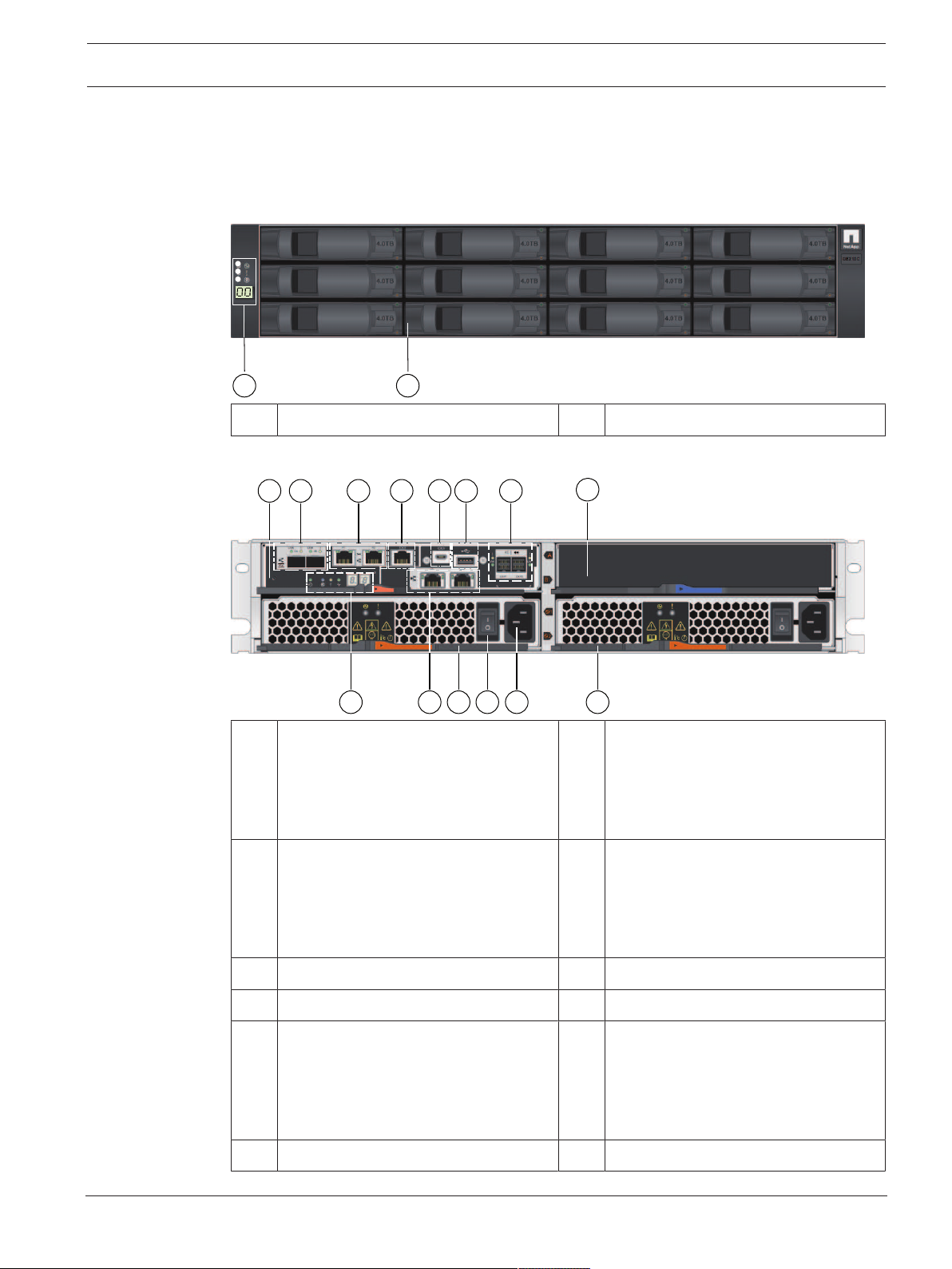
12-bay controller unit or expansion unit - front view
(Front view of the single controller unit, dual controller unit, or expansion unit)
1 Status displays 2 Drive canister
12-bay single controller unit - rear view
1 Controller canister 2 Channel3 (left) / Channel4 (right) -
Host interface ports (Dual 10GB
iSCSI, optical)
Note: Use only RJ45 Base‑T ports or
optical ports.
3 Management port1 (left) /
Management port2 (right) - Dual
1Gigabit Ethernet
Note: Use only Port1 per controller
(default).
5 Serial port (mini USB) 6 USB port (only for factory use)
7 Dual 12Gb SAS drive expansion ports 8 Empty
9 Status display 10 Channel5 (left) / Channel6 (right) -
11 Power-fan canister1 12 On/off switch
4 Serial port (RJ45)
Host interface ports (Dual 10GB
iSCSI, RJ45 Base‑T)
Note: Use only RJ45 Base‑T ports or
optical ports.
Bosch Sicherheitssysteme GmbH Installaton manual 2018.02 | V1 | DOC
Page 12
12 en | System overview DSA E-Series (E2800 12-bay)
1 5
9
2
6
3
7
4
8
1410 11 12 13
9 10
11 12 13 14
1 526374 8
13 Mains connection 100 - 240 VAC 14 Power-fan canister2
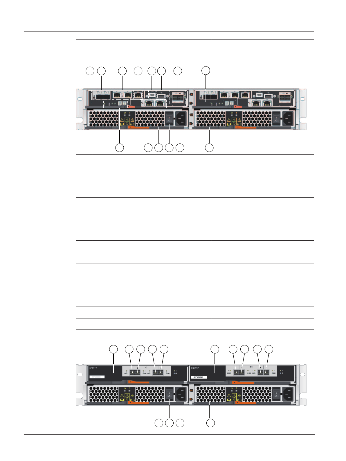
12-bay dual controller unit - rear view
1 ControllerA 2 Channel3 (left) / Channel4 (right) -
Host interface ports (Dual 10GB
iSCSI, optical)
Note: Use only RJ45 Base‑T ports or
optical ports.
3 Management port1 (left) /
4 Serial port (RJ45)
Management port2 (right) - Dual
1Gigabit Ethernet
Note: Use only Port1 per controller
(default).
5 Serial port (mini USB) 6 USB port (only for factory use)
7 Dual 12Gb SAS drive expansion ports 8 ControllerB (see ControllerA)
9 Status display 10 Channel5 (left) / Channel6 (right) -
Host interface ports (Dual 10GB
iSCSI, RJ45 Base‑T)
Note: Use only RJ45 Base‑T ports or
optical ports.
11 Power-fan canister1 12 On/off switch
13 Mains connection 100 - 240 VAC 14 Power-fan canister2
12-bay expansion unit - rear view
2018.02 | V1 | DOC Installaton manual Bosch Sicherheitssysteme GmbH
Page 13
DSA E-Series (E2800 12-bay) System overview | en 13
1
5
2
3
4
1 IOMA 2 IOMA - SAS port1
3 IOMA - SAS port2 4 IOMA - SAS port3
5 IOMA - SAS port4 6 IOMB
7 IOMB - SAS port1 8 IOMB - SAS port2
9 IOMB - SAS port3 10 IOMB - SAS port4
11 Power-fan canister1 12 On/off switch
13 Mains connection 100 - 240 VAC 14 Power-fan canister2
3.2 LED description
There are several LEDs on the front and rear of the chassis. The LEDs show the over-all status
of the system and the activity and health of specific components.
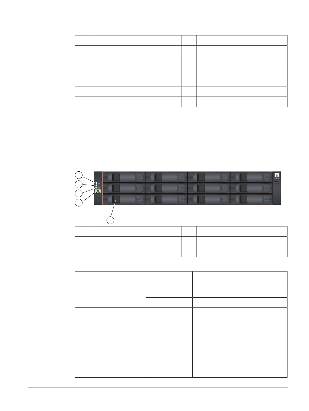
3.2.1 LEDs on the operator display panel
Each controller unit and expansion unit has LEDs located on the operator display panel. The
operator display panel is visible through the front bezel of a controller unit and through the
left end cap of an expansion unit.
1 Power LED 2 Attention LED
3 Locate LED 4 7-segment display
5 Drive canister
The following table describes the LEDs and their operational states:
LED Status indicator Description
Power Green One or more power supplies are
supplying power to the unit.
Off The unit is not receiving power.
Attention Amber There is an error with the function of
one or more of the following:
– Unit
– Drives
– IOMs
– Power supplies
– Fans
Off The unit, drives, IOMs, power supply,
and fans are functioning correctly.
Bosch Sicherheitssysteme GmbH Installaton manual 2018.02 | V1 | DOC
Page 14
14 en | System overview DSA E-Series (E2800 12-bay)
5 9
6
3 7
11
4 8
12
1
2
10
14
13
15
16
17
18
LED Status indicator Description
Locate Blue There is an active request to physically
locate the shelf.
Note: The Locate LED turns off
automatically after 30minutes.
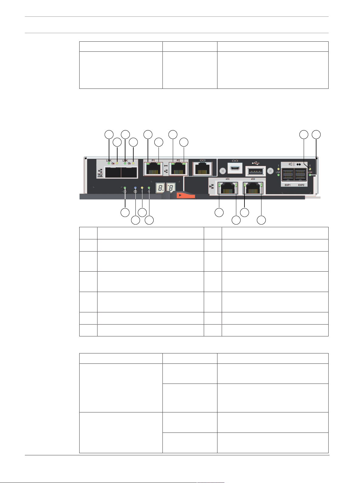
3.2.2 LEDs on the controller unit
The back of the controller unit includes LEDs that indicate the status of the controller. For
example, the controller is active, the controller needs attention, or when there is Ethernet
activity.
1 Channel3 - host port link status LED 2 Channel3 - host port attention LED
3 Channel4 - host port link status LED 4 Channel4 - host port attention LED
5 Management port1 - Ethernet status
LED
7 Management port2 - Ethernet status
LED
9 SAS drive expansion port - attention
LED
6 Management port1 - Ethernet activity
LED
8 Management port2 - Ethernet activity
LED
10 SAS drive expansion port - link status
LED
11 Cache active LED LED 12 Locate LED
13 Attention LED 14 Activity LED
The following table describes the LEDs and their operational states:
LED Status indicator Description
Cache active Green The cache contains data not yet written
to disk.
Off Either the cache is inactive or all data
from the cache has been preserved in
non-volatile memory.
Locate Blue There is an active request to physically
locate the controller unit.
Off There is no active request to locate the
controller unit.
2018.02 | V1 | DOC Installaton manual Bosch Sicherheitssysteme GmbH
Page 15

DSA E-Series (E2800 12-bay) System overview | en 15
LED Status indicator Description
Attention Amber The controller is faulty and requires
operator attention, and the faulty
component is serviceable.
Off The controller is operating normally.
Activity Blinking green The controller is active.
Ethernet activity (right) Green The link between the management port
and the device to which it is connected
(such as an Ethernet switch) is up.
Off There is no link between the controller
and the connected Ethernet port.
Blinking green There is Ethernet activity.
Ethernet link state (left) Green Link is established.
Off No link is established.
SAS expansion port link Green Link is established.
Off No link is established.
SAS expansion port link fault Amber Port is degraded (one or more physical
devices in the port are down).
Off Port is optimal. All physical devices in
the port are up or all physical devices in
the port are down since the LED is off if
no cables are attached.
Host port link status (SFP
host port, FC or iSCSI)
Green The link is up (Fibre channel).
LED is solid: The link is up, but there is
no activity (iSCSI).
LED is flashing: The link is up and there
is activity (iSCSI).
LED is off: The link is down.
Host port attention (SFP host
Amber The port requires operator attention.
port, FC or iSCSI)
Host port link status (RJ-45
host port, iSCSI)
Host port activity (RJ-45 host
port, iSCSI)
Green LED is on: The link is established.
LED is off: No link is established.
Green LED is on: The link is up with no activity.
LED is blinking: There is link activity.
LED is off: No link is established.
3.2.3 LEDs on the I/O modules
The I/O module (IOM) includes the SAS ports for connecting the expansion units to the
controller units or to other expansion units.
Bosch Sicherheitssysteme GmbH Installaton manual 2018.02 | V1 | DOC
Page 16

16 en | System overview DSA E-Series (E2800 12-bay)
1
2
3
4
1
2
1 SAS port attention LED 2 SAS port link LED
3 IOM attention LED 4 IOM locate LED
The following table describes the LEDs and their operational states:
LED Status indicator Description
Attention Amber The IOM is not functioning correctly.
Off The IOM is functioning correctly.
Locate Blue There is an active request to physically
locate the expansion unit.
Note: When the Locate LED is activated,
the Locate LED on the left end cap of
the expansion unit is also activated.
The Locate LEDs turn off automatically
after 30minutes.
Off There is no active request to locate the
expansion unit.
SAS port link Green The SAS port established a link (with
either a controller or another expansion
unit).
Off No link is established to another SAS
port.
SAS port attention Amber One or more of the links in the port are
not working properly.
Off The port is optimal and no link error has
occurred.
3.2.4 LEDs on the drives
The drives that are installed in the controller unit and the expansion unit include an Activity
LED and an Attention LED.
2018.02 | V1 | DOC Installaton manual Bosch Sicherheitssysteme GmbH
Page 17

DSA E-Series (E2800 12-bay) System overview | en 17
1
2
1 Activity LED 2 Attention LED
The following table describes the LEDs and their operational states:
LED Status indicator Description
Activity Green The drive has power.
Blinking green The drive has power, and I/O is in
process.
Attention Amber An error occurred with the functioning
of the drive.
3.2.5 LEDs on the power-fan canister
The power-fan canister has LEDs and its own power switch and power outlet. Each 12-bay
controller unit and 12-bay expansion unit has two of these canisters.
1 Power LED 2 Attention LED
The following table describes the LEDs and their operational states:
LED icon LED name Status indicator Description
Power Steady green The power supply is functioning
Attention Steady amber The power supply or its integrated fan
3.2.6 Seven-segment-display
Each controller unit has a two-digit, seven-segment display at the back, which shows the
controller state.
Controller state Seven-segment-display
correctly.
Off The power supply failed, the AC switch
is turned off, the AC power cord is not
properly installed, or the AC power cord
input voltage is not within margin (there
is a problem at the source end of the AC
power cord).
has a fault.
Functioning correctly Tray ID
Not functioning correctly Diagnostic codes to help identify errors.
Bosch Sicherheitssysteme GmbH Installaton manual 2018.02 | V1 | DOC
Page 18

18 en | System overview DSA E-Series (E2800 12-bay)
3
1
2
1 Tray ID 2 Heartbeat (dot in the lower right)
3 Diagnostic (dot in the upper left)
The following table describes the LEDs and their operational states:
LED Status indicator Description
Tray ID Green Shows the ID of the controller unit when
the controller operates normally. If the
controller is not operating normally and
the Diagnostic LED is on, the diagnostic
code is displayed instead.
Heartbeat Blinking green Indicates normal activity.
Diagnostic Green The seven-segment display shows the
diagnostic code.
Off The seven-segment display shows the
tray ID.
2018.02 | V1 | DOC Installaton manual Bosch Sicherheitssysteme GmbH
Page 19

DSA E-Series (E2800 12-bay) Installation | en 19
4 Installation
4.1 Installing a 2U 12-bay unit
You can install the unit in a four-post rack or system cabinet.
Observe the following:
– You can install the unit in either a square-hole or round-hole rack.
– If you are installing the unit in a cabinet not provided by Bosch, you must calculate the
thermal output of your equipment and compare the results with the target system
cabinet's thermal rating. You might need to remove the system cabinet doors to improve
airflow through the system cabinet.
For thermal rating information refer to the rack or system cabinet manuals provided by
the manufacturer.
– You must use only the screws that are provided in the kit.
Notice!
When installing the units, load the cabinet so as not to make it top-heavy. One approach is to
place the controller-unit in the middle portion of the cabinet while allowing room for
expansion units to be placed above and below the controller unit.
To install a 12-bay controller or expansion unit:
1. Determine where you want to install the unit in the rack or system cabinet.
Note: Whenever possible, install the units from the bottom of the rack up, so that you can
use the units underneath as a guide for installing the next set of rails.
2. Attach the rails to the rack or system cabinet as follows:
– Place the rail inside the rack or system cabinet where you want to install the unit.
Align the alignment screws on the rail with the holes on the front post of the rack.
– If you have a round-hole rack, remove the eight preinstalled square-hole rack
alignment screws and install the eight round-hole rack alignment screws.
Note: Ensure that you use the screws that are appropriate for your rack.
– Extend the rail to the back post of the rack or system cabinet until the flanges on the
rail touch the inside of the rack or system cabinet.
– Insert one M5 screw through the hole in the front of the rack or system cabinet, and
two M5 screws through the holes at the back of the rack or system cabinet.
– Repeat these steps for the other rail.
3. Place the back of the unit (the end with the connectors) on the rails.
Bosch Sicherheitssysteme GmbH Installaton manual 2018.02 | V1 | DOC
Page 20

20 en | Installation DSA E-Series (E2800 12-bay)
Caution: A fully loaded unit weighs approximately 65 lb (29 kg). Two persons or a
mechanical lift are required to safely move the unit.
4. Carefully slide the unit all the way onto the rails.
Note: If applicable, you might need to remove the end caps or the system bezel to secure
the unit to the rack post. Replace the end caps or bezel when you are done.
Note: You might need to adjust the rails to ensure that the unit slides all the way onto the
rails.
Note: Do not place additional equipment on the rails after you finish installing the unit.
The rails are not designed to bear additional weight.
5. Secure the unit to the front of the rack or system cabinet and rails by inserting two M5
screws through the mounting brackets (preinstalled on either side of the front of the
unit), the holes on the rack or system cabinet, and the holes on the front of rails.
2018.02 | V1 | DOC Installaton manual Bosch Sicherheitssysteme GmbH
Page 21

DSA E-Series (E2800 12-bay) Installation | en 21
6. Secure the unit to the back of the rails by inserting two M5 screws through the brackets
at the unit and the rail kit bracket.
7. If applicable, replace the end caps or the system bezel.
Note: Additional documentation can be found on the Bosch online catalog.
Notice!
Install the expansion units below and above the controller unit, keeping the weight in the
lower portion of the cabinet.
4.2 Installing the front bezel and end caps
A front bezel covers the front of the controller unit and the expansion unit, while left and right
end caps cover the mounting flanges on each unit.
To install the front bezel:
1. Position the front bezel in front of the controller unit or the expansion unit so that the
holes at each end align with the fasteners on the unit.
2. Snap the bezel into place.
To install the end caps:
1. Position the left end cap in front of the controller unit or the expansion unit so that the
holes in the end cap align with the fasteners on the left side of the unit.
2. Snap the end cap into place.
3. Repeat these steps for the right end cap.
4.3 Setting the unit ID using the ODP button
You can set or change the unit ID for a controller unit or a expansion unit by using the
operator display panel (ODP) button.
Before you begin
You might need to remove the front bezel or the end cap to see the ODP button.
Bosch Sicherheitssysteme GmbH Installaton manual 2018.02 | V1 | DOC
Page 22

22 en | Installation DSA E-Series (E2800 12-bay)
1
About this procedure
The following figure shows the operator display panel (ODP) button on the controller unit and
the expansion unit.
1 Operator display panel (ODP) button
To set the unit ID with the ODP button:
1. Turn on the unit.
2. Press and hold the ODP button until the first number on the seven-segment display starts
to blink.
Note: It can take up to three seconds for the number to blink. If the number does not
blink in this time, release the button and press it again. Make sure to press the button all
the way in.
3. Change the first number of the unit ID by repeatedly pressing the ODP button to advance
the number until you reach the desired number from 0 to 9.
The first number continues to blink.
4. Press and hold the ODP button until the second number on the digital display starts to
blink.
Note: It can take up to three seconds for the second number to blink. The first number on
the seven-segment display stops blinking.
5. Change the second number of the unit ID by repeatedly pressing the ODP button to
advance the number until you reach the desired number from 0 to 9.
The second number continues to blink.
6. Lock in the desired number, and exit the programming mode by pressing and holding the
ODP button until the second number stops blinking.
Note: It can take up to three seconds for the second number to stop blinking.
2018.02 | V1 | DOC Installaton manual Bosch Sicherheitssysteme GmbH
Page 23

DSA E-Series (E2800 12-bay) Connection | en 23
Controller A
IOM B
IOM A
Controller B
Controller A
IOM B
IOM A
Controller B
Controller A
IOM B
IOM A
IOM B
IOM A
IOM B
IOM A
5 Connection
5.1 Connecting the expansion units
The expansion units are shipped with the appropriate number of SAS cables.
To connect the components:
4 Connect the SAS cable from the SAS port on the controller unit to the SAS port on the
expansion unit.
One expansion unit - single controller configuration
One expansion unit - dual controller configuration
(recommended cabling for maximum throughput)
Three expansion units - dual controller configuration
Bosch Sicherheitssysteme GmbH Installaton manual 2018.02 | V1 | DOC
Page 24

24 en | Connection DSA E-Series (E2800 12-bay)
Controller B
Controller A
IOM B
IOM A
IOM B
IOM A
IOM B
IOM A
IOM B
IOM A
IOM B
IOM A
IOM B
IOM A
IOM B
IOM A
Maximum configuration - dual controller configuration
Notice!
You can connect a 12-bay DSAE2800 controller unit to a maximum of seven 12-bay
DSAE2800 expansion units.
5.2 Connecting the controller unit to the network
In case of a Bosch Video Recording Solution a host is an IP camera. To connect the controller
unit to the Ethernet one or two of two available iSCSI host ports must be connected to the
Ethernet. The iSCSI port connections will then be used by the IP cameras for video data
traffic.
2018.02 | V1 | DOC Installaton manual Bosch Sicherheitssysteme GmbH
Page 25

DSA E-Series (E2800 12-bay) Connection | en 25
2 3
1
To connect the controller unit to the network:
4 Connect the cable from the iSCSI host port of the controller unit to a port on the switch.
Note: Make sure that the iSCSI ports of the controller unit and the relevant IP camera
ports are in the same range on the switch.
Switch topology
1 Switch 2 Controller A - iSCSI host interface
ports (RJ45 Base‑T)
Note: Optionally, use the optical host
interface ports.
3 Controller B - iSCSI host ports (RJ45
Base‑T)
Note: Optionally, use the optical host
interface ports.
5.3 Connecting the controller unit to the management hosts
The management host directly manages storage arrays over an out-of-band network. This
section describes how to set up an out-of-band connection between the Ethernet port of a
controller unit and the management host.
To set up an out-of-band connection:
1. Connect Ethernet cables between port 1 of controller A and port 1 of controller B to an
external Ethernet switch or hub.
2. Connect the management host to the Ethernet switch or hub.
Bosch Sicherheitssysteme GmbH Installaton manual 2018.02 | V1 | DOC
Page 26

26 en | Connection DSA E-Series (E2800 12-bay)
1
5
2
3
7
4
6
98
1 Private network 2 Management station or personal
computer
3 Local Area Network (LAN) 4 Switch or hub
5 Dual controller unit 6 ControllerA
7 ControllerB 8 Management port1 (Ethernet)
Note: Used as default.
9 Management port2 (Ethernet)
Note: Reserved for maintenance
Notice!
Ethernet port 2 should be reserved for maintenance operations if your hardware contains a
second Ethernet port.
operations if the hardware contains a
second Ethernet port.
5.4 Connecting the units to the power supply
To connect the controller unit and the expansion units to the power supply:
1. Confirm that the two power switches on the controller unit are off.
Note: If you have expansion units, confirm that their power switches are off.
2018.02 | V1 | DOC Installaton manual Bosch Sicherheitssysteme GmbH
Page 27

DSA E-Series (E2800 12-bay) Connection | en 27
1
2. Connect the two power cords of the controller unit to different power distribution units
in the cabinet or rack.
Note: If you have expansion units, connect the two cords accordingly.
1 = Power switch
3. If you have expansion units, turn on their two power switches first.
Note: Wait for 2minutes to allow hard disks to spin up before applying power to the
controller unit.
4. Turn on the two power switches on the controller unit and wait approximately 3minutes.
Note:
– The default IP addresses will take approximately 3minutes to initialize from the time
the network is attached.
– Do not turn off the power switches during the power-on process.
– The fans are very loud when they first start up. The loud noise during start-up is
normal.
5. Check the LEDs and the seven-segment display on the back of each controller.
Note: The seven-segment display shows a repeating sequence (OS, Sd, blank) to indicate
that the controller is performing start-of-day processing. After the controller has started,
the display shows the tray ID.
6. If any of the amber LEDs are on, there might be a problem with a component. Confirm
you completed the installation steps correctly. If you are unable to resolve the problem,
contact your local Bosch Technical Support team.
5.5 Supported connections
We recommend using the following connection methods:
Bosch Sicherheitssysteme GmbH Installaton manual 2018.02 | V1 | DOC
Page 28

28 en | Connection DSA E-Series (E2800 12-bay)
LN K LN K
P1 P2
0b
0a
e0c e0d
LN K LN K
P1 P2
0b
0a
e0c e0d
LN K
LN K
P1 P2
0b
0a
e0c
e0d
LN K
LN K
P1 P2
0b
0a
e0c e0d
1
23 4
5
6
Controller A
LN K LN K
P1 P2
0b
0a
e0c e0d
LN K LN K
P1 P2
0b
0a
e0c e0d
LN K
LN K
P1 P2
0b
0a
e0c e0d
LN K
LN K
P1 P2
0b
0a
e0c e0d
Controller BController A
1
23 4
5
6
1
23 4
5
6
12-bay single controller unit
1 Management port1 (Ethernet)
Note: Used as default.
2 Management port 2 (Ethernet)
Note: Reserved for maintenance
operations if the hardware contains a
second Ethernet port.
3 Channel3 (iSCSI, optical) 4 Channel4 (iSCSI, optical)
5 Channel5 (iSCSI, RJ45 Base‑T) 6 Channel6 (iSCSI, RJ45 Base‑T)
Single controller units support 2different cabling options for the iSCSI ports.
– Default: iSCSI, RJ45 Base‑T
– Alternatively: iSCSI, optical
12-bay dual controller unit
2018.02 | V1 | DOC Installaton manual Bosch Sicherheitssysteme GmbH
1 Management port1 (Ethernet)
Note: Used as default.
3 Channel3 / ControllerA and
Channel3 / ControllerB (iSCSI,
optical)
2 Management port 2 (Ethernet)
Note: Reserved for maintenance
operations if the hardware contains a
second Ethernet port.
4 Channel4 / ControllerA and
Channel4 / ControllerB (iSCSI,
optical)
Page 29

DSA E-Series (E2800 12-bay) Connection | en 29
5 Channel5 / ControllerA and
Channel5 / ControllerB (iSCSI, RJ45
Base‑T)
6 Channel6 / ControllerA and
Channel6 / ControllerB (iSCSI, RJ45
Base‑T)
The Multipathing feature is enabled on dual controller units by default.
Dual controller units support 2different cabling options for the iSCSI ports.
– Default: iSCSI, RJ45 Base‑T
Note:
– Channel5 / ControllerB is the fallback of Channel5 / ControllerA and
Channel 6 / ControllerA is the fallback of Channel6 /. ControllerB
– Alternatively: iSCSI, optical
Note:
– Channel3 / ControllerB is the fallback of Channel3 / ControllerA and
Channel 4 / ControllerA is the fallback of Channel4 /. ControllerB
Bosch Sicherheitssysteme GmbH Installaton manual 2018.02 | V1 | DOC
Page 30

30 en | Turning on/off AC power DSA E-Series (E2800 12-bay)
6 Turning on/off AC power
6.1 Turning on AC power
Make sure the Ethernet cable is connected to the management host. The default IP addresses
will take three minutes to initialize from the time the network is attached.
The default IP addresses are:
– Controller A, Port 1: 192.168.128.101
– Controller B, Port 1: 192.168.128.102
Notice!
DHCP is attempted for the first three minutes of attaching the network cables. If a DHCP
lease was not offered within this time, the controllers will use the default addresses.
To turn on power to the controller unit or the expansion units:
1. Connect the cabinet to the power supply.
2. Turn on the power distribution units of the cabinet.
3. If you have expansion units, turn on their two power switches first.
Note: Wait for 2minutes to allow hard disks to spin up before applying power to the
controller unit.
4. Turn on the two power switches on the controller unit and wait approximately 3minutes.
Note:
– The default IP addresses will take approximately 3minutes to initialize from the time
the network is attached.
– Do not turn off the power switches during the power-on process.
– The fans are very loud when they first start up. The loud noise during start-up is
normal.
5. Check the LEDs and the seven-segment display on the back of each controller.
Note: The seven-segment display shows a repeating sequence (OS, Sd, blank) to indicate
that the controller is performing start-of-day processing. After the controller has started,
the display shows the tray ID.
6. If any of the amber LEDs are on, there might be a problem with a component. Confirm
you completed the installation steps correctly. If you are unable to resolve the problem,
contact your local Bosch Technical Support team.
7. Connect all cables if required.
8. Start recording of the cameras.
6.2 Turning off AC power
We recommend turning off the system when moving the system to another location and
upgrading or replacing the hardware, for example.
To turn off power to the controller unit or the expansion units:
1. Stop recording of the cameras and wait for 5minutes.
2. Ensure there are no background operations in progress.
3. Turn off the controller-unit and wait that all LEDs are off.
4. Turn off the expansion units and wait for 2minutes to allow hard disks to spin down.
5. Disconnect the cables if required.
2018.02 | V1 | DOC Installaton manual Bosch Sicherheitssysteme GmbH
Page 31

DSA E-Series (E2800 12-bay) Configuring the storage system | en 31
7 Configuring the storage system
This chapter describes the basic configuration of the storage system using the Configuration
Manager program.
To create a basic configuration:
1. Start the Configuration Manager program.
2. On the toolbar, click the Devices tab, right-click the corresponding device in the tree
structure, then click Add to System....
The Add Device to System dialog box is displayed.
3. Select an existing group to assign the device or leave the field empty if you do not want
to assign the device to a group.
4. Click OK. The device is added to the system.
5. On the toolbar, click the My Devices tab.
6. In the device tree, click the corresponding device, click Pool x, click Storage Systems,
then click the storage system.
7. In the view pane, click the Basic configuration tab. The basic configuration settings of the
storage system are displayed.
8. Enter the basic settings of your storage system.
9. Click Initialize. An information message box is displayed.
10. Click Yes to confirm that you want to proceed with the basic configuration. The Basic
Configuration for the iSCSI system dialog box is displayed. The dialog box shows the
status of the configuration process.
11. Click the Status tab to display the status of the configuration process.
Click the Details tab to display details about all processes.
Click Close to close the dialog box.
12. Click the Reload page icon.
13. In the device tree, right-click the storage system, then click LUN Assignment…. The LUN
Assignment dialog box is displayed.
Note: If multiple iSCSI ports are used, distribute the LUNs equally among the logical
iSCSI targets. Do not assign one LUN to multiple logical iSCSI targets.
14. Drag the Target x folder from the left side (Source) to the right side (VRM System), then
click OK.
15. In the device tree, below the storage system, click Target x. All assigned LUNs are
displayed with the status Unformatted.
16. In the view pane, click Select All, then click Set. The LUNs are displayed with the status
Task format and a warning message box is displayed that informs you that formatting a
disk will erase all data.
17. Click Yes to confirm. The status of the LUNs changes to Ready. The LUNs are formatted.
Bosch Sicherheitssysteme GmbH Installaton manual 2018.02 | V1 | DOC
Page 32

32 en | Maintenance DSA E-Series (E2800 12-bay)
1
5
9
2
6
10
3
7
11
4
8
0
8 Maintenance
8.1 Replacing a drive in a 12-bay unit
The Recovery Guru in SANtricity System Manager monitors the drives in the unit and can notify
you of an impending drive failure or an actual drive failure. When a drive has failed, its amber
Attention LED is on. You can hot-swap a failed drive while the unit is receiving I/O operations.
Before you begin
– You have a replacement drive that is supported by Bosch for the controller unit or
expansion unit.
– You have an ESD wristband, or you have taken other antistatic precautions.
About this procedure
Use this procedure to replace a drive in the following controller units or expansion units:
Type Number of drives Type of drives
12-bay controller unit 12 3.5-inch SAS drives (or 2.5-inch SAS drives in
12-bay expansion unit 12
Drive numbering in a 12-bay controller unit or a 12-bay expansion unit
carriers)
Rules for handling drives
The drives are fragile. Improper drive handling is a leading cause of drive failure. Follow these
rules to avoid damaging the drives in your unit:
– Prevent electrostatic discharge (ESD)
– Keep the drive in the ESD bag until you are ready to install it.
– Do not insert a metal tool or knife into the ESD bag. Open the ESD bag by hand or
cut the top off with a pair of scissors.
– Keep the ESD bag and any packing materials in case you must return a drive later.
– Always wear an ESD wrist strap grounded to an unpainted surface on your storage
enclosure chassis. If a wrist strap is unavailable, touch an unpainted surface on your
storage enclosure chassis before handling the drive.
– Handle drives carefully
– Always use two hands when removing, installing, or carrying a drive.
– Never force a drive into a unit. Use gentle, firm pressure to completely engage the
drive latch.
– Place drives on cushioned surfaces, and never stack drives on top of each other.
– Do not bump drives against other surfaces.
– Before removing a drive, unlatch the handle and wait 30seconds for the drive to spin
down.
– Always use approved packaging when shipping drives.
– Avoid magnetic fields
– Keep drives away from magnetic devices. Magnetic fields can destroy all data on the
drive and cause irreparable damage to the drive circuitry.
To replace a drive observe the instructions in the following chapters:
1. Preparing to replace a drive, page 33
2018.02 | V1 | DOC Installaton manual Bosch Sicherheitssysteme GmbH
Page 33

DSA E-Series (E2800 12-bay) Maintenance | en 33
1
2
2. Removing a drive, page 33
3. Installing a drive, page 34
4. After replacing a drive, page 34
8.1.1 Preparing to replace a drive
Before replacing a drive, check the Recovery Guru in SANtricity System Manager and complete
any prerequisite steps. Then, you can locate the failed drive.
To locate the failed drive:
1. If the Recovery Guru in SANtricity System Manager has notified you of an impending drive
failure, but the drive has not yet failed, follow the instructions in the Recovery Guru to fail
the drive.
2. If needed, use SANtricity System Manager to confirm you have a suitable replacement
drive.
– Select Hardware.
– Select the failed drive on the unit graphic.
– Click the drive to display the context menu, then select View settings.
– Confirm that the replacement drive has a capacity equal to or greater than the drive
you are replacing and that it has the features you expect.
For example, do not attempt to replace a hard disk drive (HDD) with a solid-state
disk (SSD). Similarly, if you are replacing a secure-capable drive, make sure the
replacement drive is also secure-capable.
3. If needed, use SANtricity System Manager to locate the drive within the storage unit.
– If the unit has a bezel, remove it so you can see the LEDs.
– From the drive's context menu, select Turn on locator light.
The drive's amber Attention LED blinks so you can identify which drive to replace.
1 Activity LED 2 Attention LED
8.1.2 Removing a drive
When removing a drive from a 12-bay controller unit or a 12-bay expansion unit, you must slide
the drive partly out of the unit and wait for the drive to spin down. Then, you can remove the
drive completely.
Before you begin:
– You have an ESD wristband, or you have taken other antistatic precautions.
– You have reviewed the .
To remove a drive:
1. Unpack the replacement drive, and set it on a flat, static-free surface near the unit. Save
all packing materials for the next time you need to send a drive back.
2. Press the release button on the failed drive. The release button is located at the left of
the drive.
The cam handle on the drive springs open partially, and the drive releases from the
midplane.
Bosch Sicherheitssysteme GmbH Installaton manual 2018.02 | V1 | DOC
Page 34

34 en | Maintenance DSA E-Series (E2800 12-bay)
6.0TB
6.0TB
6.0TB
3. Open the cam handle, and slide out the drive slightly.
4. Wait 30seconds.
5. Using both hands, remove the drive from the unit.
6. Place the drive on an antistatic, cushioned surface away from magnetic fields.
7. Wait 30seconds for the software to recognize that the drive has been removed.
Notice!
If you accidentally remove an active drive, wait at least 30seconds, and then reinstall it. For
the recovery procedure, refer to the storage management software.
8.1.3 Installing a drive
Install the replacement drive as soon as possible after removing the failed drive. Otherwise,
there is a risk that the equipment might overheat.
To install a drive:
1. Open the cam handle.
2. Using two hands, insert the replacement drive into the open bay, firmly pushing until the
drive stops.
3. Slowly close the cam handle until the drive is fully seated in the midplane and the handle
clicks into place.
Note: Depending on your configuration, the controller might automatically reconstruct
data to the new drive. If the unit uses hot spare drives, the controller might need to
perform a complete reconstruction on the hot spare before it can copy the data to the
replaced drive. This reconstruction process increases the time that is required to
complete this procedure.
8.1.4 After replacing a drive
After replacing a drive, you must confirm that the new drive is working correctly.
To confirm that the drive is working correctly:
1. Check the Power LED and the Attention LED on the drive you replaced.
LED status Description
The Power LED is on or blinking, and the
Attention LED is off.
The Power LED is off. The drive might not be installed correctly.
The Attention LED is on. The new drive might be defective. Replace it
2018.02 | V1 | DOC Installaton manual Bosch Sicherheitssysteme GmbH
The new drive is working correctly
Remove the drive, wait 30seconds, and then
reinstall it.
with another new drive.
Note: When you first insert a drive, its
Attention LED might be on. However, the LED
should go off within a minute.
Page 35

DSA E-Series (E2800 12-bay) Maintenance | en 35
1
1
2. If the Recovery Guru in SANtricity System Manager still shows an issue, select Recheck to
ensure the problem has been resolved.
3. If the Recovery Guru indicates that drive reconstruction did not start automatically, start
reconstruction manually, as follows:
Note: Perform this operation only when instructed to do so by technical support or the
Recovery Guru.
– Select Hardware.
– Click the drive that you replaced.
– From the drive's context menu, select Reconstruct.
– Confirm that you want to perform this operation.
When the drive reconstruction completes, the volume group is in an optimal state.
4. As required, reinstall the bezel on the front of the unit.
5. Return the failed part to Bosch, as described in the RMA instructions shipped with the
kit.
8.2 Replacing a power-fan canister
Each 12-bay controller unit or 12-bay expansion unit includes 2power supplies with integrated
fans. These are referred to as power-fan canisters in SANtricity System Manager. If a powerfan canister fails, you must replace it as soon as possible to ensure that the unit has a
redundant power source and adequate cooling.
Before you begin
– You have a replacement power-fan canister (power supply) that is supported for your 12-
bay controller unit or 12-bay expansion unit.
– You have an ESD wristband, or you have taken other antistatic precautions.
About this procedure
Use this procedure to replace a power-fan canister in the following shelves:
– 12-bay controller unit
– 12-bay expansion unit
12-bay dual controller unit - rear view
1 Power-fan canisters
12-bay expansion unit - rear view
Bosch Sicherheitssysteme GmbH Installaton manual 2018.02 | V1 | DOC
Page 36

36 en | Maintenance DSA E-Series (E2800 12-bay)
1 Power-fan canisters
You can replace a power-fan canister while the unit is turned on and performing host I/O
operations, as long as the following conditions are true:
– The second power-fan canister in the unit has an Optimal status.
– The OK to remove field in the Details area of the Recovery Guru in SANtricity System
Manager displays Yes, indicating that it is safe to remove this component.
Note: If the second power-fan canister in the shelf does not have Optimal status or if the
Recovery Guru indicates that it is not OK to remove the power-fan canister, contact
technical support.
To replace a power-fan canister observe the instructions in the following chapters:
Preparing to remove a power-fan canister, page 36
Removing a power-fan canister, page 37
Installing a power-fan canister, page 38
After replacing a power-fan canister, page 38
8.2.1 Preparing to remove a power-fan canister
Before removing a power-fan canister, use SANtricity System Manager to collect support data
about your storage system and to locate the failed component.
You can determine if you have a failed power-fan canister in these ways:
– The Recovery Guru in SANtricity System Manager directs you to replace a failed power-fan
canister.
Note: Before replacing a power-fan canister, select Recheck from the Recovery Guru to
ensure no other items must be addressed first.
– The amber Attention LED on the power-fan canister is on, indicating that the power
supply or its integrated fan is faulty.
Note: If both power-fan canisters in the unit have their Attention LEDs on, contact
technical support for assistance.
To prepare the removing of the component:
1. Collect support data for your storage system (see Collecting support data for the storage
system, page 43).
Note: Collecting support data before and after replacing a component ensures you can
send a full set of logs to technical support in case the replacement does not resolve the
problem.
2. From SANtricity System Manager, determine which power-fan canister has failed. You can
find this information in the Details area of the Recovery Guru, or you can review the
information displayed for the shelf.
– Select Hardware.
– Look at the power icon and fan icon to the right of the Shelf drop-down
lists to determine which shelf has the failed power-fan canister.
If a component has failed, either or both of these icons will be red.
– When you find the shelf with a red icon, select Show back of shelf.
– Select the power-fan canister.
– On the Power Supplies and Fans tabs, look at the statuses of the power-fan
canisters, the power supplies, and the fans to determine which power-fan canister
must be replaced.
A component with a Failed status must be replaced.
2018.02 | V1 | DOC Installaton manual Bosch Sicherheitssysteme GmbH
Page 37

DSA E-Series (E2800 12-bay) Maintenance | en 37
X
2
2
Note: If the second power-fan canister in the shelf does not have Optimal status, do
not attempt to hot-swap the failed power-fan canister. Instead, contact technical
support for assistance.
3. From the back of the storage array, look at the Attention LEDs to locate the power-fan
canister you need to remove. You must replace the power-fan canister that has its
Attention LED on.
See also
– LEDs on the power-fan canister, page 17
8.2.2 Removing a power-fan canister
When you remove a power supply (referred to in SANtricity System Manager as a power-fan
canister), you turn off power, disconnect the power cord, and slide the part out of the shelf.
To remove a power-fan canister:
1. Put on antistatic protection.
2. Unpack the new power supply, and set it on a level surface near the drive shelf.
Save all packing materials for use when returning the failed power supply.
3. Turn off the power supply and disconnect the power cables:
– Turn off the power switch on the power supply.
– Open the power cord retainer, and then unplug the power cord from the power
supply.
– Unplug the power cord from the power source.
4. Squeeze the latch on the power supply cam handle, and then open the cam handle to
fully release the power supply from the midplane.
5. Use the cam handle to slide the power supply out of the system.
As you remove the power supply, a flap swings into place to block the empty bay, helping
to maintain air flow and cooling.
Note: When removing a power supply, always use two hands to support its weight.
Bosch Sicherheitssysteme GmbH Installaton manual 2018.02 | V1 | DOC
Page 38

38 en | Maintenance DSA E-Series (E2800 12-bay)
8.2.3 Installing a power-fan canister
To install a power-fan canister:
1. Make sure that the on/off switch of the new power supply is in the Off position.
2. Using both hands, support and align the edges of the power supply with the opening in
the system chassis, and then gently push the power supply into the chassis using the cam
handle.
The power supplies are keyed and can only be installed one way.
Note: Do not use excessive force when sliding the power supply into the system; you can
damage the connector.
3. Close the cam handle so that the latch clicks into the locked position and the power
supply is fully seated.
4. Reconnect the power supply cabling as follows:
Reconnect the power cord to the power supply and the power source.
Secure the power cord to the power supply using the power cord retainer.
5. Turn on the power to the new power-fan canister.
8.2.4 After replacing a power-fan canister
After replacing a power-fan canister, you must confirm that the new power-fan canister is
working correctly. Then, you can gather support data and resume operations.
To confirm that the power-fan canister is working correctly:
1. Check the green Power LED and the amber Attention LED on the new power-fan canister.
The green LED should be on and the amber LED should be off (see LEDs on the power-fan
canister, page 17).
2. From the Recovery Guru in SANtricity System Manager, select Recheck to ensure the
problem has been resolved.
3. If a failed power-fan canister is still being reported, repeat the steps in the following
sections:
– Removing a power-fan canister, page 37
– Installing a power-fan canister, page 38.
If the problem continues to persist, contact technical support.
4. Remove the antistatic protection.
5. Collect support data for your storage system (see Collecting support data for the storage
system, page 43).
Note: Collecting support data before and after replacing a component ensures you can
send a full set of logs to technical support in case the replacement does not resolve the
problem.
8.3 Seven-segment display codes
The following chapters explain the codes that are displayed on the seven-segment-display.
– Seven-segment display sequence codes, page 39
– Seven-segment display codes when controller turns on, page 40
– Seven-segment display use cases, page 40
– Seven-segment display lock-down codes, page 41
2018.02 | V1 | DOC Installaton manual Bosch Sicherheitssysteme GmbH
Page 39

DSA E-Series (E2800 12-bay) Maintenance | en 39
8.3.1 Seven-segment display sequence codes
Seven-segment display sequences enable you to understand errors and operational states of
the various components in your storage array. Each sequence shows a two-digit category
code, followed by a two-digit detail code. The category code appears at the start of a
sequence and the detail code follows the category code with more specific information about
the error. After each category code is displayed, the LED goes blank. Then the detail code
appears and disappears, and the entire sequence is repeated. For example, if there is a
power-on validation error during startup, you see the following codes displayed on the sevensegment display: SE, followed by Sx, in which SE is the category code and Sx is the detail
code.
When the seven-segment display sequence starts, the Diagnostic LED is on (green).
The following table includes the seven-segment display sequence codes and descriptions:
Category Category code Detail code
Startup error SE – 88: Power-on default
– dF: Power-on diagnostic fault
– Sx: Power-on validation error
Operational error OE – Lx: Lock-down codes
See Seven-segment display lock-down
codes.
Operational state OS – OL: Offline
– bb: Battery backup (operating on
batteries)
– OH: CPU temperature exceeds the
warning level
– CF: Component failure
Component failure CF – dx: Processor or cache DIMM
– Cx: Cache DIMM
– Px: Processor DIMM
– Hx: Host interface card
– Fx : Flash drive
– bl: Base controller card
Diagnostic failure dE – Lx: Lock-down codes
– See Seven-segment display lock-
down codes.
Category delimiter --
Note: The double
hyphen (--) is the
separator between
categorydetail
code pairs when
more than one pair
exists in the
sequence.
End-of-sequence delimiter Blank: The display
turns off at the end
of a sequence.
Bosch Sicherheitssysteme GmbH Installaton manual 2018.02 | V1 | DOC
Page 40

40 en | Maintenance DSA E-Series (E2800 12-bay)
8.3.2 Seven-segment display codes when controller turns on
The following table describes the seven-segment codes that are displayed when the controller
turns on:
Code Description
0xEA DDR4 training failed
0xE8 No memory installed
0x22 No master boot record found on any boot
device
0x23 No SATA drive installed
0xAE Booting OS
0xAB Alternate boot code
0x40 Invalid DIMMs
0x41 Invalid DIMMs
0x42 Memory test failed
0x2A, 0x2B Stuck bus, unable to read DIMM SPD data
0x51 DIMM SPD read failure
0xA0, 0xA1, 0xA2, and 0xA3 SATA drive initialization
0x92 - 0x96 PCI bus initialization
8.3.3 Seven-segment display use cases
The following table shows seven-segment display use cases and the sequence that is
displayed in each case:
Use case Display sequence
Controller power-on
– Normal power-on controller insertion SE 88 blank
– Controller inserted while held in reset
Operational states
Normal operation xy (static controller tray ID)
Start-of-day (SOD) processing OS Sd blank
The controller is placed in reset while
showing the tray ID
OS OL blank
The controller is operating on batteries
(cache backup)
The CPU temperature has exceeded the
warning level
Component failure when the controller is operational
Failed host interface card (HIC) OS CF HX blank
2018.02 | V1 | DOC Installaton manual Bosch Sicherheitssysteme GmbH
OS bb blank
OS OH blank
Page 41

DSA E-Series (E2800 12-bay) Maintenance | en 41
Use case Display sequence
Failed flash drive OS CF Fx blank
Power-on diagnostic failure
Failure of a component that is not a field
SE dF blank-
replaceable unit
Processor DIMM failure SE dF -- CF Px blank-
Cache memory DIMM failure SE dF -- CF Cx blank-
Processor DIMM or cache memory DIMM
SE dF -- CF dx blank-
failure
Host interface card failure SE dF -- CF Hx blank-
Incorrect number of cache backup devices SE LC -- CF Fx blank-
The controller is suspended and there are no other errors to report
All lock-down conditions OH Lx blank
The controller is suspended because of component errors
Persistent processor DIMM error correcting
OE L2 -- CF Px blank-
code (ECC) errors
Persistent cache DIMM ECC errors OE L2 -- CF Cx blank-
Persistent processor or cache DIMM ECC
OE L2 -- CF dx blank-
errors
The controller is suspended as a result of persistent cache backup configuration errors
The write-protect switch is set during cache
OE LC blank-
restore
The memory size changed with dirty data in
OE L2 -- CF dx blank-
the flash drives
The controller is suspended as a result of diagnostic errors
Cache memory diagnostic failure dE L2 -- CF Cx blank-
Base controller diagnostic failure dE L3 -- CF b1 blank-
Base controller I/O Controller chip (IOC)
dE L3 -- CF b2 blank-
diagnostic failure
8.3.4 Seven-segment display lock-down codes
Diagnostic lock-down codes are displayed when the controller is not operational, either
because of a configuration problem or a hardware fault. The lock-down code is displayed as
part of the seven-segment display sequence.
The following table includes the lock-down codes and describes the conditions that cause the
controller to be in a suspended state:
Lock-down code Description
L0 The controller types in a duplex configuration
are mismatched.
Bosch Sicherheitssysteme GmbH Installaton manual 2018.02 | V1 | DOC
Page 42

42 en | Maintenance DSA E-Series (E2800 12-bay)
Lock-down code Description
L1 Missing interconnect canister.
L2 A persistent memory error has occurred.
L3 A persistent hardware error has occurred.
L4 A persistent data protection error has
occurred.
L5 An auto-code synchronization (ACS) failure
has been detected.
L6 An unsupported HIC has been detected.
L7 A sub-model identifier either has not been set
or has been mismatched.
L8 A memory configuration error has occurred.
L9 A link speed mismatch condition has been
detected in either the I/O module (IOM) or
the power supply.
Lb A HIC configuration error has been detected.
LC A persistent cache backup configuration error
has been detected.
Ld A mixed cache memory DIMMs condition has
been detected.
LE Uncertified cache memory DIMM sizes have
been detected.
LF The controller has locked down in a
suspended state with limited SYMbol
support.
LH A controller firmware mismatch has been
detected.
LJ The controller does not have enough memory
to support the configuration.
LL The controller cannot access either midplane
SBB EEPROM.
Ln A module is not valid for a controller.
LP Drive port mapping tables are not detected.
Lr A component that is not a field replaceable
unit (FRU) has been replaced.
Lt A configuration data base corruption has
been detected.
LU The SOD reboot limit has been exceeded.
In some cases, controllers detect errors during the startup process.
2018.02 | V1 | DOC Installaton manual Bosch Sicherheitssysteme GmbH
Page 43

DSA E-Series (E2800 12-bay) Maintenance | en 43
The following table describes seven-segment startup errors and conditions that result in the
controller being in a suspended state:
Startup error code Description
S1 The controller detects a checksum failure in
EEPROM.
S2 The SBB Signature/Revision is invalid.
S3 An unsupported enclosure is detected in the
storage array.
S4 The power supplies are incapable of
powering the controller.
S5 The SBB pairing has failed.
8.4 Collecting support data for the storage system
The following procedures describe how to collect support data for the storage system using
SANtricity System Manager and Script editor in the Enterprise Management Window (EMW).
Collecting support data using SANtricity System Manager
1. Select Support > Support Center > Diagnostics.
2. Select Collect Support Data.
3. Click Collect.
The file is saved in the Downloads folder for your browser with the name
supportdata.7z
Collecting support data using Script editor in the EMW
1. Open the Enterprise Management Window (EMW) in SANtricity Storage Manager on your
local host.
2. Select the storage system.
3. Select Tools > Execute Script.
4. Type the following command in the text box.
save storageArray supportData file="filename";
In this command, filename is the file path and the file name to which you want to save
the support data. Enclose the file path and the file name in double quotation marks (" ").
For example:
file="C:\Program Files\CLI\logs\support-data.7z"
5. Select Tools > Verify and Execute
Bosch Sicherheitssysteme GmbH Installaton manual 2018.02 | V1 | DOC
Page 44

Page 45

Page 46

Page 47

Page 48

Bosch Sicherheitssysteme GmbH
Robert-Bosch-Ring 5
85630 Grasbrunn
Germany
www.boschsecurity.com
© Bosch Sicherheitssysteme GmbH, 2018
 Loading...