

Bosch DSA-N2B20, DSA-N2B50, DSA-N2B40 Installation Instructions Manual

DSDA Digital Storage Disk Arrays
DSA-N2B20 | DSA-N2B40 | DSA-N2B50
en Installation Guide


DSDA Digital Storage Disk Arrays Table of Contents | en 3
Bosch Sicherheitssysteme GmbH Installation Guide - | V2 | 2009.11
Table of Contents
1Precautions 5
2 Introduction 6
2.1 Systems at a Glance 6
2.1.1 Hardware Overview 6
2.1.2 CCTV Integration 7
3 Delivery Status 8
4 Unpacking and Installing the Hardware 9
5 Connecting the hardware 10
6 Configuration through the Web Interface 11
6.1 Configuration of the Network Settings and Access to the Interface 11
6.2 Time and Date Settings 14
6.3 Configuring the Volume 15
6.4 Creating an Initiator Group 17
6.5 Creating LUNs 17
7 Adding Storage 20
7.1 Installing a Shelf 20
7.1.1 Setting the Shelf ID 20
7.1.2 Connecting the Power Supplies 21
7.1.3 Connecting the Shelf 22
7.1.4 Adding New Volumes 22
7.1.5 Creating LUNs 25
8 Monitoring and Maintenance 26
8.1 Monitoring the System 26
8.1.1 Using the FilerView Monitor 26
8.1.2 Logs and Reports 26
8.2 Maintenance 27
8.2.1 Disk Replacement DSA-N2B20 / DSA-N2B40 / DSA-N2B50 27
8.2.2 Replacement of Modules 27
8.3 Hardware Troubleshooting 28
8.3.1 DSA-N2B20 / DSA-N2B40 / DSA-N2B50 28
8.3.2 Disk Shelves 28
8.4 Software Update 29
8.5 Disk Identification 31
8.5.1 DSA-N2B20 / DSA-N2B40 / DSA-N2B50 31
8.5.2 Disk Shelf 31

4 en | Table of Contents DSDA Digital Storage Disk Arrays
- | V2 | 2009.11 Installation Guide Bosch Sicherheitssysteme GmbH
9 Technical Data 32
9.1 Electrical Specifications 32
9.1.1 One Controller Module - DSA-N2B20 32
9.1.2 One Controller Module - DSA-N2B40 32
9.1.3 One Controller Module - DSA-N2B50 32
9.1.4 Disk Shelf Expansion Unit - DSX-N2X00-14AT 33
9.2 Mechanical Specifications 33
9.2.1 System Hardware Specifications - DSA-N2B20 33
9.2.2 System Hardware Specifications - DSA-N2B40 33
9.2.3 System Hardware Specifications - DSA-N2B50 33
9.2.4 System Hardware Specifications - DSX-N2X00-14AT 34
9.2.5 Mechanical - DSA-N2B20/DSA-N2B40 34
9.2.6 Mechanical - DSA-N2B50 34
9.2.7 Mechanical Disk Shelf Expansion Unit - DSX-N2X00-14AT 34
9.2.8 Space Requirements - DSA-N2B20/DSA-N2B40 34
9.2.9 Space Requirements - DSA-N2B50 34
9.2.10 Space Requirements Disk Shelf Expansion Unit - DSX-N2X00-14AT 34
9.3 Environmental Specifications 35
9.3.1 Environmental - DSA-N2B20/DSA-N2B40 35
9.3.2 Environmental - DSA-N2B50 35
9.3.3 Environmental Disk Shelf Expansion Unit - DSX-N2X00-14AT 35

DSDA Digital Storage Disk Arrays Precautions | en 5
Bosch Sicherheitssysteme GmbH Installation Guide - | V2 | 2009.11
1 Precautions
– The system is heavy even without disks installed. At least two people are required to
install the system.
– The rack cabinet into which this system will be installed must support overcurrent
protection and must not be overloaded by the modules installed. Other requirements,
such as ventilation airflow, rack stabilizing features, electrical earth, and electrical
distribution, must comply with the technical specifications listed in Section 9 Technical
Data, page 32 and in the documentation that came with this product.
– All systems must be mounted with and supported by the rails provided and secured in
position by the four screws in the front side flanges. In no instance is a system to be
mounted by the front side flanges only as this will result in the deforming of the systems
chassis causing unacceptably high pressures and/or torques to be applied to internal
components resulting in various failure modes.
– System Integrators should ensure that any integrated storage solution that includes this
product has been tested and proved to meet government regulations and codes for
subjects including safety, fire, and electrical.
– Make sure you have a soft, clean surface to place your system before working on it.
Placing the system on a rough surface during servicing may damage the chassis finish.
– Do not remove any module or component item from its anti-static bag until you are ready
to install it. Pick up and hold modules by their edges or canister. Avoid touching PCBs
and connector pins.
– Observe all standard ESD prevention methods, e.g., wear an anti-static wristband to
prevent static electricity from damaging the electric components.
– When replacing components insert them as gently as possible while assuring full
engagement. Vibration or shock can damage hard drives in the affected unit or other
units in the rack. Hard drives are very sensitive to shock and vibration, especially while in
operation and should always be handled very carefully.
– After all equipment is installed in a rack dress the power and data cables such that power
cables are not resting against data (SCSI, IP, RS-232) cables.
6 en | Introduction DSDA Digital Storage Disk Arrays
- | V2 | 2009.11 Installation Guide Bosch Sicherheitssysteme GmbH
2 Introduction
This guide explains the installation of the digital storage systems of type
– DSA-N2B20
– DSA-N2B40
– DSA-N2B50
for either direct storage of recorded video data or for use with the VRM Video Recording
Manager application.
Additional documentation is available on the Internet and can be downloaded from
www.boschsecurity.com under Product Catalog > CCTV > Digital Recording and Storage >
Disk Arrays (Network Attached).
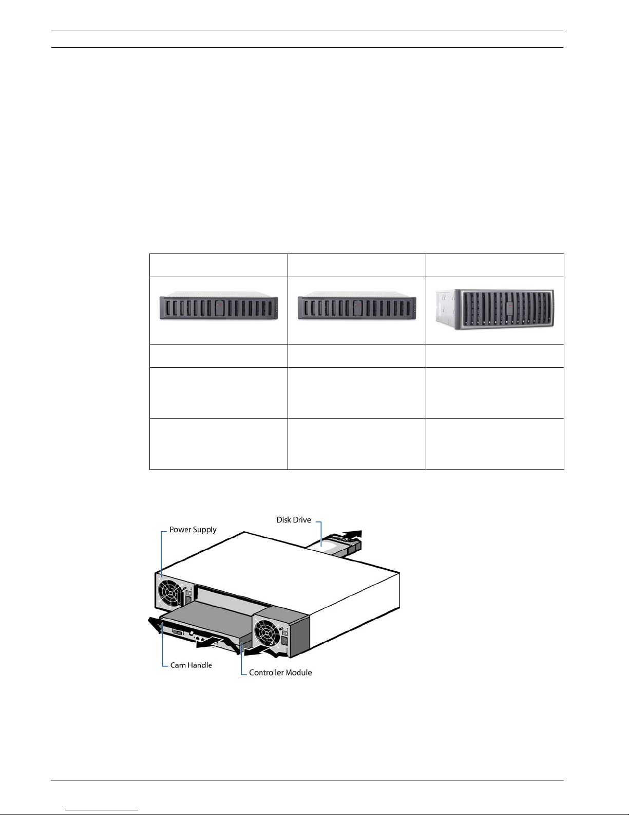
2.1 Systems at a Glance
2.1.1 Hardware Overview
Example overview (DSA-N2B20/DSA-N2B40):
DSA-N2B20 DSA-N2B40 DSA-N2B50
12/6 disks, 1 TB each 12 disks, 1 TB each 20 disks, 1 TB each
shelf expansion units
available with 14 disks
(1 TB) each
shelf expansion units
available with 14 disks
(1 TB) each
shelf expansion units
available with 14 disks
(1 TB) each
RAID-4
RAID-DP optionally
configurable
RAID-4
RAID-DP optionally
configurable
RAID-DP
DSDA Digital Storage Disk Arrays Introduction | en 7
Bosch Sicherheitssysteme GmbH Installation Guide - | V2 | 2009.11
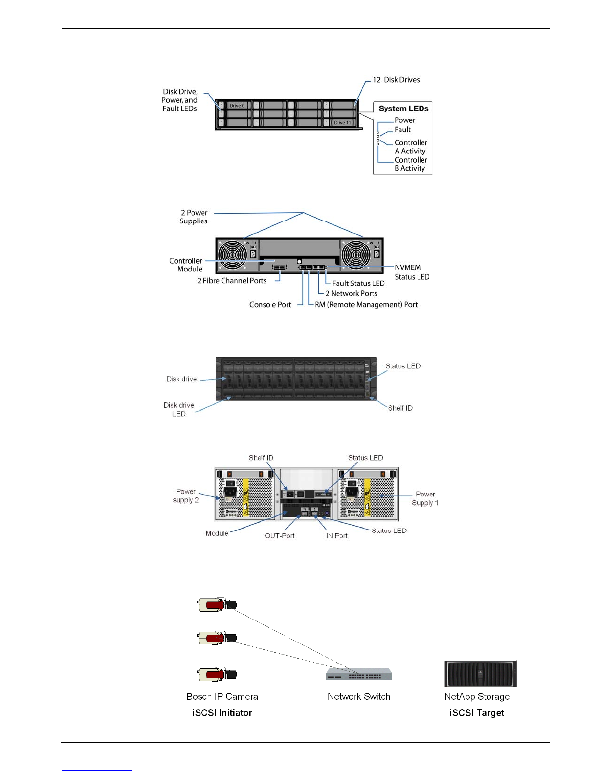
Example front side (DSA-N2B20/DSA-N2B40):
Example rear side (DSA-N2B20/DSA-N2B40):
Expansion unit – disk shelf: Front side
Expansion unit – disk shelf: Rear side
2.1.2 CCTV Integration
Example for installation without VRM:

8 en | Delivery Status DSDA Digital Storage Disk Arrays
- | V2 | 2009.11 Installation Guide Bosch Sicherheitssysteme GmbH
3 Delivery Status
For use with the VRM Video Recording Manager application or for direct recording by Bosch
cameras and senders, configure the system accordingly.
For step-by-step instructions see:
– Section 6 Configuration through the Web Interface, page 11
Preconfigured settings upon delivery:
All further configuration is done through the Web-based user interface or VRM 1.5 or higher.
Each system is delivered with the preconfigured IP address 10.10.10.10 on Ethernet port e0a
and IP address 10.10.10.11 on the second Ethernet port e0b.
DSA-N2B20 DSA-N2B40 DSA-N2B50
RAID type RAID-4 RAID-4 RAID-DP
Volume vol0 with 2 disks vol0 with 2 disks vol0 with 3 disks
IP address 10.10.10.10 10.10.10.10 10.10.10.10
IP address (2nd port) 10.10.10.11 10.10.10.11 10.10.10.11
User (Web interface) root root root
Password <blank> <blank> <blank>

DSDA Digital Storage Disk Arrays Unpacking and Installing the Hardware | en 9
Bosch Sicherheitssysteme GmbH Installation Guide - | V2 | 2009.11
4 Unpacking and Installing the Hardware
1. Unpack your system by opening the packing box and lifting the outer shipping box off the
pallet.
2. Install the appropriate rack mount for your installation and system using the Rack
Installation flyer in the rail kit box for reference.
3. Install the appropriate rack mount for any disk shelves that will be connected to the
system
4. With two people, lift the system into the rack or system cabinet, and secure it to the rack
uprights. The system weighs slightly over 30 kg (67 lb) and requires one person at the
end of the system to guide it into the rail ends.
5. For installation and wiring of additional disk shelves, see Section 7 Adding Storage,
page 20.
6. Connect the power cords, making sure that the power supplies are connected to
separate AC power sources. This ensures redundant power sources.
Make sure to set the power cable retention clips properly.
Ensure that power supply LEDs are lit.
NOTICE!
For more detailed information on the hardware installation please refer to the documentation
available on www.boschsecurity.com under Product Catalog > CCTV > Digital Recording and
Storage > Disk Arrays (Network Attached).
WARNING!
The storage system is heavy. Two people are required to lift a system.
CAUTION!
Only use the rail kit supplied with the system. Using a different rail kit can cause injury to you
or damage to your system.

10 en | Connecting the hardware DSDA Digital Storage Disk Arrays
- | V2 | 2009.11 Installation Guide Bosch Sicherheitssysteme GmbH
5 Connecting the hardware
You find descriptions on connecting the hardware in the following chapters:
– Section 4 Unpacking and Installing the Hardware, page 9
– Section 7 Adding Storage, page 20
DSDA Digital Storage Disk Arrays Configuration through the Web Interface | en 11
Bosch Sicherheitssysteme GmbH Installation Guide - | V2 | 2009.11
6 Configuration through the Web Interface
Follow these steps to configure each system. This procedure is nearly identical for all three
types of storage systems.
X Turn on the system.
DSA-N2B20 / DSA-N2B40 / DSA-N2B50 / additional disk shelves: There is a power
switch on each power supply unit (right- and left-hand side) on the rear side of the
device.
If there are additional disk shelves installed, first power on the base unit, then power on
the expansion units.
6.1 Configuration of the Network Settings and Access to the
Interface
All systems are delivered with a default IP address configuration of 10.10.10.10, subnet mask
255.0.0.0. To connect to the system, configure a network interface on your computer to use
the same network.
NOTICE!
It can take a few seconds until the LEDs on your system power supplies light up.
NOTICE!
Java Runtime Environment must be installed on your computer to use the Web interface.
Always use the most recent version.
NOTICE!
If you are using the VRM Video Recording Manager application (Version 1.5 or higher), use
VRM Configurator for the configuration steps described in Section 6.3 Configuring the Volume Section 6.5 Creating LUNs. Configure only the IP address and the date/time settings from
within the Web interface of the device (see Section 6.1 Configuration of the Network Settings
and Access to the Interface - Section 6.2 Time and Date Settings).
If you use the digital storage systems for direct recording, perform all configuration steps from
within the Web interface of the device.
12 en | Configuration through the Web Interface DSDA Digital Storage Disk Arrays
- | V2 | 2009.11 Installation Guide Bosch Sicherheitssysteme GmbH
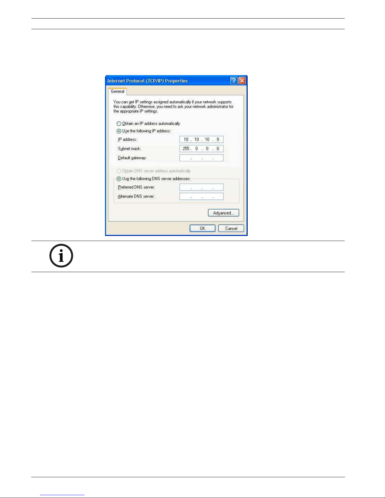
1. Select from the Control Panel of your computer Network Connections, Properties.
Here, configure your network interface to use IP address 10.10.10.9 with Subnet mask
255.0.0.0.
Example screen:
2. Connect your computer directly to the network port labeled e0a on the storage system,
using a crossover cable.
Alternatively, connect your computer to the network the storage system is connected to.
3. Open a Web browser and enter http://10.10.10.10/na_admin.
You will be asked to log in.
NOTICE!
The IP address 10.10.10.9 is an example. The IP addresses 10.10.10.10 and 10.10.10.11 are
the default IP addresses for the storage system and cannot be used otherwise.
 Loading...