

Bosch DS9432B, DS9432 Installation Instructions Manual
Installation Instructions
for the
DS9432/DS9432B Eight Input Remote Module
1.0 Description
The DS9432/B is an Eight Input Remote Module that provides a
means of addressing up to eight input loops of conventional
contacts to the multiplex bus of the DS9400 Series Fire Alarm
Control/Communicator.
2.0 Specifications
• Control Panel Requirements: The DS9432/B is designed to
work with the Detection Systems DS9400 Series Fire Alarm
Control Communicator. Version 2.0 software or higher is required
in the DS9400. The DS9400 can support up to 30 DS9432/B
modules. One DS9431 Multiplex Expansion Module is required
in the system to use the DS9432/B Eight Input Remote Module.
• Current Draw (from option bus power): 8 mA Standby and Alarm
• Current Draw (from multiplex bus loop): 10 mA Standby and
Alarm
• Total Current Draw for Battery Standby Calculation and Alarm:
18 mA Standby and Alarm
• Minimum Bus Voltage For Operation: 8 VDC peak
• Wiring: Refer to the DS9400M Reference Guide (P/N: 44578) for
the panel’s multiplex expansion module for multiplex wiring
requirements. The length of the wire connected to the loop inputs
on the DS9432/B must be less than 250 ft. (76 m) per loop.
• The recommended minimum wiring to the control is standard #18
(1.2 mm). Do not use shielded or twisted pair cable.
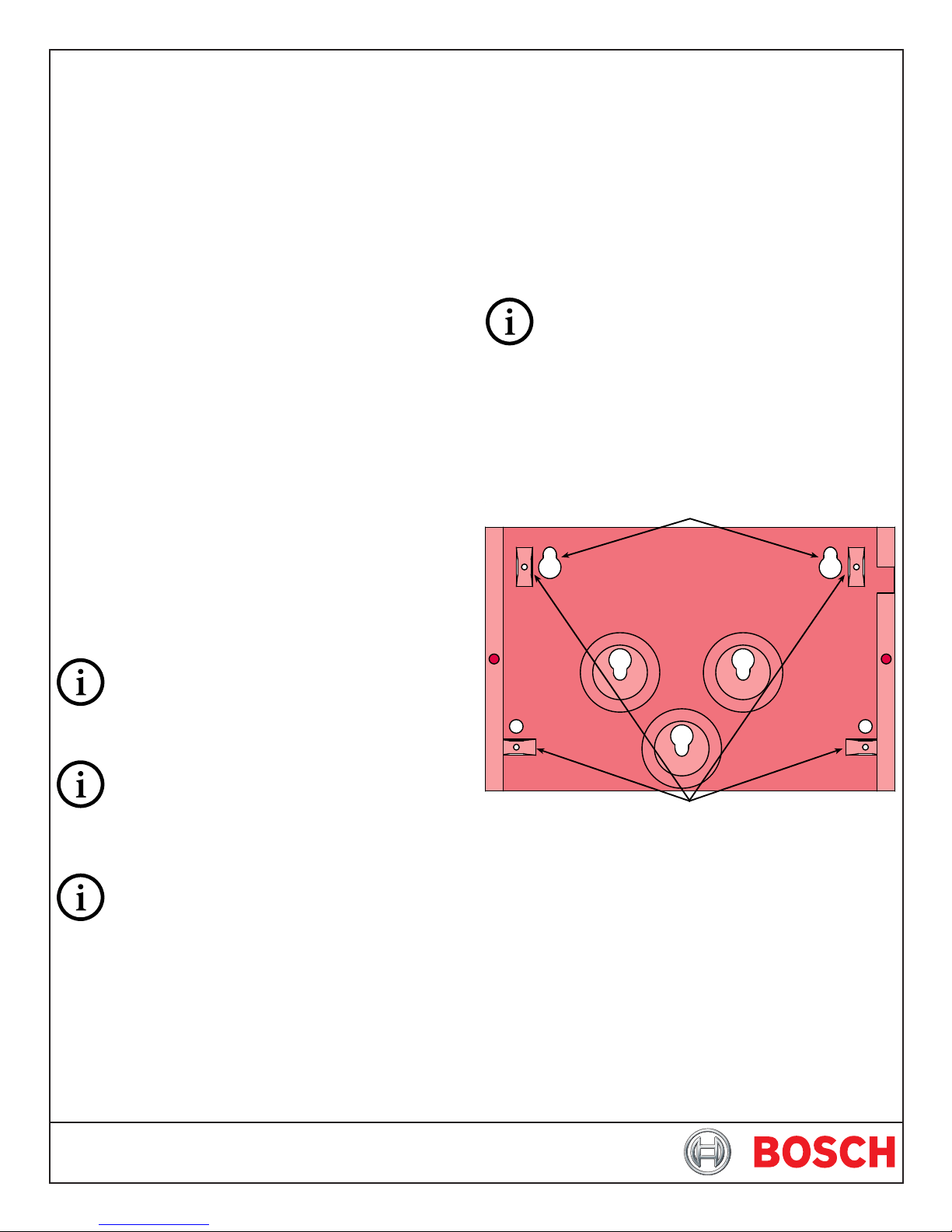
3.1 DS9432 Installation
Use the mounting holes (upper left and lower right corners) to
mount. It can be mounted inside or outside of the control enclosure.
Route wiring as necessary from the DS9431 in the control enclosure
and from the remote devices to the DS9432.
Connect wiring as shown in Figure 2.
Be sure all wiring is unpowered before routing.
If the wiring is to enter through the rear of the enclosure, open the
DS9432's rear wire entrance. If the wiring is to run along the surface
of the enclosure, open the DS9432's surface wire entrance. See Figure
2.
3.2 DS9432B Installation
The DS9432B will come partially preassembled with the circuit board
attached to the mounting skirt.
Mounting Holes
For UL Listed fire applications, minimum #18 AWG (1.2
mm) wire is required.
3.0 Installation
P3 of the DS9432 is for European applications only. Do
not put a jumper here.
P2 of the DS9432 allows the tamper switch to be bypassed with a
jumper when testing or servicing.
Remove jumper P2 when testing or servicing has been
completed.
Attach Mounting Skirt Here
Figure 1: DS9432B
Select a mounting location for the DS9432B.
Using the enclosure as a template, mark the mounting holes on the
mounting surface and make an opening for the unit’s wiring.
Next, attach the mounting skirt (with the circuit board attached) to
the enclosure (hardware provided). Then complete all wiring (see
Section 4.0).
Once installation and wiring is completed, attach the enclosure
cover and secure with the screws (provided).
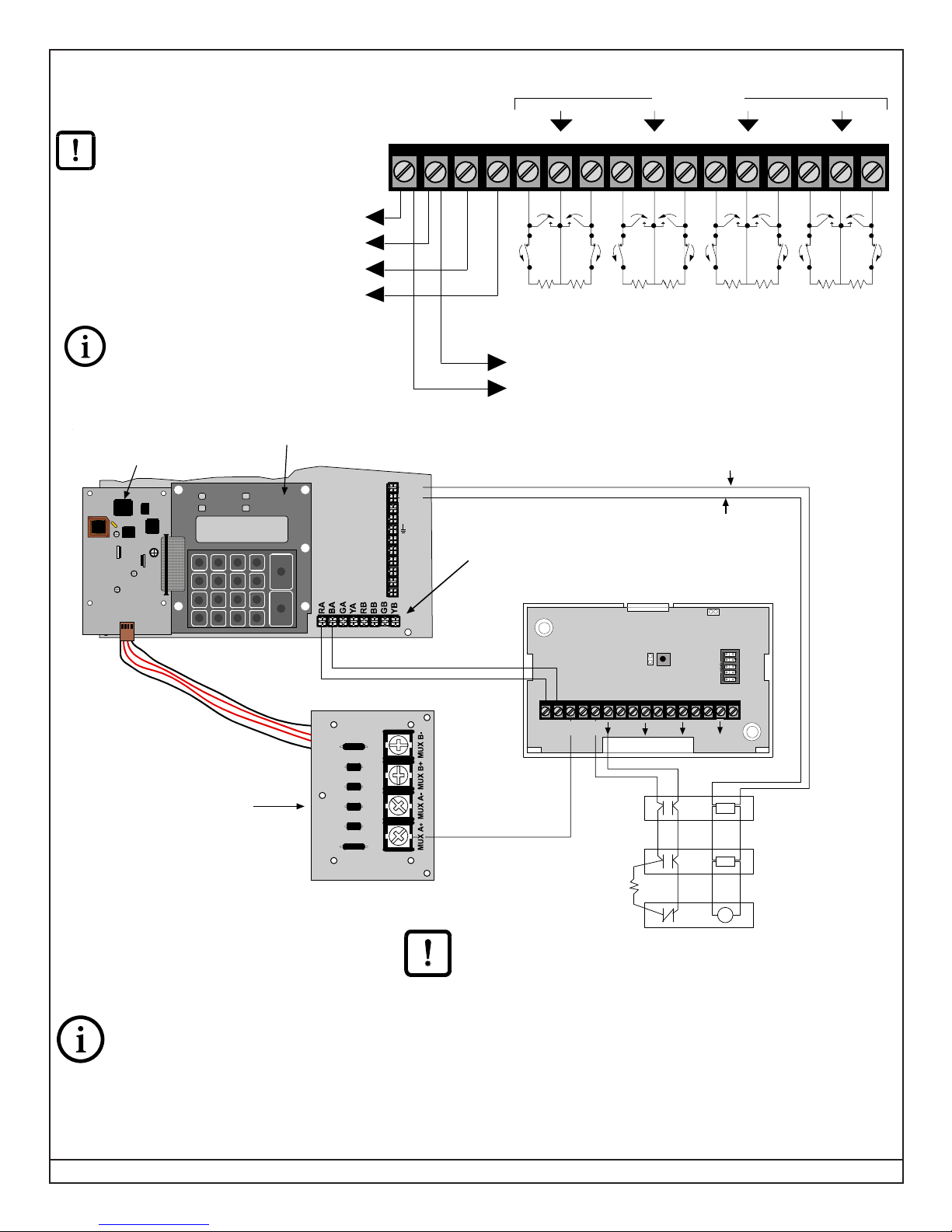
4.0 Wiring
When used with a DS9431 , power is
connected to the option bus power terminals
(RA or RB (+), BA or BB (-)). Connection to
24 VDC sources will damage the DS9432.
To control panel 12 VDC power terminals:
DS9400M, terminals RA and BA, Fig. 3
To DS9431 MUX BUS Terminals
(see Figure 3)
For UL Listed fire installations, Normally
Open (N/O) contacts must be used.
Figure 2: Wiring the DS9432/B with Separate Powered Detectors
DS9400 FACP
DS9431Multiplex Expansion Module
Troubl e
Power
Silenced
Alarm
Drill
21 3
4 5 6
7 8 9
0
Prog
Clear
*
Silence
Disable
Test
Reset
#
History
Cmnd
POWER BUS
Input Loops
+–+–12345678
NO
+
-
NO
NC
NC
+
-
EOL* EOL* EOL* EOL* EOL* EOL* EOL* EOL*
*Fire EOL resistor: 47 k ohm; DS P/N: 28010
To separate powered detectors (other than smoke detectors)
SMK+
SMKAUX+
AUX-
4L+
32L+
1-
Power + may be connected to RA or RB
on the FACP Option Bus terminal strip.
Power - may be connected to BA or BB on
the FACP Option Bus.
DS7432 Eight Input Remote Module
NO
NC
NO
NC
24V Smoke Pow er (+)
24V Smoke Power (-)
NO
NC
NO
NC
NO
NC
NO
NC
12V Power (-)
12V Power (+)
+– 23 45 67 8
+ –
1
BUS
POWER
I/O Module for the
DS9431 Multiplex
Expansion Module
Bus (+)
Bus + and Bus - are connected to
MUX A terminals for addresses 9 -
128. MUX B terminals are for
addresses 129 - 255.
NFPA 72 does not allow redundant/duplicate
ground paths, do not connect wiring to the
BUS (-) terminal on this module for fire
applications. Only the BUS (+) needs to be
connected.
Resistor
P/N: 28010
Figure 3: 4-Wire Smoke Detector Wiring for the DS9432/B and DS9400M FACP
For UL Listed fire installations, Normally Open (N/O) contacts must be used.
EOL
Smoke
Detector
Smoke
Detector
EOL
Relay
Example:
DS250 in a MB4W base
Example: EOL200
Page 2 F01U089253-01 © 2008 Bosch Security Systems, Inc. DS9432/DS9432B Installation Instructions
 Loading...